Article

Parametric Design and Mechanical Characterization of 3D-Printed PLA Composite Biomimetic Voronoi Lattices Inspired by the Stereom of Sea Urchins

by
Alexandros Efstathiadis
1,
Ioanna Symeonidou
1,
Konstantinos Tsongas
2,3,
Emmanouil K. Tzimtzimis
3 and
Dimitrios Tzetzis
3,*
1
Department of Architecture, University of Thessaly, 38221 Volos, Greece
2
Department of Industrial Engineering and Management, International Hellenic University, 57001 Thessaloniki, Greece
3
Digital Manufacturing and Materials Characterization Laboratory, School of Science and Technology, International Hellenic University, 57001 Thermi, Greece
*
Author to whom correspondence should be addressed.
J. Compos. Sci. 2023, 7(1), 3; https://doi.org/10.3390/jcs7010003
Submission received: 13 October 2022 / Revised: 15 November 2022 / Accepted: 12 December 2022 / Published: 26 December 2022
(This article belongs to the Special Issue 3D Printing Composites)

Abstract

:
The present work is focused on the analysis of the microstructure of the exoskeleton of the sea urchin Paracentrotus lividus and the extraction of design concepts by implementing geometrically described 3D Voronoi diagrams. Scanning electron microscopy (SEM) analysis of dried sea urchin shells revealed a foam-like microstructure, also known as the stereom. Subsequently, parametric, digital models were created with the aid of the computer-aided design (CAD) software Rhinoceros 3D (v. Rhino 7, 7.1.20343.09491) combined with the visual programming environment Grasshopper. Variables such as node count, rod thickness and mesh smoothness of the biologically-inspired Voronoi lattice were adapted for 3D printing cubic specimens using the fused filament fabrication (FFF) method. The filaments used in the process were a commercial polylactic acid (PLA), a compound of polylactic acid/polyhydroxyalkanoate (PLA/PHA) and a wood fiber polylactic acid/polyhydroxyalkanoate (PLA/PHA) composite. Nanoindentation tests coupled with finite element analysis (FEA) produced the stress–strain response of the materials under study and were used to simulate the Voronoi geometries under a compression loading regime in order to study their deformation and stress distribution in relation to experimental compression testing. The PLA blend with polyhydroxyalkanoate seems to have a minor effect on the mechanical behavior of such structures, whereas when wood fibers are added to the compound, a major decrease in strength occurs. The computational model results significantly coincide with the experimental results.

1. Introduction

Nature has developed an abundance of high-performance structures and materials through billions of years of evolution. Biomimicry is considered a new science that studies nature’s concepts and principles and then draws inspiration from these designs and processes to solve human problems [1]. Nowadays, a major paradigm shift is taking place in design and material science where biological systems are being used as valuable sources of inspiration in the fields of advanced material technology and architectural, mechanical, hydrodynamic, optical and electrical design in an attempt to discover solutions to contemporary design challenges [2,3]. However, the application of these principles in the design process is challenging as architects, engineers and other scientists have struggled with processing all the available biological information. The existing knowledge gap and new terminology hamper the effort of comprehending and analyzing the mechanisms and concepts that are found in nature and could provide useful design solutions [4]. To tackle this problem, specialized methodological tools have been created, such as AskNature [5] and the biomimetic design spiral [6], in an attempt to support and streamline the biomimetic design process. Exoskeletons are a type of biological structure that has been previously studied for potential biomimetic applications [7,8,9,10,11]. They can be found in diverse organisms such as seashells and insects and they perform numerous functions such as mechanical protection from predatory attacks, including penetration, fatigue, drilling, crushing, etc. [12]. As a result, they have developed exceptional mechanical properties such as toughness, damage tolerance and impact resistance that prevent catastrophic failure of the structure [13].
Parametric design allows for the creation of complex, biomimetic geometries, and the exploration of a wider range of design possibilities [14]. Parametric design is an algorithmic design process that is comprised of a direct acyclic graph (DAG) where the nodes of the graph are schemes that contain variables and constraints [15]. The nodes can be distinguished into dependent and independent ones. The dependent components are informed unidirectionally by variables found earlier in the graph, while the independent nodes determine the descendant variables and are usually parameters that can be customized by the end user on demand, to derive an infinite number of design permutations [16]. Parametric design is driving a paradigm shift in design thinking as it enables designers to rapidly create, evaluate and reconfigure, with the use of algorithmic methods, a large number of topologies that would otherwise be extremely laborious to design [17]. Furthermore, such complex structures surpass the technical capabilities of traditional fabrication technologies that have obstructed advancements in biomimetic research and the application of biological design solutions in contemporary design challenges [18,19,20]. However, advancements in additive manufacturing (AM) or other 3D printing technologies such as fused filament fabrication (FFF), stereolithography (SLA), selective layer sintering (SLS) and others, have created new opportunities and enabled the construction of intricate structures and advanced materials that could not have otherwise been achieved [21,22,23,24,25].
More specifically, fused filament fabrication (FFF) is a 3D printing technology where successive cross-sectional layers of the model are built as the melted filament is extruded through the printer’s nozzle and deposited layer upon layer until the desired structure is fabricated [26]. The comparative advantages of FFF technology are a wide range of filament materials [27] that are eco-friendly [28] in a cost and time-effective process [29] that produces structures of excellent mechanical performance [30]. However, limitations also exist that are inherent in the fabrication technology [31]. As the melted filament is deposited on top of an existing surface, overhanging parts require support structures to be successfully printed, which are subsequently removed, resulting in an increased design and build time as well as energy and material waste [32]. The use of 3D-printed polymers for final product fabrication is rare nowadays due to their poor mechanical behavior, as well as due to poor electrical and thermal properties [33,34]. Therefore, reinforced polymers could be potentially used to overcome those disadvantages [35,36]. To overcome such an issue, the addition of chain extenders and inclusions has been investigated [37,38] during the preparation of the filament, with success leading to improvements in melt strength by promoting polymeric chain entanglement and limited degradation.
A novel systematic strategy of biomimetic design is expected as an outcome of the present study that merges the practice of biomimicry with algorithmic design, additive manufacturing, and digital tools of analysis and optimization. Initially, it aims to examine the structure of the exoskeleton of the sea urchin (also known as the test) and to extract design concepts that could find application in the architectural and engineering fields. These concepts were subsequently modeled with the help of 3D computer-aided design (CAD) software and parametric algorithmic modeling (Rhinoceros 3D, Grasshopper 3D, etc.) in order to develop an interactive design algorithm that can be customized by the designer in real time. The FFF additive manufacturing technology was selected to assess the manufacturability of biologically inspired Voronoi lattice structures. The mechanical response of commercial filaments of polylactic acid (PLA), a compound of polylactic acid/polyhydroxyalkanoate (PLA/PHA) and a wood fiber polylactic acid/polyhydroxyalkanoate (PLA/PHA) composite were evaluated using nanoindentation tests coupled with a finite element model to derive the stress–strain curves. In addition, mechanical tests of the biomimetic Voronoi cubic were conducted in compression and simulated through finite element analysis (FEA).

2. Materials and Methods

2.1. Design and Fabrication

The biomimetic design spiral has functioned as a guideline for the present biomimetic study. A structure with significant mechanical properties was identified in the exoskeleton of the sea urchin [39,40]. Sea urchin tests of the species Paracentrotus lividus, as determined according to the Greek Fisheries Control Agency [41], were gathered at the Thermaikos bay area, Greece. P. lividus is commonly found around the Mediterranean Sea and the northeastern Atlantic Ocean [42]. Microscopy analysis was performed using a digital microscope Dino-Lite Pro HR—AD7013MZT (Dino-Lite Europe, Almere, The Netherlands) to analyze the mesoscopic structure of the echinoid’s test. Furthermore, samples were prepared for scanning electron microscopy (SEM) using the Phenom ProX Desktop SEM (Thermo Fisher Scientific, Waltham, MA, USA) in order to study the microstructure of the samples. The Quorum SC7620 Sputter Coater (Quorum Technologies, Laughton, UK) was utilized to coat the samples with gold (Au) particles to inhibit charging and reduce thermal damage, and they were mounted on the SEM platform with double-sided carbon tape.
The microscopic analysis served as the basis for the design phase of the biomimetic process. The computer-aided design (CAD) software Rhinoceros 3D (Robert McNeel & Associates, Seattle, WA, USA) in conjunction with the embedded visual programming environment Grasshopper 3D (Robert McNeel & Associates, Seattle, WA, USA) was used for the creation of an interactive design algorithm [43]. Additional Grasshopper plug-ins were required, such as Dendro (ECR Labs, Los Angeles, CA, USA), a volumetric modeling tool based on the OpenVDB library, which creates volume data structures that are easier to process than traditional meshes or boundary representations (BREP) and allows for faster computational times and more complex operations [44], as well as Topologizer (David Stasiuk and Daniel Piker), a tool used to clean up wireframes or line networks [45].
The biomimetic model was adapted for 3D printing on the BCN Sigma R17 printer (BCN3D Technologies, Barcelona, Spain). Three commercial composite filaments were used in this study, and Figure 1 shows the cross-sections of these three filaments using a scanning electron microscope. Neat polylactic acid was used as the control material, being the most widely used FFF material, while a compound of polylactic acid/polyhydroxyalkanoate (PLA/PHA) and a PLA/PHA/wood fiber composite (colorFabb B.V., Belfeld, The Netherlands) were assessed for comparison, and as a proof of concept for sustainable materials.
The slicing process was carried out on the Ultimaker Cura slicer (v.4.9.1, Ultimaker, Utrecht, The Netherlands). No additional support structures were utilized, as the design, printing and removal process of such supports in intricate, biomimetic structures would be overcomplicated and time-, energy- and material-consuming [32].

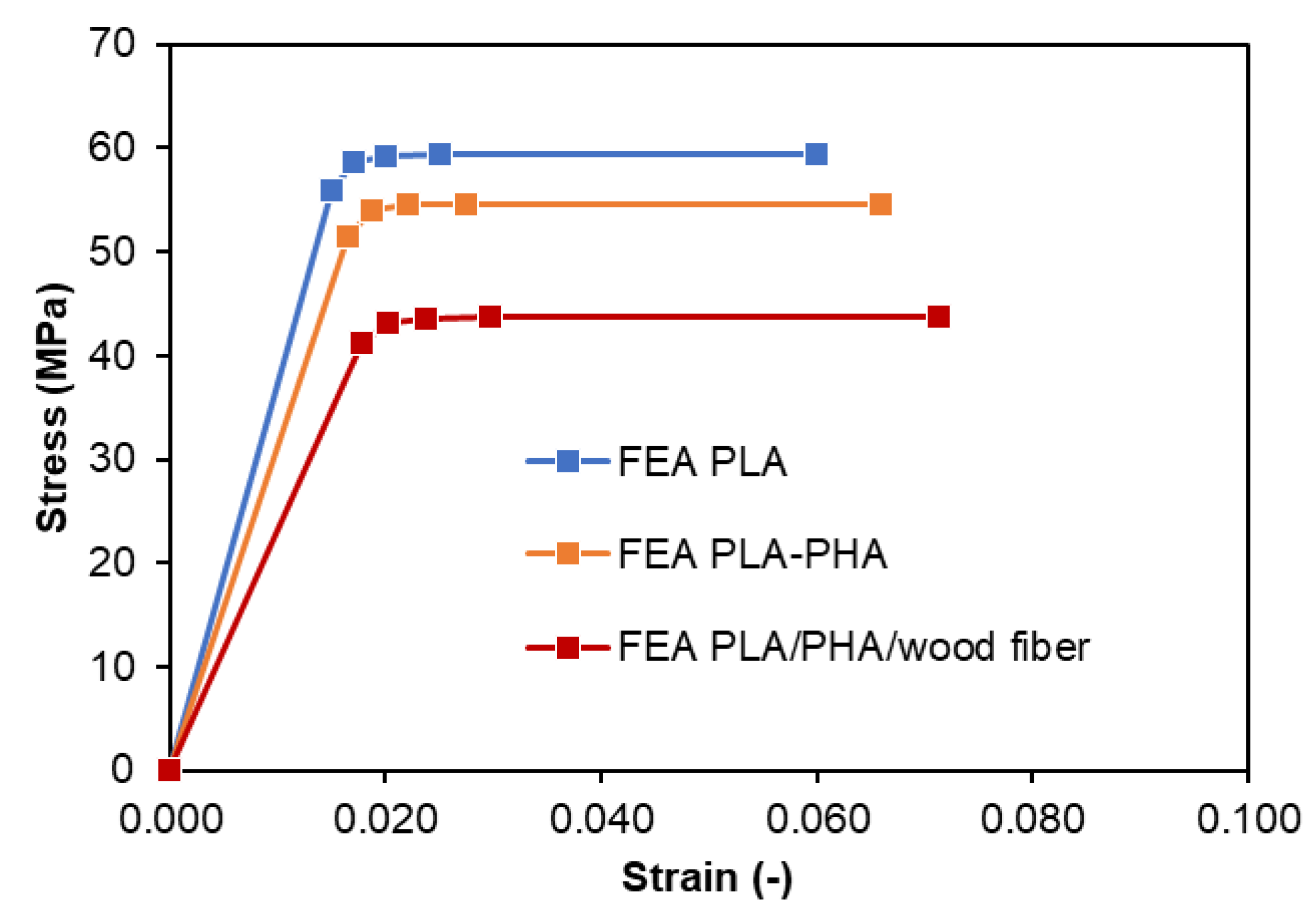
2.2. Compression Testing Supported by FEA

The Voronoi lattice structures were examined under uniaxial quasi-static compression at room temperature with three repetitions for each design in order to extract reliable results with the minimum standard deviation. For this process, a universal testing machine (M500-50AT Testometric Company, Rochdale, UK) was utilized, equipped with a 50-kN load cell. It is worth mentioning that all experiments were performed with a strain rate of 5 mm/min. The mechanical behavior of all the Voronoi lattice structures was investigated with the ANSYS™ software (ANSYS, Inc., Canonsburg, PA, USA). An explicit dynamic analysis was performed to accurately simulate the mechanical response of the lattices in order to capture their large deformations and bi-linear material behavior. To ensure a mesh-independent response, a convergence study was performed. This study showed that convergence on stress was achieved with almost 130,000 elements for each verification model.

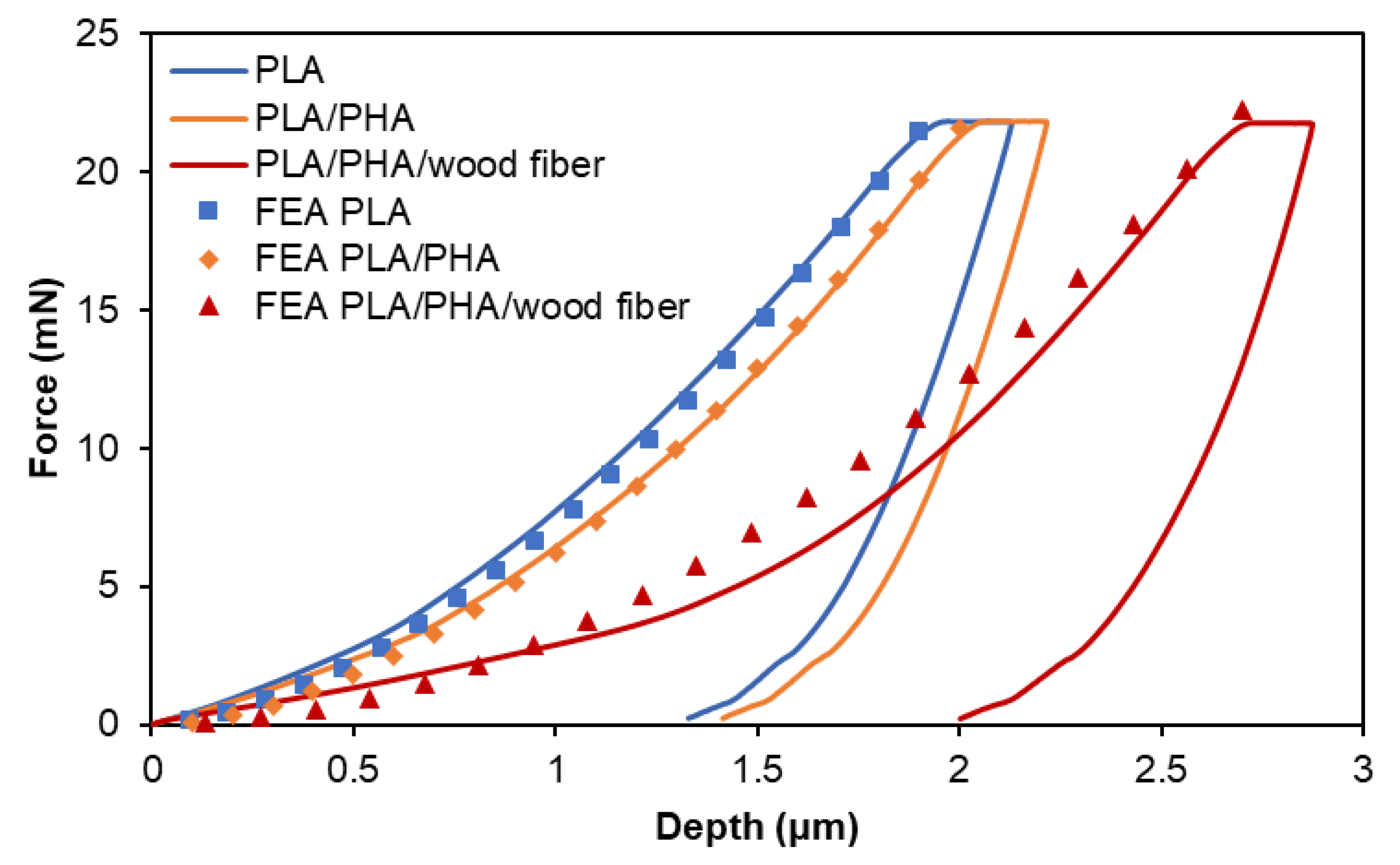
2.3. Nanoindentation Testing Supported by FEA

The nanomechanical properties of the PLA, PLA/PHA and PLA/PHA/wood fiber composite filaments were investigated using nanoindentation. A dynamic ultra-microhardness tester DUH-211S (Shimadzu Co., Kyoto, Japan) utilizing a 100 nm radius triangular pyramid indenter tip (Berkovich-type indenter with 115 tip angle) was used to determine the mechanical performance of the specimens. During nanoindentation testing, a controlled load with a peak load of 20 mN was applied through a diamond tip on the surface of the nanocomposite filaments and was held for 3 s. As a function of load, the indentation depth was recorded. The indenter was then unloaded, resulting in a load of zero. During the creep time, the maximum indentation load is applied to the indenter. The average value of ten measurements was used to calculate the modulus and hardness [46,47]. A finite element analysis (FEA) process was developed to fit the nanoindentation test curves and extract the stress–strain behavior of the PLA composite specimens. The interface between the indenter and the surface of the PLA composites was simulated with contact elements and assumed to be frictionless. The nanoindentation experiments were computationally generated considering the simulation of the loading stage of the indenter penetrating into the surface of PLA specimens. Other works [48,49,50] have shown that kinematic hardening leads to a rapid convergence in the corresponding FEA calculations, so this method was utilized in the developed curve-fitting procedure.

3. Biomimetic Design Process

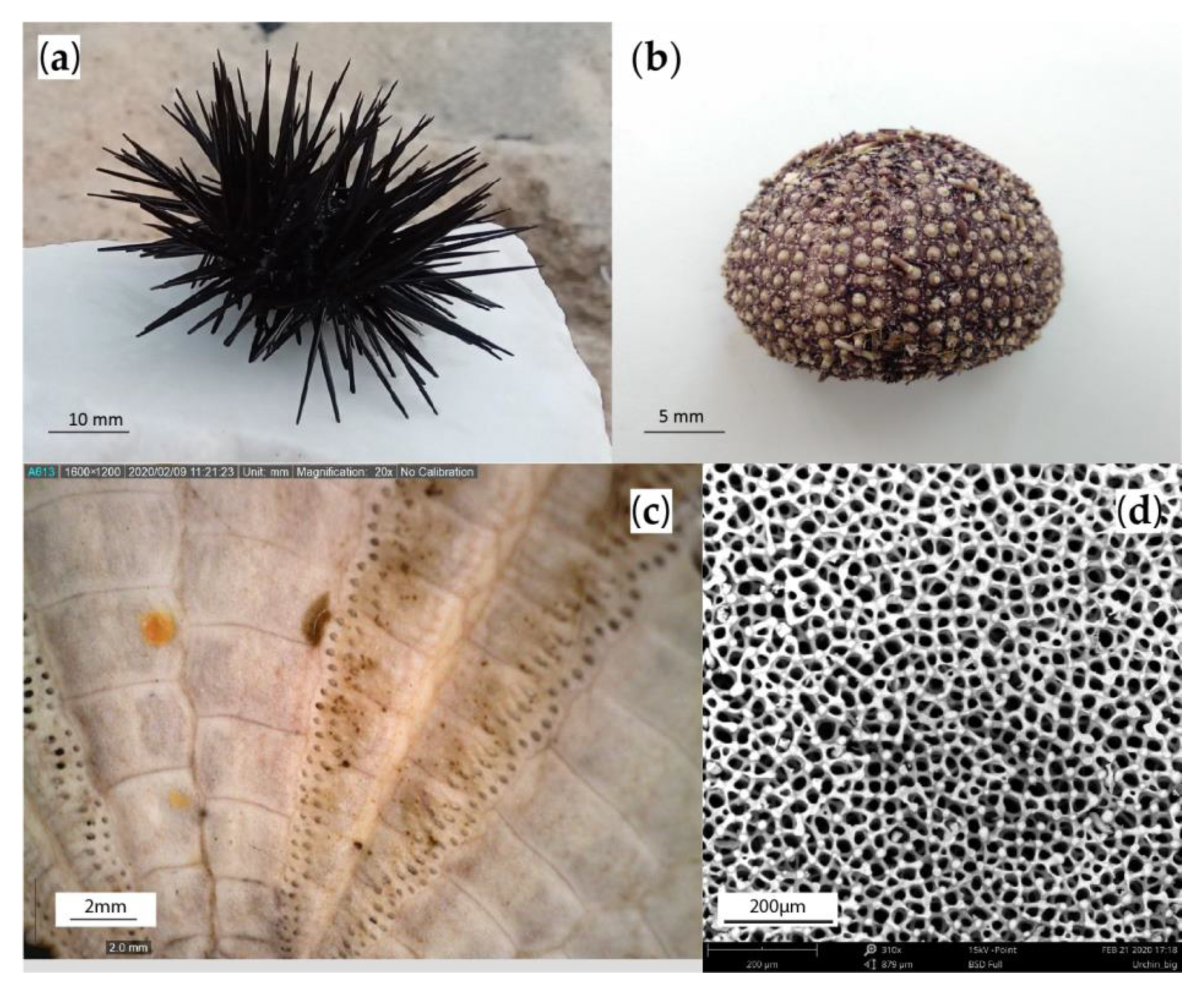
3.1. Morphological Analysis of the Biological Sample

The typical diameter of the test of Paracentrotus lividus ranges between 30 and 45 mm, as seen in Figure 2a,b and also reported elsewhere [51]. At a macroscopic level, the urchin’s test is characterized by its domed shape (Figure 2b) with a fivefold symmetry, similar to other echinoids, such as starfish [52]. Moreover, pronounced ribs can be identified along the plate edges of radial sutures (Figure 2c) which enhance the structural integrity of the skeleton [53]. The sea urchin is a hierarchical biological structure that is composed of multiple high-magnesium calcite hexagonal plates sewn together by ligaments made of collagen fibers that wrap around trabeculae (calcite rods) that protrude from their edges and interlock adjacent plates [54]. The collagenous ligaments also increase the stiffness of the test through uniform distribution of stresses, with radial sutures being thicker than circumferential ones [55]. Ellers et al. [56] have demonstrated that fresh, intact sea urchin tests, when under crushing load, failed at much higher forces compared to tests that had their ligaments removed. SEM analysis of the test’s microstructure reveals a complex, three-dimensional porous structure, as illustrated in Figure 2d, that resembles a foam and is known as the stereom [57].

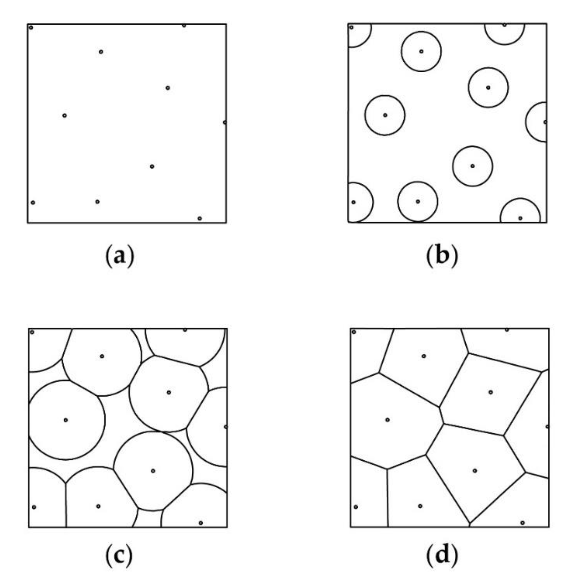
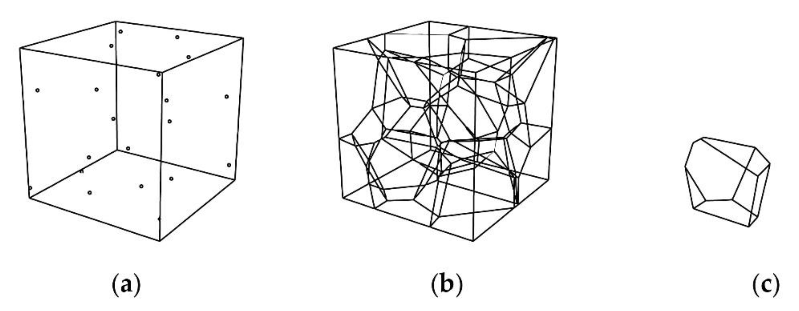
3.2. 3D Voronoi Geometry

The microscopic structure of the stereom of the echinoid can be geometrically described by a 3D Voronoi diagram. Voronoi diagrams, originally characterized by Dirichlet (1850) and Voronoi (1908), can be found in many natural models and are considered as some of the most important topologies defined by a set of points [58]. According to Fantini et al. [59], an ordinary (2D) Voronoi diagram can be described if initially a specific 2-dimensional Cartesian space contains a finite number (n) of points (with n > 1), called seeds. A circle with a 0 starting radius is drawn around each seed, expanding at the same rate until two circles come into contact so that a linear boundary is formed. The expansion of the circles continues until no further expansion is possible within the finite space, and convex polygon cells are formed, as illustrated in Figure 3. The outcome is an ordinary Voronoi diagram for that specific point set. The mathematical expression of such a Voronoi diagram is [60]:
V(pi) = {p|d(p, pi) ≤ d(p, pj), j ≠ i, j = 1, …, n},
where:
  • p1,…, pn is a set of distinct seeds located in Cartesian space Rd;
  • d(p, pi) represents the Euclidean distance between location p and seed pi;
  • V(pi) represents the ordinary Voronoi diagram associated with seed pi.
Voronoi diagrams can also be drawn in higher dimensions, as shown in Figure 4. In 3D space, spheres are drawn instead of circles and the boundaries are faces instead of edges. The resulting cells are convex polyhedrons instead of convex polygons [60]. This kind of 3D Voronoi diagram is employed in the present work for the generation of three-dimensional digital models, inspired by the urchin’s stereom.

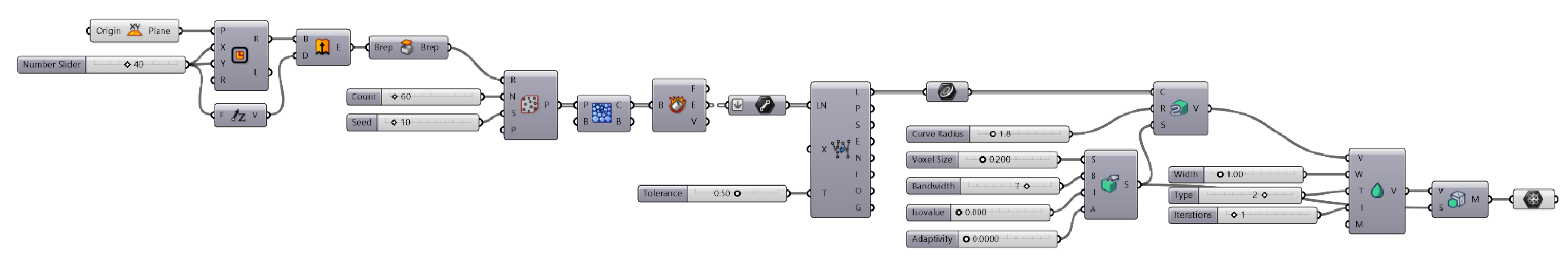
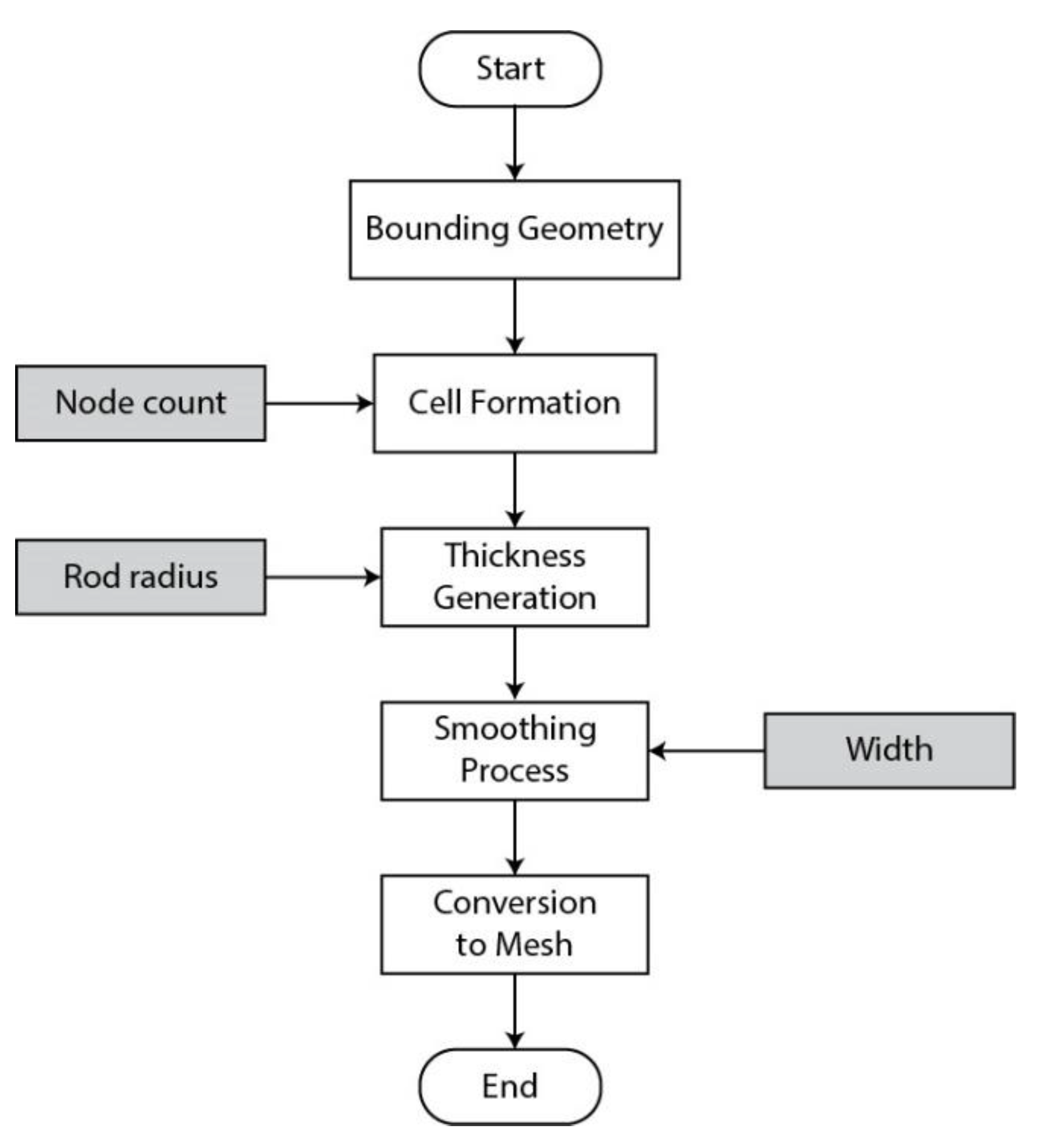
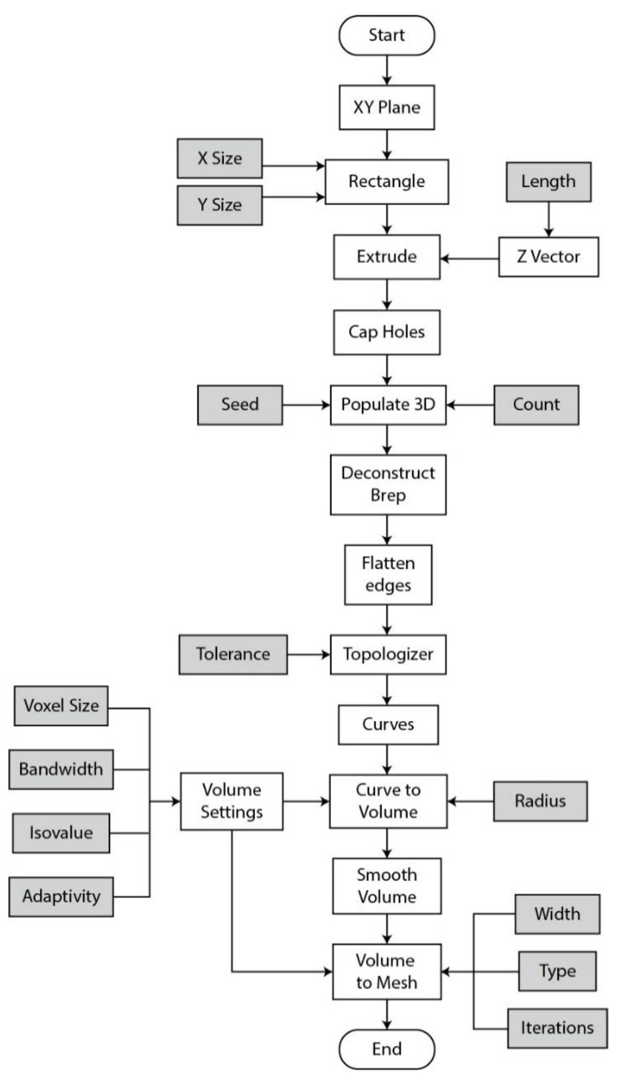
3.3. Algorithmic Design

An algorithmic design process has been developed in order to transfer the design concepts identified in the sea urchin’s stereom into a 3D digital model. The CAD software Rhino 3D was used in tandem with the visual programming language Grasshopper 3D. At the top algorithmic level, a bounding geometry is initially created. Afterward, the cells of the Voronoi lattice are formed with a user-defined number of nodes. Next, a custom thickness is applied to the lattice to create a Dendro volume. A parametrized smoothing operation is subsequently applied to the volume which, in the end, is converted into a mesh. The complete definition, as scripted on the Grasshopper canvas, can be found in Figure 5, while the top-level workflow diagram of the algorithmic design process is explained in Figure 6.
At the second level of the algorithm, which is illustrated in Figure 7, the bounding geometry is created by drawing a rectangle on the XY plane with customizable X and Y dimensions. The rectangle is then extruded along the Z direction at a custom length and the holes of the BREP are capped as shown in Figure 7. Afterward, the geometry is populated (“Populate 3D” command) with a user-specified number of randomly distributed points. Next, the “Voronoi 3D” component is applied to draw polyhedral cells around each point and within the bounding geometry. The cells are deconstructed into their faces, edges and vertices. The output edges constitute the rods of the biomimetic 3D Voronoi lattice. The edges are extracted and cleaned from any overlapping or duplicate lines with the aid of the plug-in Topologizer with user-defined tolerance.
The lines are converted to curves, which are, then, turned into solid beams with the implementation of the Dendro Grasshopper plug-in. The “Curve to Volume” command wraps the curves with a spherical profile of a user-defined radius and creates a single volume. A set of volume settings must also be applied. First, a voxel size must be set which determines the size of the individual voxels that make up the volume. Bandwidth controls the active voxel field around the volume. Isovalue affects the accuracy of the mesh to the original value which can loosely be described as a type of offset. Small changes to isovalue usually resolve “invalid mesh” errors. Lastly, adaptivity controls the variability of mesh faces. High values of voxel size and adaptivity along with low values of bandwidth minimize the required calculations and make processing of the volume easier while working. Once the desired result is achieved, these values can be lowered and raised, respectively, to create a more precise, high-resolution model.
The “Smooth Volume” component runs a parameterized smoothing operation on the volume. The first parameter that must be set is the type of smoothing. Four types are available: Gaussian, Laplacian, mean and median. The mean smoothing type was used in the case of the Voronoi lattice. Width controls the scale of the smoothing process, while iterations determines how many times the smoothing process is performed. Finally, the Dendro volume is converted into a Grasshopper native format with the “Volume to mesh” component that outputs a mesh geometry of the Voronoi lattice. The same set of volume settings, used earlier to create the original Dendro volume, is applied here as well.

4. Results and Discussion

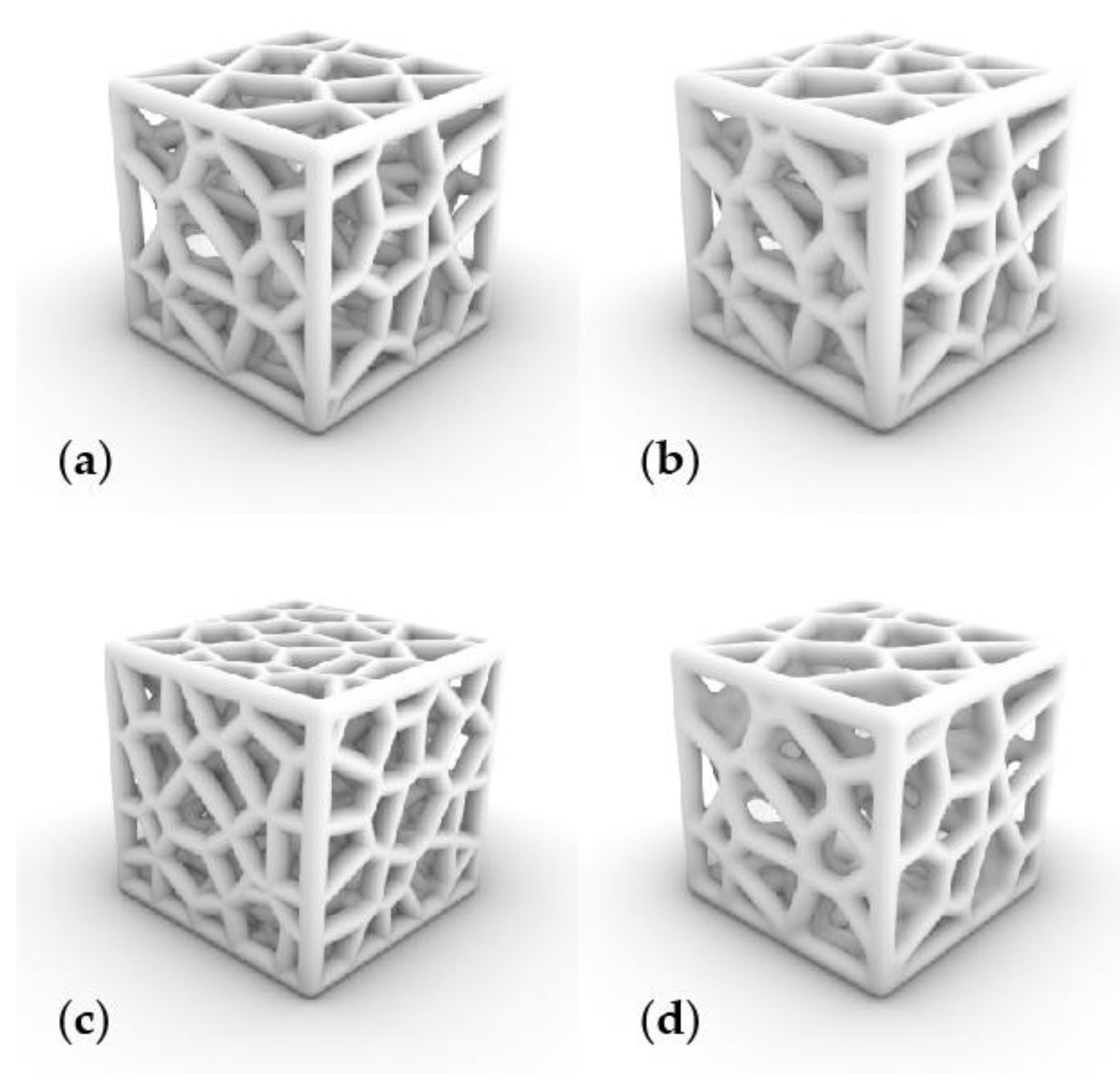
4.1. Algorithmic Design Results

The described Grasshopper definition enables the generation of an interactive Voronoi model with multiple user-defined parameters. The most important of these are the number of nodes (Count), the thickness of the trabeculae (Curve radius) and the overall smoothness of the geometry (Width). Figure 8 shows four indicative variations of the Voronoi lattice model based on changes in these three parameters.
Model A has XYZ dimensions of 40 × 40 × 40 mm3, a node count of 60, a curve radius of 1.8 mm and a smoothness width scale of 1. In Model B, the curve radius was changed to 2.4 mm while all the rest of the parameters remained the same. Model C has a node count of 120 with a curve radius of 1.8 mm and unchanged smoothness width. Lastly, the node count of Model D is 60, the curve radius 1.8 mm while the smoothness width scale is altered to 6. Overall XYZ dimensions are the same in all models. The different sets of parameter values of the four models are shown on Table 1. The result is a highly customizable and versatile Voronoi structure that can be effectively applied to any bounding geometry and imitate biological design paradigms. An advantage of such a design approach is that the digital model can be customized on-demand by the user through a series of interactive parameters that modify the end geometry and generate unlimited design iterations. Another advantage of the tools that were used in the design process is that, despite the apparent complexity of the model’s geometry and definition, limited computational power is required. This allows for a rapid and effortless design, evaluation and optimization process.

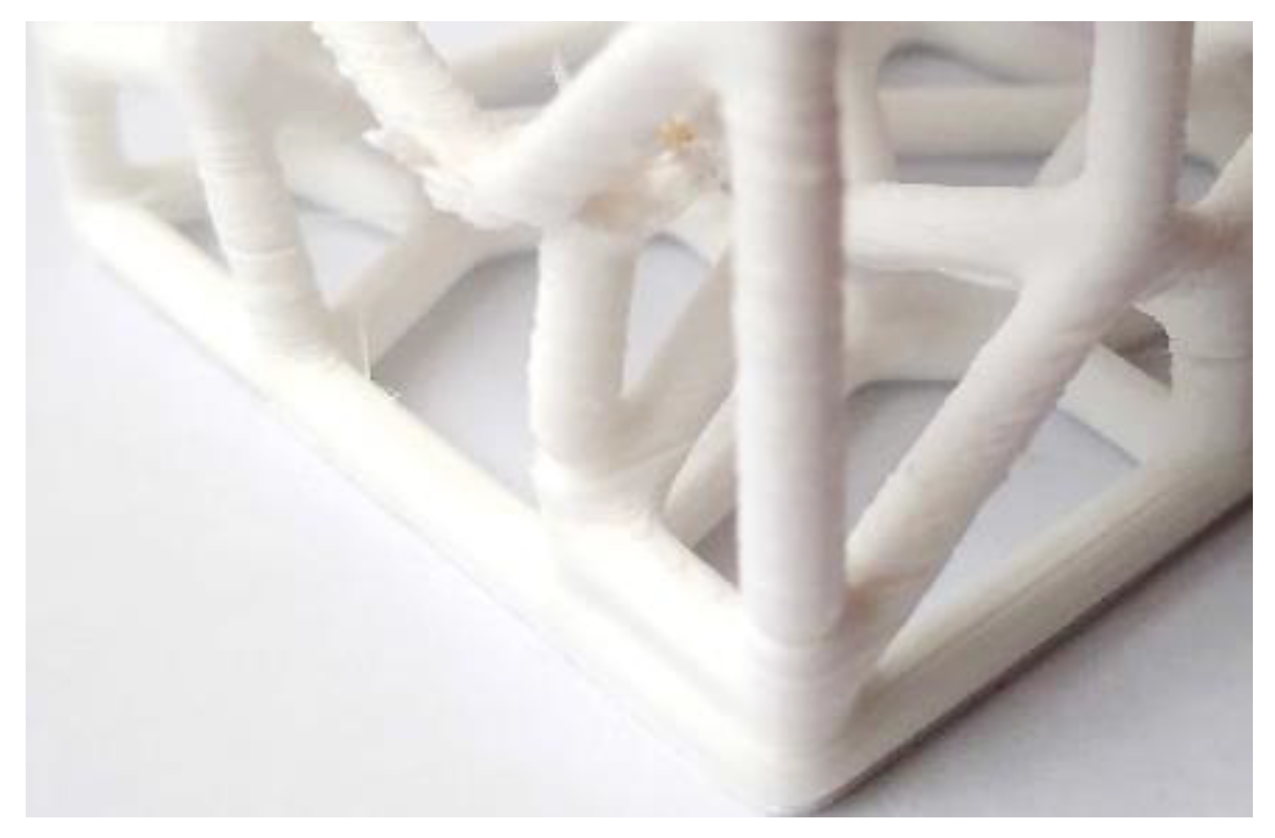
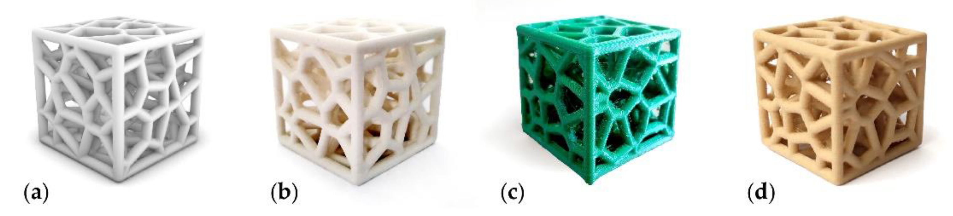
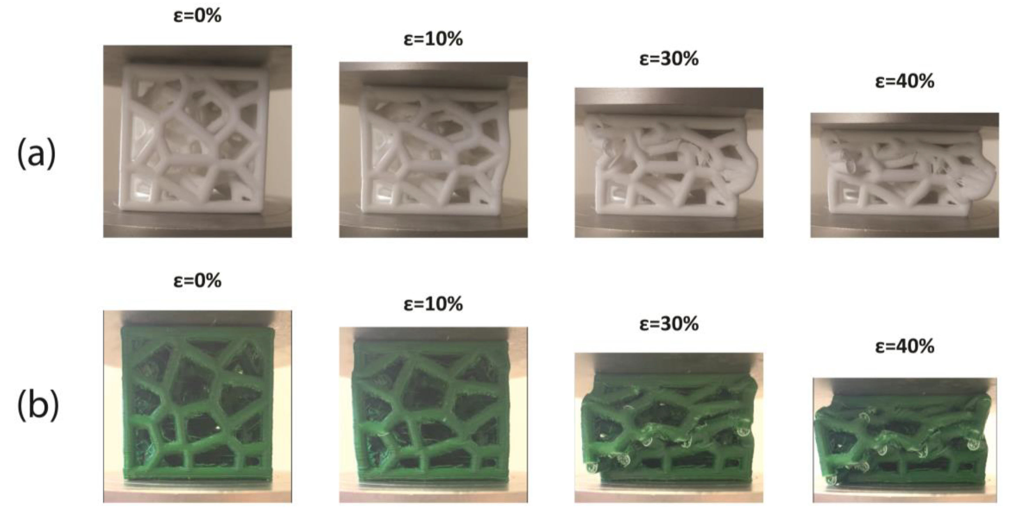
4.2. FFF Printing Results

Several versions of the Voronoi model were 3D printed using an FFF method without additional support to acquire, through trial and error, a printed sample with no apparent structural defects. Throughout these attempts, it became obvious that the main design parameters that determine the success of the printing process were the radius of the rods and the number of nodes which in turn determine the length of the rods (fewer nodes result in longer rods). Longer and thinner rods were more susceptible to manufacturing defects and poor bonding, as shown in Figure 9. The baseline for a successfully printed Voronoi lattice model was determined to be a node count of 60, rod (curve) radius of 1.8 mm and smoothness width of 1 for a cubic bounding box with XYZ dimensions of 40 × 40 × 40 mm3. The complete set of design parameter values can be found in Table 2.
As for the printer parameters, the outer wall printing speed was determined to have a significant impact on the printing quality of the structure. As a result, a slow outer wall speed of 15 mm/s was selected. Inner wall and infill speed did not appear to impact the build quality and a higher speed of 30 mm/s was selected for both. Another important printing parameter is layer thickness. Lower layer thickness results in a better 3D printing outcome. However, thinner layers can significantly raise the printing time. Thus, a compromise between quality and reasonable printing time had to be made with a layer thickness of 0.2 mm. Furthermore, a 0.4-diameter nozzle was used while a 100% infill density was selected with a line pattern. The nozzle printing temperature was set at 205 °C while the build plate temperature was fixed at 55 °C. No additional structural supports were utilized. The complete printing parameters can be found in Table 3.
To verify the reproducibility of the biomimetic structure, two additional commercial composite filaments were used. The first one is a compound of polylactic acid/polyhydroxyalkanoate (PLA/PHA), while the second one is a composite of PLA/PHA mixed with wood fibers. The same slicing and printing parameters were applied for these prints as before. Successful samples were manufactured proving that the reported strategy of designing and manufacturing a sea urchin-inspired, biomimetic Voronoi structure can be replicated across different materials. Figure 10 shows a comparison between the digital and the printed models.
Minor defects were identified, with the aid of optical microscopy, on overhang parts for all types of materials which can be regarded as an inherent limitation of the FFF technology. Nevertheless, such flaws were rare, observable once or twice on each face of the samples and limited in length, without compromising the overall structural integrity of the printed lattices.

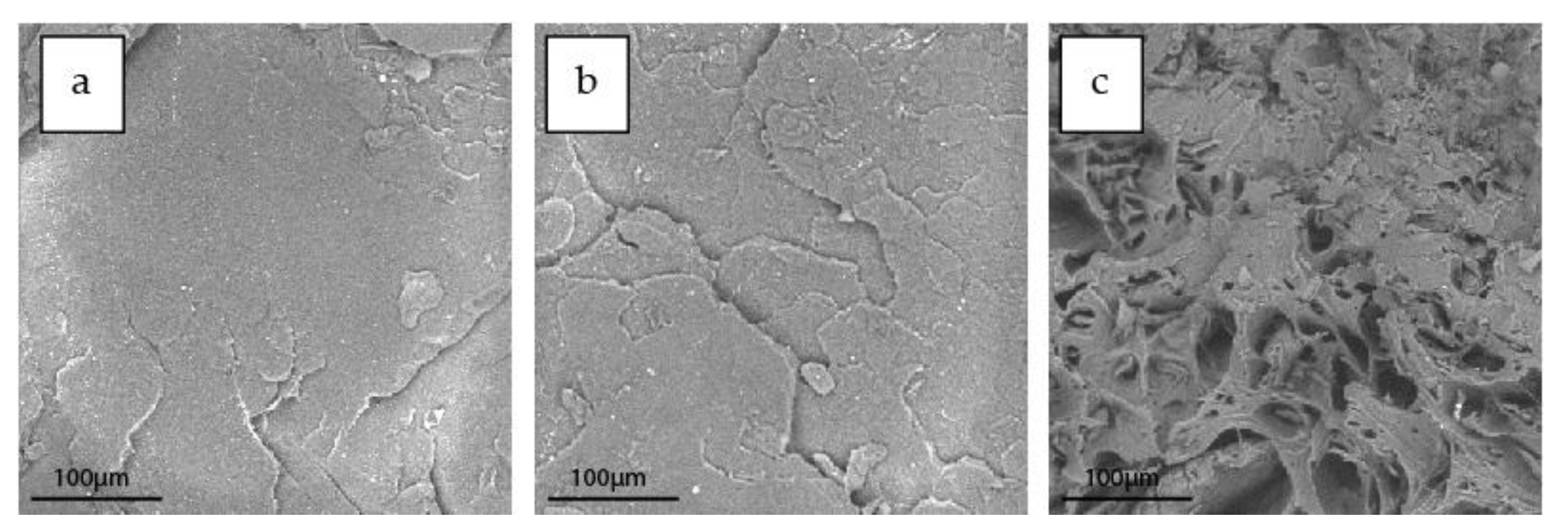
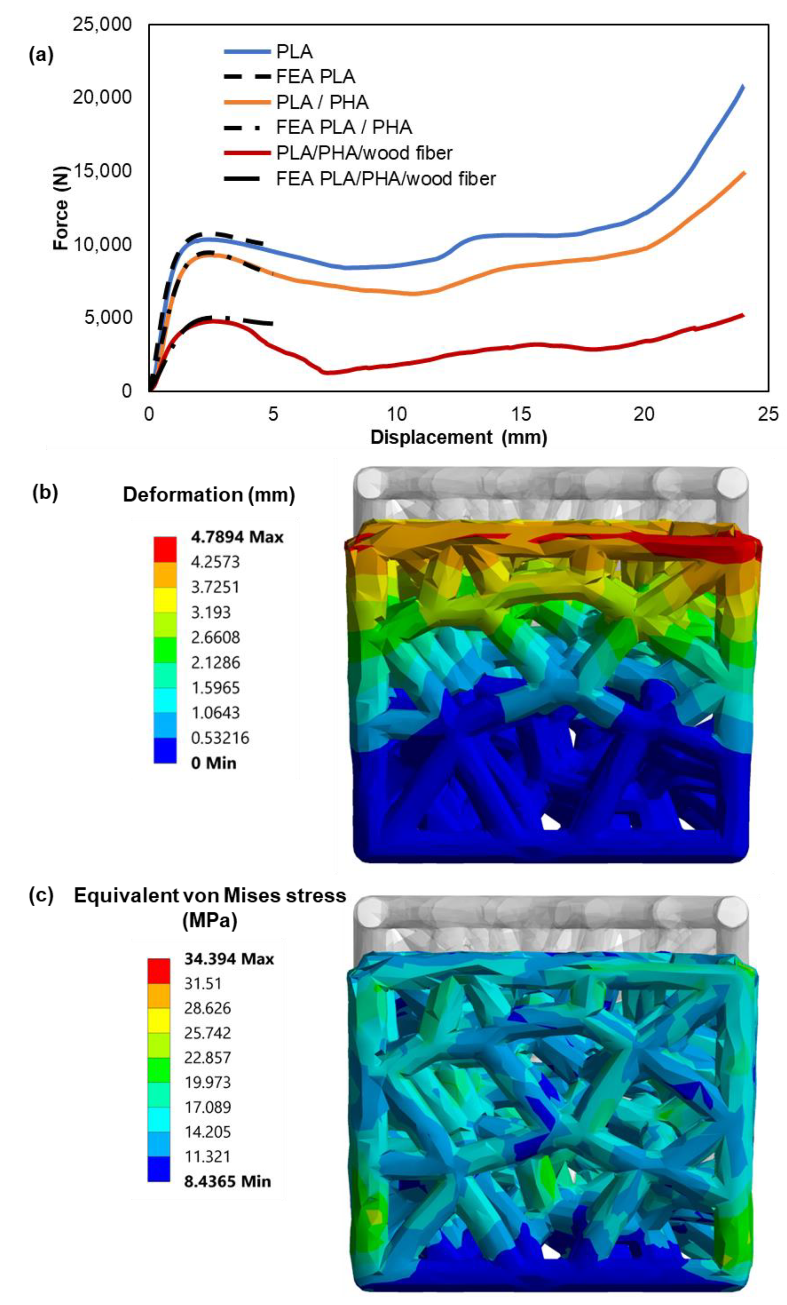
4.3. Characterization of the Mechanical Behavior of the Filaments and 3D-Printed Voronoi Lattice Structures

The mechanical behavior of the neat PLA, the PLA/PHA and PLA/PHA with wood fibers was evaluated by nanoindentation and compression testing. Nanoindentation testing was used to determine the hardness and modulus of elasticity of the PLA composites that were suitable for 3D printing. The nanoindentation tests were performed on the extruded filaments to evaluate the influence of the addition of PHA and wood fibers into the PLA matrix. The results were also used as input for an FE analysis of the mechanical behavior of the nanocomposite materials under study. A deterioration of the elastic moduli of PLA after the incorporation of PHA and PHA/wood fiber is noticeable in the results of the nanoindentation tests. In Figure 11, the representative indentation load–depth curves are illustrated as measured from the nanoindentation. According to the results of the nanoindentation testing, a softening effect that occurred with the introduction of PHA into PLA can be clearly noticed.
The stress–strain response was assessed by the optimal curve fitting force–depth results that matched the nanoindentation experimental data. The FEA results revealed the values of the elasticity moduli for both the PLA and the PLA composite specimens. Table 4 shows this convergence between FEA and the nanoindentation results for all of the PLA samples. Figure 12 illustrates the FEM-extracted stress–strain laws of the PLA specimens. The results show a significant decrease in strength for the wood fiber-reinforced PLA specimens. The PLA/PHA revealed a slightly modified elastic modulus and strength compared to the other nanocomposites. Considering these results, it can be concluded that the wood fibers affected the specimens’ mechanical properties and their overall stress–strain behavior. Furthermore, the experimental nanoindentation technique assisted by FEA has proven to be a very successful method for determining the mechanical behavior of PLA composites.
The compression sequence of the 3D-printed lattice structures is illustrated in Figure 13. A repeated behavior is observed across the specimens which can be distinguished into three separate stages. The first is the elastic zone where the structure is deformed elastically, followed by a long plateau region where the rods of the structure progressively buckle and collapse up until the densification strain [61,62]. At this point, all the cells of the Voronoi have completely collapsed and the densification portion begins as the bulk material is compressed [63]. The failure mechanism of the rods can be attributed to buckling and layer delamination, a behavior that is characteristic of 3D-printed structures [61,64]. The verified material model from the FEA-supported nanoindentation method has been introduced into the FE model for the compression performance of the Voronoi structures. In addition, a computational model was also employed in order to evaluate the stress response of the 3D-printed specimens under compression. This model was developed using the finite element software ANSYS. Initial material values of the stress–strain curves of the 3D materials extracted from nanoindentation tests were introduced in the FEA model. On the top plate of each Voronoi structure, a vertical velocity was applied in steps and the reaction force was obtained at the bottom, which was considered with a fixed boundary condition. The values of this vertical displacement were acquired by the experimental results. Considering the deformation, forces were determined and compared to the experimental ones.
Meshing was generated using a hexahedral for the top compression plate and tetrahedral elements for complex geometries. In Figure 14a, the finite element analysis (FEA) results of force-displacement behavior are demonstrated, revealing a good correlation between the experimental compression tests and the force-displacement data generated by FEA simulations for the 3D-printed specimens. It is worth mentioning that at larger displacements, the experimental curves start to deviate more from the FEA simulation because the 3D printing defects play a larger role in the bending response.
The material model parameters were examined to minimize the difference between the simulated and the experimental force-displacement data. Therefore, the results of the deformation and the equivalent von Mises stress distribution on the 3D-printed Voronoi lattice structures under compressive load, as shown in Figure 14b,c, may accurately indicate the high-stress regions of the structures. Based on the mechanical test results, it can be established that the computationally generated (FEA) compression test data, assisted by the actual measurements could be an effective method to characterize the mechanical deformation behavior of 3D-printed Voronoi structures.

5. Conclusions

A comprehensive strategy of designing and 3D printing a biomimetic Voronoi lattice has been the focus of the present paper. Specialized methodological tools (AskNature, Biomimetic Design Spiral) assisted in the effort of identifying the shell of the sea urchin P. lividus as a potential source of inspiration. Scanning electron microscopy analysis of the shell reveals a porous, foam-like microstructure, also known as the stereom, which can be most efficiently described by a 3D Voronoi diagram. The structure was transferred into a parametric digital model with the aid of CAD software (Rhinoceros 3D) and algorithmic modelling tools (Grasshopper 3D) that can be customized through a series of parameters, the most important of which are node count, trabeculae radius and geometry smoothness. An advantage of such a design approach is that customized design iterations can be created on demand, depending on the application requirements.
FFF technology was implemented for the fabrication of cubic physical models. Rod length (determined by the node count) and thickness determine the success of the 3D printing process. Outer wall speed and layer thickness also influence print quality.
The FFF process is characterized by certain limitations, such as the need for additional supports which can render the process overly complex and time-, material-, and energy-wasteful. To overcome this need, the design parameters of the biologically inspired parametric model were adapted to the process constraints. To verify the reproducibility of the structure, additional samples were printed with different filament materials—a PLA/PHA compound and a PLA/PHA/wood fiber composite. It was observed in all printed samples that supportless overhangs create minor layer drooping issues, a flaw that can be considered intrinsic to the FFF technology. Overall, though, these flaws do not affect the structural integrity of the printed lattice. The successful 3D printing results indicate that the proposed biomimetic design and manufacturing strategy can find application in a variety of sustainable filament materials. Nanoindentation testing revealed a decline in the elastic moduli of PLA after the incorporation of PHA and PHA/wood fiber. FEA results validate the above effect. FEM-extracted stress–strain laws of the PLA samples demonstrate a considerably higher elastic modulus and strength compared to the PLA/PHA/wood fiber composite and a marginal change in the strength of the PLA/PHA compound. Furthermore, the FEA results of the force-displacement behavior of the biomimetic Voronoi structures agree with the experimental compression results with significant accuracy. It can be concluded that a combination of computational (FEA) and physical testing can characterize the mechanical performance of 3D-printed Voronoi structures effectively.

Author Contributions

Conceptualization, A.E. and Ι.S.; methodology, A.E., I.S. and D.T.; software, A.E., I.S. and K.T.; investigation, A.E. and E.K.T.; visualization, A.E.; writing—original draft preparation, A.E. and K.T.; supervision, I.S. and D.T.; funding acquisition, A.E.; validation, E.K.T. formal analysis, A.E. and E.K.T.; data curation, A.E., E.K.T. and K.T. writing—review and editing, I.S. and D.T. project administration, I.S. All authors have read and agreed to the published version of the manuscript.

Funding

The research is conducted in the operating framework of the Center of Research Innovation and Excellence of University of Thessaly (Invitation to submit applications for the grant of scholarships to doctoral candidates of University of Thessaly) and was funded by the Special Account of Research Grants of University of Thessaly.

Data Availability Statement

Not applicable.

Conflicts of Interest

The authors declare no conflict of interest.

References

  1. Benyus, J.M. Biomimicry: Innovation Inspired by Nature; Harper Perennial: New York, NY, USA, 2002; ISBN 978-0-06-053322-9. [Google Scholar]
  2. Sharma, S.; Sarkar, P. Biomimicry: Exploring Research, Challenges, Gaps, and Tools. In Research into Design for a Connected World; Chakrabarti, A., Ed.; Springer: Singapore, 2019; Volume 134, pp. 87–97. ISBN 9789811359736. [Google Scholar]
  3. Symeonidou, Ι.; Efstathiadis, A. Biomimetic Principles for Energy Efficiency in Buildings. In Proceedings of the 8th International Conference on Energy in Buildings 2019, Athens, Greece, 28 September 2019; pp. 33–42, ISBN 978-84-09-22004-5. [Google Scholar]
  4. Nagel, J.K.S.; Stone, R.B.; McAdams, D.A. An Engineering-to-Biology Thesaurus for Engineering Design. In Proceedings of the International Design Engineering Technical Conferences and Computers and Information in Engineering Conference, Montreal, QC, Canada, 15–18 August; pp. 117–128.
  5. Hooker, G.; Smith, E. Asknature and the biomimicry taxonomy. Insight 2016, 19, 46–49. [Google Scholar] [CrossRef]
  6. Institute, T.B. The Power of the Biomimicry Design Spiral. Available online: https://biomimicry.org/biomimicry-design-spiral/ (accessed on 3 October 2021).
  7. Efstathiadis, A.; Symeonidou, I. High Performance Biological Structures. In Proceedings of the 4th International Conference for Biodigital Architecture & Genetics, Barcelona, Spain, 3–5 June 2020; pp. 22–33, ISBN 978-84-09-22004-5. [Google Scholar]
  8. Behera, R.P.; Le Ferrand, H. Impact-Resistant Materials Inspired by the Mantis Shrimp’s Dactyl Club. Matter 2021, 4, 2831–2849. [Google Scholar] [CrossRef]
  9. Rivera, J.; Hosseini, M.S.; Restrepo, D.; Murata, S.; Vasile, D.; Parkinson, D.Y.; Barnard, H.S.; Arakaki, A.; Zavattieri, P.; Kisailus, D. Toughening Mechanisms of the Elytra of the Diabolical Ironclad Beetle. Nature 2020, 586, 543–548. [Google Scholar] [CrossRef] [PubMed]
  10. Li, X.W.; Ji, H.M.; Yang, W.; Zhang, G.P.; Chen, D.L. Mechanical Properties of Crossed-Lamellar Structures in Biological Shells: A Review. J. Mech. Behav. Biomed. Mater. 2017, 74, 54–71. [Google Scholar] [CrossRef] [PubMed]
  11. Yao, H.; Dao, M.; Imholt, T.; Huang, J.; Wheeler, K.; Bonilla, A.; Suresh, S.; Ortiz, C. Protection Mechanisms of the Iron-Plated Armor of a Deep-Sea Hydrothermal Vent Gastropod. Proc. Natl. Acad. Sci. USA 2010, 107, 987–992. [Google Scholar] [CrossRef] [Green Version]
  12. Baur, B. Vermeij G.J. 1993. A Natural History of Shells. Princeton University Press, Princeton, 207 Pp., US$29.95 (Hardback). ISBN: 0-691-08596-X. J. Evol. Biol. 1995, 8, 536. [Google Scholar] [CrossRef]
  13. Grunenfelder, L.K.; Suksangpanya, N.; Salinas, C.; Milliron, G.; Yaraghi, N.; Herrera, S.; Evans-Lutterodt, K.; Nutt, S.R.; Zavattieri, P.; Kisailus, D. Bio-Inspired Impact-Resistant Composites. Acta Biomater. 2014, 10, 3997–4008. [Google Scholar] [CrossRef]
  14. Nordin, A.; Hopf, A.; Motte, D. Generative Design Systems for the Industrial Design of Functional Mass Producible Natural-Mathematical Forms. In Proceedings of the 5th International Congress of International Association of Societies of Design Research, IASDR13, Tokyo, Japan, 26–30 August 2013; pp. 2931–2941. [Google Scholar]
  15. Aish, R.; Woodbury, R. Multi-Level Interaction in Parametric Design. In Smart Graphics; Butz, A., Fisher, B., Krüger, A., Olivier, P., Eds.; Lecture Notes in Computer Science; Springer Berlin Heidelberg: Berlin/Heidelberg, Germany, 2005; Volume 3638, pp. 151–162. ISBN 978-3-540-28179-5. [Google Scholar]
  16. Bertacchini, F.; Bilotta, E.; Demarco, F.; Pantano, P.; Scuro, C. Multi-Objective Optimization and Rapid Prototyping for Jewelry Industry: Methodologies and Case Studies. Int. J. Adv. Manuf. Technol. 2021, 112, 2943–2959. [Google Scholar] [CrossRef]
  17. Eckert, C.; Kelly, I.; Stacey, M. Interactive Generative Systems for Conceptual Design: An Empirical Perspective. Artif. Intell. Eng. Des. Anal. Manuf. 1999, 13, 303–320. [Google Scholar] [CrossRef] [Green Version]
  18. Bates, S.R.G.; Farrow, I.R.; Trask, R.S. 3D Printed Polyurethane Honeycombs for Repeated Tailored Energy Absorption. Mater. Des. 2016, 112, 172–183. [Google Scholar] [CrossRef]
  19. Kladovasilakis, N.; Tsongas, K.; Karalekas, D.; Tzetzis, D. Architected Materials for Additive Manufacturing: A Comprehensive Review. Materials 2022, 15, 5919. [Google Scholar] [CrossRef] [PubMed]
  20. Kladovasilakis, N.; Tsongas, K.; Tzetzis, D. Finite Element Analysis of Orthopedic Hip Implant with Functionally Graded Bioinspired Lattice Structures. Biomimetics 2020, 5, 44. [Google Scholar] [CrossRef] [PubMed]
  21. Yang, Y.; Song, X.; Li, X.; Chen, Z.; Zhou, C.; Zhou, Q.; Chen, Y. Recent Progress in Biomimetic Additive Manufacturing Technology: From Materials to Functional Structures. Adv. Mater. 2018, 30, 1706539. [Google Scholar] [CrossRef] [PubMed]
  22. Kladovasilakis, N.; Tsongas, K.; Tzetzis, D. Mechanical and FEA-Assisted Characterization of Fused Filament Fabricated Triply Periodic Minimal Surface Structures. J. Compos. Sci. 2021, 5, 58. [Google Scholar] [CrossRef]
  23. Kladovasilakis, N.; Tsongas, K.; Kostavelis, I.; Tzovaras, D.; Tzetzis, D. Effective Mechanical Properties of Additive Manufactured Strut-Lattice Structures: Experimental and Finite Element Study. Adv. Eng. Mater. 2022, 24, 2100879. [Google Scholar] [CrossRef]
  24. Kladovasilakis, N.; Charalampous, P.; Tsongas, K.; Kostavelis, I.; Tzovaras, D.; Tzetzis, D. Influence of Selective Laser Melting Additive Manufacturing Parameters in Inconel 718 Superalloy. Materials 2022, 15, 1362. [Google Scholar] [CrossRef]
  25. Kladovasilakis, N.; Tsongas, K.; Kostavelis, I.; Tzovaras, D.; Tzetzis, D. Effective Mechanical Properties of Additive Manufactured Triply Periodic Minimal Surfaces: Experimental and Finite Element Study. Int. J. Adv. Manuf. Technol. 2022, 121, 7169–7189. [Google Scholar] [CrossRef]
  26. Yan, X.; Bethers, B.; Chen, H.; Xiao, S.; Lin, S.; Tran, B.; Jiang, L.; Yang, Y. Recent Advancements in Biomimetic 3D Printing Materials with Enhanced Mechanical Properties. Front. Mater. 2021, 8, 518886. [Google Scholar] [CrossRef]
  27. Song, X.; Tetik, H.; Jirakittsonthon, T.; Parandoush, P.; Yang, G.; Lee, D.; Ryu, S.; Lei, S.; Weiss, M.L.; Lin, D. Biomimetic 3D Printing of Hierarchical and Interconnected Porous Hydroxyapatite Structures with High Mechanical Strength for Bone Cell Culture. Adv. Eng. Mater. 2019, 21, 1800678. [Google Scholar] [CrossRef] [Green Version]
  28. Gong, P.; Zhai, S.; Lee, R.; Zhao, C.; Buahom, P.; Li, G.; Park, C.B. Environmentally Friendly Polylactic Acid-Based Thermal Insulation Foams Blown with Supercritical CO2. Ind. Eng. Chem. Res. 2018, 57, 5464–5471. [Google Scholar] [CrossRef]
  29. Lehmhus, D.; Vesenjak, M.; Schampheleire, S.; Fiedler, T. From Stochastic Foam to Designed Structure: Balancing Cost and Performance of Cellular Metals. Materials 2017, 10, 922. [Google Scholar] [CrossRef] [PubMed] [Green Version]
  30. Maiti, A.; Small, W.; Lewicki, J.P.; Weisgraber, T.H.; Duoss, E.B.; Chinn, S.C.; Pearson, M.A.; Spadaccini, C.M.; Maxwell, R.S.; Wilson, T.S. 3D Printed Cellular Solid Outperforms Traditional Stochastic Foam in Long-Term Mechanical Response. Sci. Rep. 2016, 6, 24871. [Google Scholar] [CrossRef] [PubMed] [Green Version]
  31. Dumas, J.; Hergel, J.; Lefebvre, S. Bridging the Gap: Automated Steady Scaffoldings for 3D Printing. ACM Trans. Graph. 2014, 33, 1–10. [Google Scholar] [CrossRef] [Green Version]
  32. Strano, G.; Hao, L.; Everson, R.M.; Evans, K.E. A New Approach to the Design and Optimisation of Support Structures in Additive Manufacturing. Int. J. Adv. Manuf. Technol. 2013, 66, 1247–1254. [Google Scholar] [CrossRef]
  33. Khosravani, M.R.; Zolfagharian, A.; Jennings, M.; Reinicke, T. Structural Performance of 3D-Printed Composites under Various Loads and Environmental Conditions. Polym. Test. 2020, 91, 106770. [Google Scholar] [CrossRef]
  34. Wang, B.; Sun, L.; Pan, B. Mapping Internal Deformation Fields in 3D Printed Porous Structure with Digital Volume Correlation. Polym. Test. 2019, 78, 105945. [Google Scholar] [CrossRef] [Green Version]
  35. Khosravani, M.R.; Reinicke, T. Fracture Studies of 3D-Printed PLA-Wood Composite. Procedia Struct. Integr. 2022, 37, 97–104. [Google Scholar] [CrossRef]
  36. Fico, D.; Rizzo, D.; De Carolis, V.; Montagna, F.; Palumbo, E.; Corcione, C.E. Development and Characterization of Sustainable PLA/Olive Wood Waste Composites for Rehabilitation Applications Using Fused Filament Fabrication (FFF). J. Build. Eng. 2022, 56, 104673. [Google Scholar] [CrossRef]
  37. Grigora, M.-E.; Terzopoulou, Z.; Tsongas, K.; Bikiaris, D.N.; Tzetzis, D. Physicochemical Characterization and Finite Element Analysis-Assisted Mechanical Behavior of Polylactic Acid-Montmorillonite 3D Printed Nanocomposites. Nanomaterials 2022, 12, 2641. [Google Scholar] [CrossRef]
  38. Grigora, M.-E.; Terzopoulou, Z.; Tsongas, K.; Klonos, P.; Kalafatakis, N.; Bikiaris, D.N.; Kyritsis, A.; Tzetzis, D. Influence of Reactive Chain Extension on the Properties of 3D Printed Poly(Lactic Acid) Constructs. Polymers 2021, 13, 1381. [Google Scholar] [CrossRef]
  39. Mechanical Design in Organisms; Wainwright, S.A. (Ed.) Edward Arnold: London, UK, 1976; ISBN 978-0-7131-2502-3. [Google Scholar]
  40. Müter, D.; Sørensen, H.O.; Oddershede, J.; Dalby, K.N.; Stipp, S.L.S. Microstructure and Micromechanics of the Heart Urchin Test from X-Ray Tomography. Acta Biomater. 2015, 23, 21–26. [Google Scholar] [CrossRef] [PubMed]
  41. A/Λ.Σ.-ΕΛ.AΚΤ./ΔΕΛAΛ. Available online: https://alieia.hcg.gr/fishes/OSTRAKA/OSTRAKA_KAT.php (accessed on 29 January 2021).
  42. Boudouresque, C.F.; Verlaque, M. Ecology of Paracentrotus Lividus. In Developments in Aquaculture and Fisheries Science; Elsevier: Amsterdam, The Netherlands, 2001; Volume 32, pp. 177–216. ISBN 978-0-444-50390-9. [Google Scholar]
  43. Fantini, M.; Curto, M. Interactive Design and Manufacturing of a Voronoi-Based Biomimetic Bone Scaffold for Morphological Characterization. Int. J. Interact. Des. Manuf. IJIDeM 2018, 12, 585–596. [Google Scholar] [CrossRef]
  44. Dendro. Available online: https://www.food4rhino.com/app/dendro (accessed on 18 March 2021).
  45. Posted by Daniel Piker on December 22, 2012 at 2:36 pm; Blog, V. Topologizer/Network CleanUp. Available online: https://www.grasshopper3d.com/profiles/blogs/topologizer-network-cleanup (accessed on 18 March 2021).
  46. Klonos, P.A.; Papadopoulos, L.; Tzetzis, D.; Kyritsis, A.; Papageorgiou, G.Z.; Bikiaris, D.N. Thermal, Nanoindentation and Dielectric Study of Nanocomposites Based on Poly(Propylene Furanoate) and Various Inclusions. Mater. Today Commun. 2019, 20, 100585. [Google Scholar] [CrossRef]
  47. Papadopoulos, L.; Terzopoulou, Z.; Vlachopoulos, A.; Klonos, P.A.; Kyritsis, A.; Tzetzis, D.; Papageorgiou, G.Z.; Bikiaris, D. Synthesis and Characterization of Novel Polymer/Clay Nanocomposites Based on Poly (Butylene 2,5-Furan Dicarboxylate). Appl. Clay Sci. 2020, 190, 105588. [Google Scholar] [CrossRef]
  48. Tzetzis, D.; Tsongas, K.; Mansour, G. Determination of the Mechanical Properties of Epoxy Silica Nanocomposites through FEA-Supported Evaluation of Ball Indentation Test Results. Mater. Res. 2017, 20, 1571–1578. [Google Scholar] [CrossRef] [Green Version]
  49. Tsongas, K.; Tzetzis, D.; Karantzalis, A.; Banias, G.; Exarchos, D.; Ahmadkhaniha, D.; Zanella, C.; Matikas, T.; Bochtis, D. Microstructural, Surface Topology and Nanomechanical Characterization of Electrodeposited Ni-P/SiC Nanocomposite Coatings. Appl. Sci. 2019, 9, 2901. [Google Scholar] [CrossRef] [Green Version]
  50. Mansour, G.; Zoumaki, M.; Tsongas, K.; Tzetzis, D. Microstructural and Finite Element Analysis—Assisted Nanomechanical Characterization of Maize Starch Nanocomposite Films. Mater. Res. 2021, 24, e20200409. [Google Scholar] [CrossRef]
  51. Sanja, T.; Conides, A.; Dupcic Radic, I.; Glamuzina, B. Growth, Size Class Frequency and Reproduction of Purple Sea Urchin, -Paracentrotus Lividus (Lamarck, 1816) in Bistrina Bay (Adriatic Sea, Croatia). Acta Adriat. 2010, 51, 67–77. [Google Scholar] [CrossRef]
  52. Hotchkiss, F. A “Rays-as-Appendages” Model for the Origin of Pentamerism in Echinoderms. Paleobiology. 1998, 24, 200–214. [Google Scholar] [CrossRef]
  53. Telford, M. Domes, Arches and Urchins: The Skeletal Architecture of Echinoids (Echinodermata). Zoomorphology 1985, 105, 114–124. [Google Scholar] [CrossRef]
  54. Moss, M.L.; Meehan, M.M. Sutural Connective Tissues in the Test of an Echinoid: Arbacia Punctulata. Acta Anat. 1967, 66, 279–304. [Google Scholar] [PubMed]
  55. Kidwell, S.M.; Baumiller, T. Experimental Disintegration of Regular Echinoids: Roles of Temperature, Oxygen, and Decay Thresholds. Paleobiology 1990, 16, 247–271. [Google Scholar] [CrossRef]
  56. Ellers, O.; Johnson, A.S.; Moberg, P.E. Structural Strengthening of Urchin Skeletons by Collagenous Sutural Ligaments. Biol. Bull. 1998, 195, 136–144. [Google Scholar] [CrossRef] [PubMed] [Green Version]
  57. Smith, A.B. Stereom Microstructure of the Echinoid Test. Spec. Pap. Palaeontol. 1980, 25, 1–81. [Google Scholar]
  58. Aurenhammer, F. Voronoi Diagrams—A Survey of a Fundamental Geometric Data Structure. ACM Comput. Surv. 1991, 23, 345–405. [Google Scholar] [CrossRef]
  59. Fantini, M.; Curto, M.; De Crescenzio, F. A Method to Design Biomimetic Scaffolds for Bone Tissue Engineering Based on Voronoi Lattices. Virtual Phys. Prototyp. 2016, 11, 77–90. [Google Scholar] [CrossRef]
  60. Okabe, A.; Boots, B.; Sugihara, K. Nearest Neighbourhood Operations with Generalized Voronoi Diagrams: A Review. Int. J. Geogr. Inf. Syst. 1994, 8, 43–71. [Google Scholar] [CrossRef]
  61. Wang, S.; Ding, Y.; Yu, F.; Zheng, Z.; Wang, Y. Crushing Behavior and Deformation Mechanism of Additively Manufactured Voronoi-Based Random Open-Cell Polymer Foams. Mater. Today Commun. 2020, 25, 101406. [Google Scholar] [CrossRef]
  62. Almonti, D.; Baiocco, G.; Tagliaferri, V.; Ucciardello, N. Design and Mechanical Characterization of Voronoi Structures Manufactured by Indirect Additive Manufacturing. Materials 2020, 13, 1085. [Google Scholar] [CrossRef] [Green Version]
  63. Li, Q.M.; Magkiriadis, I.; Harrigan, J.J. Compressive Strain at the Onset of Densification of Cellular Solids. J. Cell. Plast. 2006, 42, 371–392. [Google Scholar] [CrossRef]
  64. Ben Ali, N.; Khlif, M.; Hammami, D.; Bradai, C. Mechanical and Morphological Characterization of Spherical Cell Porous Structures Manufactured Using FDM Process. Eng. Fract. Mech. 2019, 216, 106527. [Google Scholar] [CrossRef]
Figure 1. SEM cross-section images of the (a) PLA filament, (b) PLA/PHA filament and (c) PLA/PHA/wood fiber filament.
Jcs 07 00003 g001
Figure 2. Overview of a sea urchin’s (Paracentrotus lividus) structure: (a) photograph of a fresh urchin; (b) dried urchin test with its spikes removed; (c) the plates of the sample under optical microscopy; (d) scanning electron micrography of the sample’s stereom.
Jcs 07 00003 g002
Figure 3. The formation of an ordinary Voronoi diagram from a finite set of points within a finite 2D space: (a) two-dimensional Cartesian space with a finite set of points; (b) expanding circles drawn around each center point; (c) circles coming into contact and linear boundaries are formed; (d) no further expansion is possible and convex polygons are formed.
Jcs 07 00003 g003
Figure 4. Formation of 3D Voronoi diagram: (a) bounding box with a finite set of points; (b) a 3D Voronoi diagram has formed as spheres expanded around each point until face boundaries are formed; (c) individual polyhedron cell.
Jcs 07 00003 g004
Figure 5. The Grasshopper definition on the visual programming environment’s canvas.
Jcs 07 00003 g005
Figure 6. Top-level workflow diagram of the interactive, parametric design process of a biomimetic Voronoi lattice. The most important user-defined parameters are found in the grey boxes.
Jcs 07 00003 g006
Figure 7. Second level workflow diagram of the algorithmic generation of the Voronoi lattice. Dependent components are shown in white, while independent ones (user-defined parameters) are shown in grey.
Jcs 07 00003 g007
Figure 8. Four examples of Voronoi models with different sets of parameters: (a) the baseline model (Model A) with a node count of 60, rod radius 1.8 mm and smoothness width 1; (b) rod radius is changed to 2.4 mm in Model B; (c) node count parameter is raised to 120 in Model C while the rest are the same as for the baseline one; (d) smoothness width is set to 6 in Model D with the rest unchanged.
Jcs 07 00003 g008
Figure 9. Long and thin trabeculae were susceptible to poor bonding and failure during 3D printing.
Jcs 07 00003 g009
Figure 10. Comparison between: (a) the digital model of the biomimetic Voronoi lattice; (b) the 3D-printed sample using PLA filament; (c) the printed sample with the PLA/PHA compound filament; (d) the printed sample with the PLA/PHA/wood fiber composite filament.
Jcs 07 00003 g010
Figure 11. Comparison of load–depth nanoindentation curves of PLA composites along with the FEA-generated verification results.
Jcs 07 00003 g011
Figure 12. FEA-generated stress–strain curves of the PLA composites.
Jcs 07 00003 g012
Figure 13. The compression stages of the Voronoi structures illustrated for: (a) neat PLA; (b) PLA/PHA compound.
Jcs 07 00003 g013
Figure 14. (a) Experimental load–displacement response for the Voronoi lattice structures curve-fitted by FEA generated data, (b) vertical deformation and (c) stress distribution of the Voronoi structure under compression load, utilizing the PLA material properties in the FE model.
Jcs 07 00003 g014
Table 1. Design parameter value changes for Figure 8 models.
Design ParameterModel AModel BModel CModel D
Node Count606012060
Rod Radius (mm)1.82.41.81.8
Smooth Width 11116
1 Integer that describes the scale of the smoothing process.
Table 2. Complete set of design parameters for the 3D-printed sample.
Design ParameterValue
L × W × H40 × 40 × 40 mm3
Node Count60
Seed10
Tolerance0.5
Curve Radius1.8 mm
Voxel Size0.2 mm
Bandwidth7
Isovalue0
Adaptivity0
Smooth Width1
Type2 (mean)
Iterations1
Table 3. Parameters of the FFF process used for fabrication of the Voronoi lattice structure.
Printer ParameterValue
Nozzle size0.4 mm
MaterialsPLA—PLA/PHA—PLA/PHA Wood Fiber
Layer Thickness0.2 mm
Wall Thickness0.8 mm
Infill PatternLines
Infill Density100%
Outer Wall Speed15 mm/s
Inner Wall Speed30 mm/s
Infill Speed30 mm/s
Printing Temp.205 °C
Build Plate Temp.55 °C
SupportNo
Print Time≈6h
Table 4. Comparison of the elastic moduli of nanoindentation of the PLA, PLA/PHA and PLA/PHA/wood fiber composites.
FilamentE modulus
Nanoindentation
(MPa)
E modulus
Nanoindentation FEA
(MPa)
PLA3782.57 ± 77.663733
PLA/PHA3242.83 ± 50.323122
PLA/PHA/wood fiber2515.88 ± 160.872313
Disclaimer/Publisher’s Note: The statements, opinions and data contained in all publications are solely those of the individual author(s) and contributor(s) and not of MDPI and/or the editor(s). MDPI and/or the editor(s) disclaim responsibility for any injury to people or property resulting from any ideas, methods, instructions or products referred to in the content.

