Article

Interaction between Micro-Amplitude Vibration and Thrust Force in Ultrasonic-Vibration-Assisted Drilling of Glass-Fiber-Reinforced Plastics

School of Mechanical Engineering, Nanjing University of Science and Technology, Nanjing 210094, China
J. Compos. Sci. 2023, 7(1), 4; https://doi.org/10.3390/jcs7010004
Submission received: 25 November 2022 / Revised: 16 December 2022 / Accepted: 20 December 2022 / Published: 26 December 2022
(This article belongs to the Section Composites Manufacturing and Processing)

Abstract

:
This research intends to investigate the effect and potential of the ultrasonic vibration of tools for drilling glass-fiber-reinforced plastics (GFRPs), especially with the aim of minimizing the thrust force. As an important parameter to characterize the vibration intensity, the vibration amplitude has a significant effect on the thrust force in the ultrasonic-vibration-assisted drilling (UVD) of GFRPs. It has been observed that the thrust force also influences the vibration amplitude, which may eventually result in a failure of the vibration. In this study, a method for the in-process measurement of the vibration amplitude was introduced to enable the investigation of the interaction between the thrust force and vibration amplitude in UVD. It was investigated how variations of the thrust force and vibration amplitude influence each other from holistic and individual perspectives. The critical condition was identified to ensure a sufficient ultrasonic vibration effect during drilling. Additionally, UVD experiments with different vibration amplitudes were carried out. The interaction between thrust force and vibration amplitude in UVD was revealed. It can be concluded that the combination of a moderate thrust force, low vibration amplitude reduction ratio, and high vibration amplitude increases the thrust force reduction ratio and secondly that an excessive thrust force undermines the effect of ultrasonic vibration. This provides an in-depth understanding of the interaction between vibration and thrust force in UVD, and helps to further improve the effect of ultrasonic vibration.

1. Introduction

Fiber-reinforced plastics, such as carbon-fiber-reinforced plastics (CFRPs) and glass-fiber-reinforced plastics (GFRPs), have been widely applied in the aerospace and automotive industries due to their superior physical and mechanical properties, such as a high specific strength and stiffness, low thermal expansion coefficient, and high wear resistance [1,2,3]. Fiber-reinforced plastic parts are normally manufactured in a net shape, and bolted joints are inevitable for assembly to form a functional unit. The hole quality has a significant effect on the joint performance, which will inevitably affect the service life. Due to the anisotropy property of fiber-reinforced plastics and the high thrust force during the hole-making process, some drawbacks (e.g., matrix cracking, fiber/matrix debonding, fiber peel-up and push-out, and delamination) frequently appear at the entrance, inner surface, and exit of the drilled hole, which have a negative impact on the assembly quality [4,5,6,7,8].
As a hybrid machining method, the ultrasonic-vibration-assisted drilling (UVD) technique has been investigated for hole-making in fiber-reinforced plastics. Some studies have demonstrated that UVD has a positive effect on the hole quality compared with conventional drilling (CD) because ultrasonic vibration is conducive to reducing thrust forces. Aoki et al. [9] proposed using ultrasonic vibration to prevent delamination during the drilling of GFRPs. The experimental results showed that the occurrence of delamination becomes less compared with conventional machining. Mehbudi et al. [10] designed a setup to superimpose the ultrasonic vibration on a rotating drill bit. The drilling experiments with ultrasonic vibration were conducted and compared with conventional drilling. The results showed that ultrasonic vibration has a positive effect on reducing the thrust force and drilling-induced delamination, and the effect of the input variables on delamination was very similar to their effect on thrust force, which was due to the propagation of delamination in the thrust force [11]. Gao et al. [12] designed an ultrasonic vibration hand-held drill for CFRPs’ hole-making. The drilling experimental results indicated that the thrust force decreased by 23% and the peel-off and delamination defects were significantly reduced. Moreover, Gao et al. [13] studied the ultrasonic vibration drilling of tapered countersink holes. The experimental results revealed that an 8–21.5% reduction in thrust force was obtained, and the hole quality correspondingly improved. Georgi et al. [14] revealed the interaction between the tool and workpiece in UVD with a kinematic analysis and found that the uncut chip thickness could be adjusted, and shorter chips could be obtained in UVD compared with CD. This phenomenon contributes to thrust force reduction. Huang et al. [15] investigated the effect of ultrasonic vibration on tool wear during the drilling of CFRPs. It was observed that the average width of the flank wear was reduced up to 13% due to the enhanced abilities of material removal and chip evacuation with the assistance of ultrasonic vibration. Tool wear reduction would also have a positive effect on the drilled hole quality. Furthermore, Liu [16,17] and Wang [18] studied the longitudinal-torsional-coupled rotary ultrasonic-vibration-assisted drilling of CFRPs. The results indicated that the thrust force was reduced by about 30%, and the comprehensive damage factor was reduced by more than 18% compared with CD. Zhang et al. [19] investigated variant–dimension UVD for CFRPs. It showed that a better hole quality was obtained with variant–dimension UVD. Based on the reviewed literature, the positive effects of ultrasonic vibration on reducing thrust force and hole defects are obvious.
However, for the cited investigations, the vibration amplitude, which is the main parameter to characterize the ultrasonic vibration effect, was assumed to remain constant during UVD. From preliminary experiments, the author of this paper found that the thrust force also had a negative effect on the vibration amplitude. To ensure the ultrasonic vibration effect, the magnitude of the vibration amplitude should be controlled at a relatively high level. Therefore, the interaction between thrust force and vibration amplitude should be fully understood in UVD. Unfortunately, only a small number of relevant studies have been conducted. Moghaddas et al. [20] presented a technique to measure the vibration amplitude under no load, at the beginning of drilling, in the middle of drilling, and at the end of drilling. The results showed that the thrust force caused a considerable reduction in vibration amplitude during UVD. In this study, harmonic striations were used to measure the vibration amplitude in the middle of drilling. This method was useful for metal drilling, while it was difficult to obtain the vibration amplitude in UVD for fiber-reinforced plastics as the harmonic striations were not clear. Bie et al. [21] tried to indirectly characterize the vibration amplitude with ultrasonic power. The relationship between the ultrasonic power and vibration amplitude was obtained with no load, which may not reflect the relationship during UVD. Hence, a further study should be carried out to clearly reveal the interaction between the thrust force and vibration amplitude.
In this study, the author attempted to clearly reveal the interaction between micro-amplitude vibration and thrust force in the UVD of glass-fiber-reinforced plastics. A measurement method was proposed to enable the in-process measurement of vibration amplitude. Thrust force and vibration amplitude data at different spindle speeds were obtained, as well as vibration amplitude data at extremely high and small thrust forces. The thrust force and vibration amplitude reduction ratios were introduced to better elucidate the interaction. The weakening effect of the thrust force on the vibration amplitude was revealed from a holistic and individual perspective, and some suggestions are given to obtain good vibration effects in UVD.

2. Materials and Methods

2.1. Workpiece Material and Tool

Glass-fiber-reinforced plastic was selected as the workpiece material, which was supplied by McMaster-Carr (Elmhurst, IL, USA). It was made with a flame-retardant resin (polyester). The reinforcement material was fiberglass fabric, of which fiberglass accounted for 50–70%. The workpiece was cut into 100 × 100 mm parts (length and width) via a water-jet machine with a thickness of 12 mm. Other relevant physical and mechanical properties are listed in Table 1.
The tool used was a diamond-coated brad-point drill (Karnasch Professional Tools GmbH, Heddesheim, Germany), which is claimed to be specifically designed for fiber-reinforced plastics machining. The diameter of the diamond-coated brad-point drill was 5 mm.

2.2. Experimental Set-Up

The experimental setup is schematically illustrated in Figure 1. An ultrasonic machine center (DMG Sauer 20, DMG MORI EMEA GmbH, Bielefeld, Germany) was utilized for the hole-making of the GFRPs, and a dedicated fixture was designed to clamp the workpiece. The most direct way to measure the vibration amplitude of the drill bit is through a vibrometer, and the laser beam is placed on the top of the drill bit. However, the drill bit gradually enters the inside of the workpiece during UVD. The laser beam cannot pass through the GFRPs, so the vibration amplitude in the whole drilling process cannot be measured. Therefore, a method for in-process measurement of vibration amplitude via an eddy current sensor was proposed. As shown in the red dotted box in Figure 1, there was a step in the position of the collet. The drill bit was mounted on the tool holder by the collet. An eddy current sensor was installed and adjusted to ensure that the center of the eddy current sensor was at the same height as the step surface. There was a small coil in the eddy current sensor probe, which was controlled by the controller to generate an oscillating electromagnetic field. When approaching the step position, the measured step surface generates an induced current, and a reverse electromagnetic field is generated. When there is ultrasonic vibration, the step moves up and down. The movement of the step affects the strength of the reverse electromagnetic field, which means that there exists a relationship between the vibration amplitude of the step and the degree of the change of the reverse electric field. By calibrating the amplitude of the top of the drill bit in the absence of a load, the relationship between the vibration amplitude of the drill bit and the change degree of the current in the eddy current sensor can be established. Therefore, the in-process measurement of the vibration amplitude could be realized by the eddy current sensor. The vibration of the top of the drill bit was measured first via a laser vibrometer (Sensor head: Polytec OFV 353l; Controller: Polytec OFV 2200) to obtain the relationship between the vibration amplitude and the change degree of the current in the eddy current sensor. The drill bit vibrated in a resonant mode, and the resonant frequency of the vibration system was detected by the ultrasonic machine center’s controller. The resonant frequency was shown in the control panel. An emulsion (Synergy 915) was selected as a coolant. A dynamometer (Kistler 9119AA1), related amplifier (Kistler 5070B), and NI DAQ system were configured to acquire and save the thrust force data.

2.3. Process Parameters

From the preliminary experiments, the variation of the feed rate did not lead to a significant change in the thrust force. Therefore, a constant feed rate was selected, and the magnitude was determined to be 100 mm/min to ensure an appropriate drilling time for data acquisition. The spindle speed was controlled to vary from 500 to 9500 rpm to obtain a large range of thrust forces. Afterwards, comparative experiments (conventional drilling, low-amplitude vibration drilling, and high-amplitude vibration drilling) were carried out in the conditions of small and large thrust forces. The details of the experimental design are shown in Table 2. A total of 24 trials were conducted. For each set of experiments, five holes were drilled, and the average value was used for analysis. When the vibration power was 0, it meant conventional drilling. From experiments No. 1 to 18, the spindle speed increased from 500 to 9500 rpm with 9 levels, which included 9 sets of UVD tests and 9 sets of CD tests. Experiments 19–21 represent three different vibration states (UVD with 100% vibration power, UVD with 50% vibration power, and CD), while the spindle speed was fixed at 10,000 rpm and the feed speed was fixed at 50 mm/min. Experiments 22–24 were similar to experiments 19–21 but with a different spindle speed and feed rate. The vibration frequency indicated by the machine was 22,800 Hz. The amplitude under no load was related to the vibration power setting on the machine. A high-amplitude vibration was obtained with 100% vibration power, while a low-amplitude vibration was obtained with 50% vibration power.

3. Results and Discussion

3.1. Typical Characteristics of Thrust Force and Vibration Amplitude

During ultrasonic-vibration-assisted drilling, the typical variations of the thrust force and the corresponding vibration amplitude are shown in Figure 2. The spindle speed was 1500 rpm, the feed rate was 100 mm/min, and the vibration power was 100%. Figure 2a shows the raw data of the thrust force and vibration amplitude, while Figure 2b shows the corresponding smoothed data to clearly display the fluctuation. The smoothed data were obtained by the moving average method. The vibration amplitude decreased due to the interaction between the drill bit and the workpiece. The thrust force and the vibration amplitude mentioned in Section 3.2 were the average values of the thrust forces and vibration amplitudes, whereas they are the corresponding smoothed values in Section 3.3. The thrust force reduction ratio (TFRR) is the ratio of the force difference between CD and UVD over the force in CD. The vibration amplitude reduction ratio (VARR) is the ratio of the amplitude difference between free vibration and the vibration during drilling over the amplitude during free vibration.

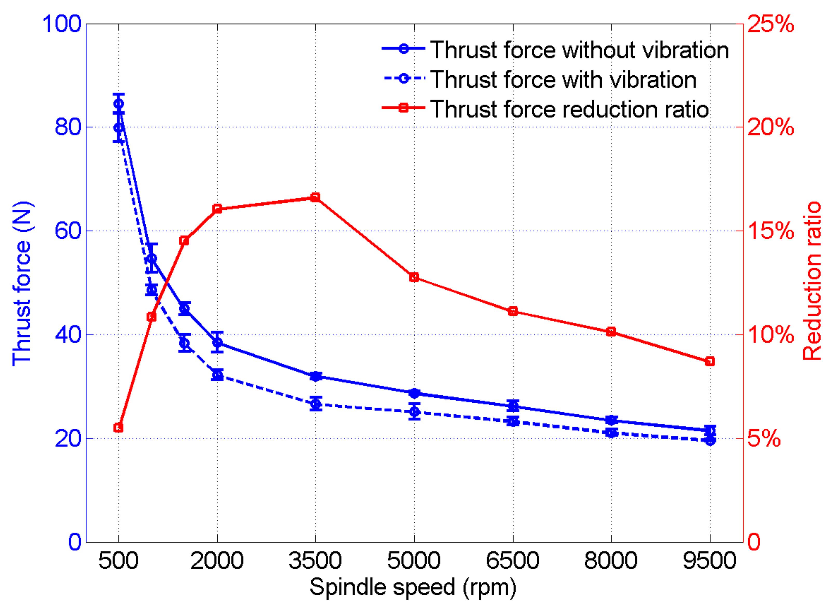
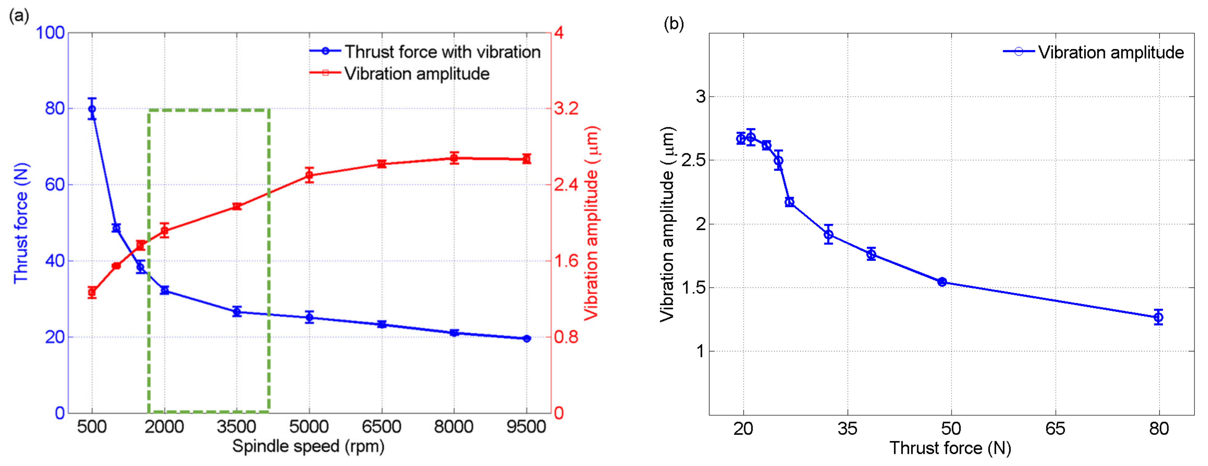
3.2. Interaction between Thrust Force and Vibration Amplitude from a Holistic Perspective

The results of the experiments (Series No.: 1 to 18) are shown in Figure 3, and the error bar represents the standard deviation. In both UVD and CD, the thrust force decreased with an increase in the spindle speed. As the feed rate was fixed at 100 mm/min, the material removed in unit time was constant. With the rise of the spindle speed, the feed distance per revolution decreased, and the material removed per revolution correspondingly decreased, which resulted in a decrease in the thrust force. Moreover, the thrust force in UVD was lower than the thrust force in CD. This result was consistent with existing studies [10,12,13], which means that the assistance of vibration helps to reduce the thrust force as it can form intermittent cutting and dynamically change the cutting angle. However, when it comes to the degree of thrust force reduction, it was found that the TFRR increased first and then decreased as the spindle speed increased from 500 to 9500 rpm, as shown by the red curve in Figure 3. Generally, the vibration parameters are set before drilling, and they are considered to remain constant during drilling. However, this assumption does not coincide with the phenomenon that the TFRR increased first and then decreased.
Furthermore, the thrust force and vibration amplitude in UVD were compared, as shown in Figure 4a,b. The thrust force decreased with the rise of the spindle speed, whereas the amplitude displayed the opposite trend. This clearly indicates that the vibration amplitude was not constant in UVD. Moreover, an increased thrust force reduced the vibration amplitude because the thrust force reacted with the piezoelectric ceramic to weaken the inverse piezoelectric effect, which was utilized to produce the original vibration. The greater the thrust force, the weaker the inverse piezoelectric effect and the smaller the vibration amplitude. Furthermore, the vibration amplitude first rapidly and then slowly decreased with an increase in the thrust force, as shown in Figure 4b. This means that the weakening effect of the thrust force on the inverse piezoelectric effect was not linear.
Although the absolute values of the thrust force and vibration amplitude in UVD monotonically vary, the variations of the TFRR and VARR were not monotonous, as shown in Figure 5. The TFRR increased first and then decreased with the rise of the spindle speed, while the VARR displayed the opposite trend. The TFRR showed an approximate negative correlation with the VARR. The high VARR meant that the weakening effect of the vibration amplitude is obvious, which resulted in a low TFRR. Combining Figure 4a and Figure 5, it was found that the absolute amplitude value could not integrally characterize the ultrasonic vibration effect; the VARR also had an effect on it. The absolute amplitude value was directly determined by the absolute value of the thrust force; therefore, the absolute thrust force value and VARR could be utilized together to characterize the effect of thrust force reduction (i.e., thrust force reduction ratio, or TFRR). As shown in Figure 5, a spindle speed of around 3500 rpm could be considered as a critical value to obtain the maximum TFRR (16.61%). In this critical condition, the absolute thrust force value was moderate and the VARR was small. It can be concluded that a moderate thrust force and a small VARR were conducive to the enhancement of the ultrasonic vibration effect in UVD. If a TFRR > 15% was selected as the critical condition to represent the significant ultrasonic vibration effect, the thrust force needed to be between 25 and 35 N, and the VARR should be smaller than 35%, as shown in the green dotted boxes in Figure 4a and Figure 5.
Further experiments (Series No.: 19 to 24) were carried out to study the effect of the absolute values of vibration amplitude and thrust force on the TFRR, as shown in Figure 6. In Figure 6a, the thrust force is about 17 N, and the VARR is relatively small (between 20% and 35%). The vibration amplitude value was about 2.9 μm at 100% vibration power, and it was about 1.2 μm at 50% vibration power. It can be observed that the larger absolute vibration amplitude value led to a larger TFRR (about 11.6%). In Figure 6b, the thrust force is about 400 N, and the VARR is relatively large (greater than 60%). The vibration amplitude value was about 1.0 μm at 100% vibration power and about 0.7 μm at 50% vibration power. The drill bit vibrated at a low amplitude and high VARR. It can also be found that the larger absolute vibration amplitude value resulted in a larger TFRR (about 1.6%). A comprehensive analysis of Figure 6a,b shows that thrust forces too large or too small could not fully reflect the advantages of ultrasonic vibration. When the thrust force was too small, the action between the drill bit and the workpiece was weak and the effect of ultrasonic vibration could not be fully utilized. When the thrust force was too large, the reaction force suppressed the inverse piezoelectric effect of the piezoelectric ceramics. It seriously weakened the ultrasonic vibration effect, resulting in the thrust force being almost the same for CD and UVD.
From a holistic perspective, the vibration amplitude varied in UVD due to the effect of the thrust force. The vibration amplitude increased with a decrease in the thrust force. A significant ultrasonic vibration effect was obtained in the condition of a moderate thrust force and small VARR. On this basis, a larger absolute value of vibration amplitude can further improve the effect of ultrasonic vibration. Additionally, a thrust force too small or too large undermines the ultrasonic vibration effect.

3.3. Interaction between Thrust Force and Vibration Amplitude from an Individual Perspective

From an individual perspective, the hole-drilling process can be divided into three stages: drilling into the workpiece, stable drilling, and drilling out of the workpiece. During the hole-drilling process, the thrust force was not stable, nor was the vibration amplitude. In Figure 7, the variations of the thrust force and vibration amplitude during each hole-drilling process are presented according to the experimental results (Series No.: 1 to 18). It can be observed that the thrust force was the largest during the stage of drilling into the workpiece, followed by the stage of drilling out of the workpiece, and the thrust force was the smallest during the stable drilling stage. This phenomenon may have been caused by a dynamic change in the actual cutting-edge length in the entrance and exit during the hole-drilling process. In addition, the vibration amplitude was large during free vibration, and the amplitude rapidly decreased when the drill bit came into contact with the workpiece. It can also be found that the values of the vibration amplitude before and after drilling (they all belong to the free vibration condition) were different. Furthermore, when the thrust force was large, the thrust force fluctuation in the hole-drilling process was also relatively large, as well as the vibration amplitude. Based on the above results, it can be derived that adjusting the drilling parameters to appropriately reduce the thrust force at the entrance and exit further enhances the ultrasonic vibration effect. For example, if the spindle speed is increased at the entrance and exit while keeping the feed rate constant, it is expected to further increase the TFRR while maintaining drilling efficiency.

4. Conclusions

In this study, a series of experiments was carried out and a comprehensive analysis was conducted to reveal the interaction between thrust force and vibration amplitude in the ultrasonic-vibration-assisted drilling of glass-fiber-reinforced plastics in depth. The following conclusions can be drawn:
(1)
The vibration amplitude is not constant in UVD, and it increases with a decrease in the thrust force.
(2)
The vibration effect depends not only on the absolute value of the vibration amplitude but also on the absolute thrust force value and vibration amplitude reduction ratio in UVD. A significant ultrasonic vibration effect can be obtained with the combination of a moderate thrust force and small VARR. On this basis, a larger absolute value of vibration amplitude can further improve the effect of ultrasonic vibration.
(3)
A thrust force too small or too large undermines the ultrasonic effect. If a TFRR > 15% is considered the critical condition to represent the significant ultrasonic vibration effect, the thrust force needs to be between 25 and 35 N, and the VARR should be smaller than 35%.
(4)
If the thrust force at the entrance and exit is appropriately reduced by adjusting the drilling parameters in UVD, the ultrasonic vibration effect can be further improved. This means that the TFRR will further increase.
Furthermore, as mentioned above, the reduction of vibration amplitude was due to the thrust force reacting with the piezoelectric ceramic to weaken the inverse piezoelectric effect, which was utilized to produce the original vibration. The thrust force is always present in UVD, no matter what workpiece material is utilized, and the difference is the magnitude of the thrust force. Therefore, it can be inferred that the main conclusions obtained can be extended to other workpiece materials in UVD. In addition to UVD, in other ultrasonic-vibration-assisted machining, such as ultrasonic-vibration-assisted milling and ultrasonic-vibration-assisted grinding, the weakening effect of the vibration should also be taken into account when the cutting force has obvious effects on the vibration amplitude.

Funding

This research was funded by the Fundamental Research Funds for the Central Universities, grant number 30920021106.

Institutional Review Board Statement

Not applicable.

Informed Consent Statement

Not applicable.

Data Availability Statement

Not applicable.

Acknowledgments

The author appreciates the hardware support from the Micro and Precision Engineering research group at KU Leuven.

Conflicts of Interest

The author declares no conflict of interest.

References

  1. Liu, D.F.; Tang, Y.J.; Cong, W.L. A review of mechanical drilling for composite laminates. Compos. Struct. 2012, 94, 1265–1279. [Google Scholar] [CrossRef]
  2. Baraheni, M.; Tabatabaeian, A.; Amini, S.; Ghasemi, A.R. Parametric analysis of delamination in GFRP composite profiles by performing rotary ultrasonic drilling approach: Experimental and statistical study. Compos. Part B 2019, 172, 612–620. [Google Scholar] [CrossRef]
  3. Rajak, D.; Wagh, P.H.; Linul, E. Manufacturing technologies of carbon/glass fiber-reinforced polymer composites and their properties: A review. Polymers 2021, 13, 3721. [Google Scholar] [CrossRef]
  4. Arul, S.; Vijayaraghavan, L.; Malhotra, S.K.; Krishnamurthy, R. The effect of vibratory drilling on hole quality in polymeric composites. Int. J Mach. Tool Manuf. 2006, 46, 252–259. [Google Scholar] [CrossRef]
  5. Feng, Z.; Jiao, F. Study on exit damage characteristics of ultrasonic vibration assisted drilling of CFRP. Adv. Mech. Eng. 2022, 14, 16878132221100653. [Google Scholar] [CrossRef]
  6. Shan, C.; Zhang, S.; Zhang, M.; Qin, K. A prediction model of thrust force for drilling of bidirectional carbon fiber-reinforced carbon matrix composites. Sci. Prog. 2020, 103, 0036850420925228. [Google Scholar] [CrossRef]
  7. Liu, L.; Qi, C.; Wu, F.; Zhang, X.; Zhu, X. Analysis of thrust force and delamination in drilling GFRP composites with candle stick drills. Int. J. Adv. Manuf. Technol. 2018, 95, 2585–2600. [Google Scholar] [CrossRef]
  8. Kumar, A.M.; Parameshwaran, R.; Rajasekar, R.; Moganapriya, C.; Manivannan, R. A review on drilling of fiber-reinforced polymer composites. Mech. Compos. Mater. 2022, 58, 97–112. [Google Scholar] [CrossRef]
  9. Aoki, S.; Hirai, S.; Nishimura, T. Prevention from delamination of composite material during drilling using ultrasonic vibration. Key Eng. Mater. 2005, 291, 465–470. [Google Scholar] [CrossRef]
  10. Mehbudi, P.; Baghlani, V.; Akbari, J.; Bushroa, A.R.; Mardi, N.A. Applying ultrasonic vibration to decrease drilling-induced delamination in GFRP laminates. Procedia Cirp. 2013, 6, 577–582. [Google Scholar] [CrossRef] [Green Version]
  11. Kumar, D.; Singh, K.K. An approach towards damage free machining of CFRP and GFRP composite material: A review. Adv. Compos. Mater. 2015, 24, 49–63. [Google Scholar] [CrossRef]
  12. Gao, Y.; Yang, X.; Xiao, J.; Zhang, H. The development of an ultrasonic vibration hand-held pneumatic drill for hole-machining on CFRP composite materials. Int. J. Adv. Manuf. Technol. 2021, 114, 1635–1652. [Google Scholar] [CrossRef]
  13. Gao, Y.; Liu, K.; Xiao, J.; Zhou, Y.; Xing, Y.; Zhang, H. Experimental research on ultrasonic vibration countersinking process of CFRP composite laminates. Int. J. Adv. Manuf. Technol. 2021, 112, 2249–2258. [Google Scholar] [CrossRef]
  14. Georgi, O.; Ruger, C.; Rentzsch, H.; Putz, M. Kinematic analysis and process stability of ultrasonic-assisted drilling. Int. J. Adv. Manuf. Technol. 2021, 115, 2049–2067. [Google Scholar] [CrossRef]
  15. Huang, W.; Cao, S.; Li, H.; Zhou, Q.; Wu, C.; Zhu, D.; Zhuang, K. Tool wear in ultrasonic vibration-assisted drilling of CFRP: A comparison with conventional drilling. Int. J. Adv. Manuf. Technol. 2021, 115, 1809–1820. [Google Scholar] [CrossRef]
  16. Liu, Y.; Pan, Z.; Li, Q.; Qi, Z.; Chen, W. Experimental and scale-span numerical investigations in conventional and longitudinal torsional coupled rotary ultrasonic-assisted drilling of CFRPs. Int. J. Adv. Manuf. Technol. 2022, 119, 1707–1724. [Google Scholar] [CrossRef]
  17. Liu, Y.; Li, Q.; Qi, Z.; Chen, W. Defect suppression mechanism and experimental study on longitudinal torsional coupled rotary ultrasonic assisted drilling of CFRPs. J. Manuf. Process. 2021, 70, 177–192. [Google Scholar] [CrossRef]
  18. Wang, C.; Li, P.; Li, S.; Qiu, X.; Niu, Q.; Li, C.; Ko, T.J. Influence of longitudinal-torsional ultrasonic vibration on drilling carbon fiber-reinforced polymer composite. Int. J. Adv. Manuf. Technol. 2022, 119, 6849–6862. [Google Scholar] [CrossRef]
  19. Zhang, C.; Lu, M. Investigation on a novel variant-dimension vibration-assisted drilling system for CFRP: Locus model, control strategy, and machining experiments. Int. J. Adv. Manuf. Technol. 2021, 113, 2629–2650. [Google Scholar] [CrossRef]
  20. Moghaddas, M.A.; Graff, K.F. On the effect of load on vibration amplitude in ultrasonic-assisted drilling. Int. J. Adv. Manuf. Technol. 2020, 106, 3081–3094. [Google Scholar] [CrossRef]
  21. Bie, W.; Zhao, B.; Wang, X.; Wang, Y.; Chang, B. Experimental study on the effect of tool parameters on the vibrational characteristic of ultrasonic vibration-assisted drilling system. Mach. Sci. Technol. 2022, 26, 72–94. [Google Scholar] [CrossRef]
Figure 1. Schematic illustration of the experimental setup.
Jcs 07 00004 g001
Figure 2. Variations of the thrust force and the vibration amplitude in UVD. (a) Raw data; (b) smoothed data.
Jcs 07 00004 g002
Figure 3. Thrust force comparison between UVD and CD.
Jcs 07 00004 g003
Figure 4. Variations of the thrust force and vibration amplitude in UVD: (a) with spindle speed data; (b) without spindle speed data.
Jcs 07 00004 g004
Figure 5. Variations of TFRR and VARR in UVD.
Jcs 07 00004 g005
Figure 6. Effect of vibration amplitude on TFRR. (a) Spindle speed: 10,000 rpm, feed rate: 50 mm/min; (b) spindle speed: 800 rpm, feed rate: 500 mm/min.
Jcs 07 00004 g006
Figure 7. Variations of thrust force and vibration amplitude during hole-drilling process with different spindle speeds: (a) 500 rpm; (b) 1000 rpm; (c) 1500 rpm; (d) 2000 rpm; (e) 3500 rpm; (f) 5000 rpm; (g) 6500 rpm; (h) 8000 rpm; (i) 9500 rpm.
Jcs 07 00004 g007aJcs 07 00004 g007b
Table 1. Physical and mechanical properties of the GFRPs.
PropertyUnitValue
Impact strengthJ/m1067.57
Tensile strengthMPa165.47
Compressive strengthMPa165.47
Flexural strengthMPa206.84
Hardness Barcol 40
Densityg/cm31.66
Table 2. The details of the experiment design.
Series No.Spindle SpeedFeed RateVibration Power
(rpm)(mm/min)(%)
1–18500, 1000, 1500, 2000, 3500, 5000, 6500, 8000, 9500100100, 0
19–2110,00050100, 50, 0
22–24800500100, 50, 0
Disclaimer/Publisher’s Note: The statements, opinions and data contained in all publications are solely those of the individual author(s) and contributor(s) and not of MDPI and/or the editor(s). MDPI and/or the editor(s) disclaim responsibility for any injury to people or property resulting from any ideas, methods, instructions or products referred to in the content.

