Article

Buckling Analysis of Functionally Graded Materials (FGM) Thin Plates with Various Circular Cutout Arrangements

1
Program in Material Science and Engineering, College of Arts and Sciences in Collaboration with College of Engineering, American University of Sharjah, Sharjah P.O. Box 26666, United Arab Emirates
2
Structural Engineering Department, Faculty of Engineering, Tanta University, Tanta P.O. Box 31733, Egypt
3
Department of Civil Engineering, American University of Sharjah, Sharjah P.O. Box 26666, United Arab Emirates
*
Author to whom correspondence should be addressed.
J. Compos. Sci. 2022, 6(9), 277; https://doi.org/10.3390/jcs6090277
Submission received: 21 August 2022 / Revised: 10 September 2022 / Accepted: 15 September 2022 / Published: 18 September 2022
(This article belongs to the Special Issue Multifunctional Composite Structures)

Abstract

:
In this paper, several analyses were conducted to investigate the buckling behavior of Functionally Graded Material (FGM) thin plates with various circular cutout arrangements. The computer model was simulated using the Finite Element (FE) software ABAQUS. The developed model was validated by the authors in previous research. A parametric analysis was employed to investigate the effect of plate thickness and circular cutout diameter on the buckling behavior of the FGM thin plates. The normalized buckling load was also calculated to compare the buckling performance of FGM plates with various dimensions. Moreover, von Mises stress analysis was examined to understand the yield capability of the FGM plates in addition to the buckling modes that show the stress distribution of the critical buckling stress. Hence, this research provides a comprehensive analysis to display the relation between the critical buckling load and the arrangement of the circular cutouts. The results show that the critical buckling load heavily depends on the dimension of the plate and the cutout size. For instance, an increase in the plate thickness and a decrease in the cutout diameter increase the critical buckling load. Moreover, the circular cutout in a horizontal arrangement exhibited the best buckling performance, and as the arrangement shifts to a vertical arrangement, the buckling performance deteriorates.

1. Introduction

The utilization of circular openings in plates, beams, and shells is inevitable as it is required to pass mechanical and electrical systems and reduces the system’s structural weight. Recently, research has been geared towards the development of lightweight materials with high tensile strengths, and superior performance [1,2,3,4]. In that regard, composite materials shine as they enhance the properties of several materials combined together [5,6,7,8]. Functionally Grade Materials (FGM) have been gaining much attraction over the past decades, as they provide a new class of improved composites. FGM are multifunctional materials containing a three-dimensional variation in composition and microstructure in order to control the variation of thermal, structural, and functional properties. In addition, FGMs are combined with a rated interference material to avoid distinctive boundary conditions between the bulk materials. Usually, FGMs consist of a metallic material mixed with a ceramic material or a mixture of metallic materials. Over the past few years, FGM has been employed in a multitude of applications such as construction, aerospace, electromagnetism, and energy [9,10,11,12].
The utilization of FGMs significantly improved the mechanical and thermal properties of structures, and their buckling behavior [13,14,15,16,17]. Generally, buckling analysis is extremely vital in structures as it studies the unexpected failure under loads and provides information about the behavior of structures. Hence, extensive research has been conducted on the buckling of FGM structures [18,19,20,21]. Van Vinh et al. [22] analyzed the static bending and buckling behaviors of bi-directional functionally graded plates with porosity. The numerical results showed that the increase in plate thickness decreases the buckling load. Moreover, the deflection of the plates increases with the increase in thickness. Ali et al. [23] conducted a buckling analysis of FGM plates subjected to uniaxial compression. The numerical results showed that the power-law function with index n = 5.0 resulted in the highest critical buckling load for all plate aspect ratios and boundary conditions. Moreover, the analysis showed that boundary conditions affect the buckling load, since plates with SSSS (simply supported on all edges) boundary conditions showed a lower buckling load as compared to ones with CCCC (clamped on all edges) boundary conditions. Although most of the numerical analysis was performed through Finite Element Analysis (FEA), numerous studies utilized Isogeometric Analysis (IGA) to study the buckling and bending of FGM structures. For instance, Thanh et al. [24] investigated the free vibration and buckling of porous FGM annular plates and conical and cylindrical shells utilizing a three dimensional IGA numerical simulation. The solution shows that the 3D-IGA model is capable of generating complicated geometries and yielding accurate solutions with the help of coarse mesh level. Khatir et al. [25] carried a two-stage approach employing an Artificial Neural Network using Arithmetic Optimization Algorithm (IANN-AOA) to study the damage detection of FGM plate structures. The results show that the improved method accurately predicts the damaged element, yielding high precision outcomes. Thanh et al. [26] studied the static bending of porous FGM micro-plates subjected to geometrically nonlinear analysis. The results show that the presence of porosity decreases the modules of elasticity, in turn, FGM plates with higher porosity possess a higher deflection.
In most applications, a cutout is desirable, as it facilitates the passage of essential services such as mechanical and air conditioning. Therefore, numerous studies investigated the buckling behavior of structures with circular and triangular cutouts [27,28,29,30,31,32]. Kumar et al. [33] conducted a comparative buckling analysis of composite plates with various cutout shapes. The study showed that plates with a vertical rectangular cutout showed the least value of normalized buckling load, while horizontal rectangular cutouts showed the highest normalized buckling load. Moreover, it was observed that for a thickness ratio below 30, there is no significant change in the normalized buckling load. Ansari et al. [34] investigated the vibration and buckling of functionally graded graphene platelet reinforced composite plates with various cutout shapes. The numerical results revealed that the rectangular cutouts had the lowest dimensionless buckling load. Erdem et al. [35] investigated the buckling behavior of composite plates consisting of woven carbon fiber fabric with a circular hole. The numerical results demonstrated that the buckling load decreases with the increase in hole diameter. Vivek et al. [36] analyzed the buckling performance of FGM square plates with triangular cutouts. The results revealed that the buckling load decreases as the volume fraction and the cutout size increase. Elkafrawy et al. [37] investigated the linear eigenvalue buckling of FGM plates subjected to uniaxial loading. The study was conducted to analyze the effect of cutouts size and geometry on the buckling behavior. The results showed that the increase in the aspect ratio of the plate decreases the buckling load. Moreover, the increase in the power law index decreases the buckling load. As for the cutout geometry, it was revealed that diamond-shaped cutout results in the highest critical buckling load, followed by circular and square, respectively. Recently, finite element simulation software such as ABAQUS, have been heavily relied on as they provide a time and cost-effective solution for linear and non-linear buckling analyses [37].
The literature review shows that the buckling behavior of FGM structures has been heavily studied. In contrast, the buckling performance of FGM structures with internal cutouts. This study conducts a linear buckling analysis of FGM plates with circular cutouts. Contrary to recent research conducted by the authors, this study investigates the buckling behavior of FGM plates under various arrangements of circular cutouts. Research has been conducted to study the effect of circular cutouts on the buckling load of FGM plates, but to the authors’ best knowledge, the effect of the arrangement of multiple circular cutouts on the buckling load of FGM plates has not been studied yet. This paper investigates the variation of the critical buckling load under five different arrangements of circular cutouts. The variation of the FGM plate’s thickness on the buckling load is also studied along with the variation in the cutout size. The presence of several cutouts in a structure is extremely vital as it facilitates the passage of serve pipes. Hence, this research provides a comprehensive analysis to display the relation between the critical buckling load and the arrangement of the circular cutouts.

2. Materials and Methods

FGMs are a mixture of two materials (ceramic and metal), achieved by slowly changing the volume fraction of the constituent material (ceramic). Hence, the properties of the FGMs are expressed in terms of the volume fraction of the constituent material. The governing equations of FGMs are as follows [23]:
f = ( z + t 2 t ) p
where, f is the volume fraction, z is the position of the material with respect to the thickness of the plate t , and p is the power index.
The young’s modulus of elasticity (E) of FGMs is calculated by:
E = f E c f E m + E m
where, E c and E m are the elastic modulus of the ceramic and metal, respectively.
As seen from Equation (1), the volume fraction depends on the power index, which in turn affects the modulus of elasticity. Figure 1 shows the variation of young’s modulus of elasticity with the power index. It is seen that high and low values of the power index tend to result in a nonlinear correlation with the young’s modulus of elasticity. Hence, a power index of 1 is chosen for this study.
The displacement at any arbitrary point in the x, y, and z directions can be calculated with the assumption that the transverse strains are negligibly small.
u ( x , y , z ) = u 0 ( x , y ) + z w x
v ( x , y , z ) = v 0 ( x , y ) + z w y
w ( x , y , z ) = w 0 ( x , y )
Hence, the strain of the FGM plate can be calculated from the following relations [23]:
{ ε xx ε yy γ zz } = { ε xx 0 ε yy 0 γ zz 0 } + z { ε xx 1 ε yy 1 γ zz 1 }
{ ε xx 0 ε yy 0 γ xy 0 } = { u 0 dx dv 0 dy u 0 dx + dv 0 dy }
{ ε xx 1 ε yy 1 γ xy 1 } = { x dx y dy x dx + y dy }
The stress–strain relation for the FGM plate is calculated using the following equations:
σ xx = E 1 v 2 { ε xx 0 + v ε yy 0 + z [ x dx + y dy ] }
σ yy = E 1 v 2 { ε yy 0 + v ε xx 0 + z [ y dx + x dy ] }
τ xy = E 1 v 2 ( 1 v 2 ) { γ xy 0 + 2 [ x dx + y dy ] }
where, v is the Poisson’s ratio.
The Galerkin method is utilized to calculate the critical uniaxial buckling load ( P cr ) as follows [38]:
P cr = π 2 D ~ b [ ( λ x b a ) 2 + λ y 2 ] 2 ( λ x b a ) 2
where, a and b are the plate length and width, respectively. λx and λy are the number of half-waves in the x- and y-direction, respectively. D~ is the flexural rigidity of the FGM plate expressed as [37]:
D ~ = I 1 I 3 I 2 2 I 1 ( 1 v 2 )
where,
I 1 = E m t + ( E c E m ) t n + 1
I 2 = ( E c E m ) t 2 ( 1 n + 2   1 2 n + 2 )
I 3 = E m t 3 12 + ( E c E m ) t 3 ( 1 n + 3 1 n + 2 1 4 n + 4 )
However, in the case of an Isotropic and homogenous plate, Em  Ec = 0. Then, Equation (13) is reduced to the famous flexural rigidity of a plate:
D = Et 3 12 ( 1 v 2 )
The model used for the numerical simulation is built and analyzed using ABAQUS and is obtained from a previous study by the authors [37]. Figure 2 shows the schematic of the FGM plate used for the analysis. The boundary conditions and meshing details are also shown. Further details regarding the modeling process, such as the model development, material properties, model validation, etc., may be found in the authors’ previous work [37]. A parametric study is carried out to study the effect of the arrangement of circular cutouts on the critical buckling load of the FGM plate. The arrangements are changed by changing the angle θ , which is varied between 0 ° , 30 ° , 45 ° , 60 ° , and 90 ° . The thickness of the plate is also varied (25 mm, 50 mm, and 75 mm), in addition to the cutout diameter (200 mm, 300 mm, and 400 mm) to investigate the effect of thickness and cutout size on the buckling behavior of the FGM plate.
The input parameters for the numerical analysis are shown in Table 1. The provided dimensions are based on the schematic shown in Figure 2. The plate thickness t , the circular cutout diameter D , and the arrangement angle θ are varied for the parametric studies. To ensure the analysis accuracy and avoid convergence issues, small elements were used with a size of 20 × 20 mm2. The chosen element type is 3D S4R, which is suitable for such problems. S4R is a four-sided, doubly curved 3D shell element with reduced integration. The reduced integration helps in reaching the solution without convergence problems since it uses the minimum number of Gaussian coordinates to solve the integral. Each node in ABAQUS includes six degrees of freedom: three translations and three rotations in the x, y, and z-directions.

3. Results

The numerical simulation is conducted using the ABAQUS software and based on the input parameters shown in Table 1. Table 2 shows the critical buckling load of the FGM plates for various circular cutout arrangements, plate thickness, and cutout size.
The buckling behavior of the FGM plates is compared in terms of the normalized buckling load. The normalized buckling load is acquired by normalizing the critical buckling load with respect to the buckling load of plates without cutouts. Figure 3 shows the variation of the plate thickness on the normalized buckling load of the FGM plate with circular cutouts with different arrangements. While Figure 4 shows the variation of the cutout diameter on the normalized buckling load of the FGM plate with circular cutouts with different arrangements.
In order to study the yielding of the FGM plate, the Von Mises stress is calculated for various cases. The Von Mises stress predicts the yielding of materials under complex loadings subjected to uniaxial tensile stress. Figure 5 shows the Von Mises stress of FGM plates with various cutouts arrangements with a plate thickness of 50 mm and a circular diameter of 200 mm.
Figure 6 shows the Von Mises stress of FGM plates with various cutouts arrangements with a plate thickness of 50 mm and a circular diameter of 300 mm. Whereas, Figure 7 shows the Von Mises stress of FGM plates with various cutouts arrangements with a plate thickness and circular diameter of 50 mm and 400 mm, respectively.
In addition to the critical buckling loads and the Von Mises stresses, the analysis provides the buckling modes of the FGM plate. The buckling mode analysis shows the distribution of the buckling stress in the FGM thin plate. Generally, the maximum stress should be seen in the regions surrounding the cutouts. Figure 8 shows the first five buckling modes of the FGM plate with a thickness of 25 mm and a cutout diameter of 200 mm for various cutout arrangements. On the other hand, Figure 9 shows the first five buckling modes of the FGM plate with a thickness of 25 mm and a cutout diameter of 300 mm for various cutout arrangements. Finally, Figure 10 shows the first five buckling modes of the FGM plate with a thickness of 25 mm and a cutout diameter of 400 mm for various cutout arrangements.

4. Discussion

The numerical analysis revealed that the critical buckling load increases with the increase in plate thickness. This is attributed to the fact that the moment of inertia increases as the plate thickness increases, which in turn raises the critical buckling load. For instance, the critical buckling load for the horizontal arrangement (0 ° ) with a cutout diameter of 200 mm and a plate thickness of 25 mm, 50 mm, and 75 mm is 1868 kN, 14,894 kN, and 50,074 kN, respectively. Table 2 clearly shows the variation of the plate dimensions and cutout on the critical buckling load. Moreover, it is displayed that a larger cutout size will decrease the critical buckling load. For example, the buckling load of an FGM plate with a thickness of 25 mm and a vertical cutout arrangement (90 ° ) is 1783 kN, 1561 kN, and 1265 kN for a cutout diameter of 200 mm, 300 mm, and 400 mm, respectively. The preceding relations regarding the cutout size and the buckling load have been also seen in [35,36]. As for the arrangements, it is seen that as the cutout shift from a horizontal arrangement to a vertical one, the critical buckling load decreases regardless of the plate’s thickness and cutout size. For instance, for an FGM plate thickness of 75 mm and a cutout diameter of 300 mm, the critical buckling load decreased from 47,208 kN to 46,244 kN to 44,996 kN to 43,450 kN to 41,592 kN as the arrangement changed from a horizontal one to a vertical one (0 ° , 30 ° , 45 ° , 60 ° , and 90 ° ), respectively.
As seen in Figure 3, the normalized buckling load reduces as the plate thickness increases. This phenomenon is established for all cutout sizes and arrangements. Moreover, it is revealed that the decrease in the normalized buckling load is much more apparent as the cutout arrangement approaches a vertical position. As an example, for an FGM plate with a cutout diameter of 200 mm, the normalized buckling load reduces from 0.947 to 0.946 as the plate thickness is varied from 25 mm to 75 mm for the horizontal arrangement. While on the other hand, for an FGM plate with a cutout diameter of 400 mm, the normalized buckling load reduces from 0.641 to 0.634 as the plate thickness is varied from 25 mm to 75 mm, in case of a vertical arrangement. Regarding Figure 4, it is seen that the normalized buckling load decreases with the increase in the cutout size for all arrangements and regardless of the plate thickness. The same relation is observed with the cutout size, as the arrangement shift from horizontal to vertical, the decrease in the normalized buckling load become more dominant. The same phenomenon was observed by the work carried in [37]. For instance, an FGM plate with a thickness of 50 mm availed a normalized buckling load of 0.946, 0.893, and 0.832 for a horizontal cutout arrangement and cutout diameters of 200 mm, 300 mm, and 400 mm, respectively. While given the same conditions but for a vertical arrangement, the normalized buckling load is 0.902, 0.788, and 0.637, respectively. In conclusion, vertical arrangement corresponds to the worst buckling behavior and shows severe deterioration with the increase in the cutout size.
The von Mises stresses show the yielding of the FGM plate under the uniaxial loading applied on its sides. Generally, the maximum stress occurs at the region surrounding the cutouts, which can be clearly seen in Figure 5, Figure 6 and Figure 7. The maximum stress is only apparent around the edges of the center cutout in the horizontal arrangement, and the stress continues to spread to the neighboring cutouts as the arrangement shifts toward a vertical position. The same relation is presented for various cutout sizes, while the only change is in the rise of the stress as the cutout size increases. It is apparent from Figure 3, Figure 4, Figure 5, Figure 6 and Figure 7 and Table 2 that the FGM plates with large cutouts and vertical arrangements exhibit the highest stress, lowest normalized buckling load, and lowest critical buckling load. Hence, it shows the worst buckling behavior. On the other hand, FGM plates with a horizontal arrangement and an arrangement of 30 ° display the best buckling behavior. Similar results are shown in [31].
The buckling mode analysis represents the buckling stress distribution around the FGM plate. Similar to the von Mises stress, the buckling stress will be maximum surrounding the vicinity close to the cutouts. Evidently, Figure 8, Figure 9 and Figure 10 show that the maximum buckling stress is concentrated in the mid-section of the FGM plate, hence cutouts arrangements concentrated in that section (i.e., 60 ° and vertical) show the worst buckling behavior. The second buckling mode shows that the maximum buckling stress is concentrated in the upper and lower midsection of the FGM plate. Therefore, only arrangements with large cutout sizes are affected by the buckling, as shown in Figure 10. The third buckling mode shows that the maximum buckling stress is situated on the edges of the FGM plate and only affects the horizontal and vertical arrangements. In the fourth buckling mode, the maximum buckling stress is revealed in the top and bottom corners of the FGM plate. As for the fifth buckling mode, the maximum buckling stress is seen at the corners of the FGM plate in addition to the center. Overall, the buckling mode behavior is similar for different plate thicknesses and cutout sizes, with the exception that the buckling stress increases with the decrease in the thickness and increase in the cutout size. A similar correlation between the buckling stress and the buckling modes can also be found in [31].

5. Conclusions

In this study, computational modeling was utilized to study the effect of circular cutout arrangements on the buckling behavior of FGM plates. A parametric investigation is carried out to study the effect of the plate thickness and circular cutout diameter on the critical buckling load of the FGM thin plates. The following conclusions are made:
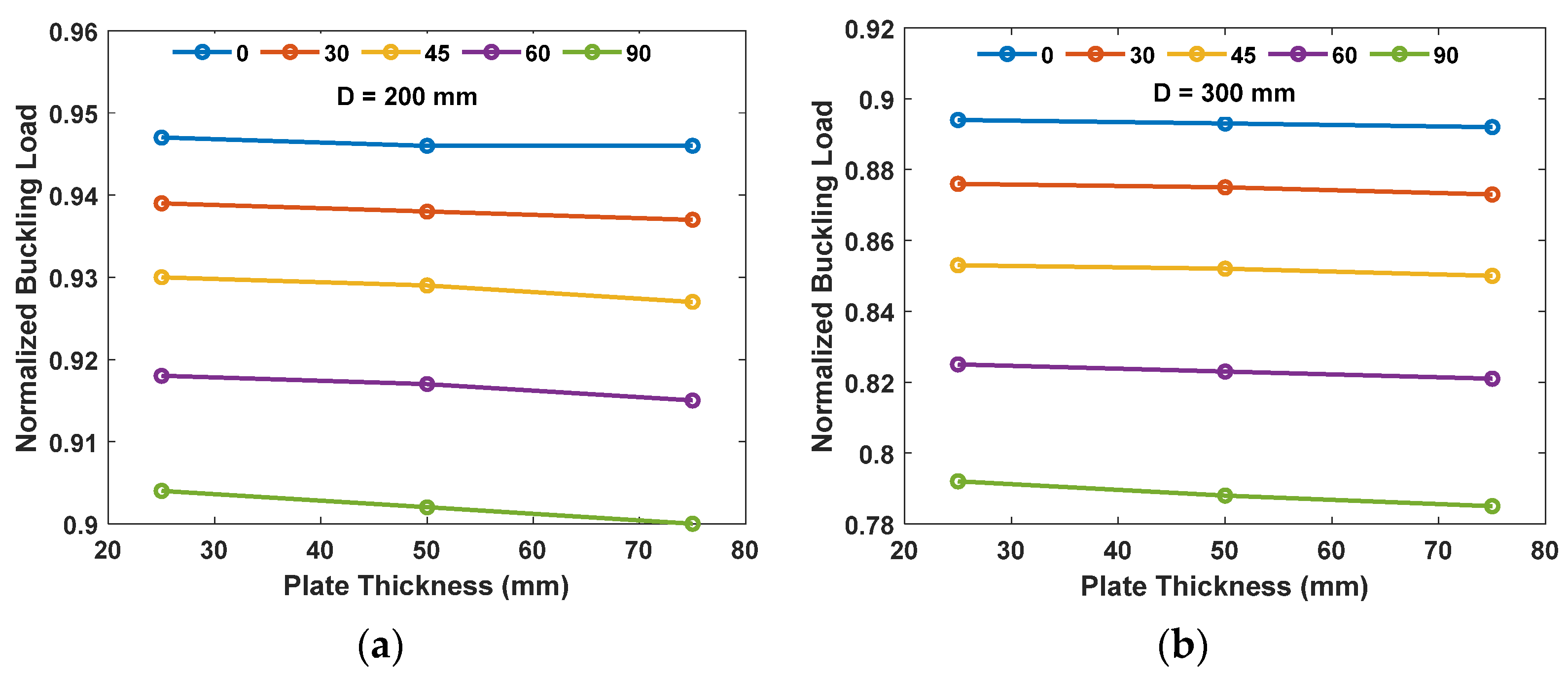
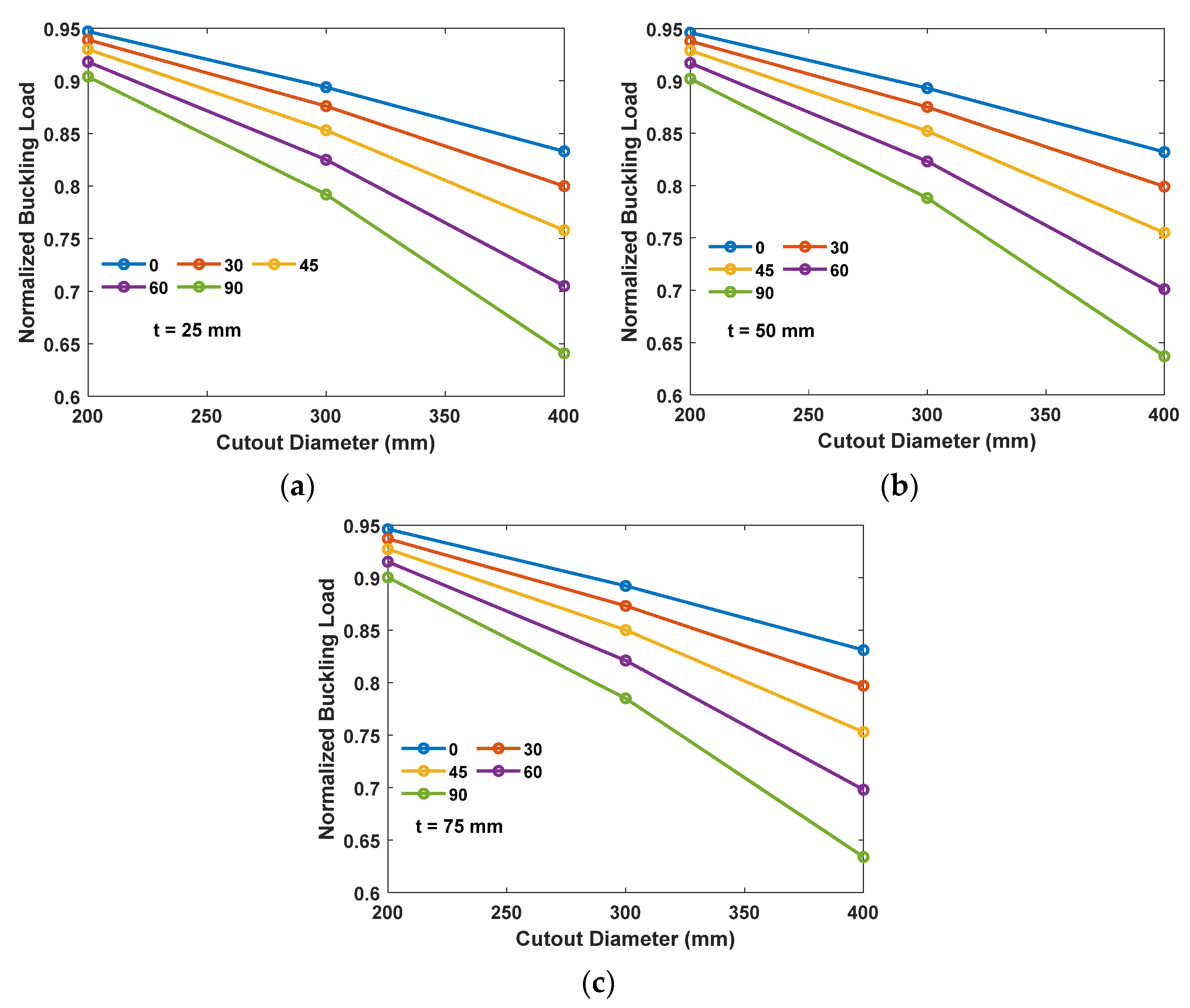
  • The increase in the plate thickness and decrease in the circular cutout diameter increases the critical buckling load of the FGM thin plate.
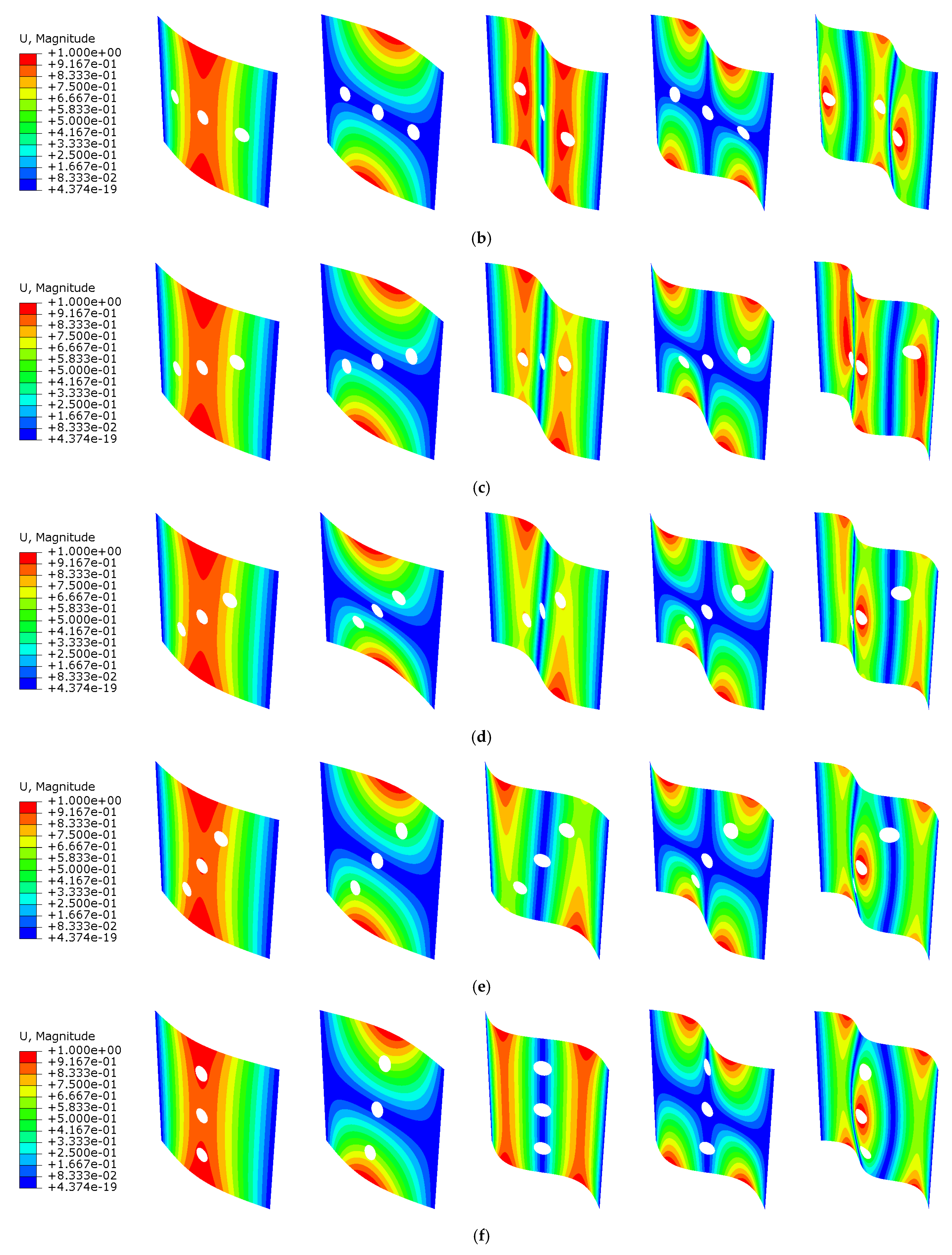
  • Horizontal arrangements exhibit the highest critical buckling load and best buckling performance. As the arrangement shifts to a vertical one, the critical buckling value decreases.
  • The normalized buckling load decreases as the plate thickness and cutout size increase. The change in the normalized buckling load is more apparent as the cutout arrangements approach a vertical position.
  • Generally, FGM plates with a horizontal circular cutout arrangement, a smaller cutout diameter, and a larger thickness provide the highest critical buckling load.
Future work should focus on post-buckling analysis to gain a deeper understanding of the failure phenomenon of FGM plates in general, and plates with multiple cutouts in particular. Although FEA provides an accurate depiction of the buckling behavior, aided with visual representation, an experimental analysis is still required to validate the calculations and methodology used in the analysis.

Author Contributions

Conceptualization, M.E. and A.A.; methodology, M.E. and A.A.; software, M.E. and A.A.; validation, M.E. and A.A.; formal analysis, M.E. and A.A.; investigation, M.E. and A.A.; resources, M.E., A.A., and R.H.; data curation, M.E. and A.A.; writing—original draft preparation, M.E. and A.A.; writing—review and editing, M.E., A.A., R.H., and M.A.; visualization, M.E. and A.A.; supervision, R.H. and M.A.; project administration, R.H. and M.A.; funding acquisition, R.H. All authors have read and agreed to the published version of the manuscript.

Funding

This research received no external funding.

Institutional Review Board Statement

Not applicable.

Informed Consent Statement

Not applicable.

Data Availability Statement

Not applicable.

Conflicts of Interest

The authors declare no conflict of interest.

References

  1. Zhao, H.; Cheng, Y.; Lv, H.; Ji, G.; Du, Y. A novel hierarchically porous magnetic carbon derived from biomass for strong lightweight microwave absorption. Carbon 2018, 142, 245–253. [Google Scholar] [CrossRef]
  2. Sun, X.; He, M.; Li, Z. Novel engineered wood and bamboo composites for structural applications: State-of-art of manufacturing technology and mechanical performance evaluation. Constr. Build. Mater. 2020, 249, 118751. [Google Scholar] [CrossRef]
  3. Akhtar, A.; Sarmah, A.K. Novel biochar-concrete composites: Manufacturing, characterization and evaluation of the mechanical properties. Sci. Total Environ. 2018, 616–617, 408–416. [Google Scholar] [CrossRef] [PubMed]
  4. Zhu, W.; Lei, J.; Zhang, Z.; Sun, Q.; Chen, W.; Xiao, L.; Sun, J. Microstructural dependence of strength and ductility in a novel high strength β titanium alloy with Bi-modal structure. Mater. Sci. Eng. A 2019, 762, 138086. [Google Scholar] [CrossRef]
  5. Zhang, J.; Lu, G.; You, Z. Large deformation and energy absorption of additively manufactured auxetic materials and structures: A review. Compos. Part B Eng. 2020, 201, 108340. [Google Scholar] [CrossRef]
  6. Ali, A.; Andriyana, A. Properties of multifunctional composite materials based on nanomaterials: A review. RSC Adv. 2020, 10, 16390–16403. [Google Scholar] [CrossRef] [PubMed]
  7. Li, T.; Liu, F.; Wang, L. Enhancing indentation and impact resistance in auxetic composite materials. Compos. Part B Eng. 2020, 198, 108229. [Google Scholar] [CrossRef]
  8. Alashkar, A.; Alami, A.H. Energy Harvesting Materials: Overview of Thermoelectrical Material. Ref. Modul. Mater. Sci. 2021, 4, 319–325. [Google Scholar]
  9. Saleh, B.; Jiang, J.; Fathi, R.; Al-Hababi, T.; Xu, Q.; Wang, L.; Song, D.; Ma, A. 30 Years of functionally graded materials: An overview of manufacturing methods, Applications and Future Challenges. Compos. Part B Eng. 2020, 201, 108376. [Google Scholar] [CrossRef]
  10. El-Galy, I.M.; Saleh, B.I.; Ahmed, M.H. Functionally graded materials classifications and development trends from industrial point of view. SN Appl. Sci. 2019, 1, 1378. [Google Scholar] [CrossRef]
  11. Zhang, N.; Khan, T.; Guo, H.; Shi, S.; Zhong, W.; Zhang, W. Functionally Graded Materials: An Overview of Stability, Buckling, and Free Vibration Analysis. Adv. Mater. Sci. Eng. 2019, 2019, 1354150. [Google Scholar] [CrossRef] [Green Version]
  12. Li, Y.; Feng, Z.; Hao, L.; Huang, L.; Xin, C.; Wang, Y.; Bilotti, E.; Essa, K.; Zhang, H.; Li, Z.; et al. A Review on Functionally Graded Materials and Structures via Additive Manufacturing: From Multi-Scale Design to Versatile Functional Properties. Adv. Mater. Technol. 2020, 5, 1900981. [Google Scholar] [CrossRef]
  13. Hosseini, S.M.H.; Arvin, H. Thermo-rotational buckling and post-buckling analyses of rotating functionally graded microbeams. Int. J. Mech. Mater. Des. 2020, 17, 55–72. [Google Scholar] [CrossRef]
  14. Zhang, P.; Qing, H. Buckling analysis of curved sandwich microbeams made of functionally graded materials via the stress-driven nonlocal integral model. Mech. Adv. Mater. Struct. 2020, 29, 1211–1228. [Google Scholar] [CrossRef]
  15. Ziou, H.; Guenfoud, H.; Guenfoud, M. Buckling analysis behavior of functionally graded beams. Jordan J. Civ. Eng. 2020, 14, 347–358. [Google Scholar]
  16. Daikh, A.A.; Guerroudj, M.; El Adjrami, M.; Megueni, A. Thermal Buckling of Functionally Graded Sandwich Beams. Adv. Mater. Res. 2019, 1156, 43–59. [Google Scholar] [CrossRef]
  17. Wu, W.-Q.; Xu, Y.-F.; Rao, H.-S.; Su, C.-Y.; Kuang, D.-B. Trilayered Photoanode of TiO2 Nanoparticles on a 1D–3D Nanostructured TiO2-Grown Flexible Ti Substrate for High-Efficiency (9.1%) Dye-Sensitized Solar Cells with Unprecedentedly High Photocurrent Density. J. Phys. Chem. C 2014, 118, 16426–16432. [Google Scholar] [CrossRef]
  18. Belkhodja, Y.; Ouinas, D.; Zaoui, F.Z.; Fekirini, H. An exponential-trigonometric higher order shear deformation theory (HSDT) for bending, free vibration, and buckling analysis of functionally graded materials (FGMs) plates. Adv. Compos. Lett. 2020, 29, 1–19. [Google Scholar] [CrossRef]
  19. Zenkour, A.M.; Aljadani, M.H. Buckling analysis of actuated functionally graded piezoelectric plates via a quasi-3D refined theory. Mech. Mater. 2020, 151, 103632. [Google Scholar] [CrossRef]
  20. Njim, E.K.; Al-Waily, M.; Bakhy, S.H. A Critical Review of Recent Research of Free Vibration and Stability of Functionally Graded Materials of Sandwich Plate. IOP Conf. Ser. Mater. Sci. Eng. 2021, 1094, 012081. [Google Scholar] [CrossRef]
  21. Fiorini, A.; Ruta, G. Buckling of circular plates with functional grading in two directions. Meccanica 2021, 56, 245–252. [Google Scholar] [CrossRef]
  22. Van Vinh, P.; Van Chinh, N.; Tounsi, A. Static bending and buckling analysis of bi-directional functionally graded porous plates using an improved first-order shear deformation theory and FEM. Eur. J. Mech. A/Solids 2022, 96, 104743. [Google Scholar] [CrossRef]
  23. Ali, E.Y.; Bayleyegn, Y.S. Analytical and numerical buckling analysis of rectangular functionally-graded plates under uniaxial compression. In Proceedings of the Annual Stability Conference Structural Stability Research Council, St. Louis, MO, USA, 2–5 April 2019; Volume 2, pp. 534–547. [Google Scholar]
  24. Cuong-Le, T.; Nguyen, K.D.; Nguyen-Trong, N.; Khatir, S.; Nguyen-Xuan, H.; Abdel-Wahab, M. A three-dimensional solution for free vibration and buckling of annular plate, conical, cylinder and cylindrical shell of FG porous-cellular materials using IGA. Compos. Struct. 2020, 259, 113216. [Google Scholar] [CrossRef]
  25. Khatir, S.; Tiachacht, S.; Le Thanh, C.; Ghandourah, E.; Mirjalili, S.; Wahab, M.A. An improved Artificial Neural Network using Arithmetic Optimization Algorithm for damage assessment in FGM composite plates. Compos. Struct. 2021, 273, 114287. [Google Scholar] [CrossRef]
  26. Le Thanh, C.; Nguyen, T.N.; Vu, T.H.; Khatir, S.; Wahab, M.A. A geometrically nonlinear size-dependent hypothesis for porous functionally graded micro-plate. Eng. Comput. 2020, 38, 449–460. [Google Scholar] [CrossRef]
  27. Li, D.M.; Featherston, C.A.; Wu, Z. An element-free study of variable stiffness composite plates with cutouts for enhanced buckling and post-buckling performance. Comput. Methods Appl. Mech. Eng. 2020, 371, 113314. [Google Scholar] [CrossRef]
  28. Evran, S.; Yildir, S.Z. Eigenvalue Buckling Analysis of Beams with Different Width and Square Cutout. Aksaray Univ. J. Sci. Eng. 2022, 6, 71–78. [Google Scholar] [CrossRef]
  29. Bash, A.M.; Mnawe, S.E.; Salah, S.A. Numerical buckling analysis of carbon fibre-epoxy composite plates with different cutouts number by finite element method. AIMS Mater. Sci. 2020, 7, 46–59. [Google Scholar] [CrossRef]
  30. Akbar, R.M.; Suryoatmono, B. Numerical study of inelastic buckling behavior of rectangular steel plates with circular openings under shear forces. MATEC Web Conf. 2019, 258, 05026. [Google Scholar] [CrossRef]
  31. Yanli, G.; Xiaoqing, S.; Xiao, L.; Xingyou, Y.; Zhifan, X.; Bin, X.; Jianyi, S. Elastic buckling of thin plate with circular holes in bending. E3S Web Conf. 2019, 136, 04043. [Google Scholar] [CrossRef]
  32. Wang, G.; Sun, H.; Peng, H.; Uemori, R. Buckling and ultimate strength of plates with openings. Ships Offshore Struct. 2009, 4, 43–53. [Google Scholar] [CrossRef]
  33. Kumar, R.; Lal, A.; Sutaria, B. Comparative buckling analysis of laminated composite plates with various shapes of hole. Mater. Today Proc. 2020, 44, 4009–4012. [Google Scholar] [CrossRef]
  34. Ansari, R.; Hassani, R.; Torabi, J. Mixed-type formulation of higher-order shear deformation theory for vibration and buckling analysis of FG-GPLRC plates using VDQFEM. Compos. Struct. 2019, 235, 111738. [Google Scholar] [CrossRef]
  35. Erdem, S.; Kaman, M.O.; Gur, M. Post-buckling behavior of carbon fiber epoxy composite plates. J. Mech. Sci. Technol. 2019, 33, 1723–1730. [Google Scholar] [CrossRef]
  36. Vivek, K.; Babu, T.S.; Ram, K.S. Buckling analysis of functionally graded thin square plates with triangular cut-out subjected to uni-axial loads. Mater. Today: Proc. 2020, 24, 662–672. [Google Scholar] [CrossRef]
  37. Elkafrawy, M.; Alashkar, A.; Hawileh, R.; AlHamaydeh, M. FEA Investigation of Elastic Buckling for Functionally Graded Material (FGM) Thin Plates with Different Hole Shapes under Uniaxial Loading. Buildings 2022, 12, 802. [Google Scholar] [CrossRef]
  38. Zhang, J.; Yu, T.; Bui, T.Q. Composite FG plates with different internal cutouts: Adaptive IGA buckling analysis without trimmed surfaces. Compos. Struct. 2020, 259, 113392. [Google Scholar] [CrossRef]
Figure 1. The variation of the power index on the young’s modulus of elasticity.
Jcs 06 00277 g001
Figure 2. (a) The schematic of the FGM plate; (b) Meshing details.
Jcs 06 00277 g002
Figure 3. The variation of the cutout arrangements on the normalized buckling load for (a) D = 200 mm, (b) D = 300 mm, and (c) D = 400 mm with various plate thickness.
Jcs 06 00277 g003aJcs 06 00277 g003b
Figure 4. The variation of the cutout arrangements on the normalized buckling load for (a) t = 25 mm, (b) t = 50 mm, and (c) t = 75 mm with various plate thickness.
Jcs 06 00277 g004
Figure 5. Von Mises stress of FGM plates with (a) a plate thickness of 50 mm, a cutout diameter of 200 mm with an arrangement of (b) 0 ° , (c) 30 ° , (d) 45 ° , (e) 60 ° , and (f) 90 ° .
Jcs 06 00277 g005
Figure 6. Von Mises stress of FGM plates with (a) a plate thickness of 50 mm, a cutout diameter of 300 mm with an arrangement of (b) 0 ° , (c) 30 ° , (d) 45 ° , (e) 60 ° , and (f) 90 ° .
Jcs 06 00277 g006
Figure 7. Von Mises stress of FGM plates with (a) a plate thickness of 50 mm, a cutout diameter of 400 mm with an arrangement of (b) 0 ° , (c) 30 ° , (d) 45 ° , (e) 60 ° , and (f) 90 ° .
Jcs 06 00277 g007
Figure 8. The first five buckling modes of FGM plates with (a) a plate thickness of 25 mm, a cutout diameter of 200 mm, and an arrangement of (b) 0 ° , (c) 30 ° , (d) 45 ° , (e) 60 ° , and (f) 90 ° .
Jcs 06 00277 g008aJcs 06 00277 g008b
Figure 9. The first five buckling modes of FGM plates with (a) a plate thickness of 25 mm, a cutout diameter of 300 mm, and an arrangement of (b) 0 ° , (c) 30 ° , (d) 45 ° , (e) 60 ° , and (f) 90 ° .
Jcs 06 00277 g009aJcs 06 00277 g009b
Figure 10. The first five buckling modes of FGM plates with (a) a plate thickness of 25 mm, a cutout diameter of 400 mm, and an arrangement of (b) 0 ° , (c) 30 ° , (d) 45 ° , (e) 60 ° , and (f) 90 ° .
Jcs 06 00277 g010aJcs 06 00277 g010b
Table 1. Input parameters for the numerical simulation.
ParameterSymbolValueUnit
Plate Width b 2000mm
Plate Height a 2000mm
Plate Thickness t 25, 50, 75mm
Cutout Diameter D 200, 300, 400mm
Cutout Distance S 600mm
Arrangement Angle θ 0, 30, 45, 60, 90 D e g   °
Position of Material z 0-
Power Index p 1-
Volume Fraction f 0.5-
Young Modulus of Ceramic E c 380 GPa
Young Modulus of Metal E m 203 GPa
Young Modulus of FGM E 292 GPa
Poisson’s Ratio v 0.3-
Element Type-Shell S4R-
Mesh Size- 20 × 20mm2
Table 2. The critical buckling load of the FGM plate with various cutout arrangements, plate thickness, and cutout size.
Thickness (mm)Diameter (mm) Angle   ( ° ) Buckling Load (kN)
25--1972
200 01868
301852
451833
601810
901783
300 01762
301727
451683
601627
901561
40001642
301578
451494
601390
901265
50--15,737
014,894
3014,768
2004514,612
6014,423
9014,198
014,045
3013,765
3004513,401
6012,950
9012,408
013,093
3012,568
4004511,885
6011,037
9010,030
75--52,950
050,074
3049,638
2004549,104
6048,450
9047,668
047,208
3046,244
3004544,996
6043,450
9041,592
044,012
3042,190
4004539,846
6036,962
9033,556
Publisher’s Note: MDPI stays neutral with regard to jurisdictional claims in published maps and institutional affiliations.

