Article

Finite Element Simulation of FRP-Strengthened Thin RC Slabs

Civil Engineering Department, American University of Sharjah, Sharjah P.O. Box 26666, United Arab Emirates
*
Author to whom correspondence should be addressed.
J. Compos. Sci. 2022, 6(9), 263; https://doi.org/10.3390/jcs6090263
Submission received: 1 August 2022 / Revised: 30 August 2022 / Accepted: 6 September 2022 / Published: 8 September 2022
(This article belongs to the Special Issue Characterization and Modelling of Composites, Volume III)

Abstract

:
This study aims to investigate the flexural behavior of high-strength thin slabs externally strengthened with fiber-reinforced polymer (FRP) laminates through a numerical simulation. A three-dimensional (3D) finite element (FE) model is created to simulate the response of strengthened reinforced concrete (RC) slabs under a four-point bending test. The numerical model results in terms of load-deflection behavior, and ultimate loads are verified using previously published experimental data in the literature. The numerical results show a good agreement with the experimental results. The FE model is then employed in a parametric study to inspect the effect of concrete compressive strength on the performance of RC thin slabs strengthened with different FRP types, namely carbon fiber-reinforced polymers (CFRP), polyethylene terephthalate fiber-reinforced polymers (PET-FRP), basalt fiber-reinforced polymers (BFRP) and glass fiber-reinforced polymers (GFRP). The results showed that the highest strength enhancement was obtained by the slab that was strengthened by CFRP sheets. Slabs that were strengthened with other types of FRP sheets showed an almost similar flexural capacity. The effect of concrete compressive strength on the flexural behavior of the strengthened slabs was moderate, with the highest effect being a 15% increase in the ultimate load between two consecutive values of compressive strength, occurring in the CFRP-strengthened slabs. It can thus be concluded that the developed FE model could be used as a platform to predict the behavior of reinforced concrete slabs when strengthened with different types of FRP composites. It can also be concluded that the modulus of elasticity of the composite plays a major role in determining the flexural capacity of the strengthened slabs.
Keywords:
FRP; slabs; flexural; RC; FE

1. Introduction

Reinforced concrete (RC) buildings are susceptible to deterioration. This is not only due to potential hazards such as earthquakes and fire loads, but also due to a lack of maintenance, design errors, dynamic changes including overload and changes in the structure’s functions. The repairing and retrofitting of RC structures using fiber-reinforced polymers (FRP) has been known as an outstanding retrofitting technology [1,2,3,4], thanks to its superior properties of high strength, resistance to corrosion and ease of use. One of the important components of the reinforced concrete structure is the slab. The strengthening of RC members using FRP composites has been extensively studied and implemented in the last few decades [5,6,7,8]. This technology allowed for significant strength and durability enhancement in addition to the advantage of a quick installation with minimum service disruption. The use of high-strength concrete members has emerged from the need to construct high-rise buildings and has allowed for the design of smaller sections, resulting in a reduction of the overall structure’s weight. Using thin slabs also provides an aesthetic appearance in terms of a taller floor-to-ceiling height. Therefore, high-strength flat solid slabs can be found in almost all modern medium- and high-rise RC structures. Although a minimum thickness is specified for RC slabs in the ACI-318 code provisions to prevent deflections [9], it is permitted for the designer to use thinner slabs when short- and long-term deflection calculations are performed and shown to have no adverse effect on the behavior of the slab.
Few studies have been conducted on the performance of FRP-strengthened slabs in the literature [10,11,12,13,14]. A recent study by Mahmoud et al. [10] reported the results of a two-point loading test on 18 CFRP-strengthened RC slabs with a thickness of 100 mm and a concrete compressive strength of 70 MPa. The reinforcement ratio and the number of CFRP layers varied among the specimens. The increase in flexural capacity ranged from 65% to 350%. The highest percentage was obtained for the specimens having a high reinforcement ratio and two CFRP layers. However, these specimens exhibited the least ductility.
Numerical simulation is a powerful tool that helps in deepening the understanding of engineering problems and the optimization of the design processes. Studying the behavior of RC structures and structural members through finite element methods saves considerable time and resources and allows for testing many variables and materials. Many numerical investigations have been carried out to study the flexural behavior of FRP-strengthened RC beams and slabs [7,15,16,17,18,19,20]. However, to the best of the author’s knowledge, no numerical studies have been conducted to investigate the flexural behavior of strengthened thin and high-strength RC slabs with FRP laminates. Moreover, most previous studies focused on CFRP as the strengthening material, while others studied other conventional FRP composites such as glass fiber-reinforced polymers (GFRP) and aramid fiber-reinforced polymers (AFRP). However, it is important to investigate other types of available and less-used FRP composites to compare their behavior, efficiency and feasibility. For example, polyethylene terephthalate (PET-FRP) is a newly developed bilinear sustainable material, manufactured using recycled plastics. Another eco-friendly material is the inorganic basalt fiber-reinforced polymer (BFRP). These two materials demonstrated good mechanical properties and promising flexural behavior results in terms of ductility. Therefore, studying the behavior of thin slabs strengthened with different types of FRP composites in combination with varied concrete compressive strengths through a finite element investigation will provide useful information that will bridge the gap in the literature regarding the feasibility of using various FRP types with a higher concrete compressive strength.
The purpose of this study is to model high-strength thin reinforced concrete slabs externally bonded with CFRP laminates through a non-linear finite element model developed using the commercial software ANSYS [21]. After validating the model’s accuracy by comparing the numerical results with experimentally reported load-deflection curves for the specimens in a previous experimental test published in the literature, the model is utilized to inspect different types of FRP materials, namely, CFRP, GFRP, PET-FRP and BFRP. The concrete compressive strength was varied for each FRP type to assess the extent of the concrete strength’s effect on the behavior of FRP-strengthened thin slabs. In this regard, non-linear material properties of concrete and steel reinforcement were incorporated into the FE model. Moreover, the interfacial behavior between the concrete surface and the FRP laminate was simulated to capture the possible mode of failure of the strengthened specimens, which was the separation of the laminate from the concrete surface (debonding).

2. Materials and Methods

2.1. Summary of Experimental Program

The numerical model was developed to simulate the behavior of three high-strength reinforced concrete (RC) slabs strengthened with unidirectional CFRP laminates and previously tested by Mahmoud et al. [10] under a four-point bending test (see Figure 1). The tested slabs were 100 × 300 × 2000 mm. CFRP sheets with a 100 mm width were externally bonded to the slab’s soffit (the CFRP sheet partially covered the slab’s bottom width). The slabs were divided into three groups. The steel reinforcement ratio was varied among the groups as follows: low, moderate and high. The dimensions, test setup and detailing of a typical slab are shown in Figure 1. A control slab and two slabs strengthened with 1 and 2 layers of CFRP laminates were chosen for validation from the low reinforcement ratio group. The flexural reinforcement consisted of 2Ø8 mm.

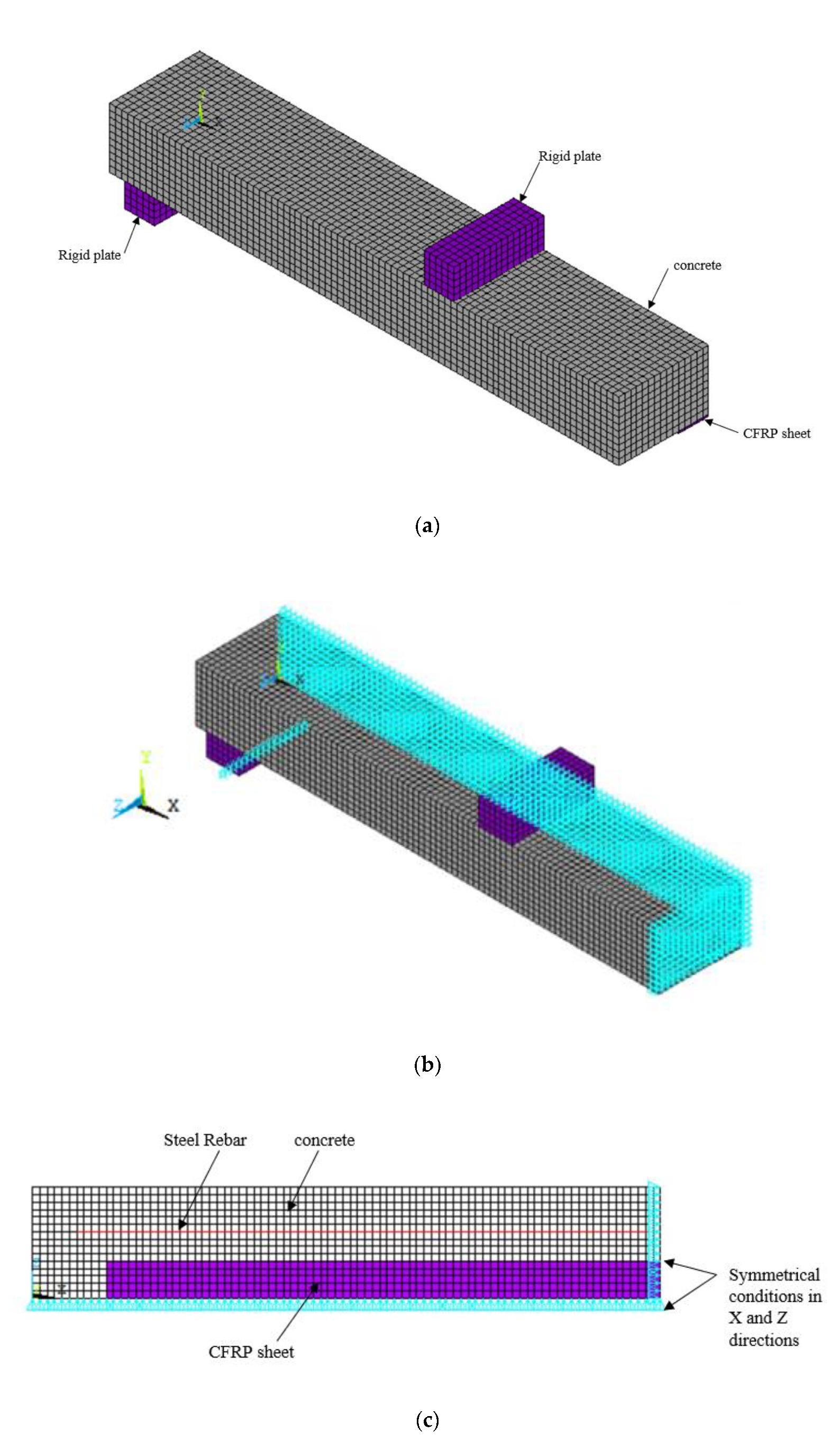
2.2. Numerical Model Description

A three-dimensional FE numerical model is developed using ANSYS [21]. Figure 2 shows the FE model’s components of the slab in the software. In nonlinear analyses, it is important to utilize all possible simplifications in order to improve convergence and reduce the computational cost. For instance, different mesh densities were examined for the control specimen to obtain the optimum mesh size that provided accurate results with a reasonable computational time. Moreover, a quarter of the slab was modeled since symmetry exists in the X- and Z-directions (Half of the length and width of the slab specimen was created).
Roller supports were assigned to the nodes in these directions, as can be observed in Figure 2b. This approach was followed since it saves considerable computational time during the non-linear analysis. For this type of analysis, ANSYS uses the Newton-Raphson method, which involves an iterative procedure with three distinct levels: load steps, substeps and equilibrium iterations. Displacement-controlled loading is adapted in this problem where the number of load steps, the displacement at each step and the number of substeps for each load increment are specified and entered using an ANSYS subroutine.

2.3. Element Types

The finite element methods subdivide large systems into smaller and simpler parts (finite elements). For each component of the structural member, a different element type is assigned according to the ANSYS library [21]. Concrete was modeled using the SOLID65 element to capture concrete cracking and crushing [22]. Rigid plates and FRP sheets were assigned a SOLID185 element type. These two elements are 8-noded linear brick elements. Steel reinforcement is simulated using the LINK180 element, which is a 2-noded linear truss element. More information on the theory and mechanics of the mentioned elements can be found in the ANSYS theory reference [22]. To model the interfacial behavior between concrete and the FRP sheet, epoxy was represented using INTER205 elements that transfer stresses between two different components. The mechanism follows the cohesive zone material model where maximum shear stress, its corresponding slip and the maximum slip are specified in the model. These three values are usually calculated using existing bond-slip models in the literature. A typical bond-slip model is characterized by an ascending curve up to the maximum bond stress. After that, the curve descends until the maximum slip occurs between the two adhered materials, as shown in Figure 3. In this study, Nakaba et al.’s [23] bond-slip model presented in Equations (1) and (2) was adapted to simulate the debonding phenomena of the FRP sheet from the concrete substrate.
τ = τ max s s 0 3 / 2 + s s 0 3
τ m a x = 3.5 f c 0.19
where τ m a x and f c are the maximum bond stress and the concrete compressive strength in MPa, respectively. According to Nakaba et al. [23], the corresponding slip ( s 0 ) has a constant value of 0.065 mm. The maximum value of the slip is four times s 0 , which equals 0.26 mm. Using Equation (2), the value of the maximum bond stress equals 7.85 MPa, as presented in Figure 3.

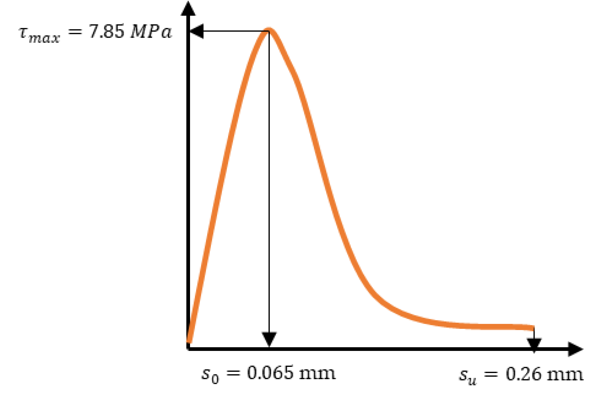
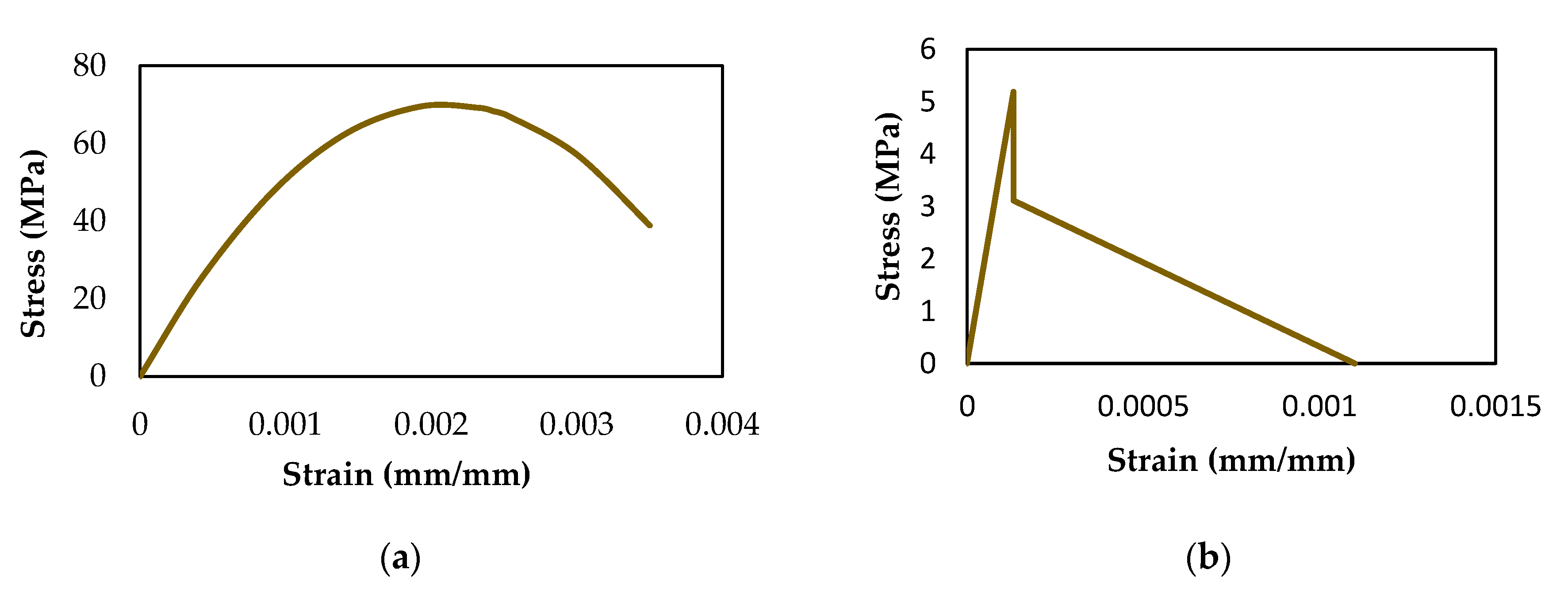
2.4. Material Models

Constitutive laws of each material comprising the slab were incorporated into the model. Following the experimental test data in [10], the concrete compressive strength (f′c) was 70 MPa. The modulus of elasticity is taken as 4700√f′c, where f′c is the concrete compressive strength in MPa. Substituting 70 MPa for f′c gives an elastic modulus of 39 GPa. Poisson’s ratio for concrete is taken as 0.2. The non-linear compressive stress-strain curve was calculated using Hognestad et al.’s formula [24] and is shown in Figure 4a. The tensile stress-strain behavior of concrete was simulated using a trilinear curve, as suggested by William and Warnke’s model [24], and is illustrated in Figure 4b where the maximum value of tensile stress is taken as 0.62√f′c. Additionally, the open and close shear crack coefficients were assigned as 0.3 and 0.5, respectively. The tensile yield strength of the steel reinforcement was 550 MPa, and the non-linear behavior of steel was modeled as elastic-perfectly plastic. Young’s modulus of elasticity was input as 200 GPa and Poisson’s ratio as 0.3.
In general, FRP composites possess a linear elastic behavior until rupture under ultimate loads. In this case, only the modulus of elasticity and Poisson’s ratio are assigned in the model. FRP materials have different properties in each direction. Therefore, orthotropic material properties were assigned in the model. For the CFRP-strengthened slab (the model to be validated), the orthotropic material properties of the CFRP laminate are taken from reference paper [10] as: Ex = 73 GPa, Ey = Ez = 4.6 GPa, where Ex, Ey and Ez are the moduli of elasticity of CFRP in the x, y and z directions, respectively. Poisson’s ratio in the xy plane (vxy) is taken as 0.3, while Poisson’s ratio in the xz and yz planes (vxz, vyz) are 0.4. Finally, the shear moduli (G) in the xy, xz, planes are assigned as 1.7 GPa, while the shear modulus in the yz plane is taken as 1.6 GPa. The properties for the other investigated FRPs are taken from previous studies [5,25,26] and explained in more depth in the following sections.

3. Results and Discussion

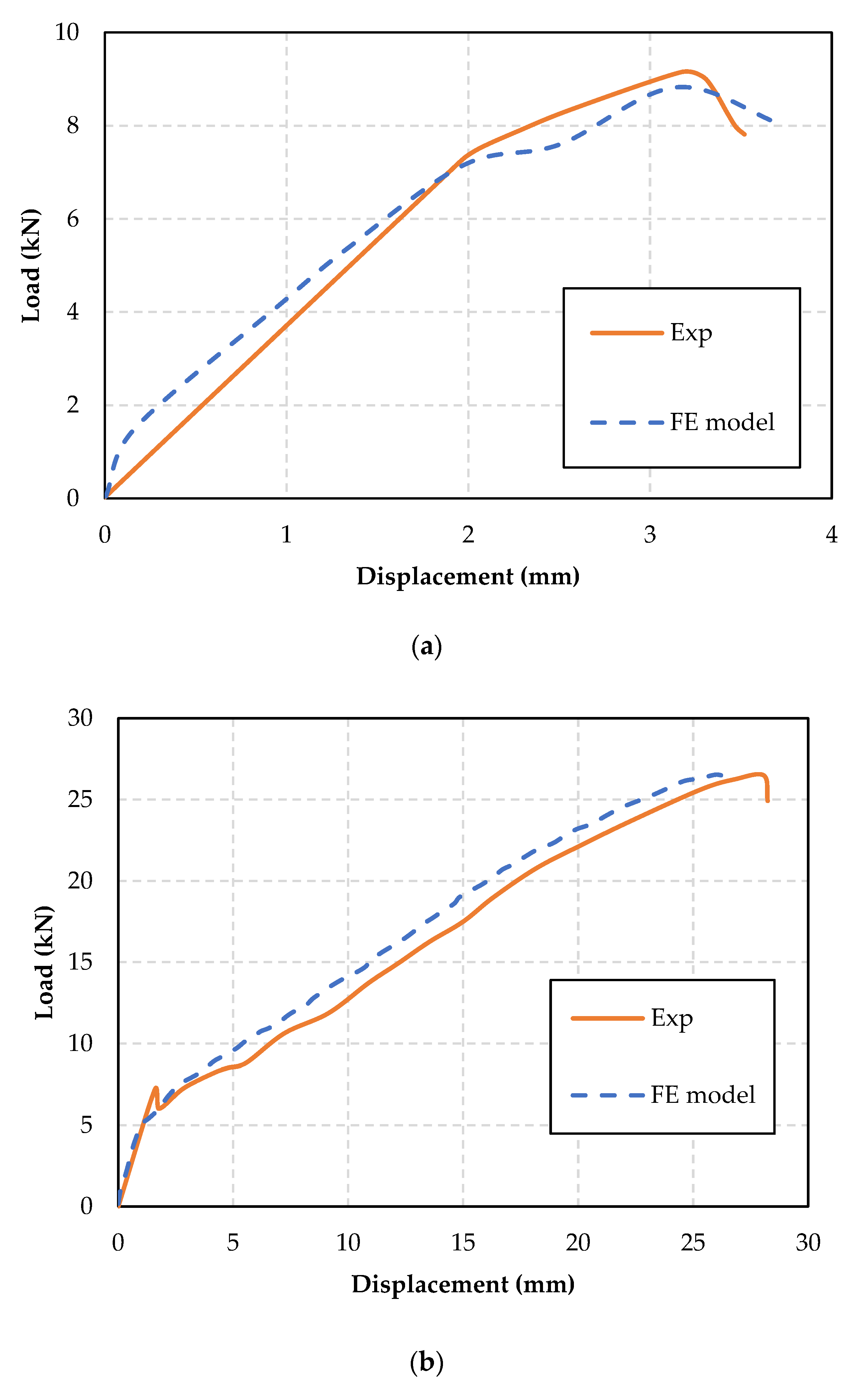
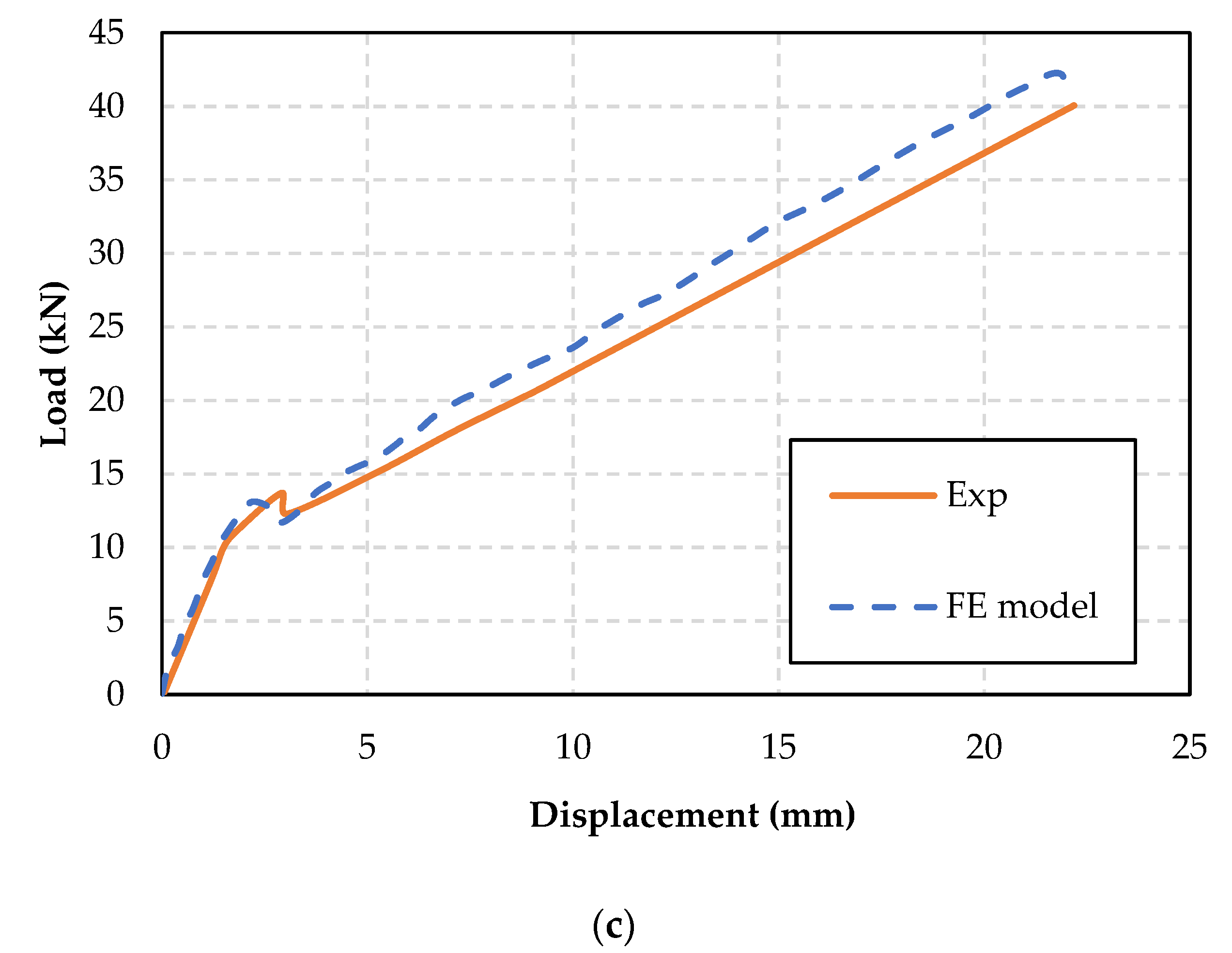
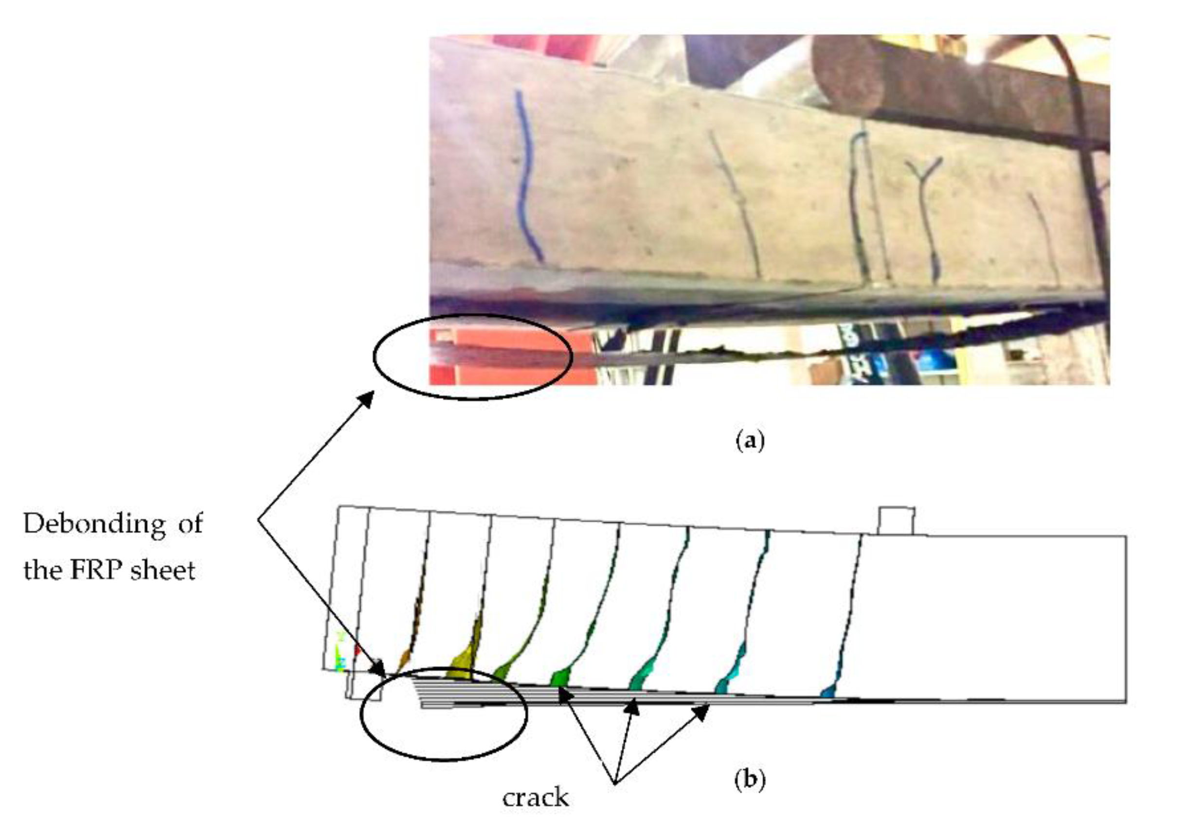
3.1. FE Model Validation

The validity of the generated FE model was checked by comparing the load-deflection curves obtained from the model with the experimental load-deflection curves presented in [10]. Figure 5 shows the load-versus-midspan deflection curves for the control slab and the CFRP-strengthened slab with one (C1) and two layers (C2) from the numerical model and the experimental test [10]. It is observed that there is a good agreement between the FE model results and the experimental results. Table 1 shows the maximum numerical and experimental ultimate loads and deflections for the considered specimens along with the quantified percentage errors. Slight differences can be observed between the numerical and experimental curves after steel reinforcement yielding, which can be attributed to the slight variations in the materials’ behavior, especially the steel reinforcement, assumed to have a bilinear stress-strain curve (elastic-fully plastic). The maximum percentage difference in the ultimate load was reported for the control slab, equaling 3.5%. In terms of deflection, the maximum percentage difference in the ultimate deflection was 12%, corresponding to the control slab. This verifies the accuracy of the developed FE models, and it can therefore be further utilized to carry out a parametric study to investigate other parameters, namely the FRP type and concrete compressive strength.

3.2. Failure Criteria

Failure of the externally bonded reinforced concrete slabs occurs when one or more of the following conditions develop: yielding of steel reinforcement, concrete crushing, FRP debonding or FRP rupture. The typical failure mode of strengthened flexural members reported in most previous studies is FRP debonding after steel yielding [27,28]. This type of failure was initiated in the two FE models of the validated slabs, which matches the failure mode reported in the experimental study [10]. Since the concrete compressive strength was relatively high, concrete crushing did not occur in any of the modeled specimens. Therefore, the concrete crushing option was deactivated in the SOLID65 element for the following models in the parametric analysis. Figure 6 shows the debonding failure of the strengthened slab with one CFRP layer, as reported in the experimental study and obtained in the FE analysis. It can be observed from the figure that there is a close match in the failure mode between the experimental and numerical results. Debonding of the FRP sheet from the concrete substrate can be clearly seen in the two pictures. Concrete cracks have also developed in the numerical model, as shown in Figure 6b.

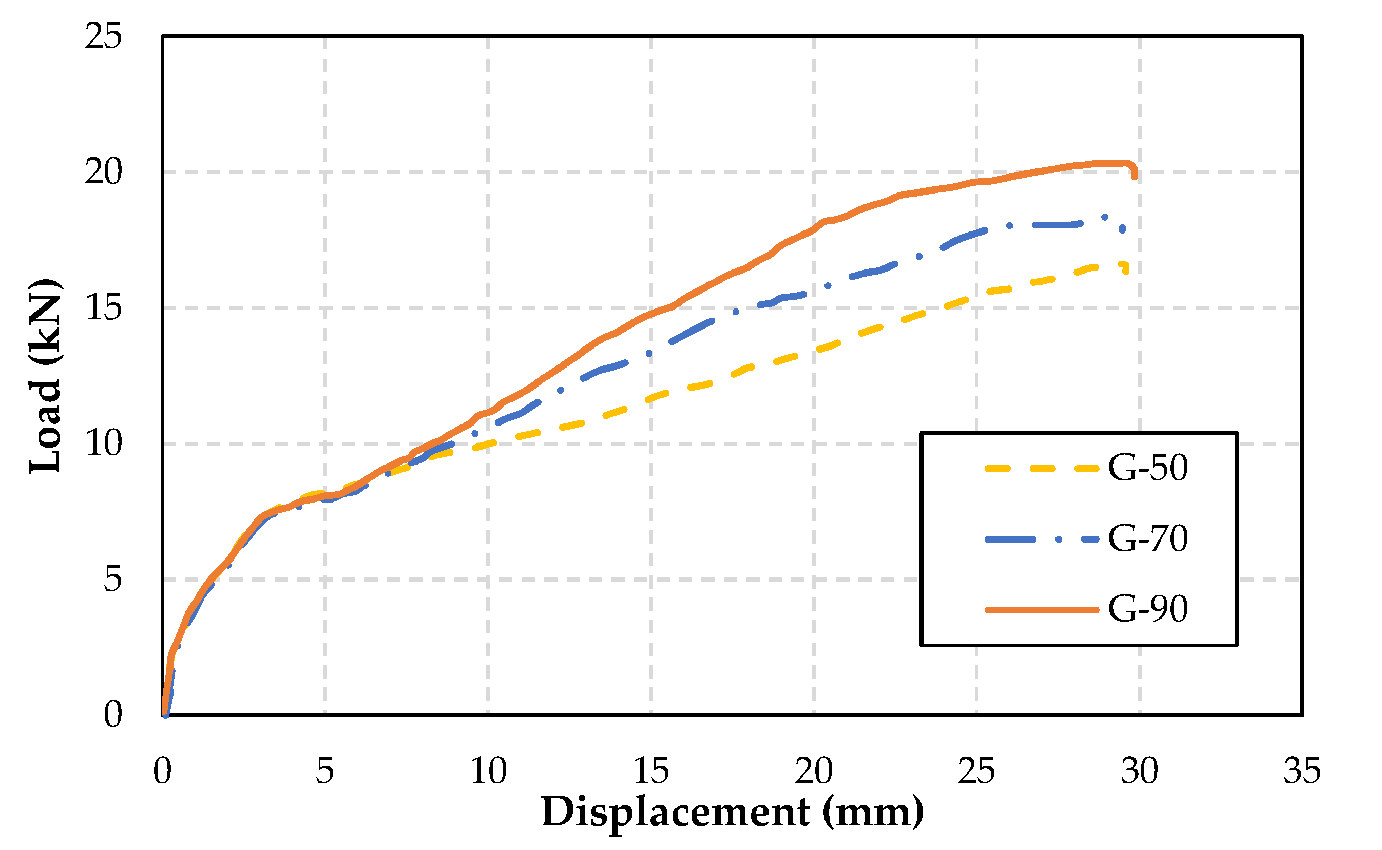
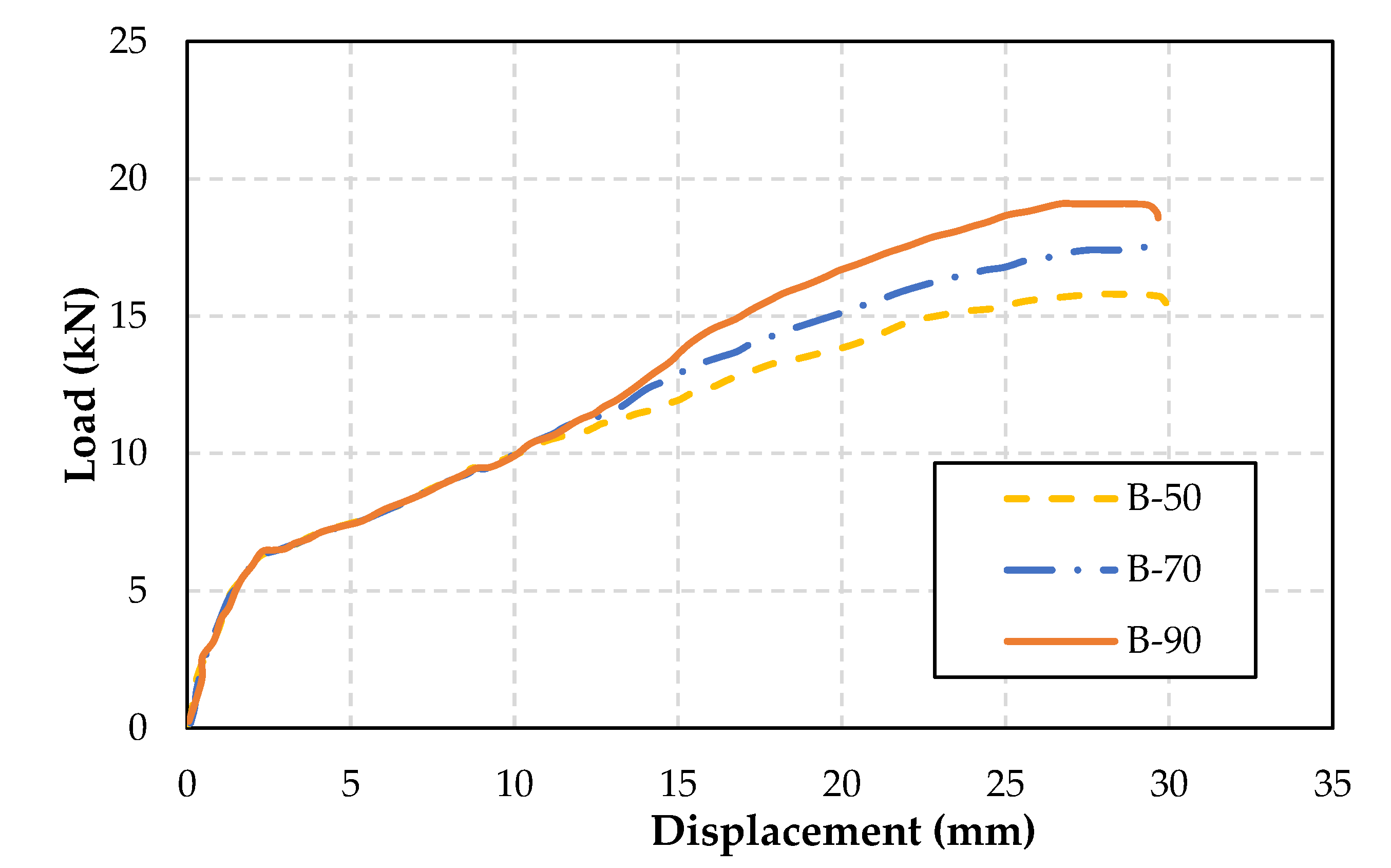
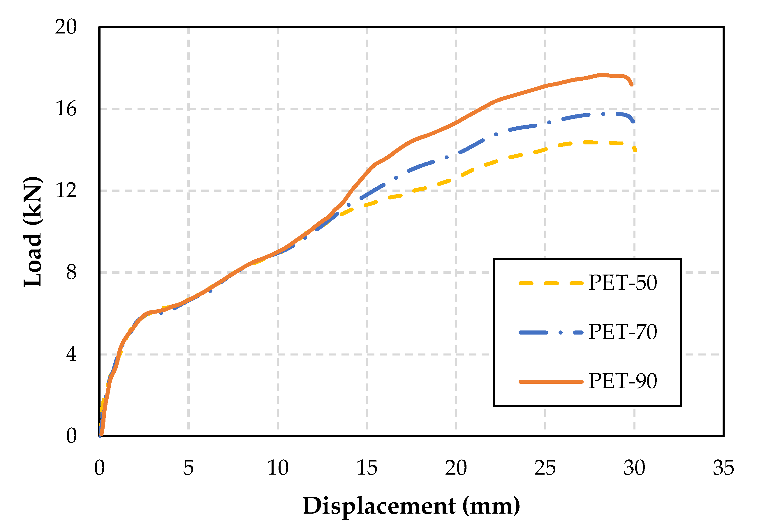
3.3. Parametric Study

The developed and validated model is employed to test the effect of different types of FRP composites on the flexural behavior of the slab with different concrete compressive strengths. The types of FRP composites inspected herein are CFRP, GFRP, BFRP and PET-FRP. Despite the fact that the elastic properties vary among the first three types, they all have a linear-elastic behavior up to rupture at their ultimate strain. However, the PET-FRP laminate has a bilinear behavior in which it has two moduli of elasticity [25], and they are both considered in the FE model. The mechanical properties of the investigated FRPs are presented in Table 2. The concrete compressive strength (f′c) was also varied for each type of FRP as follows: 50, 70 and 100 MPa. The first part of the specimen designation in Table 3 denotes the type of FRP, followed by the magnitude of the concrete compressive strength (f′c). For instance, C50 is a slab with a compressive strength of 50 MPa that is strengthened with one layer of CFRP laminate. PET-70 is a slab with a compressive strength of 70 MPa and strengthened with one layer of PET-FRP laminate.

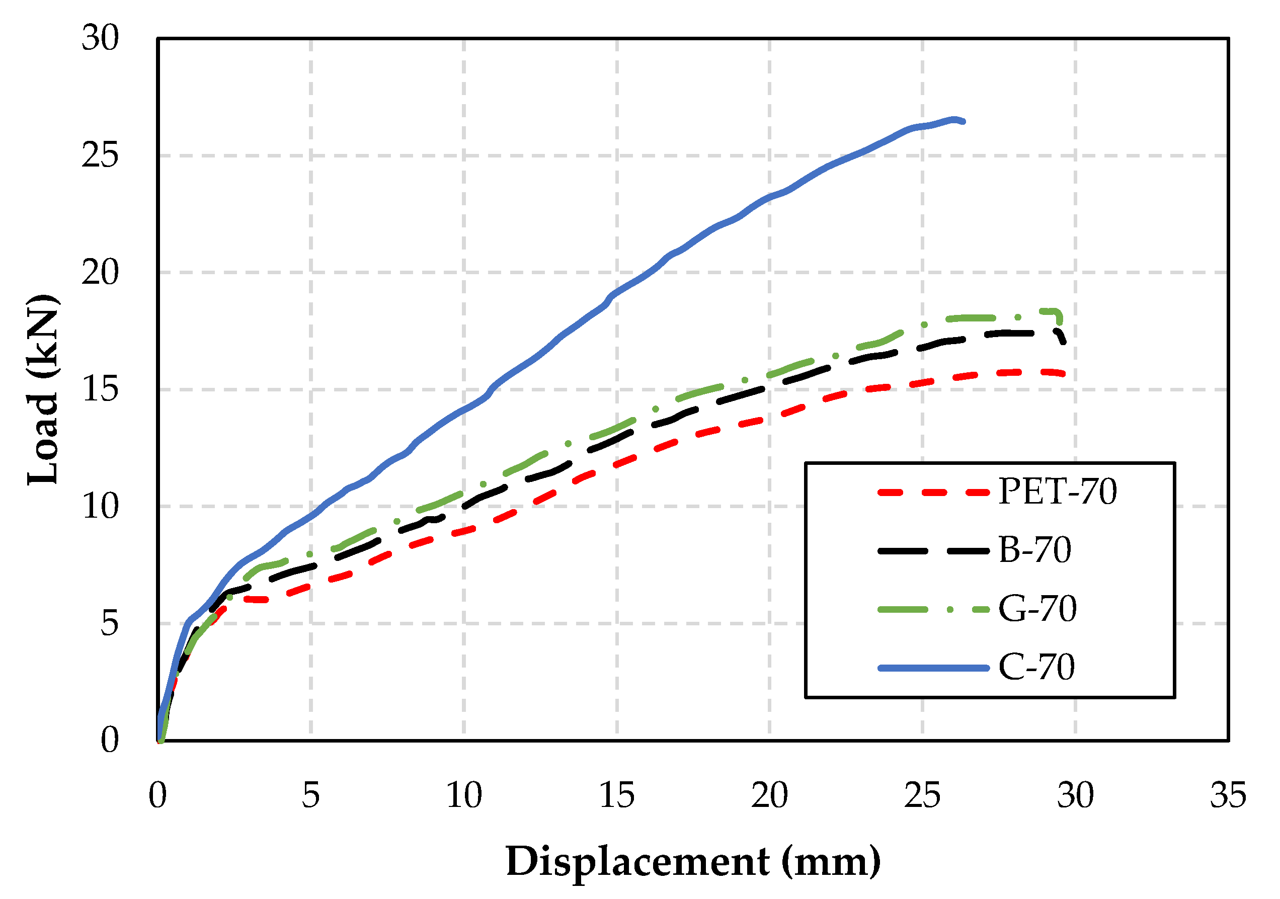
3.3.1. Effect of FRP Type

The effect of the FRP material on the flexural behavior of the strengthened slab was investigated by applying the mechanical properties of each FRP type in the FE model. Figure 7 shows the load-deflection behavior of four slab specimens, and each slab was externally bonded with a different type of FRP laminate. It can be noted that the highest strength enhancement among the four FRP types was obtained by CFRP, with a percentage increase in the ultimate load (Pu) of 191% compared to the control non-strengthened specimen. An almost similar flexural behavior was observed for the other three FRP types, with a percentage increase over the control specimen in Pu of 69%, 95% and 101% for PET-FRP, BFRP and GFRP, respectively. In terms of deflection, the CFRP-strengthened slab underwent a 9% lower ultimate deflection compared with the other strengthened slabs. It can also be noted from Figure 7 that the four slabs exhibited a similar stiffness regardless of the FRP type. Moreover, all slab specimens failed with steel yielding followed by FRP debonding, as expected. Thus, in order to utilize the tensile strength of the different laminates, especially with PET-FRP, such laminates need to be anchored with spike FRP anchors in a future investigation.

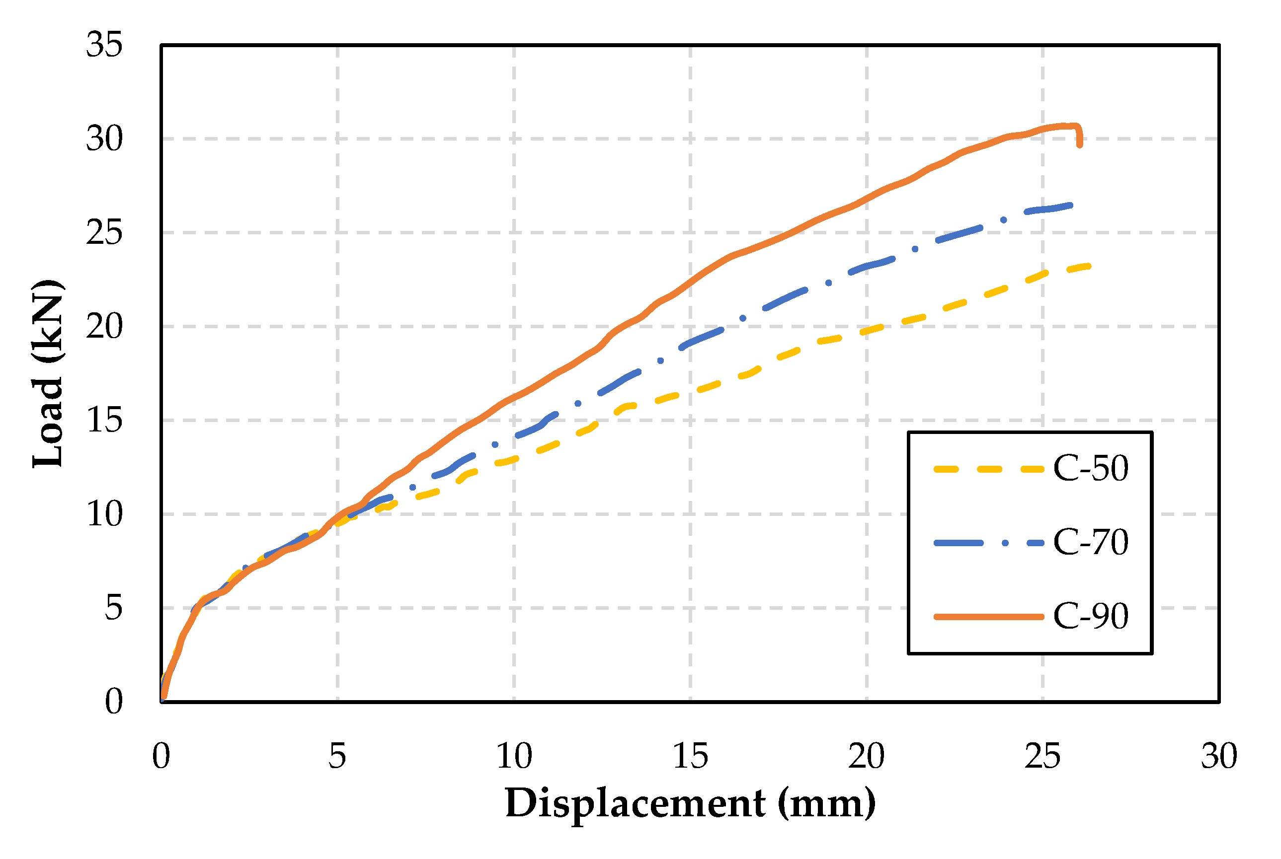
3.3.2. Effect of Concrete Compressive Strength (f′c)

In this section, the effect of the concrete compressive strength (f′c) on the performance of FRP-strengthened slabs was studied. For each FRP type, three values of f′c were investigated: 50, 70 and 90 MPa, respectively. Figure 8, Figure 9, Figure 10 and Figure 11 show the load-deflection curves for CFRP-, GFRP-, BFRP- and PET-FRP-strengthened slabs, respectively. It can be noted from these figures that the stiffness is the same for all FRP types and for all values of concrete strength. Moreover, the behavior for the three values of f′c is identical until a specific value of the displacement occurs. A moderate increase in the attained ultimate load is noted with the increase in f′c among slab specimens with the same FRP type, as can be seen from these figures. In Table 4, the percentage increase in ultimate load was calculated. The largest percentage difference in ultimate load is observed for the CFRP-strengthened slab, and it equals 15.8%.

4. Conclusions

This study reports on the flexural behavior of high-strength FRP-strengthened reinforced concrete slabs through numerical simulations of 3-D finite element (FE) models. CFRP strips were externally bonded to the soffit of the slab and tested under a two-point loading. The FE model was validated by comparing the load-deflection behavior, ultimate loads and deflections with previous results from previous experimental tests published by the two co-authors of this paper. A parametric study was then performed using the validated FE model to investigate the behavior and the extent of strength enhancement of different FRP types (GFRP, BFRP and PET-FRP). In addition, the concrete strength effect was examined for each FRP type. The following findings can be drawn from this study:
  • The FE model results agree well with the experimental data in terms of load-deflection behavior and flexural capacity, with a maximum percentage difference of 5.7% between the numerical and experimental ultimate loads;
  • For the same concrete compressive strength, the highest flexural capacity was obtained by the slabs that were strengthened with CFRP, while the remaining strengthened slabs (GFRP, BFRP and PET-FRP) showed an almost similar behavior;
  • The effect of concrete compressive strength on the behavior of the strengthened slabs was moderate, although it was more dominant in the CFRP-strengthened slabs.

Author Contributions

Conceptualization, M.A. and R.H.; methodology, M.A. and R.H.; software, M.A. and R.H.; validation, M.A. and R.H.; formal analysis, M.A.; investigation, M.A.; resources, R.H. and J.A.; data curation, M.A.; writing—original draft preparation, M.A.; writing—review and editing, R.H. and J.A.; visualization, R.H.; supervision, R.H. and J.A.; project administration, R.H.; funding acquisition, R.H. All authors have read and agreed to the published version of the manuscript.

Funding

This research received no external funding.

Institutional Review Board Statement

Not applicable.

Informed Consent Statement

Not applicable.

Data Availability Statement

Not applicable.

Conflicts of Interest

The authors declare no conflict of interest.

References

  1. Danraka, M.N.; Mahmod, H.M.; Oluwatosin, O.-K.J.; Student, P.G. Strengthening of Reinforced Concrete Beams using FRP Technique: A Review. Int. J. Eng. Sci. 2017, 7, 13199. [Google Scholar]
  2. Amran, Y.H.M.; Alyousef, R.; Rashid, R.S.M.; Alabduljabbar, H.; Hung, C.C. Properties and applications of FRP in strengthening RC structures: A review. In Structures; Elsevier Ltd.: Amsterdam, The Netherlands, 2018; Volume 16, pp. 208–238. [Google Scholar] [CrossRef]
  3. Naser, M.Z.; Hawileh, R.A.; Abdalla, J.A. Fiber-reinforced polymer composites in strengthening reinforced concrete structures: A critical review. Eng. Struct. 2019, 198, 109542. [Google Scholar] [CrossRef]
  4. Choobbor, S.S.; Hawileh, R.A.; Abu-Obeidah, A.; Abdalla, J.A. Performance of hybrid carbon and basalt FRP sheets in strengthening concrete beams in flexure. Compos. Struct. 2019, 227, 111337. [Google Scholar] [CrossRef]
  5. Hawileh, H.H.M.R.A.; Abuzaid, W.; Naser, M.Z.; Abdalla, J.A. Experimental Investigation and Modeling of the Thermal Effect on the Mechanical Properties of Polyethylene-Terephthalate FRP Laminates. J. Mater. Civ. Eng. 2006, 32, 04020296. [Google Scholar] [CrossRef]
  6. Hawileh, R.A.; Musto, H.A.; Abdalla, J.A.; Naser, M.Z. Finite element modeling of reinforced concrete beams externally strengthened in flexure with side-bonded FRP laminates. Compos. Part B Eng. 2019, 173, 106952. [Google Scholar] [CrossRef]
  7. Naser, M.Z.; Hawileh, R.A.; Abdalla, J.A.; Al-Tamimi, A. Bond behavior of CFRP cured laminates: Experimental and numerical investigation. J. Eng. Mater. Technol. 2012, 134, 021002. [Google Scholar] [CrossRef]
  8. ACI Committee 318. Building Code Requirements for Structural Concrete: (ACI 318-95); and Commentary (ACI 318R-95); American Concrete Institute: Farmington Hills, MI, USA, 1995. [Google Scholar]
  9. Mahmoud, H.S.; Hawileh, R.A.; Abdalla, J.A. Strengthening of high strength reinforced concrete thin slabs with CFRP laminates. Compos. Struct. 2021, 275, 114412. [Google Scholar] [CrossRef]
  10. Torabian, A.; Isufi, B.; Mostofinejad, D.; Ramos, A.P. Flexural strengthening of flat slabs with FRP composites using EBR and EBROG methods. Eng. Struct. 2020, 211, 110483. [Google Scholar] [CrossRef]
  11. Salman, W.D.; Mansor, A.; Mahmood, M.; Mansor, A.A. Reinforced Concrete One-Way Slabs Strengthened by Cfrp Sheets in Flexural Zone. Int. J. Civ. Eng. Technol. 2018, 9, 1872–1881. [Google Scholar]
  12. Zhu, Y.; Zhang, Y.; Hussein, H.H.; Chen, G. Flexural strengthening of reinforced concrete beams or slabs using ultra-high performance concrete (UHPC): A state of the art review. Eng. Struct. 2020, 205, 110035. [Google Scholar] [CrossRef]
  13. Ebead, U.A.; Marzouk, H. Fiber-Reinforced Polymer Strengthening of Two-Way Slabs Use of FRCM systems in strengthening applications. ACI Struct. J. 2004, 101, 650–659. [Google Scholar]
  14. Inácio, M.M.G.; Lapi, M.; Ramos, A.P. Punching of reinforced concrete flat slabs—Rational use of high strength concrete. Eng. Struct. 2020, 206, 110194. [Google Scholar] [CrossRef]
  15. Hawileh, R.A. Nonlinear finite element modeling of RC beams strengthened with NSM FRP rods. Constr. Build. Mater. 2012, 27, 461–471. [Google Scholar] [CrossRef]
  16. Chen, G.M.; Teng, J.G.; Chen, J.F.; Xiao, Q.G. Finite element modeling of debonding failures in FRP-strengthened RC beams: A dynamic approach. Comput. Struct. 2015, 158, 167–183. [Google Scholar] [CrossRef]
  17. Naser, M.Z.; Hawileh, R.A.; Abdalla, J. Modeling strategies of finite element simulation of reinforced concrete beams strengthened with frp: A review. J. Compos. Sci. 2021, 5, 19. [Google Scholar] [CrossRef]
  18. Hawileh, R.A.; El-Maaddawy, T.A.; Naser, M.Z. Nonlinear finite element modeling of concrete deep beams with openings strengthened with externally-bonded composites. Mater. Des. 2012, 42, 378–387. [Google Scholar] [CrossRef]
  19. Hawileh, R.A. Finite element modeling of reinforced concrete beams with a hybrid combination of steel and aramid reinforcement. Mater. Des. 2015, 65, 831–839. [Google Scholar] [CrossRef]
  20. ANSYS. A Finite Element Computer Software and User Manual for Nonlinear Structural Analysis; Release Version 19.2, 2019; ANSYS Inc.: Canonsburg, PA, USA, 2019. [Google Scholar]
  21. ANSYS, Inc. Theory Reference ANSYS Release 9.0 002114 November 2004 ANSYS, Inc. Is a UL Registered ISO 9001: 2000 Comp. Available online: https://vdoc.pub/documents/ansys-inc-theory-reference-ansys-release-90-2e2gnh6i7mcg (accessed on 1 January 2022).
  22. Nakaba, K.; Kanakubo, T.; Furuta, T.; Yoshizawa, H. Bond Behavior between Fiber-Reinforced Polymer Laminates and Concrete. Struct. J. 2001, 3, 359–367. [Google Scholar]
  23. Hognestad, E.; Hlanson, N.W.; McHenry, D. Concrete Stress Distribution in Ultimate Strength Design. ACI J. Proc. 1955, 52, 455–480. [Google Scholar]
  24. Willam, K.J.; Warnke, E.D. Constitutive Model for the Triaxial Behavior of Concrete. Proc. Intl. Assoc. Bridge Structl. Engrs 1975, 19, 1–30. [Google Scholar]
  25. Hawileh, R.A.; Mhanna, H.H.; al Rashed, A.; Abdalla, J.A.; Naser, M.Z. Flexural behavior of RC beams externally bonded with polyethylene terephthalate (PET) fiber reinforced polymer (FRP) laminates. Eng. Struct. 2022, 256, 114036. [Google Scholar] [CrossRef]
  26. Chiew, S.-P.; Asce, M.; Sun, Q.; Yu, Y. Flexural Strength of RC Beams with GFRP Laminates. J. Compos. Constr. 2007, 11, 497–506. [Google Scholar] [CrossRef]
  27. Smith, S.T.; Teng, J.G.; FRP-Strengthened RC Beams. I: Review of Debonding Strength Models. 2002. Available online: www.elsevier.com/locate/engstruct (accessed on 1 January 2022).
  28. Smith, S.T.; Teng, J.G.; FRP-Strengthened RC Beams. II: Assessment of Debonding Strength Models. 2002. Available online: www.elsevier.com/locate/engstruct (accessed on 1 January 2020).
Figure 1. Geometrical configuration and test setup of the tested slab: (a) Elevation and location of loading; (b) Cross section of the slab.
Jcs 06 00263 g001
Figure 2. Developed FE model components in ANSYS: (a) 3D view; (b) boundary conditions; (c) bottom view.
Jcs 06 00263 g002
Figure 3. Bond-slip model used to simulate interfacial behavior between FRP and concrete.
Jcs 06 00263 g003
Figure 4. Constitutive models for concrete with f′c of 70 MPa: (a) Compressive stress-strain curve; (b) tensile stress-strain curve.
Jcs 06 00263 g004
Figure 5. Load-deflection curves from FE model and experimental test [10]: (a) Control slab; (b) C1; (c) C2.
Jcs 06 00263 g005aJcs 06 00263 g005b
Figure 6. Failure mode of a slab specimen strengthened with one CFRP layer: (a) Experiment [10]; (b) FE model.
Jcs 06 00263 g006
Figure 7. Effect of FRP type on the load-deflection behavior of a strengthened slab specimen.
Jcs 06 00263 g007
Figure 8. Effect of concrete compressive strength on the behavior of CFRP-strengthened slabs.
Jcs 06 00263 g008
Figure 9. Effect of concrete compressive strength on the behavior of GFRP-strengthened slabs.
Jcs 06 00263 g009
Figure 10. Effect of concrete compressive strength on the behavior of BFRP-strengthened slabs.
Jcs 06 00263 g010
Figure 11. Effect of concrete compressive strength on the behavior of PET-FRP-strengthened slabs.
Jcs 06 00263 g011
Table 1. Comparison between experimental and FE model’s results.
SpecimenPu (Exp) (kN)Pu (FE)
(kN)
% ErrorUmax (Exp)
(mm)
Umax (FE)
(mm)
% Error
Control9.18.83.33.53.7−5.7
C126.426.5−0.428.226.36.7
C240.142.4−5.721.822.0−0.9
Table 2. Mechanical properties of the investigated FRP laminates.
FRP TypeE (GPa)Tensile Strength (MPa)Thickness (mm)
CFRP [10]7312401.02
GFRP [26]27 5251.3
BFRP [5]174110.72
PET-FRP [25]E1 = 20
E2 = 9
7700.84
Table 3. Parametric study test matrix.
ModelFRP TypeConcrete Compressive Strength (MPa)
C-50CFRP50
C-70CFRP70
C-90CFRP90
G-50GFRP50
G-70GFRP70
G-90GFRP90
B-50BFRP50
B-70BFRP70
B-90BFRP90
PET-50PET-FRP50
PET-70PET-FRP70
PET-90PET-FRP90
Table 4. Numerical predicted results.
ModelPu (kN)% Increase
C-5023.2-
C-7026.514.2
C-9030.715.8
G-5016.5-
G-7018.310.9
G-9020.19.8
B-5015.5-
B-7017.512.9
B-9018.87.4
PET-5013.8-
PET-7015.411.6
PET-9017.211.7
Publisher’s Note: MDPI stays neutral with regard to jurisdictional claims in published maps and institutional affiliations.

