3D-Printed Carbon Fiber Reinforced Polymer Composites: A Systematic Review


Abstract
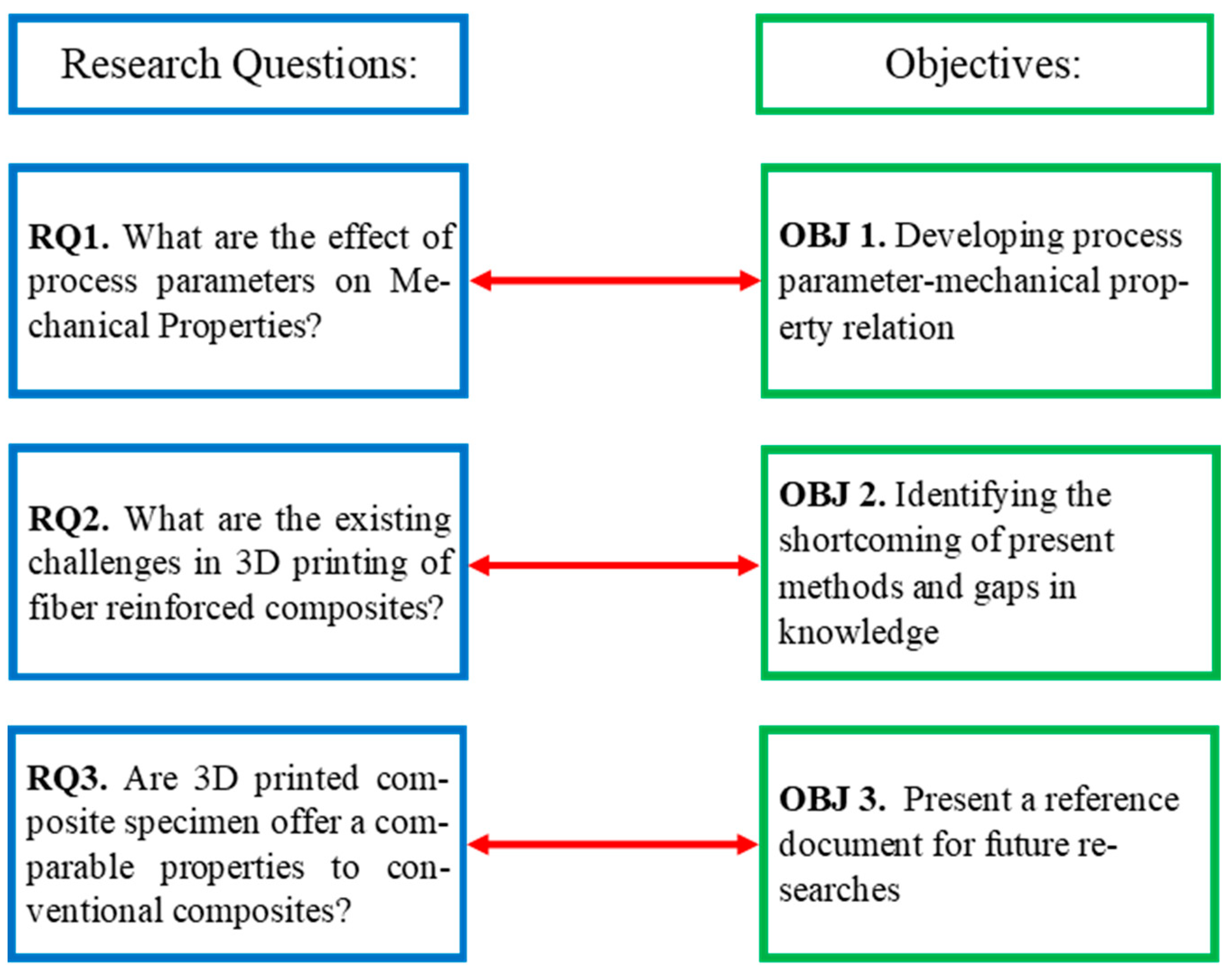
:1. Introduction
3D Printing Fiber Reinforced Polymer Composites
- (1)
- Improving the mechanical properties of 3DP fiber reinforced composites by:
- (a)
- (b)
- (c)
- (2)
- (3)
- Applying the current knowledge to functional parts [7].
2. Data and Method
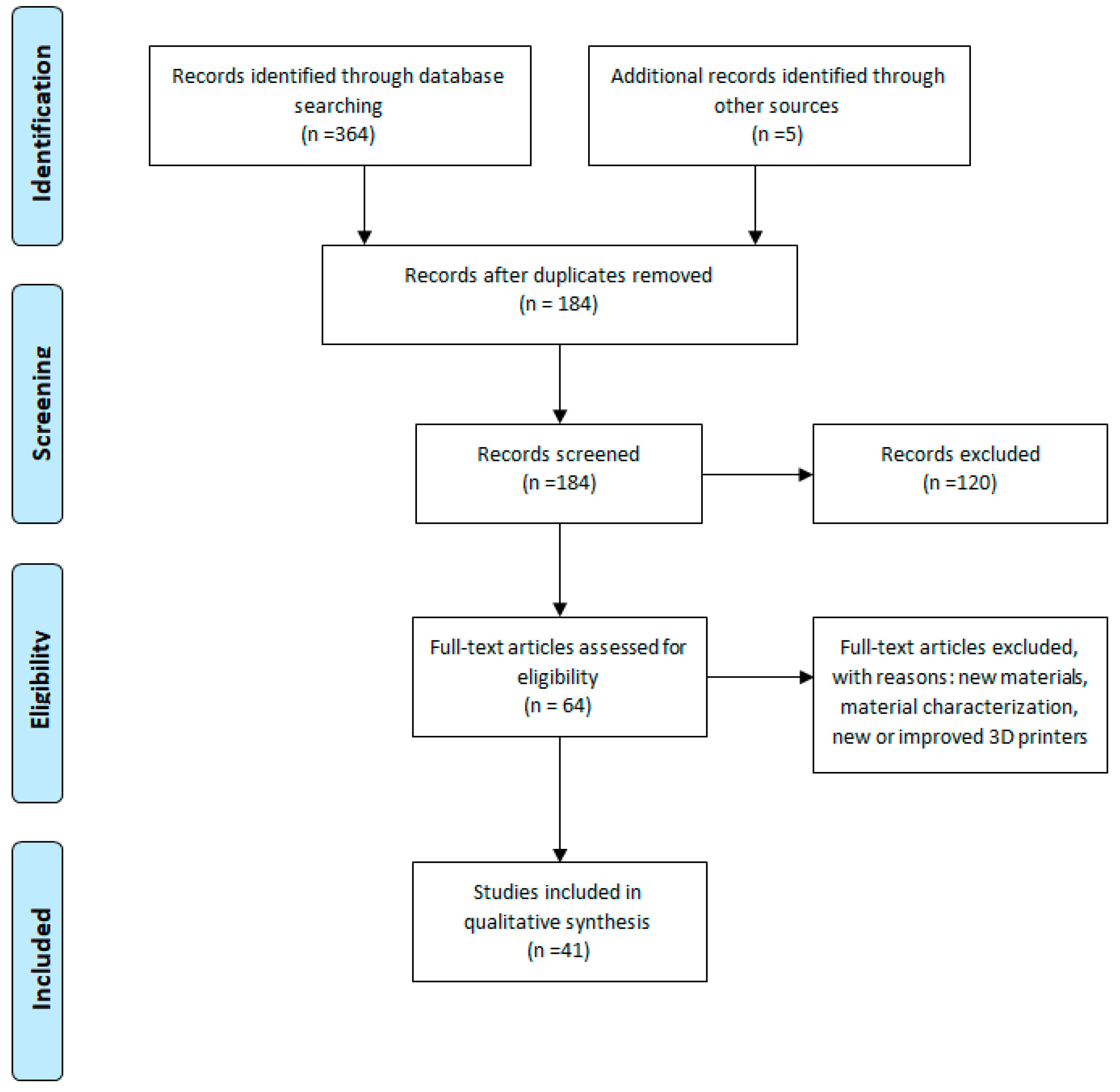
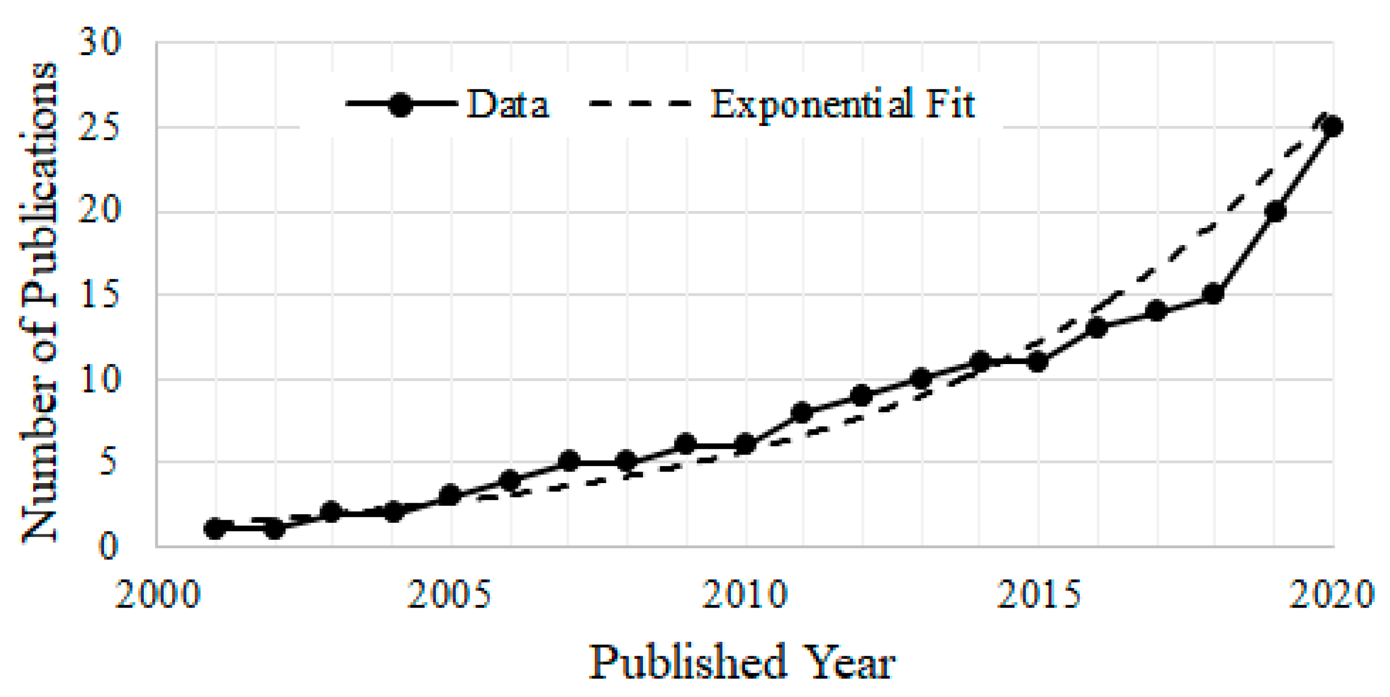
2.1. Search Strategy
2.2. Eligibility Criteria
2.3. Records Management, Data Quality and Data Extraction
3. Results and Discussions
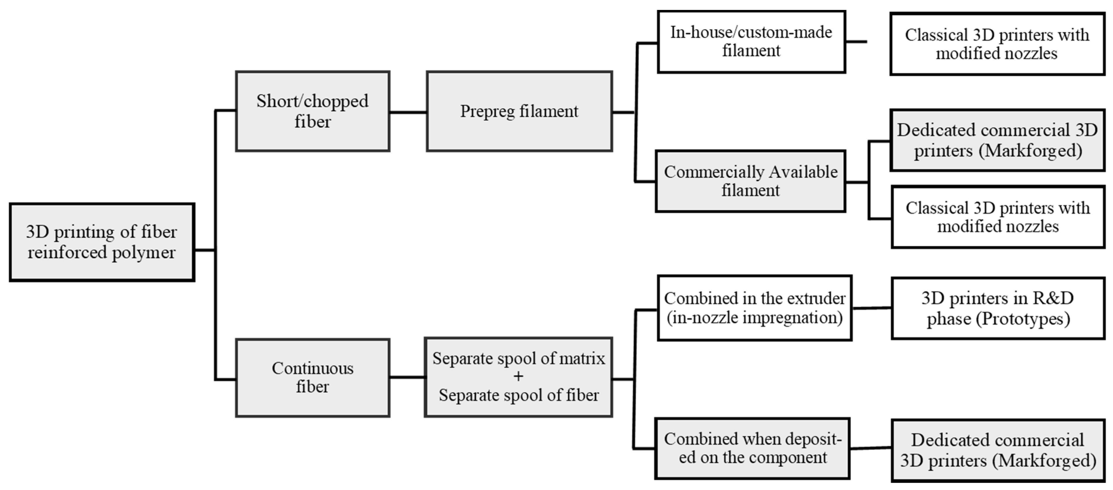
3.1. 3D Printing Carbon Reinforced Polymers
3.1.1. Continuous Fiber Fabrication—Markforged Printers
3.1.2. In-Nozzle Impregnation
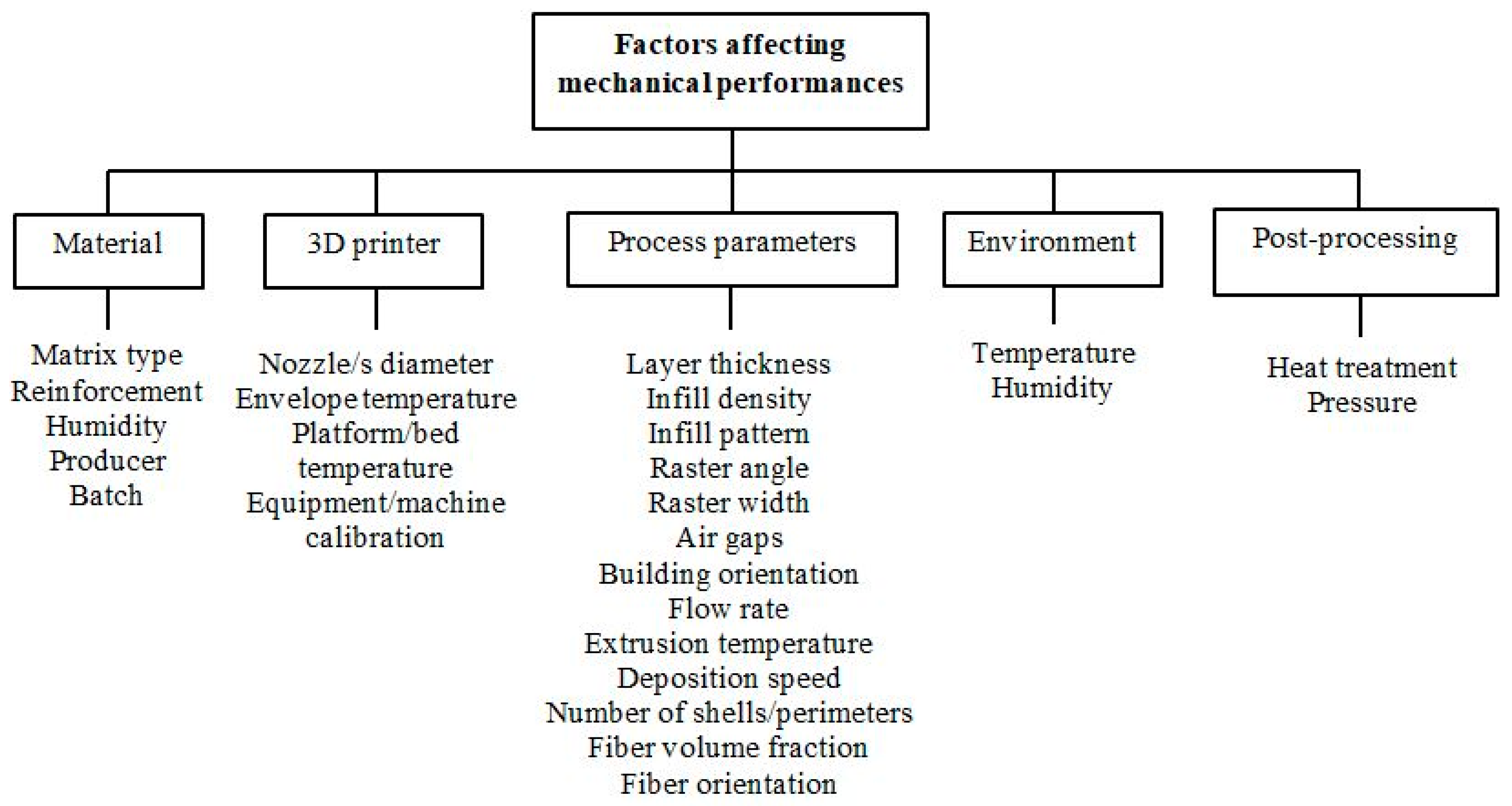
3.2. 3D Printing Process Parameters for Fiber Reinforced Composites
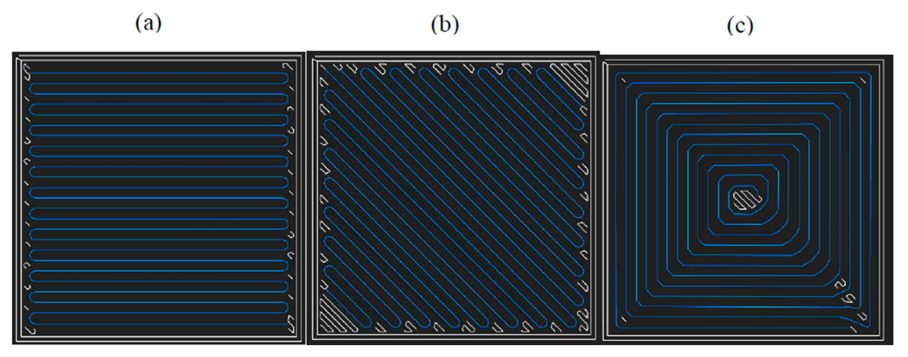
3.2.1. Infill Pattern and Density
3.2.2. Fiber Orientation, Volume Fraction and Stacking Sequence
3.2.3. Build Orientation
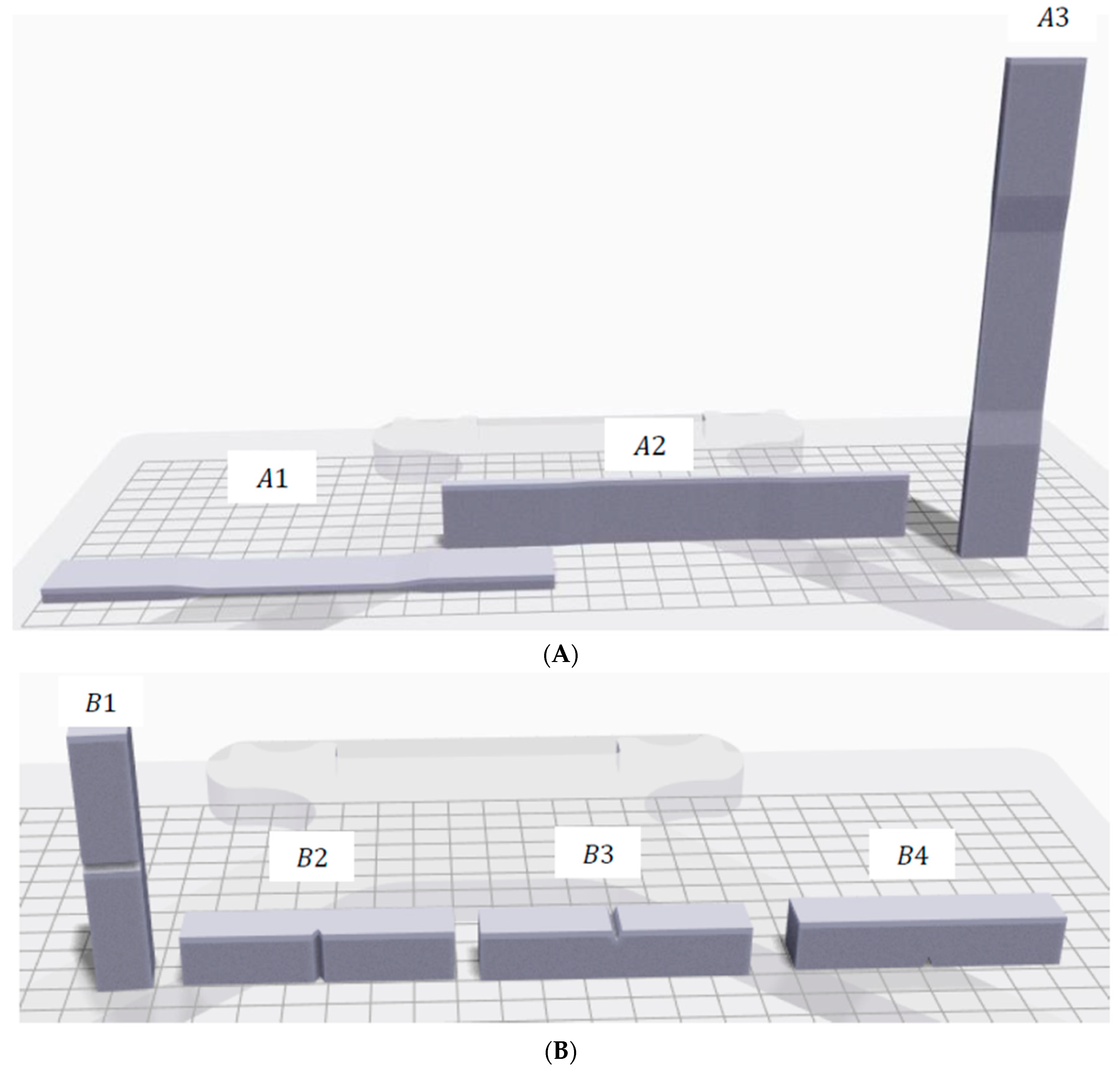
3.2.4. Specimens Design and Tabs
3.2.5. Start/End Point of Fibers
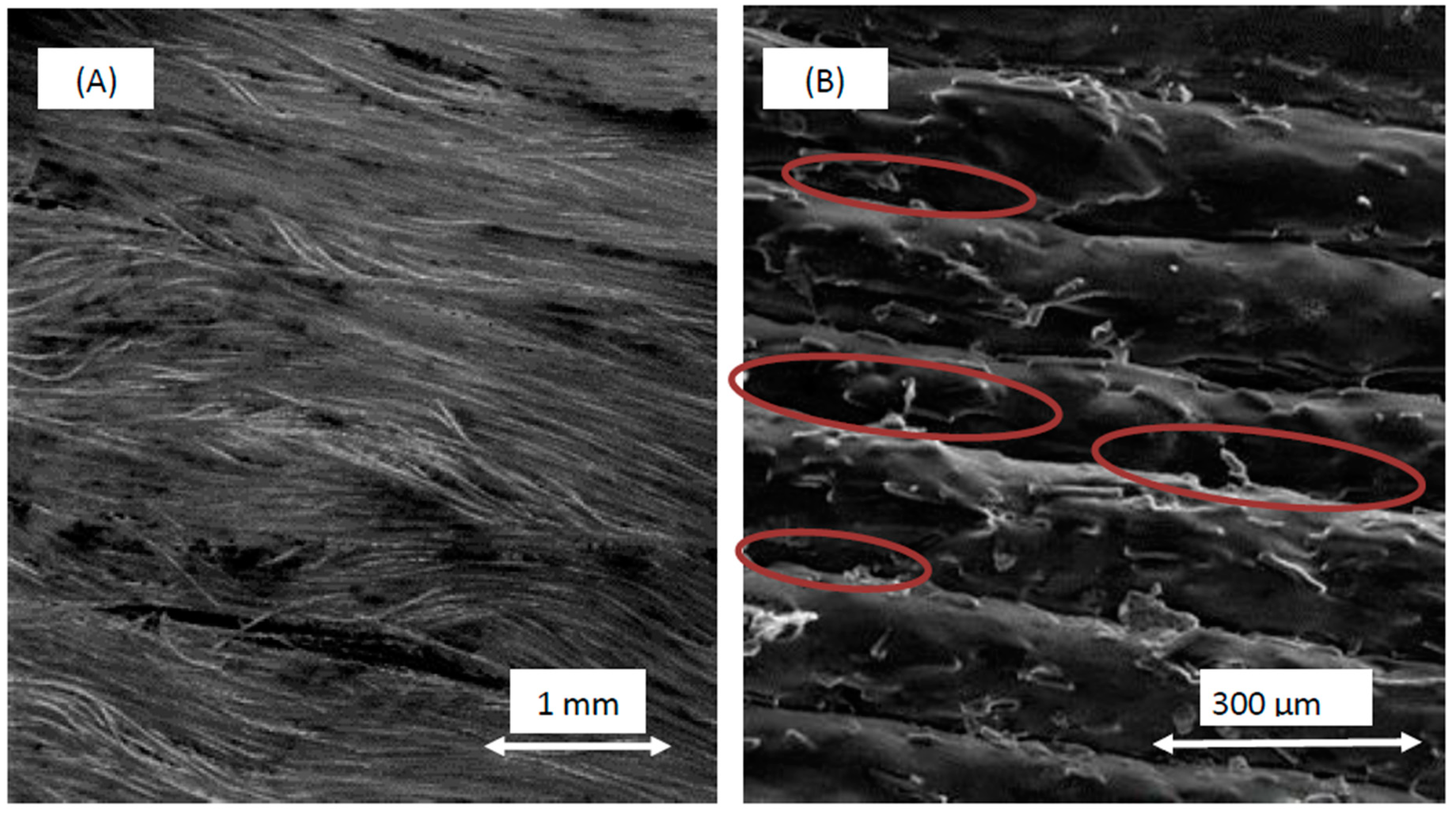
3.3. Defects in 3D-Printed Composite Specimens
3.4. Specimen Size Effect
3.5. Micromechanical Models
3.5.1. Voigt Model
3.5.2. Reuss Model
3.5.3. Halpin–Tsai Model
3.5.4. Volume Average Stiffness (VAS) Method
3.5.5. Generalized Self-Consistent Method
4. Concluding Remarks and Future Suggestions
- (1)
- 3DP of composite materials offers a great potential for manufacturing functional parts beyond prototyping due to exceptional specific stiffness and strength that composites are known for with the addition of unique features of 3DP such as printing concentric fibers around notches to mitigate stress concentration, changing the print process parameter to tailor the mechanical properties.
- (2)
- The lack of reporting details makes the comparison between different research efforts challenging. In many instances, information about the infill pattern, infill density, fiber volume fraction, number of floor/roof were left out, each of which could result in noticeable difference in the resulted mechanical properties. Authors would like to take a note to authors/reviewers to ensure the inclusion of such details for the reproducibility of their findings.
- (3)
- A limited research has been conducted on the quantification of defects and their contribution to the overall mechanical properties, voids formation at different length scale has been the major reported defect in the literature.
- (4)
- Large uncertainty present in the specimen microstructures renders the deterministic analysis invalid, and a stochastic predictive model must be developed. Authors did not find any stochastic analysis linking microstructural uncertainty to mechanical property variability for 3D-printed continuous fiber composites.
- (5)
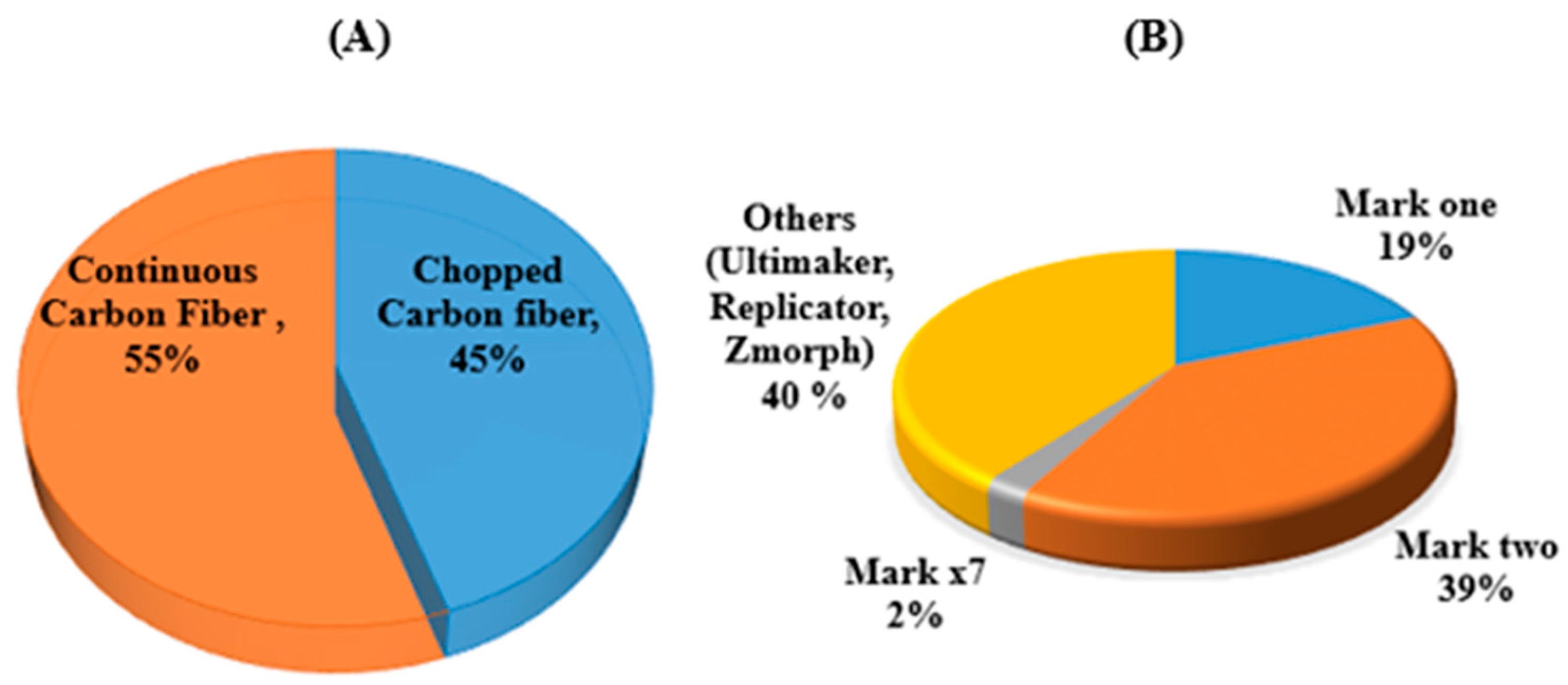
- Despite many patents on the topic [64], to this date, Markforged printers are the only commercially available 3D printers for manufacturing continuous fiber composites. Poor adhesion between fiber and matrix layer, lack of tension in fibers, presence of void, limited choice of matrix material (nylon and onyx) are the reported restricted factors.
- (6)
- It has been reported that for a given fiber volume fraction, consolidating fiber layers compared to alternating fiber/matrix layers will enhance the mechanical properties.
- (7)
- The use of concentric fiber rings is the unique capability of 3DP that has been used to optimize the mechanical properties and mitigate stress concentration.
- (8)
- Triangular pattern shows higher mechanical properties compared to rectangular or hexagonal patterns. It was also observed that infill density is not largely influencing the tensile yield strength nor the ultimate strength while reducing elongation and significantly affecting the printing time and cost.
- (9)
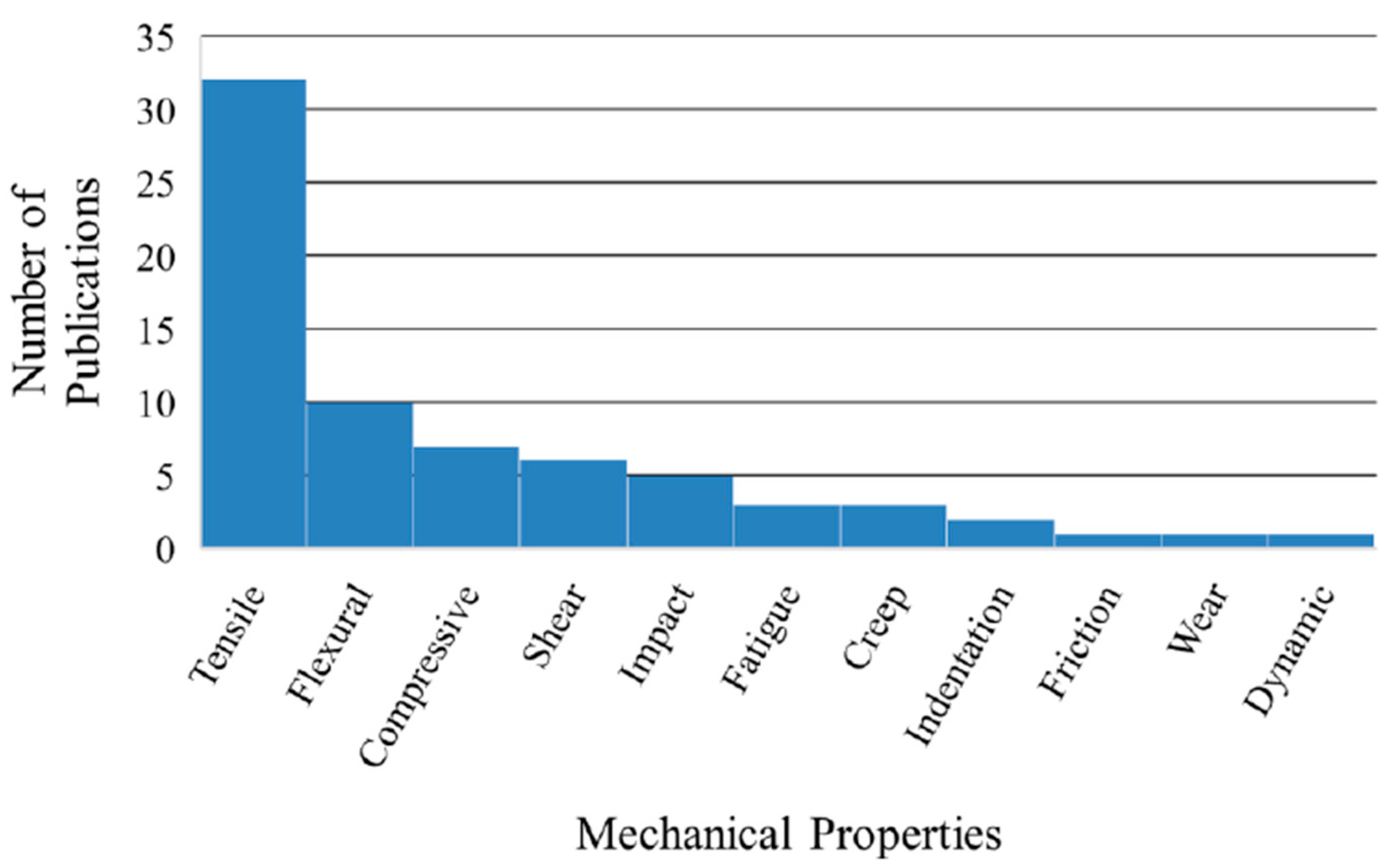
- Tensile strength is the most studied mechanical property for both short and continuous reinforced 3D-printed composites followed by flexural, compressive and shear.
- (10)
- All studies are focused on experimental coupons with no reports on parts in service when exposed to sterilization, light, aging or humidity.
- (11)
- Given the large number of processing parameter needed be selected in printing composite samples, an artificial intelligence (AI) approach in optimizing said parameters to get desirable outcome would be the next milestone in 3D printing of composite materials.
- (12)
- Specific design rules need to be developed for 3D-printed fiber reinforced composite parts as significant rise in the number of studies in the field is expected in the next couple of years, triggered by the industry interest and sustained by the researchers and equipment developers’ work.
Funding
Conflicts of Interest
References
- Kabir, S.M.F.; Mathur, K.; Seyam, A.F.M. A critical review on 3D printed continuous fiber-reinforced composites: History, mechanism, materials and properties. Compos. Struct. 2020, 232, 111476. [Google Scholar] [CrossRef]
- Brenken, B.; Barocio, E.; Favaloro, A.; Kunc, V.; Pipes, R.B. Fused filament fabrication of fiber-reinforced polymers: A review. Addit. Manuf. 2018, 21, 1–16. [Google Scholar] [CrossRef]
- Zak, G.; Sela, M.N.; Park, C.B.; Benhabib, B. A layered manufacturing of fiber reinforced composites. J. Manuf. Sci. Eng. 1999, 121, 448–456. [Google Scholar] [CrossRef]
- Araya-Calvo, M.; López-Gómez, I.; Chamberlain-Simon, N.; León-Salazar, J.L.; Guillén-Girón, T.; Corrales-Cordero, J.S.; Sánchez-Brenes, O. Evaluation of compressive and flexural properties of continuous fiber fabrication additive manufacturing technology. Addit. Manuf. 2018, 22, 157–164. [Google Scholar] [CrossRef]
- Blok, L.G.; Longana, M.L.; Yu, H.; Woods, B.K.S.S. An investigation into 3D printing of fibre reinforced thermoplastic composites. Addit. Manuf. 2018, 22, 176–186. [Google Scholar] [CrossRef]
- Caminero, M.A.; Chacón, J.M.; García-Moreno, I.; Rodríguez, G.P. Impact damage resistance of 3D printed continuous fibre reinforced thermoplastic composites using fused deposition modelling. Compos. Part B Eng. 2018, 148, 93–103. [Google Scholar] [CrossRef]
- Chacón, J.M.; Caminero, M.A.; Núñez, P.J.; García-Plaza, E.; García-Moreno, I.; Reverte, J.M. Additive manufacturing of continuous fibre reinforced thermoplastic composites using fused deposition modelling: Effect of process parameters on mechanical properties. Compos. Sci. Technol. 2019, 181, 107688. [Google Scholar] [CrossRef]
- Naranjo-Lozada, J.; Ahuett-Garza, H.; Orta-Castañón, P.; Verbeeten, W.M.H.; Sáiz-González, D. Tensile properties and failure behavior of chopped and continuous carbon fiber composites produced by additive manufacturing. Addit. Manuf. 2019, 26, 227–241. [Google Scholar] [CrossRef]
- Sanei, S.H.R.; Arndt, A.; Doles, R. Open hole tensile testing of 3D printed continuous carbon fiber reinforced composites. J. Compos. Mater. 2020. [Google Scholar] [CrossRef]
- Mohammadizadeh, M.; Imeri, A.; Fidan, I.; Elkelany, M. 3D printed fiber reinforced polymer composites-Structural analysis. Compos. Part B Eng. 2019, 175, 107112. [Google Scholar] [CrossRef]
- Oztan, C.; Karkkainen, R.; Fittipaldi, M.; Nygren, G.; Roberson, L.; Lane, M.; Celik, E. Microstructure and mechanical properties of three dimensional-printed continuous fiber composites. J. Compos. Mater. 2019, 53, 271–280. [Google Scholar] [CrossRef]
- Ning, F.; Cong, W.; Qiu, J.; Wei, J.; Wang, S. Additive manufacturing of carbon fiber reinforced thermoplastic composites using fused deposition modeling. Compos. Part B Eng. 2015, 80, 369–378. [Google Scholar] [CrossRef]
- Melenka, G.W.; Cheung, B.K.O.O.; Schofield, J.S.; Dawson, M.R.; Carey, J.P. Evaluation and prediction of the tensile properties of continuous fiber-reinforced 3D printed structures. Compos. Struct. 2016, 153, 866–875. [Google Scholar] [CrossRef]
- Matsuzaki, R.; Ueda, M.; Namiki, M.; Jeong, T.K.; Asahara, H.; Horiguchi, K.; Nakamura, T.; Todoroki, A.; Hirano, Y. Three-dimensional printing of continuous-fiber composites by in-nozzle impregnation. Sci. Rep. 2016, 6, 1–7. [Google Scholar] [CrossRef] [PubMed]
- Al Abadi, H.; Thai, H.T.; Paton-Cole, V.; Patel, V.I. Elastic properties of 3D printed fibre-reinforced structures. Compos. Struct. 2018, 193, 8–18. [Google Scholar] [CrossRef]
- Ferreira, R.T.L.; Amatte, I.C.; Dutra, T.A.; Bürger, D. Experimental characterization and micrography of 3D printed PLA and PLA reinforced with short carbon fibers. Compos. Part B Eng. 2017, 124, 88–100. [Google Scholar] [CrossRef]
- Somireddy, M.; Singh, C.V.; Czekanski, A. Mechanical behaviour of 3D printed composite parts with short carbon fiber reinforcements. Eng. Fail. Anal. 2020, 107, 1–13. [Google Scholar] [CrossRef]
- van de Werken, N.; Tekinalp, H.; Khanbolouki, P.; Ozcan, S.; Williams, A.; Tehrani, M. Additively manufactured carbon fiber-reinforced composites: State of the art and perspective. Addit. Manuf. 2020, 31, 100962. [Google Scholar] [CrossRef]
- Popescu, D.; Zapciu, A.; Amza, C.; Baciu, F.; Marinescu, R. FDM process parameters influence over the mechanical properties of polymer specimens: A review. Polym. Test. 2018, 69, 157–166. [Google Scholar] [CrossRef]
- Liberati, A.; Altman, D.G.; Tetzlaff, J.; Mulrow, C.; Gøtzsche, P.C.; Ioannidis, J.P.A.; Clarke, M.; Devereaux, P.J.; Kleijnen, J.; Moher, D. The PRISMA Statement for Reporting Systematic Reviews and Meta-Analyses of Studies That Evaluate Health Care Interventions: Explanation and Elaboration. PLoS Med. 2009, 6, e1000100. [Google Scholar] [CrossRef]
- González-Estrada, O.A.; Pertuz, A.; Quiroga, J. Evaluation of tensile properties and damage of continuous fibre reinforced 3D-printed parts. Key Eng. Mater. 2018, 774, 161–166. [Google Scholar] [CrossRef] [Green Version]
- Imeri, A.; Fidan, I.; Allen, M.; Wilson, D.A.; Canfield, S. Fatigue analysis of the fiber reinforced additively manufactured objects. Int. J. Adv. Manuf. Technol. 2018, 98, 2717–2724. [Google Scholar] [CrossRef]
- Todoroki, A.; Oasada, T.; Mizutani, Y.; Suzuki, Y.; Ueda, M.; Matsuzaki, R.; Hirano, Y. Tensile property evaluations of 3D printed continuous carbon fiber reinforced thermoplastic composites. Adv. Compos. Mater. 2020, 29, 147–162. [Google Scholar] [CrossRef]
- Dickson, A.N.; Barry, J.N.; McDonnell, K.A.; Dowling, D.P. Fabrication of continuous carbon, glass and Kevlar fibre reinforced polymer composites using additive manufacturing. Addit. Manuf. 2017, 16, 146–152. [Google Scholar] [CrossRef]
- Dutra, T.A.; Ferreira, R.T.L.; Resende, H.B.; Guimarães, A. Mechanical characterization and asymptotic homogenization of 3D-printed continuous carbon fiber-reinforced thermoplastic. J. Braz. Soc. Mech. Sci. Eng. 2019, 41. [Google Scholar] [CrossRef]
- Sarvestani, A.N.; Werken, N.; van de Khanbolouki, P.; Tehrani, M. 3D Printed Composites with Continuous Carbon Fiber Reinforcements. In Proceedings of the ASME 2017 International Mechanical Engineering Congress and Exposition, Tampa, FL, USA, 3–9 November 2017; pp. 1–6. [Google Scholar]
- Yu, T.; Zhang, Z.; Song, S.; Bai, Y.; Wu, D. Tensile and flexural behaviors of additively manufactured continuous carbon fiber-reinforced polymer composites. Compos. Struct. 2019, 225. [Google Scholar] [CrossRef]
- Frank, V.D.K.; Koga, Y.; Todoroki, A.; Ueda, M.; Hirano, Y.; Matsuzaki, R. 3D Printing of Continuous Carbon Fibre Reinforced Thermo-Plastic (CFRTP) Tensile Test Specimens. Open J. Compos. Mater. 2016, 6, 18–27. [Google Scholar] [CrossRef] [Green Version]
- Pyl, L.; Kalteremidou, K.A.; Van Hemelrijck, D. Exploration of specimen geometry and tab configuration for tensile testing exploiting the potential of 3D printing freeform shape continuous carbon fibre-reinforced nylon matrix composites. Polym. Test. 2018, 71, 318–328. [Google Scholar] [CrossRef]
- Yasa, E.; Ersoy, K. Dimensional Accuracy and Mechanical Properties of Chopped Carbon Reinforced Polymers Produced by Material Extrusion Additive Manufacturing. Materials 2019, 12, 3885. [Google Scholar] [CrossRef] [Green Version]
- Yasa, E. Anisotropic impact toughnness of chopped carbon fiber reinforced nylon fabricated by material-extrusion-based additive manufacturing. Anadolu Univ. J. Sci. Technol. Appl. Sci. Eng. 2019, 20, 195–203. [Google Scholar] [CrossRef]
- de Toro, E.V.; Sobrino, J.C.; Martínez, A.M.; Eguía, V.M.; Pérez, J.A. Investigation of a short carbon fibre-reinforced polyamide and comparison of two manufacturing processes: Fused Deposition Modelling (FDM) and polymer injection moulding (PIM). Materials 2020, 13, 672. [Google Scholar] [CrossRef] [PubMed] [Green Version]
- Abdullah, A.M.; Mohamad, D.; Rahim, T.N.A.T.; Akil, H.M.; Rajion, Z.A. Effect of narrow infill density gap on the compressive properties of 3D printed carbon fibre reinforced acrylonitrile butadiene styrene. J. Mech. Sci. Technol. 2019, 33, 2339–2343. [Google Scholar] [CrossRef]
- Mohammadizadeh, M.; Fidan, I.; Allen, M.; Imeri, A. Creep behavior analysis of additively manufactured fiber-reinforced components. Int. J. Adv. Manuf. Technol. 2018, 99, 1225–1234. [Google Scholar] [CrossRef]
- Bakis, C.E.; Haluza, R.T.; Bartolai, J.; Kim, J.J.; Simpson, T.W. Assessment of anisotropic mechanical properties of a 3D printed carbon whisker reinforced composite. Adv. Compos. Mater. 2019, 28, 545–560. [Google Scholar] [CrossRef]
- Tezel, T.; Kovan, V.; Topal, E.S. Effects of the printing parameters on short-term creep behaviors of three-dimensional printed polymers. J. Appl. Polym. Sci. 2019, 136, 6–11. [Google Scholar] [CrossRef]
- Wang, K.; Li, S.; Rao, Y.; Wu, Y.; Peng, Y.; Yao, S.; Zhang, H.; Ahzi, S. Flexure behaviors of ABS-based composites containing carbon and Kevlar fibers by material extrusion 3D printing. Polymers 2019, 11, 1878. [Google Scholar] [CrossRef] [PubMed] [Green Version]
- Durga Prasada Rao, V.; Rajiv, P.; Navya Geethika, V. Effect of fused deposition modelling (FDM) process parameters on tensile strength of carbon fibre PLA. Mater. Today Proc. 2019, 18, 2012–2018. [Google Scholar] [CrossRef]
- Ding, Q.; Li, X.; Zhang, D.; Zhao, G.; Sun, Z. Anisotropy of poly(lactic acid)/carbon fiber composites prepared by fused deposition modeling. J. Appl. Polym. Sci. 2020, 137, 1–11. [Google Scholar] [CrossRef]
- Ivey, M.; Melenka, G.W.; Carey, J.P.; Ayranci, C. Characterizing short-fiber-reinforced composites produced using additive manufacturing. Adv. Manuf. Polym. Compos. Sci. 2017, 3, 81–91. [Google Scholar] [CrossRef] [Green Version]
- Akasheh, F.; Aglan, H. Fracture toughness enhancement of carbon fiber–reinforced polymer composites utilizing additive manufacturing fabrication. J. Elastomers Plast. 2019, 51, 698–711. [Google Scholar] [CrossRef]
- Ferreira, I.; Vale, D.; Machado, M.; Lino, J. Additive manufacturing of polyethylene terephthalate glycol /carbon fiber composites: An experimental study from filament to printed parts. Proc. Inst. Mech. Eng. Part L J. Mater. Des. Appl. 2019, 233, 1866–1878. [Google Scholar] [CrossRef]
- Ghebretinsae, F.; Mikkelsen, O.; Akessa, A.D. Strength analysis of 3D printed carbon fibre reinforced thermoplastic using experimental and numerical methods. IOP Conf. Ser. Mater. Sci. Eng. 2019, 700. [Google Scholar] [CrossRef]
- Giannakis, E.; Koidis, C.; Kyratsis, P.; Tzetzis, D. Static and fatigue properties of 3D printed continuous carbon fiber nylon composites. Int. J. Mod. Manuf. Technol. 2019, 11, 69–76. [Google Scholar]
- Goh, G.D.; Dikshit, V.; Nagalingam, A.P.; Goh, G.L.; Agarwala, S.; Sing, S.L.; Wei, J.; Yeong, W.Y. Characterization of mechanical properties and fracture mode of additively manufactured carbon fiber and glass fiber reinforced thermoplastics. Mater. Des. 2018, 137, 79–89. [Google Scholar] [CrossRef]
- Iragi, M.; Pascual-Gonzalez, C.; Esnaola, A.; Aurrekoetxea, J.; Lopes, C.S.; Aretxabaleta, L. Characterization of elastic and resistance behaviours of 3D printed continuous carbon fibre reinforced thermoplastics. In Proceedings of the ECCM 2018-18th European Conference on Composite Materials, Athens, Greece, 25–28 June 2018; pp. 24–28. [Google Scholar]
- Jiang, D.; Smith, D.E. Anisotropic mechanical properties of oriented carbon fiber filled polymer composites produced with fused filament fabrication. Addit. Manuf. 2017, 18, 84–94. [Google Scholar] [CrossRef]
- Justo, J.; Távara, L.; García-Guzmán, L.; París, F. Characterization of 3D printed long fibre reinforced composites. Compos. Struct. 2018, 185, 537–548. [Google Scholar] [CrossRef]
- Mansour, M.; Tsongas, K.; Tzetzis, D.; Antoniadis, A. Mechanical and Dynamic Behavior of Fused Filament Fabrication 3D Printed Polyethylene Terephthalate Glycol Reinforced with Carbon Fibers. Polym.-Plast. Technol. Eng. 2018, 57, 1715–1725. [Google Scholar] [CrossRef]
- Patterson, A.E.; Pereira, T.R.; Allison, J.T.; Messimer, S.L. IZOD impact properties of full-density fused deposition modeling polymer materials with respect to raster angle and print orientation. Proc. Inst. Mech. Eng. Part C J. Mech. Eng. Sci. 2019. [Google Scholar] [CrossRef]
- Sanei, S.H.R.; Lash, Z.; Servey, J.; Gardone, F.; Nikhare, C.P. Mechanical properties of 3D printed fiber reinforced thermoplastic. ASME Int. Mech. Eng. Congr. Expo. Proc. 2019, 12. [Google Scholar] [CrossRef]
- Croccolo, D.; De Agostinis, M.; Olmi, G. Experimental characterization and analytical modelling of the mechanical behaviour of fused deposition processed parts made of ABS-M30. Comput. Mater. Sci. 2013, 79, 506–518. [Google Scholar] [CrossRef]
- Laureto, J.J.; Pearce, J.M. Anisotropic mechanical property variance between ASTM D638-14 type i and type iv fused filament fabricated specimens. Polym. Test. 2018, 68, 294–301. [Google Scholar] [CrossRef] [Green Version]
- Farhang, L.; Fernlund, G. Void and porosity characterization of uncured and partially cured prepregs. J. Compos. Mater. 2016, 50, 937–948. [Google Scholar] [CrossRef]
- Nikishkov, Y.; Airoldi, L.; Makeev, A. Measurement of voids in composites by X-ray Computed Tomography. Compos. Sci. Technol. 2013, 89, 89–97. [Google Scholar] [CrossRef]
- Little, J.E.; Yuan, X.; Jones, M.I. Characterisation of voids in fibre reinforced composite materials. NDT E Int. 2012, 46, 122–127. [Google Scholar] [CrossRef]
- Christensen, R.; Miyano, Y.; Nakada, M. The size dependence of tensile strength for brittle isotropic materials and carbon fiber composite materials. Compos. Sci. Technol. 2015, 106, 9–14. [Google Scholar] [CrossRef]
- Sanei, S.H.R.; Fertig, R.S. Uncorrelated volume element for stochastic modeling of microstructures based on local fiber volume fraction variation. Compos. Sci. Technol. 2015, 117, 191–198. [Google Scholar] [CrossRef]
- Sanei, S.H.R.; Barsotti, E.J.; Leonhardt, D.; Fertig, R.S. Characterization, synthetic generation, and statistical equivalence of composite microstructures. J. Compos. Mater. 2017, 51, 1817–1829. [Google Scholar] [CrossRef]
- Kregers, A.F.; Zilauts, A.F. Limiting values of reinforcement factors for fibrous composites with a three-dimensional structure. Mech. Compos. Mater. 1985, 20, 530–536. [Google Scholar] [CrossRef]
- Kregers, A.F.; Teters, G.A. Determination of the elastoplastic properties of spatially reinforced composites by the averaging method. Mech. Compos. Mater. 1981, 17, 25–31. [Google Scholar] [CrossRef]
- Kreger, A.F.; Teters, G.A. Use of averaging methods to determine the viscoelastic properties of spatially reinforced composites. Mech. Compos. Mater. 1980, 15, 377–383. [Google Scholar] [CrossRef]
- Christensen, R.M. Effective properties of composite materials containing voids. Proc. R. Soc. Lond. Ser. A Math. Phys. Sci. 1993, 440, 461–473. [Google Scholar] [CrossRef]
- Hu, C.; Sun, Z.; Xiao, Y.; Qin, Q. Recent Patents in Additive Manufacturing of Continuous Fiber Reinforced Composites. Recent. Patents Mech. Eng. 2019, 12, 25–36. [Google Scholar] [CrossRef]


| Process Parameter | Published Research |
|---|---|
| Fiber orientation (unidirectional, concentric) | [4,10,21,22,23,24,25,26,27] |
| Fiber volume fraction | [4,6,7,8,11,21,24,26,27] |
| Stacking sequence (Angle ply, cross-ply, balanced, symmetric) | [4,6,7,28,29] |
| Matrix infill pattern (triangular, rectangular, hexagonal) | [8,21,23,30,31,32] |
| Infill density | [8,30,32,33] |
| Number of concentric fiber rings | [8,22,26,27,34] |
| Raster angle | [35,36,37,38] |
| Layer thickness | [6,7,17,36,39] |
| Build orientation | [6,7,30,31,37,39] |
| Platform temperature | [32] |
| Printing temperature | [38,39] |
| Deposition speed | [39] |
| Annealing temperature | [40] |
| Study | Research Objective | Analyzed Parameters | Material | Short/Continuous Fiber | 3D Printer | Studied Mech. Prop | Specimen Design |
|---|---|---|---|---|---|---|---|
| Abdullah et al. [33] | Mechanical properties evaluation | Infill density | ABS/15% CF | Short | Makerbot Replicator 2 | Compressive | ASTM D695 |
| Akasheh et al. [41] | Reinforcement schemes for improving fracture toughness | Reinforcement pattern | Onyx, Onyx/CF | Both | MarkTwo | Tensile, residual stiffness, fracture behavior | ASTM D638, ASTM D3039 |
| Al Abadi et al. [15] | Evaluation of elastic properties of fiber-reinforced polymers, prediction model based on volume average stress | N/A | Nylon/CF, glass, Kevlar | Continuous | MarkOne | Tensile | ASTM D303 |
| Araya-Calvo et al. [4] | Parameters optimization for improving mechanical properties | Reinforcement pattern, fiber orientation, build orientation, fiber volume content, stacking sequence | Onyx/CF | Continuous | MarkTwo | Compressive, flexural | ASTM D695, ASTM D790 |
| Bakis et al. [35] | Anisotropy evaluation | Raster angle, fiber volume | PLA/Cw | Short | MendelMax 3 | Tensile | Custom rectangular specimen |
| Blok et al. [5] | Mechanical properties comparison of short and continuous CF composites | N/A | 27% Nylon/CF, Nylon/6 wt % short CF | Both | MarkOne, Lulzbot TAZ | Tensile, flexural, in-plane shear | ASTM D638, ASTM D7264, ASTM D3518 |
| Caminero et al. [6] | Process parameter influence on impact resistance | Layer thickness, fiber volume content, build orientation, stacking sequence | Nylon/CF, GF, KF | Continuous | MarkTwo | Impact | ASTM D6110 |
| Chacon et al. [7] | Process parameter influence on mechanical properties | Layer thickness, fiber volume content, build orientation, stacking sequence | Nylon/CF, GF, KF | Continuous | MarkTwo | Tensile, flexural | ASTM D3039, ASTM D790 |
| Dickson et al. [24] | Process parameter influence on mechanical properties | Fiber orientation, fiber volume content, fiber type | Nylon/CF, GF, KF | Continuous | MarkOne | Tensile, flexural | ASTM D3039, ASTM D790 |
| Ding et al. [39] | Process parameter influence on mechanical properties | Printing temperature, printing speed, build orientation, layer thickness | PLA/ 20% CF | Short | U-print machine A8 | Tensile, impact, friction, wear | ASTM D638, Rectangular unnotched 60 mm × 9.5 mm × 3.5 mm |
| Dutra et al. [25] | Mechanical properties investigation, prediction model based on asymptotic homogenization technique | Fiber orientation | Nylon/CF | Continuous | MarkOne | Tensile (longitudinal transverse), compression (longitudinal), in-plane shear | ASTM D3039, ASTM D638, ASTM D6641, ASTM D3518 |
| Ferreira et al. [16] | Mechanical properties evaluation | Raster angle | PLA/15% CF | Short | BQ Prusa270i3 Hephesto | Tensile, in-plane shear | ASTM D638 ASTM D3518 |
| Ferreira et al. [42] | Mechanical properties evaluation | N/A | PETG/20% CF | Short | Tronxy X5 | Tensile, flexural | ISO-527, ISO-178 |
| Ghebretinsae et al. [43] | Mechanical properties evaluation | N/A | Onyx/CF | Continuous | MarkTwo | Tensile, flexural | ASTM D3039, (250 mm × 15 mm × 1.75 mm) ASTM D7264 |
| Giannakis et al. [44] | Mechanical properties evaluation (PLA, Nylon, Nylon/CF comparison) | N/A | Nylon/CF, PLA, Nylon | Continuous | BCN3D, MarkTwo | Tensile, fatigue | ASTM D3039, custom specimens |
| Goh et al. [45] | Mechanical properties evaluation | N/A | Nylon/41% CF | Continuous | MarkOne | Tensile, flexural, quasi-static indentation | ASTM D3039, ASTM D790, ASTM D6264 |
| Gonzalez-Estrada et al. [21] | Process parameter influence on mechanical properties | Fiber orientation, fiber volume content, infill pattern, | Nylon/CF, GF, KF | Continuous | MarkTwo | Tensile | ASTM D638, type IV |
| Imeri et al. [22] | Process parameter influence on mechanical properties | Fiber orientation, infill pattern, fiber type, number of rings | Nylon/CF, GF, KF | Continuous | MarkTwo | Fatigue | ASTM E606M |
| Iraqi et al. [46] | Mechanical properties evaluation | N/A | Onyx/CF | Continuous | MarkTwo | Tensile, in-plane shear, interlaminar shear | ASTM D3039, ASTM D518, ASTM D2344 |
| Ivey et al. [40] | Mechanical properties evaluation, annealing temperature effect on tensile properties | Annealing temperature | PLA/15% CF | Short | RoVa3D 5 | Tensile | ASTM D638-14 type V |
| Jiang et al. [47] | Anisotropy evaluation, materials comparison | Raster angle | PLA/CF, ABS/CF, PETG/CF, Amphora/CF | Short | Makerbot Replicator 2x | Tensile | ASTMD638 type I |
| Justo et al. [48] | Mechanical properties evaluation | N/A | Nylon/CF | Continuous | MarkOne | Tensile, compressive, in-plane shear | ASTM D3039, ASTM D695-02a, ASTM D3518 |
| Mansour et al. [49] | Mechanical and dynamic properties evaluation | N/A | PETG/20% CF | Short | Zmorph SX FDM | Compressive, cyclic compressive, nanoindentation | Custom cylindrical specimens |
| Mohammadizadeh et al. [34] | Creep investigations | N/A | Nylon/CF, GF, KF | Continuous | MarkTwo | Creep, dynamic thermal analysis | ASTM D-2990-17 |
| Mohammadizadeh et al. [10] | Structural analysis | Fiber type, fiber orientation, number of rings, temperature | Nylon/CF, GF, KF | Continuous | MarkTwo | Tensile, fatigue, creep | ASTM D638-14 type I ASTM E606M, ATSM D2990-17 |
| Naranjo-Losada et al. [8] | Mechanical properties evaluation, predictive model based on RoM | Infill density, infill pattern, fiber volume content, reinforcement pattern, number or rings | PA6, Onyx, Nylon/CF | Both | MarkTwo | Tensile | ASTM D638-14 Type I |
| Oztan et al. [11] | Mechanical properties evaluation, predictive model based on RoM | N/A | PLA, CF, KF, Nylon | Continuous | MarkOne, Ultimaker 2 | Tensile | ASTM D3039 |
| Patterson et al. [50] | Process parameter influence on mechanical properties | Raster angle, print orientation | ABS, PLA, HIPS, PETG, PC, Nylon, AlPLA, WPLA, HTPLA, PLA/15% CF | Short | Prusa | Impact | ASTM D256 type E |
| Pyl et al. [29] | Process parameter influence on mechanical properties | Different specimens design, fiber orientation, stacking sequence | Nylon/CF | Continuous | MarkTwo | Tensile, in-plane shear | ASTM D638-14 Type I, ASTM D638 type IV, ASTM D638 type IV modified, ASTM D3039 |
| Rao et al. [38] | Mechanical properties evaluation | Layer thickness, extrusion temperature, infill pattern | PLA/CF | Short | Ultimaker | Tensile | ASTMD638 type I |
| Sanei et al. [51] | Mechanical properties evaluation | Fiber orientation | Onyx | Continuous | Markedforged X7 | Tensile | ASTM D3039 |
| Sarvesani et al. [26] | Mechanical properties and electrical conductivity evaluation | Fiber volume fraction, number of rings | Nylon/CF | Continuous | MarkTwo | Tensile | ASTM D638-14 Type I, ASTM D638-14 Type IV, ASTM D3039 |
| Somirredy et al. [17] | Mechanical properties evaluation, predictive model based on laminate theory | Raster angle, layer thickness | ABS/CF | Short | Ultimaker | Tensile, interlaminar fracture toughness | ASTM D303, ASTM D5528 |
| Tezel et al. [36] | Process parameter influence on mechanical properties | Raster angle, layer thickness | PLA/15% CF | Short | Zmorph | Creep | ASTM D638 Type IV |
| Todoroki et al. [23] | Process parameter influence on mechanical properties | Fiber orientation | Nylon/CF | Continuous | MarkTwo | Tensile | Custom specimens with no surface layers |
| van der Klift [28] | MarkOne 3D printer benchmark | Stacking sequence, | Nylon/34.5% CF | Continuous | MarkOne | Tensile | JIS K 7073 |
| de Toro et al. [32] | Mechanical properties evaluation, comparison 3DP and injection molding | Infill pattern, infill density | PA6/ 20 wt % CF | Short | Ultimaker 2 | Tensile, flexural, compressive | Custom specimens |
| Wang et al. [37] | Mechanical properties evaluation | Raster orientation, build orientation | ABS, ABS/CF, ABS/KF, ABS/CF/KF | Short | Raise3D N2 | Flexural | Rectangular custom specimens |
| Yasa et al. [30] | Mechanical properties and dimensional accuracy evaluation | Infill density, build orientation, infill pattern | Onyx | Short | MarkTwo | Tensile | ASTM D638 |
| Yasa et al. [31] | Mechanical properties evaluation, comparison to injection molding | Infill density, build orientation, fill pattern | Onyx | Short | MarkTwo | Impact | ISO 179 |
| Yu et al. [27] | Process parameter influence on mechanical properties, predictive model | Infill pattern, fiber volume fraction | Onyx/CF | Continuous | MarkOne | Tensile, flexural | Custom dogbone design ASTM D6272-17 |
© 2020 by the authors. Licensee MDPI, Basel, Switzerland. This article is an open access article distributed under the terms and conditions of the Creative Commons Attribution (CC BY) license (http://creativecommons.org/licenses/by/4.0/).
Share and Cite
Sanei, S.H.R.; Popescu, D. 3D-Printed Carbon Fiber Reinforced Polymer Composites: A Systematic Review. J. Compos. Sci. 2020, 4, 98. https://doi.org/10.3390/jcs4030098
Sanei SHR, Popescu D. 3D-Printed Carbon Fiber Reinforced Polymer Composites: A Systematic Review. Journal of Composites Science. 2020; 4(3):98. https://doi.org/10.3390/jcs4030098
Chicago/Turabian StyleSanei, Seyed Hamid Reza, and Diana Popescu. 2020. "3D-Printed Carbon Fiber Reinforced Polymer Composites: A Systematic Review" Journal of Composites Science 4, no. 3: 98. https://doi.org/10.3390/jcs4030098