Article

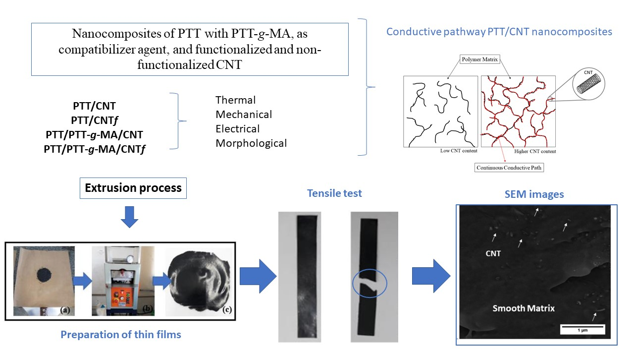
Effect of Carbon Nanotubes (CNT) Functionalization and Maleic Anhydride-Grafted Poly(trimethylene terephthalate) (PTT-g-MA) on the Preparation of Antistatic Packages of PTT/CNT Nanocomposites

by
Natália Ferreira Braga
*,
Henrique Morales Zaggo
,
Larissa Stieven Montagna
and
Fabio Roberto Passador
Polymer and Biopolymer Technology Laboratory (TecPBio), Department of Science and Technology, Federal University of São Paulo (UNIFESP), 330 Talim, São José dos Campos SP 12231-280, Brazil
*
Author to whom correspondence should be addressed.
J. Compos. Sci. 2020, 4(2), 44; https://doi.org/10.3390/jcs4020044
Submission received: 26 March 2020 / Revised: 20 April 2020 / Accepted: 22 April 2020 / Published: 24 April 2020
(This article belongs to the Special Issue Carbon-Based Polymer Nanocomposites)

Abstract

:
Electronic devices require the use of antistatic packing to prevent electrostatic discharge during their storage or transport. Poly (trimethylene terephthalate) (PTT) is a polyester with excellent properties and can be a good candidate for this application. To make this insulating polymer an extrinsic conductor, carbon nanotubes (CNT) can be added to reduce the electrical resistivity of the nanocomposites. In order to facilitate the CNT distribution on polymeric matrix, it was proposed a chemical functionalization using nitric acid for the creation of functional groups on its surface. Moreover, the PTT matrix was modified with a compatibilizer agent based on maleic anhydride grafted PTT (PTT-g-MA), to improve interfacial adhesion between the nanofiller and matrix. In this work, nanocomposites based on PTT/PTT-g-MA/CNT were prepared by extrusion process, with 0.5 wt% and 1.0 wt% of CNT and functionalized CNT. CNT was characterized by stability dispersion in water, Raman spectroscopy, FTIR and XPS analysis, which prove the success of functionalization. The nanocomposites were evaluated by thermal analysis, tensile tests, electrical conductivity, and morphological analysis. The CNT functionalization and the addition of PTT-g-MA increased the dispersion and distribution of CNT in the PTT matrix. The electrical properties show that this material can be used as an antistatic packaging.

Graphical Abstract

1. Introduction

Polymers have increasingly stood out from other materials in the packaging industry when considering factors such as cost-effectiveness and design possibilities [1]. However, in the production of antistatic packaging for storage and transport of electronic components and devices, the insulating characteristic of the most polymers can result in electrostatic tensions accumulation, which, if not dissipated, can generate electrostatic discharge (ESD) capable of damaging and invalidating the product [1,2]. Many studies associate several polymers such as polyvinyl chloride (PVC) [3], low-density polyethylene (LDPE) [4], polyurethane (PU) [5], poly(lactic acid) (PLA) [6], polyamide 6/linear low-density polyethylene blends (PA6/LLDPE) [7], and aromatic polyesters such as poly(ethylene terephthalate) (PET) [8,9] and poly(trimethylene terephthalate)/acrylonitrile butadiene styrene blends (PTT/ABS) [10] as excellent candidates for the preparation of antistatic packaging.
In this work, PTT was investigated as a polymeric matrix for the preparation of antistatic packages. Exhibiting great characteristics as PET and poly (butylene terephthalate) (PBT), PTT differs by the presence of three methylene groups in their main chain, a characteristic which results in higher chains flexibility and faster crystallization compared to PET [11,12]. Furthermore, PTT combines the mechanical properties of PET, the processability of PBT and the elasticity of polyamide [11,13,14]. Such properties allow this polymer to be used in the textile industry [15], in fibers [16], polymeric film production [17], or engineering thermoplastics applications [18].
As well as in various polymers, a dissipative character can be attributed to PTT by adding functional fillers (antistatic agents) into the polymeric matrix. These additives may range from metallic particles [19] and intrinsically conductor polymers, such as polyaniline [20] and polypyrrole [21], to different carbon materials as carbon black [6,22], graphene [23], carbon fibers [24,25], glassy carbon [4], and carbon nanotubes (CNT) [26].
CNT is an interesting alternative as an antistatic agent due to its unique electrical characteristics: depending on its hexagonal structure orientation, it can have conductive behavior like a metal [27]. CNT presents electrical properties essential to upgrade polymer’s electrical conductivity [28], and CNT/polymer composites have been studying since the first researches in this area [29,30,31]. Moreover, the CNTs are widely applicable to engineering projects due to their low density, excellent thermal properties, and good mechanical properties such as high stiffness, tensile strength, and reasonable ductility [27]. However, the agglomeration tendency of CNTs [28,32,33] may have an influence on their properties transferring to the polymeric matrix during nanocomposites production, justifying the use of functionalization techniques in the optimization of their distributions on the polymer matrix [34]. Gupta et. al. [26] fabricated PTT with multiwall carbon nanotube (MWCNT) nanocomposites by melt compounding. The electrical conductivity of composites was increased by increasing the content of MWCNT and a typical percolation behavior was observed at 0.48 vol%, which indicates the formation of interconnected networks of a small quantity of this nanofiller in the polymer matrix. Ma et al. [35], studied the properties of PTT/MWCNT prepared by electrospinning. The addition of MWCNT resulted in an increase in the RAF (rigid amorphous fraction), which indicated an enhancement in the restrictions on the polymer chains in PTT composites nanofibers due to the decrease of chain mobility. Szymczyk et al. [36] prepared nanocomposites based on PTT and functionalized CNT with COOH groups by in-situ polymerization method. Regarding mechanical analysis, in comparison with neat PTT, the MWCNT reinforced nanocomposites showed higher tensile strength and Young’s modulus at a low content of MWCNT.
As a complement of the functionalization process, the use of compatibilizer agents in polymer/CNT nanocomposites favored a more homogeneous dispersion and a better interaction of CNT with the polymer matrix [10,37]. Compatibilizer agents act in the reduction of interfacial tensions present in blends and composites, resulting in improved interfacial adhesion between the matrix and the disperse phase [37,38,39]. Several works mention the use of compatibilizer agents obtained from grafting reactions of maleic anhydride in polymers such as polyethylene (PE-g-MA) [40], polypropylene (PP-g-MA) [38], poly(hydroxybutyrate-co-hydroxy valerate) (PHBV-g-MA) [41] and PTT (PTT-g-MA) [10,39,42].
There are some works in the literature regarding PTT/CNT nanocomposites [43,44,45,46,47], including work concerning acrylic acid-grafted PTT (PTT-g-AA) [48], but until now, few works have been reported involving the use of the compatibilizer agent, PTT-g-MA, and functionalized and non-functionalized CNT [42]. The compatibilizer agent PTT-g-MA was successfully obtained in our previous work [39] from reactive extrusion of PTT with the addition of benzoyl peroxide and maleic anhydride.
The main goal of this present study was to develop a novel nanocomposite of PTT based-CNT and functionalized CNT (CNTf) with the addition of a compatibilizer agent, PTT-g-MA to improve the compatibility and dispersion of CNT on the polymer matrix. The nanocomposites were prepared using the extrusion process and the films were prepared by hot pressing. The effect of the functionalization of CNT and the addition of PTT-g-MA on the thermal, mechanical, morphological, and electrical properties of nanocomposites were evaluated.

2. Experimental

2.1. Materials

Poly (trimethylene terephthalate) (PTT), with specification Corterra 200, was supplied by Shell Chemicals (Montreal, QC, Canada), with a density of 1.35 g/cm3.
Multi-wall carbon nanotubes (MWCNT) supplied by NanocylTM S.A. (Sambreville, Belgium) with trade name NC7000, with a minimum purity of 90%, average diameter and length 9.5 nm and 1.5 μm, respectively, produced by the chemical catalytic vapor deposition (CCVD) process, according to the supplier’s technical data sheet [49].
Maleic anhydride grafted PTT (PTT-g-MA) was produced by reactive extrusion of PTT, benzoyl peroxide (BPO) supplied by Dinâmica Química Contemporânea (Indaiatuba, SP, Brazil) and maleic anhydride (MA) with 99% purity (Sigma-Aldrich, Saint Louis, MO, USA) according to our previous work [39].

2.2. Methods

2.2.1. Preparation and Characterization of Carbon Nanotubes Functionalized

The CNTs were modified through a chemical treatment developed by Montanheiro et al. [34] with adaptations, to form carboxylic groups on their surface through oxidation reactions with nitric acid (Química Moderna Gold, São Paulo, Brazil with 65% purity). First, the CNT was placed in a flask with a nitric acid solution (6 mol∙L−1) and heated for 5 h under reflux. After that, the CNT suspension was submitted to centrifugation (Hettich - Routine 420R, Ramsey, MN, USA) at 4500 rpm for 10 min to remove the supernatant and washed with deionized water several times until neutral pH was reached. The samples were then frozen and placed in a freeze dryer (LabConco FreeZone 2.5 Plus, Kansas City, MO, USA) for 48 h to obtain the functionalized carbon nanotubes (CNTf).
In order to estimate the CNT functionalization, CNT and CNTf were dispersed in water in an ultrasonic bath (Eco-sonics, Indaiatuba, SP, Brazil) and the suspensions were analyzed and photographed in time intervals (24 h, 1 week and 3 weeks) to evaluate their stability. CNT and CNTf were analyzed by Raman Spectroscopy using a LabRam HR Evolution, Horiba (Kyoto, Japan), with an Nd: YAG laser with a wavelength of 532 nm. Also, the nanofillers were characterized by Fourier Transform Infrared Spectroscopy (FTIR), to confirm the presence of functional groups on CNT’s surface. The analysis was performed in Frontier – PerkinElmer (Waltham, MA, USA), with Universal Attenuated Total Reflection Sensor (UATR) accessory in the scanning range 550–4000 cm−1. The samples were prepared onto potassium bromide (KBr) crystals. The amount of oxygen in CNT and CNTf was quantified using X-ray photoelectron spectroscopy (XPS) on a K-Alpha device (Thermo Scientific, Walham, MA, USA), with Al K Alpha emission line, at a range of 0-1200 eV binding energy, energy step size 0.1 eV.

2.2.2. Preparation of the Nanocomposites

First, the polymers were dried in a vacuum oven (Sheldon Manufacturing, Cornelius, OR, USA) at 80 °C for 24 h before the melting process. After this period, the preparation of the PTT nanocomposites with different CNT or CNTf contents (0.5 and 1 wt%) occurred through a melting mixture using an AX Plasticos (Diadema, São Paulo, Brazil) co-rotational twin-screw extruder (L/D = 40 and D = 16 mm). The temperature profile was 230, 235, 235, 240, 240 °C, with screw speed was set at 120 rpm and the feed was set at 30 rpm. For the preparation of PTT/PTT-g-MA/CNT and CNTf nanocomposites were used 3wt% of PTT-g-MA. All the extrudates were pelletized at the die exit, dried and then molded into test specimens. Table 1 summarizes the compositions of the samples prepared in this work.

2.2.3. Preparation of Polymeric Thin Films

Thin films (with 150 μm thickness) were molded using a hydropneumatic press (MH Equipamentos, model PR8HP, Guarulhos, São Paulo, Brazil) at 260 °C with a pressure of 2 bar for 3 min, obtaining specimens according to ASTM D882-12 [50] for tensile tests. The thin films were also used for thermal and electrical tests.

2.3. Nanocomposites Characterization

2.3.1. Differential Scanning Calorimetry (DSC)

The thermal properties for the samples were evaluated by DSC using a Netzsch 204 F1 Phoenix® (Selb, Germany) equipment under nitrogen atmosphere. The samples were sealed in aluminum DSC pan and heated at 10 °C/min from room temperature to 250 °C, kept for 3 min at this temperature, and then cooled to 0 °C. The samples were reheated to 250 °C. The crystallinity degree (Xc) was calculated for a second heating scan, according to Equation (1):
X c = Δ H m Δ H c c Δ H m ° × W × 100
where ΔHm is the melting enthalpy, ΔHcc is the cold crystallization enthalpy, ΔHm° is the heat of fusion of 100% crystalline PTT, which was taken as 146 J/g [51], and W is the weight fraction of PTT in the nanocomposite.

2.3.2. Thermogravimetric Analysis (TGA)

The thermal degradation of the samples was analyzed by TGA using Netzsch 209 F1 Iris® (Selb, Germany) equipment. Samples were heated from room temperature to 800 °C at a heating rate of 20 °C/min, under nitrogen atmosphere.

2.3.3. Electrical Conductivity

The electrical conductivity (σ) of the samples was performed by impedance spectroscopy and electrical resistivity AC (alternating current) according ref [6]. The values of σ were calculated by the inverse of electrical resistivity (ρ) by Equation (2). The ρ was obtained from Equation (3):
σ = 1 ρ
ρ = Z × A t
where Z is the real impedance, A is the electrical contact area and t is the thickness of the film samples.
A thin layer of gold/palladium alloy was deposited using a sputter coater on both sides of the samples to form an electrical contact, producing a metal-nanocomposite-metal structure. Impedance measurements were performed on an impedance analyzer (Solartron SI 1260, Impedance/Gain-phase Analyzer, Solartron Analytical, AMETEK scientific instruments, Berwyn, PA, USA). The measurements were performed at room temperature at a frequency of 10 Hz and a voltage amplitude of 0.5 V.

2.3.4. Tensile Tests

Tensile tests were conducted on thin films according to ASTM D882-12 [50]. The test was performed using an MTS machine model Criterion 42 (Eden Prairie, MN, USA) at a crosshead strain rate of 10 mm/min and a load cell of 5 kN. The reported values are the averages obtained from at least five specimens. The Young’s modulus was measured in the 0.1–0.5% range of deformation, within the elastic regime.

2.3.5. Scanning Electron Microscopy with a Field Emission Guns (SEM-FEG)

The fracture surface from a tensile test films for the PTT and the nanocomposites with CNT and CNTf were gold-coated using an automatic sputter coater and analyzed by SEM-FEG using a TESCAM microscope, model MIRA 3, (Brno, Czech Republic), operating at 5 kV.

3. Results and Discussion

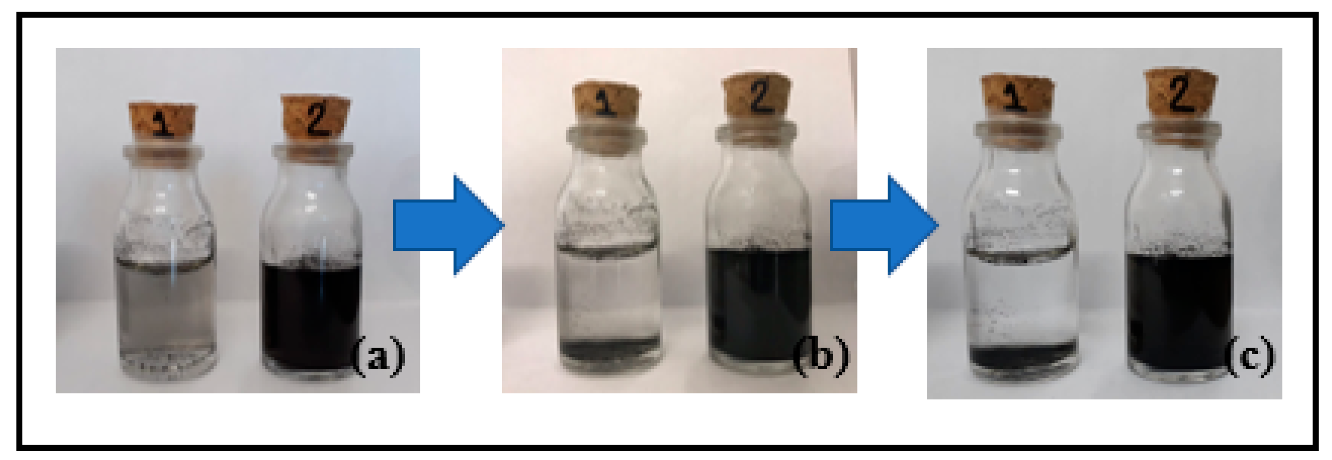
3.1. Dispersion Stability of CNT and CNTf in Water

The success of nanofiller functionalization can be estimated by visual analysis of water dispersion stability [34]. For this analysis, CNT and CNTf were placed into two different flasks containing distilled water and dispersed using an ultrasonic bath. The flasks were kept at rest and photographed at specific time intervals. This method cannot determine the absolute quality of dispersion, but it is useful for comparative studies, where the samples were compared under identical conditions.
The comparison between dispersion stability of non-functionalized CNT (Flask 1) and functionalized CNT, CNTf (Flask 2) is shown in Figure 1, in which the flasks were photographed 24 h (Figure 1a), 1 week (Figure 1b) and 3 weeks (Figure 1c) after dispersion in an ultrasonic bath.
The dispersion quality of CNT has associated with the degree of bundles occurrence over time. Figure 1 shows that the functionalized CNT (Flask 2) demonstrated greater dispersion and few agglomerations over time. After 24 h, the non-functionalized CNT (Flask 1) had agglomerates at the bottom and on the surface of the flask, due to its hydrophobic character and low ability to form hydrogen bonds [52]. In Figure 1b, after 1 week the dispersion was more stable and most of the CNT had settled in the bottom of the flask due to their high surface energy and lack of chemical affinity with the dispersing medium [53].
As shown in Figure 1c, after 3 weeks it can be observed an increase in CNT agglomeration. While functionalization allowed the dispersion becomes more stable. According to Montanheiro et al. [34] when a surface is subjected to functionalization reactions, functional groups are formed, and they can be positively or negatively charged. The presence of the same-sign electrostatic charges on the CNT surface makes them repel one another, maintaining the dispersed material. The insertion of oxygen-containing groups in the CNT, introduced by the chemical oxidative process, caused an optimization of dispersion stability which is explained by the formation of negative charges, therefore creates the electrostatic stability required for a colloidal suspension [54]. Moreover, hydrogen bonds between these functional groups present in the walls of nanotubes and water molecules.

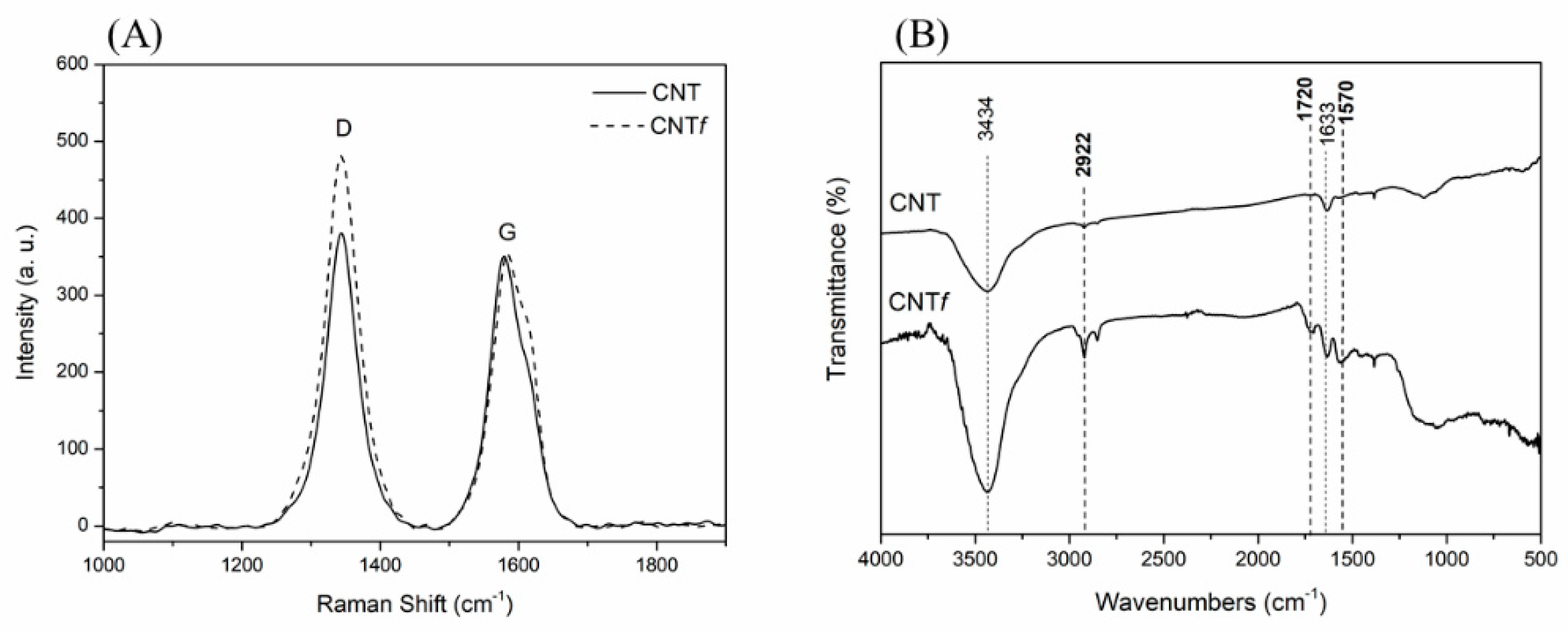
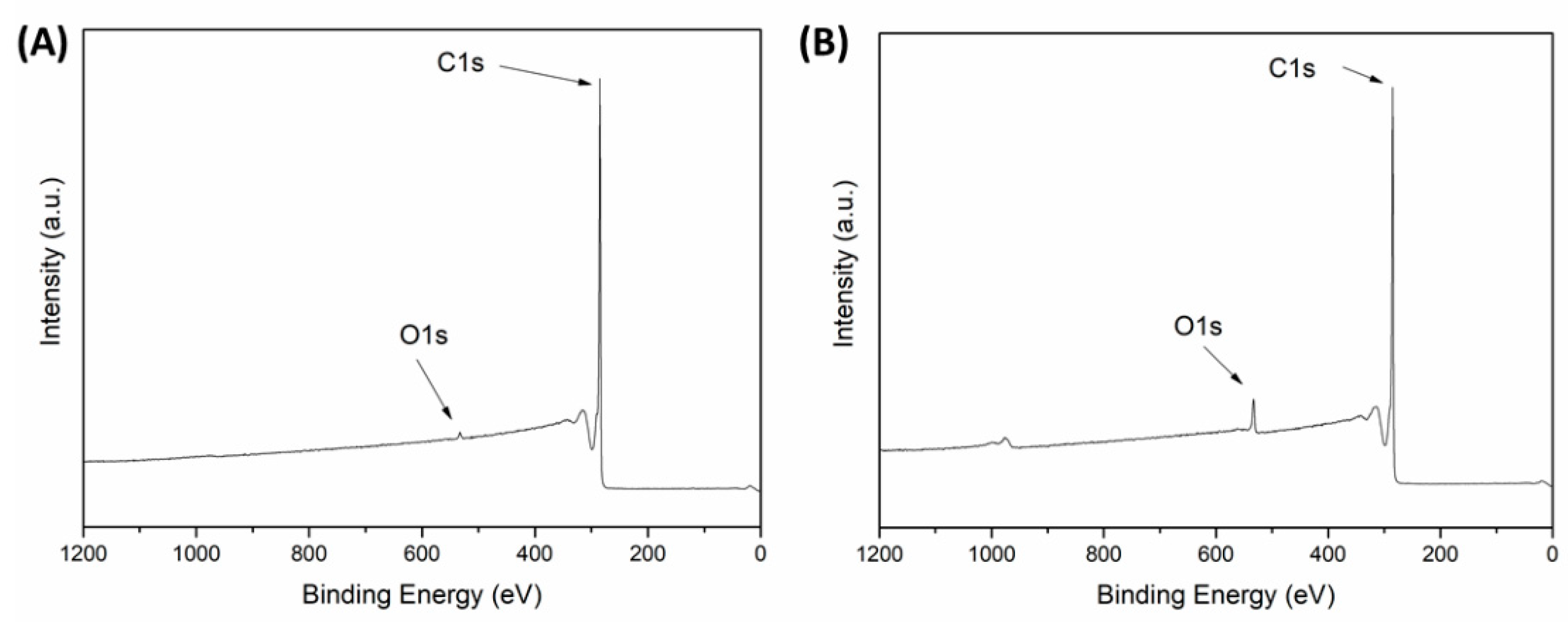
3.2. Structural Analysis

Raman spectroscopy is widely used to characterize materials such as carbon nanotubes, as it provides information about the degree of disorder in the crystal lattice. CNT is not free of defects; inevitably it has defects from its production, which may influence its physicochemical properties. Among the intrinsic defects in carbon nanotubes may include twists, defective rings along nanotube walls, and vacancies [55].
Figure 2A shows the Raman spectra for CNT and CNTf. Both spectra present two bands: the band at 1343 cm−1 represents the D band, which is attributed to the defects and disorders present in the graphitic structure of the CNT and the G band at 1580 cm−1, tangential shear mode due to elongation in the graphitic plane. The G band occurs between 1400 and 1650 cm−1, provides information about the metallic or semiconductor character of the carbon nanotubes, depending on their chirality, and the D band is the mode coming from structural disorder and only arises due to nanotube translational symmetry breaking, which may be caused by the presence of a defect or a bond with some molecule [56].
The greater the number of defects, the greater the intensity of the D band. The density of defects and disordered structures present in the structure of the CNT and CNTf can be analyzed by the ratio between the intensities of the D and G peaks (ID/IG), which give information about the degree of functionalization of the CNT [57]. The ID/IG values for CNT and CNTf are 1.08 and 1.31, respectively, indicating that the functionalization process induces an increase in D band intensity. This result may be related to the oxidation of amorphous carbon on the surface of the CNT, showing that the acid treatment created more defects on its structure.
Moreover, FTIR analysis was used to identify functional groups on the CNT surface. Figure 2B shows FTIR spectra for CNT and CNTf. In both spectra, there is the presence of broadband at 3434 cm−1, which refers to the OH stretching of carboxylic groups (O=C-OH and C-OH). These carboxylic groups present on the CNT surface may be related to the technique employed in sample preparation, as KBr pellets absorb moisture easily, resulting in the detection of OH groups in the spectrum.
Using a strong oxidizer, such as nitric acid, in chemical functionalization, the CNT ends possibly opened and carboxylic groups were introduced at their open ends and their defect sites. The appearance of two new peaks at 1720 cm−1 and 1570 cm-1 in the CNTf sample refer to the carbonyl group stretching mode (C=O) and the carboxylate anion stretching mode, respectively [58,59]. This indicates that functional groups were formed during acid oxidation on carbon atoms on the surface of the CNT, thus confirming the functionalization of the CNT. The appearance of these new bands in the FTIR spectrum corroborate and justify the stability of the dispersion of CNTf in aqueous medium.
Figure 3 shows the XPS survey spectra for CNT and CNTf, which shows two noticeable peaks: one high intensity peak at 286 eV due to carbon (C1s), and other low intensity peak at 534 eV due to oxygen (O1s). After functionalization, the O1s peak increased indicating the presence of oxygen groups. The total oxygen concentration in the CNTf was 4.58%, while the amount of oxygen in CNT before oxidation was 0.96%.

3.3. Characterization of the Nanocomposites

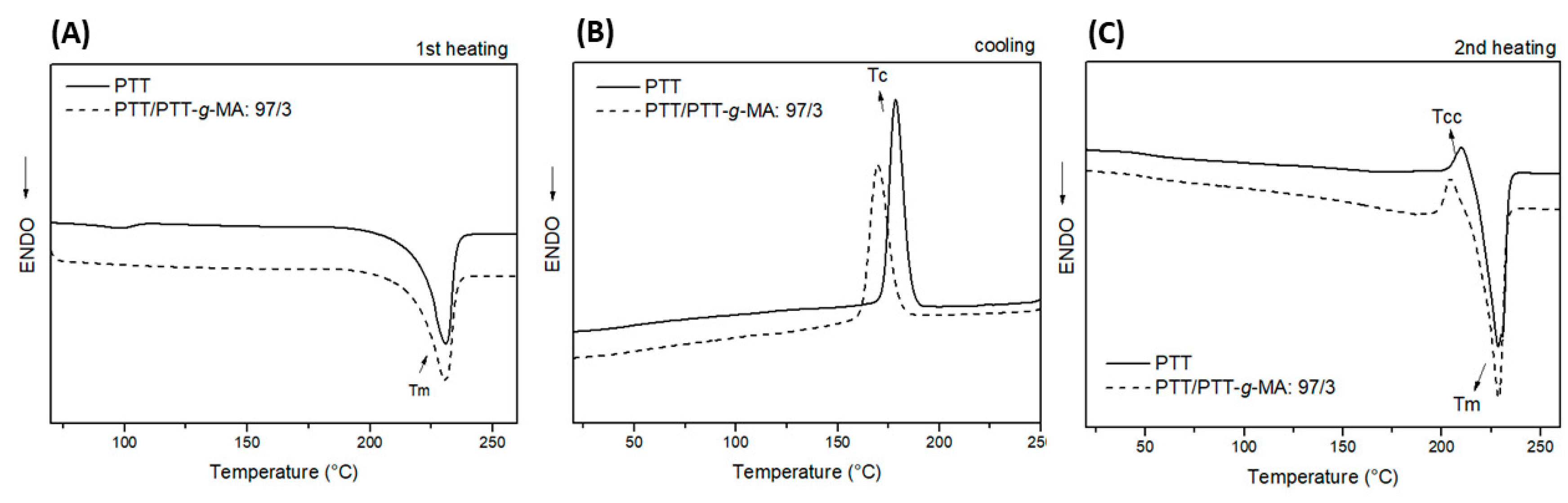
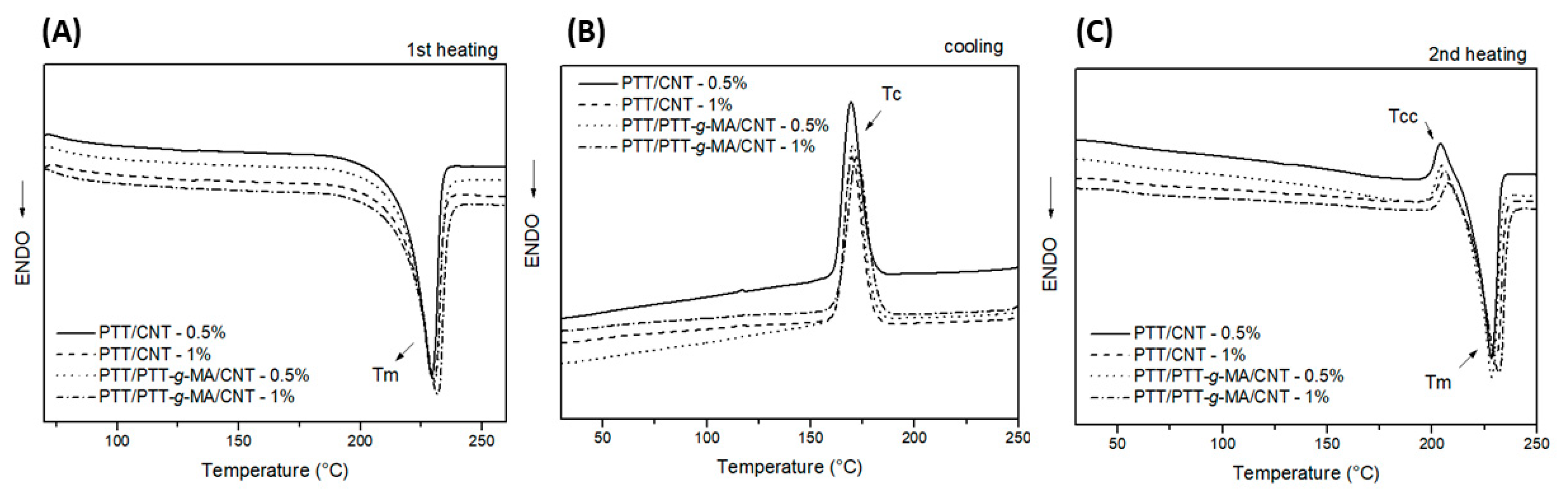
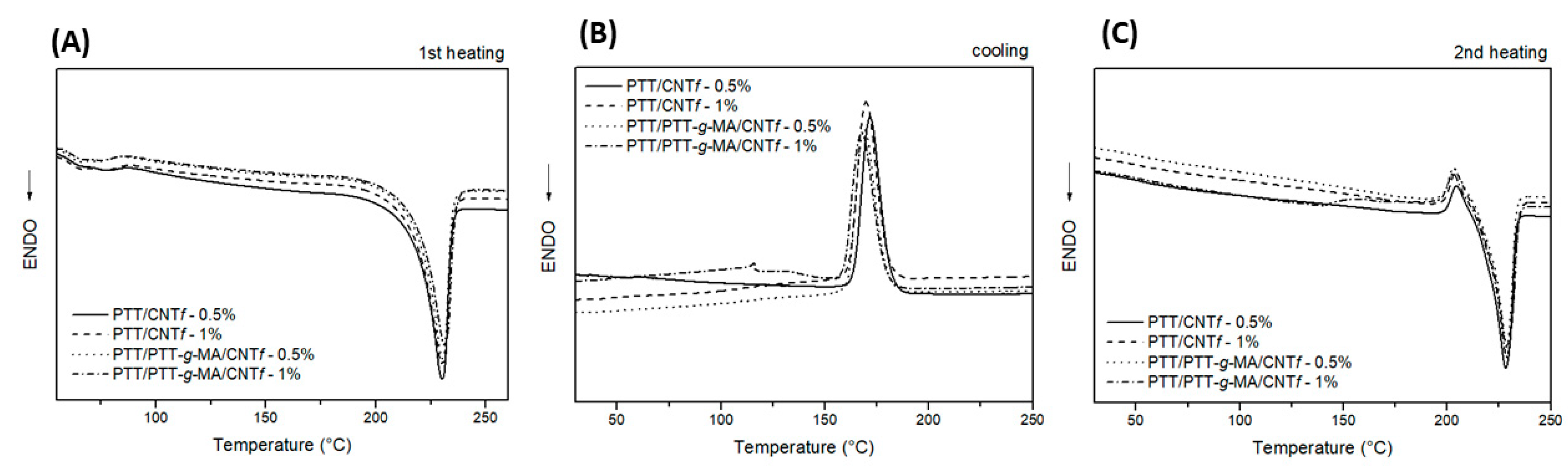
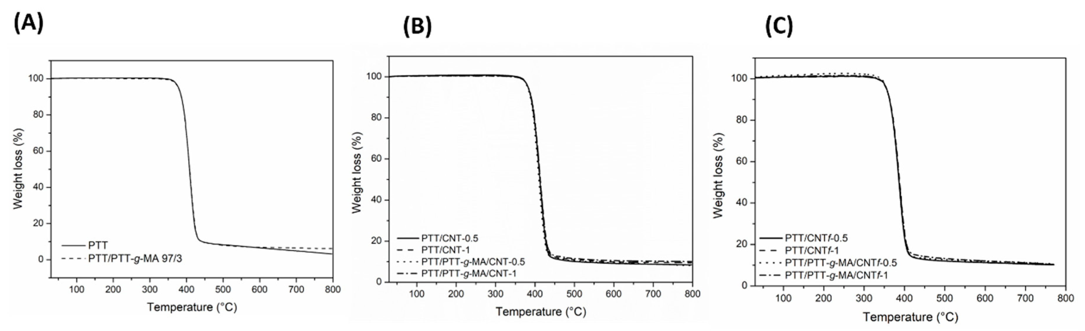
3.3.1. Thermal Analysis: DSC and TGA

Thermal properties and crystallization behavior of PTT and nanocomposites were evaluated by DSC. Figure 4 shows the DSC curves for first heating, cooling and second heating (Figure 4A–C, respectively) for neat PTT and PTT/PTT-g-MA 97/3. The parameters obtained from this analysis for all samples are summarized in Table 2.
From the endothermic peaks from heating scans, it was possible to obtain the melting temperature (Tm) for the materials. PTT has Tm at 229 °C, the addition of PTT-g-MA in PTT did not change the Tm, as observed in Figure 4A,C. The high Tm can be explained by the presence of polar groups in the polymer chains. Such groups form intermolecular bonds that need higher temperatures to break down and enable the mobility of the chains [27].
The crystallization temperature (Tc) was obtained from the exothermic peak in the cooling scan. Tc for PTT is 178 °C and the addition of PTT-g-MA decreased the Tc to 170 °C, probably because maleic anhydride did not act as a nucleating agent for PTT matrix.
In DSC analysis the heating-cooling-heating process is important to eliminate thermal history from the sample. As observed in Figure 4C, the samples showed a cold crystallization temperature (Tcc) in the second heating scan. Cold crystallization is an exothermic crystallization process occurred before the melting and it takes place when the sample is cooled rapidly and has no time to crystallize during the cooling phase [60]. PET, from PTT’s family, also shows cold crystallization phenomenon before melting, as reported in many works in literature [61,62,63].
The crystallinity degree for polymeric samples is influenced by the cooling rate during the solidification. In the crystallization process during the cooling of the samples, the disordered polymer chains in melting are once again configured in an orderly way. The Xc for PTT is 34% and when it is added PTT-g-MA (sample PTT/PTT-g-MA 97/3) the Xc decrease slightly for 32.1%. The graft reaction caused a slight decrease in the degree of crystallinity as the insertion of lateral groups in the PTT chain makes the crystalline reconfiguration of the material more difficult [51].
The effects of CNT and CNTf on thermal properties of PTT, analyzed by DSC are shown in Figure 5 and Figure 6, respectively. The addition of CNT or CNTf did not alter the Tm for PTT, which was kept around 229 °C. These results are important to guarantee that the addition of nanofiller did not change the parameters for processing the nanocomposites during the extrusion process.
Analyzing Table 2, the crystallinity degree had no significant increase with the addition of CNT or CNTf in PTT matrix, this behavior may occur due to the confinement effect of polymeric chains induced by the presence of CNT [35].
Thermogravimetric analysis (TGA) was used to evaluate the influence of the addition of compatibilizer agent, CNT, and CNTf on the thermal degradation behavior of the PTT. Figure 7 shows TGA curves for PTT and PTT/PTT-g-MA 97/3, also in Table 2 is summarized the initial decomposition temperature (Tonset) for all the samples studied.
It is possible to observe that the curves presented one-step of thermal decomposition. The parameters obtained for PTT and PTT/PTT-g-MA 97/3, show that the addition of 3 wt% of the compatibilizer agent did not affect the thermal decomposition pattern of PTT. Moreover, the addition of CNT or CNTf did not alter the PTT thermal decomposition parameters.

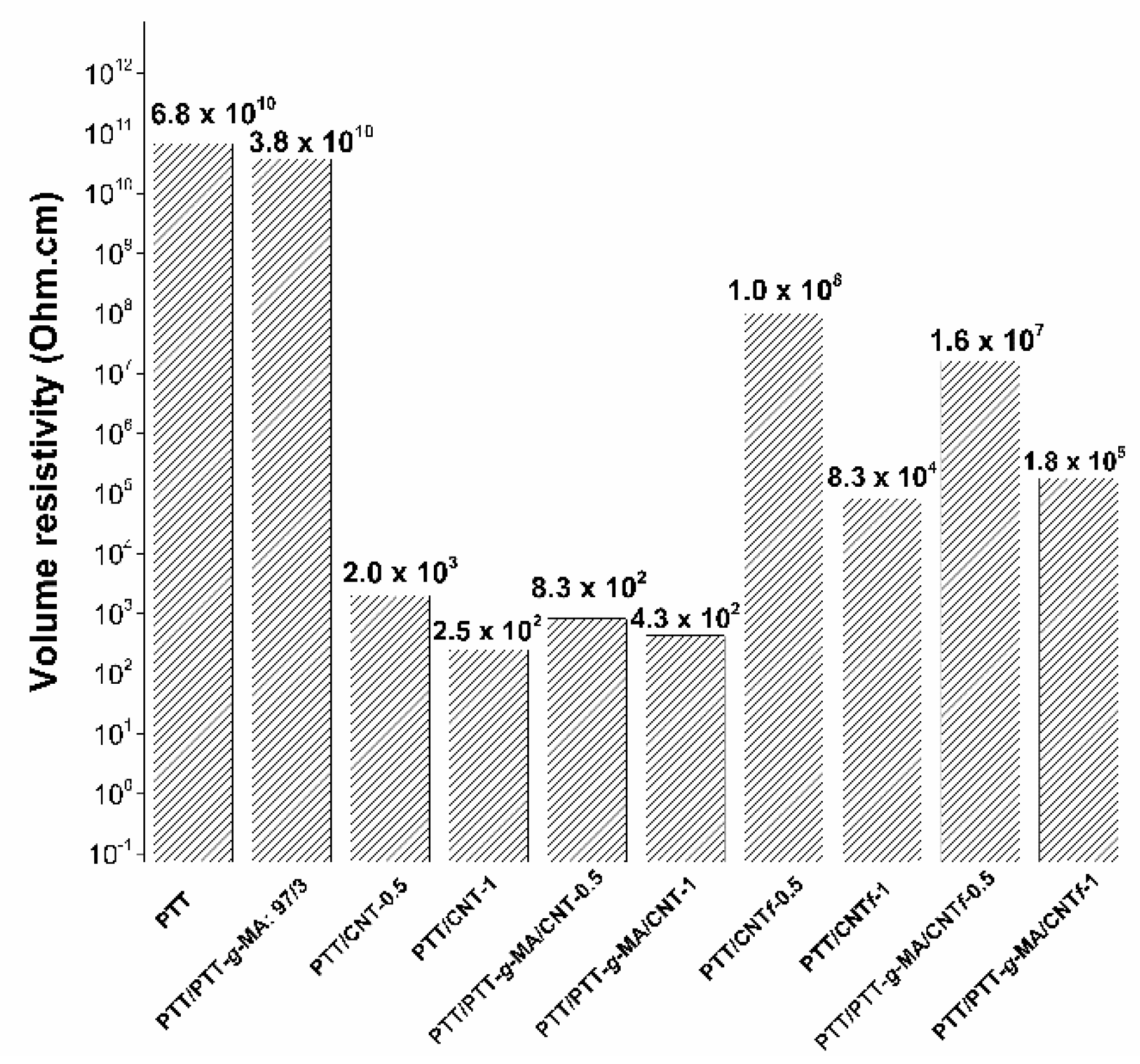
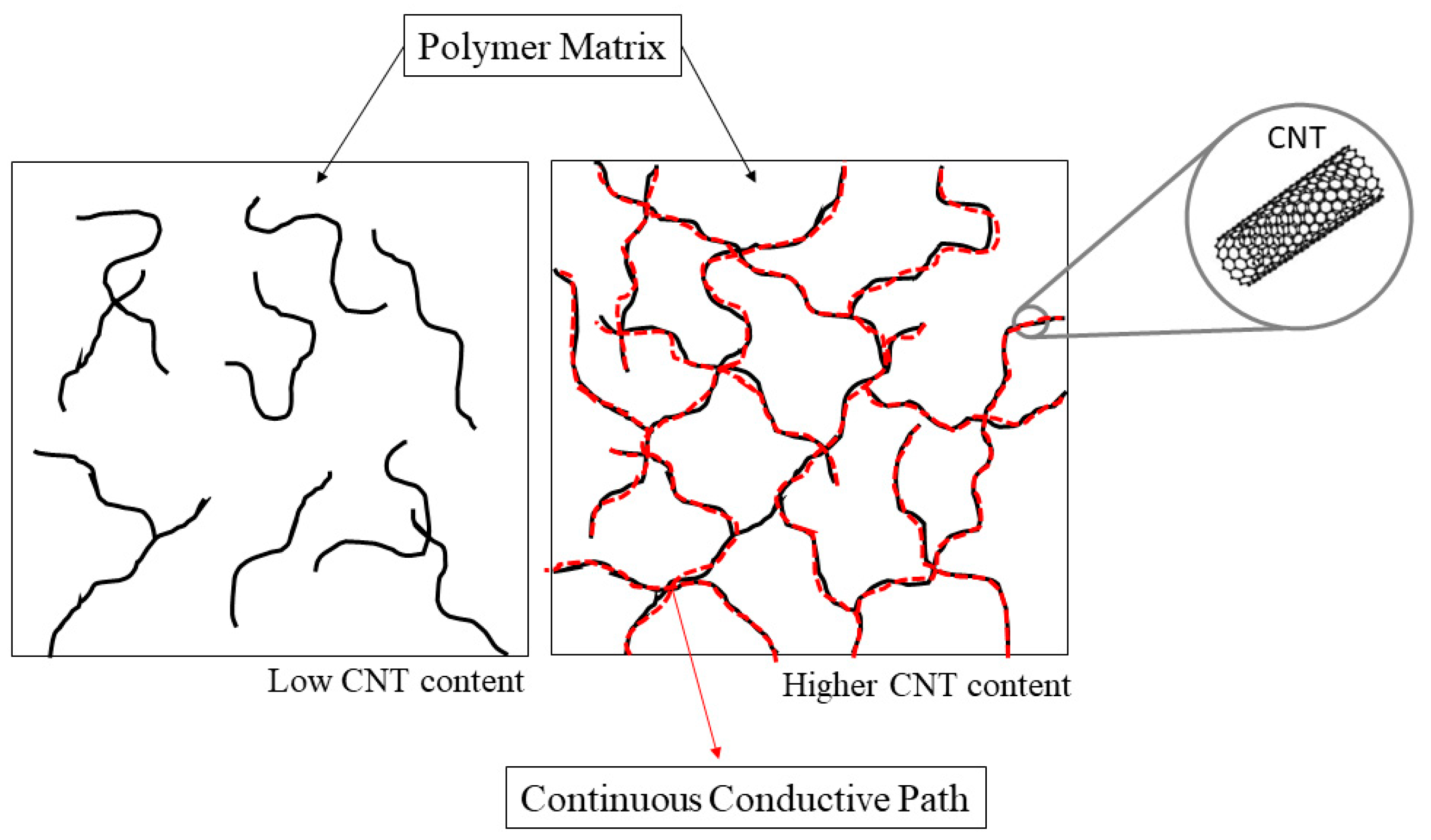
3.3.2. Electrical Properties

The electrical conductivity of PTT and its nanocomposites with CNT and CNTf are shown in Figure 8, in terms of volume resistivity (Ω∙cm). As an insulating polymer, PTT exhibits high electrical resistivity 6.8 × 10¹⁰ Ω∙cm. The addition of 3 wt% of compatibilizer agent was not a significant factor to change the electrical resistivity, compared to PTT, since both samples presented electrical resistivity in order of 1010 Ω∙cm.
Adding CNT on polymer matrices reduces the electrical resistivity and makes them an extrinsic conductor since CNT is known to be an extremely high electrical conductor (~18,000 S/cm) [64,65]. Here, the addition of a relatively small quantity (0.5 wt %) of CNT (sample PTT/CNT-0.5%) decreased the electrical resistivity of the polymer by seven orders of magnitude, approaching 2.0 × 10³ Ω∙cm. Increasing CNT concentration of to 1 wt%, the electrical resistivity decreased eight orders of magnitude, approaching 2.5 × 10² Ω∙cm. The addition of 0.5 or 1 wt% of CNT in the system containing the compatibilizer agent also presented electrical resistivity in order of 102 Ω∙cm (samples PTT/PTT-g-MA/CNT-0.5 and PTT/PTT-g-MA/CNT-1). According to H. Pang et al. [66] electrostatic dissipative materials are in the range of 106 to 1011 Ω∙cm, and conductive materials are in the range of 10 to 106 Ω∙cm, so all the nanocomposites with CNT are in conductive range. This behavior is due to the formation of extra conductive pathways within CNT and the polymer matrix. This continuous connection network is responsible for electron transference in the nanocomposite. Also, the high aspect ratio is important to form these conductivity pathway networks, which probably remained unchanged after the extrusion process. The content of CNT used in this work is higher than the percolation threshold that is the minimum volume fraction which leads to a sharp drop in electrical resistivity.
When the content of CNT in nanocomposite is below the percolation threshold, it means that CNT concentration is low with the large separation distance between them. However, when CNT is enough to reduce their separation distance, some adjacent CNT may be electrically connected resulting in a conductivity pathway network [67]. This mechanism can be better understood by observing the scheme in Figure 9.
Regarding nanocomposites with CNTf, according to Pang´s range [66], there are both electrostatic dissipative (PTT/CNTf-0.5 and PTT/PTT-g-MA/CNTf-0.5, with electrical resistivity in order of 108 and 107 Ω∙cm, respectively) and conductive materials (PTT/CNTf-1 and PTT/PTT-g-MA/CNTf-1, with electrical resistivity in order of 104 and 105 Ω∙cm, respectively). The reduction in electrical conductivity, consequently, increase in resistivity, in all nanocomposites containing CNTf can be explained because when CNT is oxidized there is some destruction of the graphitic conductive structure [68] caused by strong acids used in functionalization.
Thus, it can be observed that the functionalization of CNT greatly affects the electrical resistivity of nanocomposites. However, to produce antistatic packaging with functionalized CNT it is possible to use all the nanocomposites, both in electrostatic dissipative and conductive range, which can guarantee ESD protection.

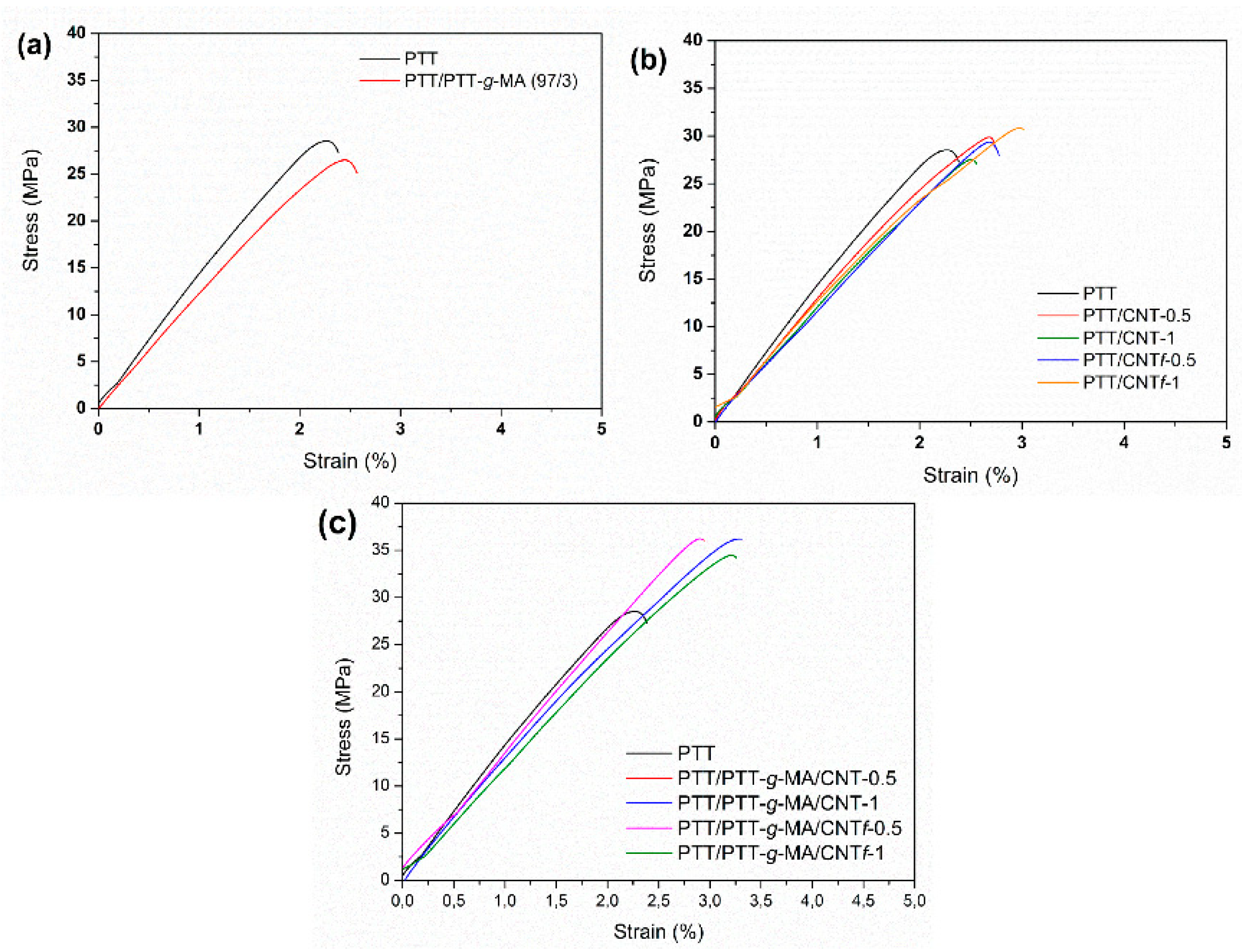
3.3.3. Mechanical Properties

Figure 10 shows the stress-strain curves for the samples and Table 3 shows the values of the ultimate tensile strength (UTS), elongation at break (εr) and Young’s modulus (E) for the compositions. It can be noted that the addition of the compatibilizer agent decreases the UTS and E compared to neat PTT. This behavior can be explained because the compatibilizer agent prepared by reactive processing has a lower viscosity than extruded PTT, this fact is indicative of breakage of polymer chains [39]. Thus, adding small amounts of PTT-g-MA into PTT can auxiliary for a small reduction in the parameters analyzed. A small reduction in the elastic modulus of this material contributed to a small increase in deformation at break.
The addition of 0.5 wt% of CNT had not a great influence on mechanical properties compared to neat PTT. However, the addition of 1 wt% of CNT decreased Young´s modulus from 1433 MPa in PTT to 1195 MPa in PTT/CNT (99/1), which can indicate low adhesion of CNT in a polymeric matrix and probably CNT are not so dispersed in PTT matrix.
When CNTf is added in PTT, the tensile strength increased from 29 MPa in neat PTT to 32 MPa in PTT/CNTf (99/1), indicating that functionalization of CNT is a necessary stage to improve the adhesion and dispersion of the nanofiller in a matrix, improving the mechanical properties of the nanocomposite.
The nanocomposites with PTT/PTT-g-MA matrix presented very satisfactory results. All compatible nanocomposites showed tensile strength much higher than PTT or PTT/CNT nanocomposites. The PTT has a fragile fracture and the addition of CNT and compatibilizer agent, besides increasing the tensile strength, helped to increase the deformation at the break when compared to PTT. The elastic modulus of the compositions is relatively close, considering the standard deviations.

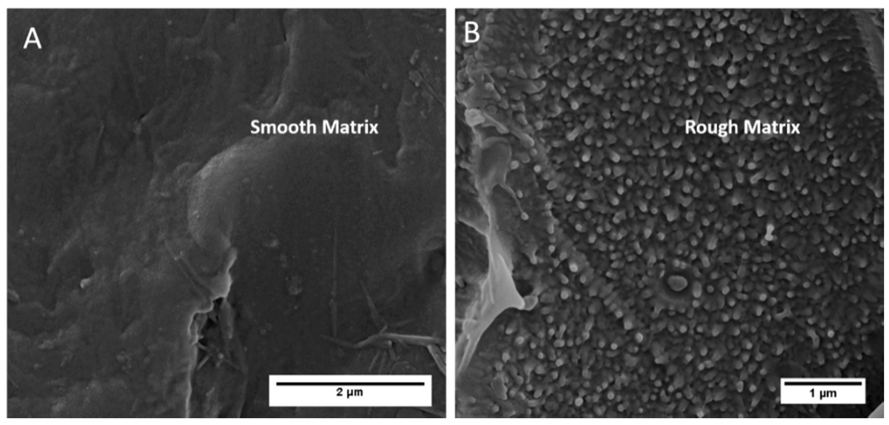
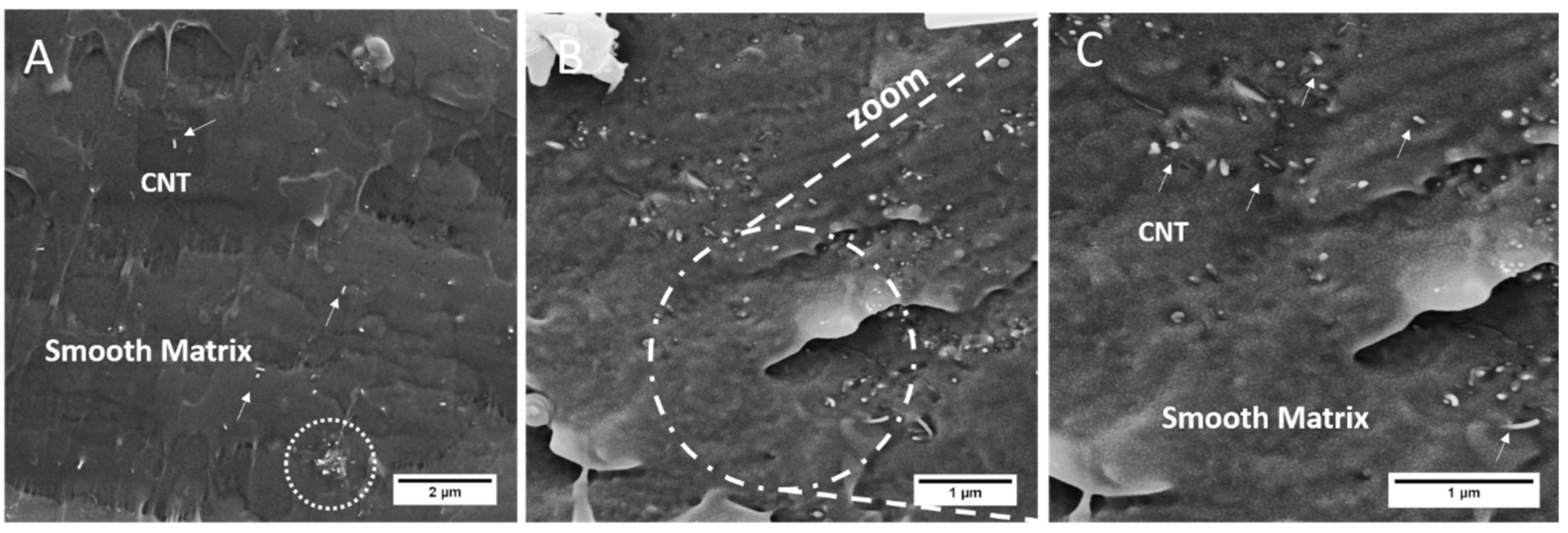
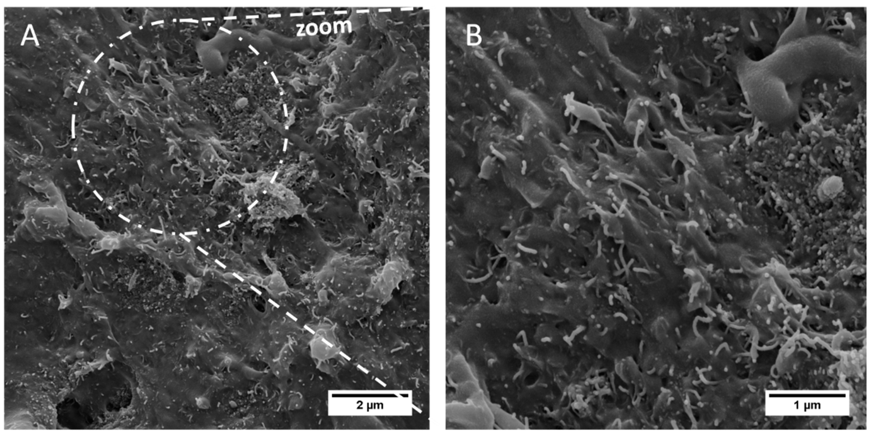
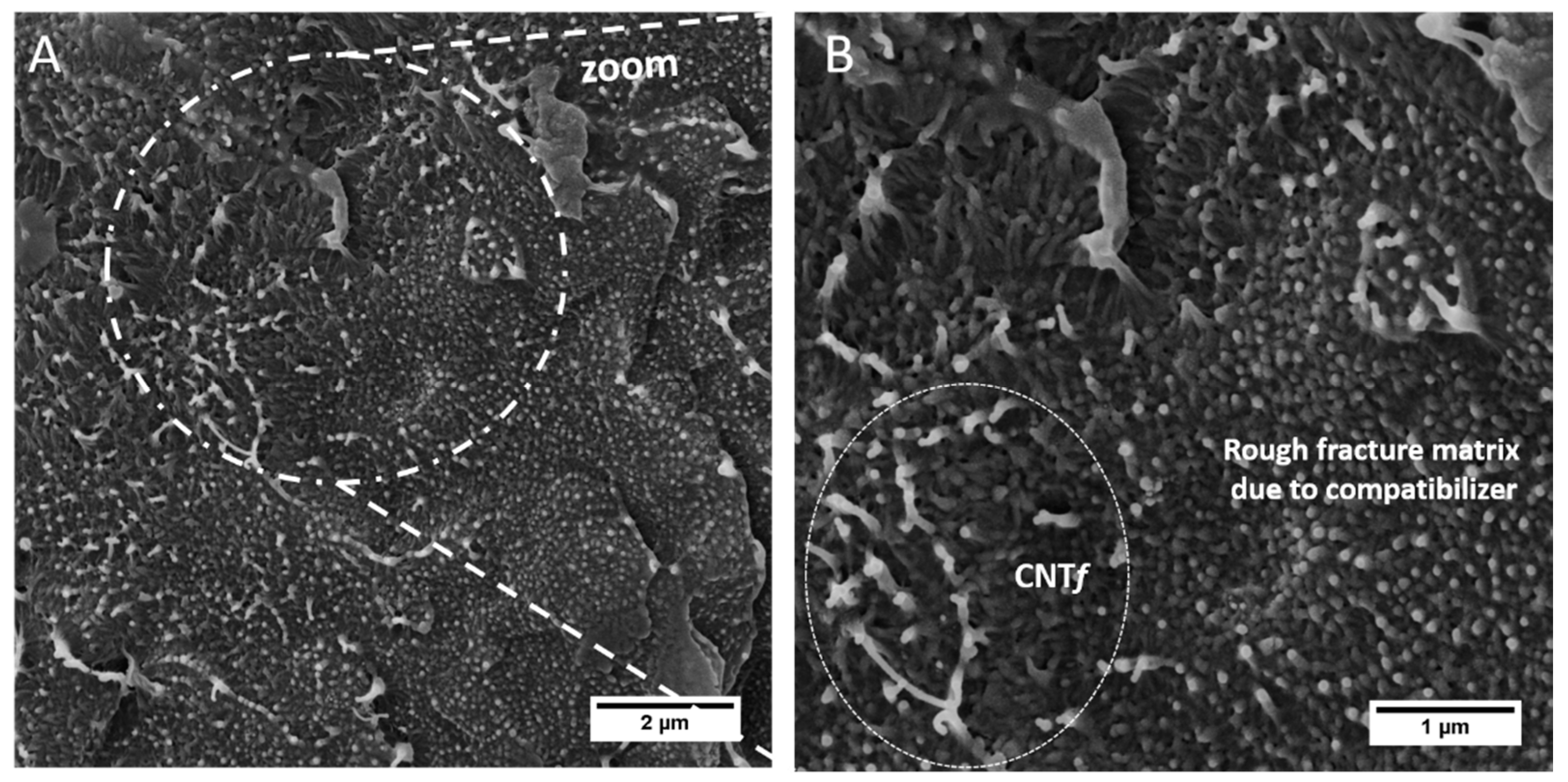
3.3.4. Morphology Characteristics

The SEM-FEG images of the PTT and the nanocomposites allowed the observation of morphological changes on PTT generated by the addition of compatibilizer agent and/or CNT. Additionally, this analysis is also useful to verify the dispersion of CNT in the polymeric matrix and to analyze the influence of its chemical surface treatment on its interaction with the polymeric matrix.
Figure 11A,B show the micrograph of PTT and PTT/PTT-g-MA 97/3, respectively. The PTT polymer shows a smooth fracture surface. It is noted that the addition of the compatibilizer agent modified the PTT fracture mechanism. When PTT-g-MA is added in PTT, many irregularities are observed on the surface, characterizing a rough matrix, caused possibly due to maleic anhydride from PTT-g-MA.
Figure 12 compares the nanocomposites with CNT and CNTf without compatibilizer agent. It is possible to note that CNT functionalized improves the interfacial adhesion with the PTT polymer matrix, indicated by the arrows in Figure 12. This good interface indicates good interaction between nanofiller and polymer matrix. This interaction is not so efficient on unmodified CNT, notably due to the lack of nanofiller impregnation on the polymeric matrix. Moreover, there is a region in the dashed area circled in Figure 12A, indicating agglomeration of CNT in the polymer matrix.
Figure 13 shows the micrography of the nanocomposites with 0.5 wt% of CNT with the compatibilizer agent. There is a difference in the polymer matrix morphology, due to the compatibilizer agent and its interface with CNT is strong.
Figure 14 shows the micrography for the sample PTT/PTT-g-MA/CNTf -0.5 and it is possible to observe a good interface between CNTf and the modified rough matrix PTT-g-MA. The preparation of the compatibilizer agent has the intention to avoid CNT agglomeration and optimizing its dispersion and distribution in a polymer matrix.
Although the CNT functionalization mainly changes the electrical properties and morphological characteristics of the PTT matrix in the nanocomposites, it is important for the improvement of the dispersion of CNT in the PTT matrix, and, at the same time, it can achieve the required characteristics to use in antistatic packaging.

4. Conclusions

The effect of chemical functionalization of carbon nanotubes and the addition of a compatibilizer agent (PTT-g-MA) on thermal, mechanical, electrical, and morphological properties of PTT/CNT nanocomposites were evaluated.
Stability dispersion in water showed that functionalization improved the dispersion of CNT due to an increase in the number of polar interactions performed by the functional groups. Also, Raman spectroscopy revealed defects in the CNT structure due to its functionalization. Moreover, FTIR showed the appearance of two new bands related to creation of functional groups inserted on CNT surface after functionalization.
DSC analysis showed that the CNT or CNTf did not act as a nucleation agent but generated a confinement effect of the polymeric chains since no significant increase in PTT crystallinity degree was observed after the insertion of CNT or CNTf.
For the mechanical properties it was observed that, compared to neat PTT, the addition of PTT-g-MA generated a reduction of the maximum tension and elastic modulus due to the modifications caused in the polymeric matrix, such as a rough fracture, observed by SEM-FEG. Morphological analysis also showed that PTT-g-MA and CNTf were fundamental for the formation of a good interface between polymer matrix and functional filler. Tensile test results conclude that the combination of compatibilizer agent and CNTf contributed to an improvement in the mechanical properties of the nanocomposite.
Electrical analysis showed that the addition of 0.5 or 1 wt% of CNT decreased considerably the electrical resistivity of PTT, reaching the conductive materials range. The nanocomposites prepared with 1 wt% of CNTf also presented electrical resistivity in the range of conductive materials. On the other hand, nanocomposites with 0.5 or 1wt% of CNTf reached electrical resistivity in order of 107 or 108 Ω∙cm, being, thus, in the electrostatic materials range, for antistatic applications. Even though these results indicated that antistatic packages based on PTT matrix can be prepared using CNT with or without functionalization, very low amounts (0.1 or 0.3 wt%) of unmodified CNTs might also lead to the required decrease in resistivity to be in the antistatic materials range and might also lead to a reinforcement of the PTT. So, these composites (PTT/CNT-0.1, PTT/CNT-0.3, PTT/PTT-g-MA/CNT-0.1 and PTT/PTT-g-MA/CNT-0.3) can be the topic of comparison in further investigations.

Author Contributions

Conceptualization, N.F.B., H.M.Z., L.S.M. and F.R.P.; Data curation, N.F.B., H.M.Z., L.S.M. and F.R.P.; Formal analysis, N.F.B., L.S.M. and F.R.P.; Funding acquisition, F.R.P.; Methodology, N.F.B., H.M.Z. and F.R.P.; Resources, H.M.Z. and F.R.P.; Supervision, L.S.M. and F.R.P.; Validation, F.R.P.; Visualization, L.S.M.; Writing—original draft, N.F.B. and H.M.Z.; Writing—review & editing, L.S.M. and F.R.P. All authors have read and agreed to the published version of the manuscript.

Funding

This study was financed in part by the Coordenação de Aperfeiçoamento de Pessoal de Nível Superior - Brasil (CAPES) - Finance Code 001. The authors are grateful to Conselho Nacional de Desenvolvimento Científico e Tecnológico (CNPq - process number 405675/2018-6) and Fundação de Amparo à Pesquisa do Estado de São Paulo (FAPESP process number 2018/05415-8).

Acknowledgments

We would like to thank the Laboratório de Cerâmicas Avançadas (LCA – UNIFESP) for impedance tests for electrical conductivity, the Instituto de Tecnologia Aeronáutica (ITA) for Raman and FTIR analysis, the Instituto Nacional de Pesquisas Espaciais (INPE) for SEM-FEG analysis and Laboratório Nacional de Nanotecnologia (LLNano) for XPS analysis.

Conflicts of Interest

The authors declare that they have no conflict of interest.

References

  1. Dahman, S.J. All Polymeric Compounds: Conductive and Dissipative Polymers in ESD Control Materials. In Proceedings of the Electrical Overstress/Electrostatic Discharge Symposium Proceedings, Las Vegas, NV, USA, 21–25 Septemeber 2003; pp. 1–7. [Google Scholar]
  2. Dahman, S.J.; Avlyanov, J. The Use of Conducting Polymer Composites in Thermoplastics for Tuning Surface Resistivity. In Conductive Polymers and Plastics; William Andrew Publishing: Norwich, NY, USA, 1999; pp. 225–230. [Google Scholar]
  3. Chen, C.H.; Li, H.C.; Teng, C.C.; Yang, C.H. Fusion, electrical conductivity, thermal, and mechanical properties of rigid poly(vinyl chloride) PVC/carbon black (CB) composites. J. Appl. Polym. Sci. 2006, 99, 2167–2173. [Google Scholar] [CrossRef]
  4. Santos, M.S.D.; Montagna, L.S.; Rezende, M.C.; Passador, F.R. A new use for glassy carbon: Development of LDPE/glassy carbon composites for antistatic packaging applications. J. Appl. Polym. Sci. 2019, 136, 47204. [Google Scholar] [CrossRef]
  5. Tian, Y.; Zhang, X.; Geng, H.Z.; Yang, H.J.; Li, C.; Da, S.X.; Lu, X.; Wang, J.; Jia, S.L. Carbon nanotube/polyurethane films with high transparency, low sheet resistance and strong adhesion for antistatic application. RSC Adv. 2017, 7, 53018–53024. [Google Scholar] [CrossRef] [Green Version]
  6. da Silva, T.F.; Menezes, F.; Montagna, L.S.; Lemes, A.P.; Passador, F.R. Preparation and characterization of antistatic packaging for electronic components based on poly(lactic acid)/carbon black composites. J. Appl. Polym. Sci. 2019, 136, 47273. [Google Scholar] [CrossRef]
  7. Silva, L.N.; dos Anjos, E.G.R.; Morgado, G.F.d.M.; Marini, J.; Backes, E.H.; Montagna, L.S.; Passador, F.R. Development of antistatic packaging of polyamide 6/linear low-density polyethylene blends-based carbon black composites. Polym. Bull. 2019, 1–21. [Google Scholar] [CrossRef]
  8. de Miranda, L.F.; Munhoz, A.H., Jr.; Masson, T.J.; de Andrade e Silva, L.G.; Friehe, K. Characterization of antistatic packaging based on PET/rGO. In Characterization of Minerals, Metals, and Materials; Springer International Publishing: Basel, Switzerland, 2019; pp. 523–534. [Google Scholar]
  9. Liang, H.; Xie, F.; Liu, H.; Xie, G. Study on antistatic PET/PTT-CNTs composites. Appl. Mech. Mater. 2012, 217, 75–78. [Google Scholar]
  10. Braga, N.F.; LaChance, A.M.; Liu, B.; Sun, L.; Passador, F.R. Influence of compatibilizer and carbon nanotubes on mechanical, electrical, and barrier properties of PTT/ABS blends. Adv. Ind. Eng. Polym. Res. 2019, 2, 121–125. [Google Scholar] [CrossRef]
  11. Run, M.; Song, A.; Wang, Y.; Yao, C. Melting, Crystallization Behaviors, and Nonisothermal Crystallization Kinetics of PET/PTT/PBT Ternary Blends. J. Appl. Polym. Sci. 2007, 104, 3459–3468. [Google Scholar] [CrossRef]
  12. Chung, W.-T.; Yeh, W.-J.; Hong, P.-D. Melting Behavior of Poly (trimethylene terephthalate). J. Appl. Polym. Sci. 2002, 83, 2426–2433. [Google Scholar] [CrossRef]
  13. Supaphol, P.; Dangseeyun, N.; Thanomkiat, P.; Nithitanakul, M. Thermal, Crystallization, Mechanical, and Rheological Characteristics of Poly(trimethylene terephthalate)/Poly(ethylene terephthalate) Blends. J. Polym. Sci. Part B Polym. Phys. 2004, 42, 676–686. [Google Scholar] [CrossRef]
  14. Run, M.; Li, X.; Song, H.; Wang, Z. Studies on the morphological, rheological, electrical, mechanical and thermal properties of the PTT/SCF composites. J. Thermoplast. Compos. Mater. 2010, 23, 765–777. [Google Scholar] [CrossRef]
  15. Wang, L.; Zhao, H.F.; Lin, J.X. Studies on the ultrasonic-assisted dyeing of poly(trimethylene terephthalate) fabric. Coloration Technol. 2010, 126, 243–248. [Google Scholar] [CrossRef]
  16. Lyoo, W.S.; Lee, H.S.; Ji, B.C.; Han, S.S.; Koo, K.; Kim, S.S.; Kim, J.H.; Lee, J.S.; Son, T.W.; Yoon, W.S. Effect of zone drawing on the structure and properties of melt-spun poly(trimethylene terephthalate) fiber. J. Appl. Polym. Sci. 2001, 81, 3471–3480. [Google Scholar] [CrossRef]
  17. Cho, J.W.; Woo, K.S. Aging and cold crystallization of melt-extruded poly(trimethylene terephthalate) films. J. Polym. Sci. Part B Polym. Phys. 2001, 39, 1920–1927. [Google Scholar] [CrossRef]
  18. Zhang, J. Study of Poly (trimethylene terephthalate) as an Engineering Thermoplastics Material. J. Appl. Polym. Sci. 2004, 91, 1657–1666. [Google Scholar] [CrossRef]
  19. Bigg, D.M. Mechanical and conductive properties of metal fibre-filled polymer composites. Composites 1979, 10, 95–100. [Google Scholar] [CrossRef]
  20. Narkis, M.; Zilberman, M.; Siegmann, A. On the “curiosity” of electrically conductive melt processed doped-polyaniline/polymer blends versus carbon-black/polymer compounds. Polym. Adv. Technol. 1997, 8, 525–528. [Google Scholar] [CrossRef]
  21. Fournier, J.; Boiteux, G.; Seytre, G. Fractal analysis of the percolation network in epoxy-polypyrrole composites. Phys. Rev. B Condens. Matter Mater. Phys. 1997, 56, 5207–5212. [Google Scholar] [CrossRef]
  22. Choi, H.J.; Kim, M.S.; Ahn, D.; Yeo, S.Y.; Lee, S. Electrical percolation threshold of carbon black in a polymer matrix and its application to antistatic fibre. Sci. Rep. 2019, 9, 6338. [Google Scholar] [CrossRef] [Green Version]
  23. Huang, C.L.; Wu, H.H.; Jeng, Y.C.; Liang, W.Z. Electrospun graphene nanosheet-filled poly(trimethylene terephthalate) composite fibers: Effects of the graphene nanosheet content on morphologies, electrical conductivity, crystallization behavior, and mechanical properties. Polymers 2019, 11, 164. [Google Scholar] [CrossRef] [Green Version]
  24. de Souza, W.O.; Garcia, K.; de Avila Von Dollinger, C.F.; Pardini, L.C. Electrical behavior of carbon fiber/phenolic composite during pyrolysis. Mater. Res. 2015, 18, 1209–1216. [Google Scholar] [CrossRef] [Green Version]
  25. Zhang, W.; Dehghani-Sanij, A.A.; Blackburn, R.S. Carbon based conductive polymer composites. J. Mater. Sci. 2007, 42, 3408–3418. [Google Scholar] [CrossRef]
  26. Gupta, A.; Choudhary, V. Electrical conductivity and shielding effectiveness of poly (trimethylene terephthalate)/multiwalled carbon nanotube composites. J. Mater. Sci. 2011, 46, 6416–6423. [Google Scholar] [CrossRef]
  27. Callister, W.D.; Rethwisch, D.G. Material Science and Engineering: An Introduction; John Wiley: Hoboken, NJ, USA, 2000. [Google Scholar]
  28. Gao, L.; Chou, T.W.; Thostenson, E.T.; Godara, A.; Zhang, Z.; Mezzo, L. Highly conductive polymer composites based on controlled agglomeration of carbon nanotubes. Carbon 2010, 48, 2644–2673. [Google Scholar] [CrossRef]
  29. Pötschke, P.; Fornes, T.D.; Paul, D.R. Rheological behavior of multiwalled carbon nanotube/polycarbonate composites. Polymer 2002, 43, 3247–3255. [Google Scholar] [CrossRef]
  30. Andrews, R.; Jacques, D.; Rao, A.M.; Rantell, T.; Derbyshire, F.; Chen, Y.; Chen, J.; Haddon, R.C. Nanotube composite carbon fibers. Appl. Phys. Lett. 1999, 75, 1329–1331. [Google Scholar] [CrossRef] [Green Version]
  31. Alig, I.; Lellinger, D.; Dudkin, S.M.; Pötschke, P. Conductivity spectroscopy on melt processed polypropylene-multiwalled carbon nanotube composites: Recovery after shear and crystallization. Polymer 2007, 48, 1020–1029. [Google Scholar] [CrossRef]
  32. Atif, R.; Inam, F. Reasons and remedies for the agglomeration of multilayered graphene and carbon nanotubes in polymers. Beilstein J. Nanotechnol. 2016, 7, 1174–1196. [Google Scholar] [CrossRef]
  33. Pan, J.; Bian, L. Influence of agglomeration parameters on carbon nanotube composites. Acta Mech. 2017, 228, 2207–2217. [Google Scholar] [CrossRef]
  34. Montanheiro, T.L.D.A.; Cristóvan, F.H.; Machado, J.P.B.; Tada, D.B.; Durán, N.; Lemes, A.P. Effect of MWCNT functionalization on thermal and electrical properties of PHBV/MWCNT nanocomposites. J. Mater. Res. 2015, 30, 55–65. [Google Scholar] [CrossRef]
  35. Ma, Q.; Cebe, P. Phase structure of electrospun poly(trimethylene terephthalate) composite nanofibers containing carbon nanotubes. J. Therm. Anal. Calorim. 2010, 102, 425–434. [Google Scholar] [CrossRef]
  36. Szymczyk, A.; Roslaniec, Z.; Zenker, M.; García-Gutiérrez, M.C.; Hernández, J.J.; Rueda, D.R.; Nogales, A.; Ezquerra, T.A. Preparation and characterization of nanocomposites based on COOH functionalized multi-walled carbon nanotubes and on poly(trimethylene terephthalate). Express Polym. Lett. 2011, 5, 977–995. [Google Scholar] [CrossRef] [Green Version]
  37. Díez-Pascual, A.M.; Naffakh, M.; Gómez, M.A.; Marco, C.; Ellis, G.; Gonzlez-Domínguez, J.M.; Ansón, A.; Martínez, M.T.; Martínez-Rubi, Y.; Simard, B.; et al. The influence of a compatibilizer on the thermal and dynamic mechanical properties of PEEK/carbon nanotube composites. Nanotechnology 2009, 20, 315707. [Google Scholar] [CrossRef]
  38. Yang, H.S.; Kim, H.J.; Park, H.J.; Lee, B.J.; Hwang, T.S. Effect of compatibilizing agents on rice-husk flour reinforced polypropylene composites. Compos. Struct. 2007, 77, 45–55. [Google Scholar] [CrossRef]
  39. Braga, N.F.; Zaggo, H.M.; Montanheiro, T.L.A.; Passador, F.R. Preparation of Maleic Anhydride Grafted Poly(trimethylene terephthalate) (PTT-g-MA) by Reactive Extrusion Processing. J. Manuf. Mater. Process. 2019, 3, 37. [Google Scholar] [CrossRef] [Green Version]
  40. Kim, H.S.; Kim, S.; Kim, H.J.; Yang, H.S. Thermal properties of bio-flour-filled polyolefin composites with different compatibilizing agent type and content. Thermochim. Acta 2006, 451, 181–188. [Google Scholar] [CrossRef]
  41. Montanheiro, T.L.d.A.; Passador, F.R.; de Oliveira, M.P.; Duran, N.; Lemes, A.P. Preparation and characterization of maleic anhydride grafted poly (hydroxybutirate-CO-hydroxyvalerate)-PHBV-g-MA. Mater. Res. 2016, 19, 229–235. [Google Scholar] [CrossRef] [Green Version]
  42. Wu, C.S.; Liao, H.T. Characterization and antistatic behavior of SiO2-functionalized multiwalled carbon nanotube/poly(trimethylene terephthalate) composites. J. Polym. Res. 2013, 20, 253. [Google Scholar] [CrossRef]
  43. Paszkiewicz, S.; Szymczyk, A.; Sui, X.M.; Wagner, H.D.; Linares, A.; Cirera, A.; Varea, A.; Ezquerra, T.A.; Rosłaniec, Z. Electrical conductivity and transparency of polymer hybrid nanocomposites based on poly(trimethylene terephthalate) containing single walled carbon nanotubes and expanded graphite. J. Appl. Polym. Sci. 2017, 134, 44370–44379. [Google Scholar] [CrossRef] [Green Version]
  44. Ajitha, A.A.; Mohammed Arif, M.P.; Aswathi, M.K.; Mathew, L.P.; Geethamma, G.; Kalarikkal, N.; Thomas, S.; Volova, T. An effective EMI shielding material based on poly(trimethylene terephthalate) blend nanocomposites with multiwalled carbon nanotubes. New J. Chem. 2018, 42, 13915–13926. [Google Scholar]
  45. Gupta, A.; Choudhary, V. Rheologic and mechanical properties of multiwalled carbon nanotubes-reinforced poly(trimethylene terephthalate) composites. J. Mater. Sci. 2013, 48, 3347–3356. [Google Scholar] [CrossRef]
  46. Gupta, A.; Choudhary, V. Effect of multi-walled carbon nanotubes on mechanical and rheological properties of poly(trimethylene terephthalate). J. Mater. Sci. 2014, 49, 3839–3846. [Google Scholar] [CrossRef]
  47. Paszkiewicz, S.; Szymczyk, A.; Kasprowiak, I.; Zenker, M.; Pilawka, R.; Linares, A.; Ezquerra, T.A. Electrical and Rheological Characterization of Poly(Trimethylene Terephthalate) Hybrid Nanocomposites Filled With COOH Functionalized MWCNT and Graphene Nanosheets. Polym. Compos. 2018, 39, 2961–2968. [Google Scholar] [CrossRef]
  48. Wu, C.-S. Synthesis and Characterization of Poly(trimethylene terephthalate) Nanocomposites Incorporating Multi-Walled Carbon Nanotubes. J. Appl. Polym. Sci. 2009, 114, 1633–1642. [Google Scholar] [CrossRef]
  49. Data Sheet: Multiwall carbon nanotubes. Available online: http://www.nanocyl.com/wp-content/uploads/2016/02/DM-Qual-05-MSDS-NC7000-V11.pdf (accessed on 9 February 2016).
  50. Standard Test Method for Tensile Properties of Thin Plastic Sheeting D882-12; ASTM International: West Conshohocken, PA, USA, 2012.
  51. Szymczyk, A.; Paszkiewicz, S.; Roslaniec, Z. Influence of intercalated organoclay on the phase structure and physical properties of PTT-PTMO block copolymers. Polym. Bull. 2013, 70, 1575–1590. [Google Scholar] [CrossRef]
  52. Li, H.; Qiu, Y. Dispersion, sedimentation and aggregation of multiwalled carbon nanotubes as affected by single and binary mixed surfactants. R. Soc. Open Sci. 2019, 6, 190241. [Google Scholar] [CrossRef] [Green Version]
  53. Lee, J.; Kim, M.; Hong, C.K.; Shim, S.E. Measurement of the dispersion stability of pristine and surface-modified multiwalled carbon nanotubes in various nonpolar and polar solvents. Meas. Sci. Technol. 2007, 18, 3707–3712. [Google Scholar] [CrossRef]
  54. Xiao, M.; Zhu, J.; Ge, J.; Liu, C.; Xing, W. The enhanced electrocatalytic activity and stability of supported Pt nanopartciles for methanol electro-oxidation through the optimized oxidation degree of carbon nanotubes. J. Power Sources 2015, 281, 34–43. [Google Scholar] [CrossRef]
  55. Datsyuk, V.; Kalyva, M.; Papagelis, K.; Parthenios, J.; Tasis, D.; Siokou, A.; Kallitsis, I.; Galiotis, C. Chemical oxidation of multiwalled carbon nanotubes. Carbon 2008, 46, 833–840. [Google Scholar] [CrossRef]
  56. de Souza Filho, A.G.; Fagan, S.B. Funcionalização de nanotubos de carbono. Quim. Nova 2007, 30, 1695–1703. [Google Scholar] [CrossRef]
  57. Eswaraiah, V.; Sankaranarayanan, V.; Ramaprabhu, S. Inorganic nanotubes reinforced polyvinylidene fluoride composites as low-cost electromagnetic interference shielding materials. Nanoscale Res. Lett. 2011, 6, 137. [Google Scholar] [CrossRef] [PubMed] [Green Version]
  58. Li, X.; Ji, X.; Qin, A.; He, C. The plasticized spinning and cyclization behaviors of functionalized carbon nanotube/polyacrylonitrile fibers. RSC Adv. 2015, 5, 52226–52234. [Google Scholar] [CrossRef]
  59. Atieh, M.A.; Bakather, O.Y.; Al-Tawbini, B.; Bukhari, A.A.; Abuilaiwi, F.A.; Fettouhi, M.B. Effect of carboxylic functional group functionalized on carbon nanotubes surface on the removal of lead from water. Bioinorg. Chem. Appl. 2010, 2010. [Google Scholar] [CrossRef] [PubMed]
  60. Hammer, A. Thermal Analysis of Polymers: Selected Applications. Available online: https://www.mt.com/dam/Analytical/ThermalAnalysi/TA-PDF/Part%20of%20Polymers-Selected%20Applications.pdf (accessed on 24 April 2020).
  61. Reinaldo, J.d.S.; Damasceno, I.Z.; Ueki, M.M.; Ito, E.N. A Microrheological Study of Poly (Methyl Methacrylate) Elastomer/Poly (Ethylene Terephthalate) (PMMAelast/PET) Blends. Mater. Res. 2017, 20, 694–700. [Google Scholar] [CrossRef]
  62. Wellen, R.M.R.; Canedo, E.; Rabello, M.S. Nonisothermal cold crystallization of poly(ethylene terephthalate). J. Mater. Res. 2011, 26, 1107–1115. [Google Scholar] [CrossRef]
  63. Wellen, R.M.R.; Canedo, E.L. On the Kissinger equation and the estimate of activation energies for non-isothermal cold crystallization of PET. Polym. Test. 2014, 40, 33–38. [Google Scholar] [CrossRef] [Green Version]
  64. Mensah, B.; Kim, H.G.; Lee, J.H.; Arepalli, S.; Nah, C. Carbon nanotube-reinforced elastomeric nanocomposites: A review. Int. J. Smart Nano Mater. 2015, 6, 211–238. [Google Scholar] [CrossRef]
  65. Koerner, H.; Liu, W.; Alexander, M.; Mirau, P.; Dowty, H.; Vaia, R.A. Deformation-morphology correlations in electrically conductive carbon nanotube - Thermoplastic polyurethane nanocomposites. Polymer 2005, 46, 4405–4420. [Google Scholar] [CrossRef]
  66. Pang, H.; Xu, L.; Yan, D.X.; Li, Z.M. Conductive polymer composites with segregated structures. Prog. Polym. Sci. 2014, 39, 1908–1933. [Google Scholar] [CrossRef]
  67. Feng, C. Micromechanics Modeling of the Electrical Conductivity of Carbon Nanotube (CNT) - Polymer Nanocomposites. Compos. Part A Appl. Sci. Manuf. 2013, 47, 143–149. [Google Scholar] [CrossRef]
  68. Marcelino, J.E.M.; Santiago, E.V.; Téllez, G.L.; López, S.H. Chemical functionalization of carbon nanotubes and its effects on electrical conductivity. J. Nano Res. 2014, 28, 51–61. [Google Scholar] [CrossRef]
Figure 1. Water stability dispersion of CNT (flask 1) and CNTf (flask 2): (a) 24 h after ultrasonic bath, (b) 1 week after ultrasonic bath and (c) 3 weeks after ultrasonic bath.
Jcs 04 00044 g001
Figure 2. Structural analysis of CNT and CNTf: (A) Raman spectra, and (B) FTIR spectra.
Jcs 04 00044 g002
Figure 3. XPS survey spectrum for: (A) CNT and (B) CNTf.
Jcs 04 00044 g003
Figure 4. DSC curves for PTT and PTT/PTT-g-MA 97/3: (A) first heating; (B) cooling and (C) second heating.
Jcs 04 00044 g004
Figure 5. DSC curves for nanocomposites with CNT: (A) first heating; (B) cooling and (C) second heating.
Jcs 04 00044 g005
Figure 6. DSC curves for nanocomposites with CNTf: (A) first heating; (B) cooling and (C) second heating.
Jcs 04 00044 g006
Figure 7. TGA curves for samples: (A) PTT and PTT/PTT-g-MA 97/3; (B) nanocomposites with CNT and (C) nanocomposites with CNTf.
Jcs 04 00044 g007
Figure 8. Electrical Resistivity for the samples: PTT, PTT/PTT-g-MA 97/3, PTT/CNT-0.5, PTT/CNT-1, PTT/PTT-g-MA/CNT-0.5, PTT/PTT-g-MA/CNT-1, PTT/CNTf-0.5, PTT/CNTf-1, PTT/PTT-g-MA/CNTf-0.5, PTT/PTT-g-MA/CNTf-1.
Jcs 04 00044 g008
Figure 9. Scheme of CNT conductive pathway under and above the percolation threshold.
Jcs 04 00044 g009
Figure 10. Stress x Strain curves obtained from uniaxial tensile test: (a) PTT and PTT/PTT-g-MA 97/3, (b) PTT, PTT/CNT-0.5, PTT/CNT-1, PTT/CNTf-0.5 and PTT/CNTf-1 and (c) PTT, PTT/PTT-g-MA/CNT-0.5, PTT/PTT-g-MA/CNT-1, PTT/PTT-g-MA/CNTf-0.5 and PTT/PTT-g-MA/CNTf-1.
Jcs 04 00044 g010
Figure 11. SEM-FEG images of tensile fractured surfaces of (A) PTT and (B) PTT/PTT-g-MA 97/3.
Jcs 04 00044 g011
Figure 12. SEM-FEG images of tensile fractured surfaces for samples: (A) PTT/CNT-1; (B) PTT/CNTf-1; and (C) zoom from image (B).
Jcs 04 00044 g012
Figure 13. SEM-FEG images of tensile fractured surfaces for samples: (A) PTT/PTT-g-MA/CNT-0.5; and (B) zoom from image (A).
Jcs 04 00044 g013
Figure 14. SEM-FEG images of tensile fractured surfaces for samples: (A) PTT/PTT-g-MA/CNTf-0.5 and (B) zoom from image (A).
Jcs 04 00044 g014
Table 1. Samples compositions.
SamplesPTT (wt%)PTT-g-MA (wt%)CNT (wt%)CNTf (wt%)
PTT100---
PTT/PTT-g-MA 97/3973--
PTT/CNT-0.599.5-0.5-
PTT/CNT-199-1-
PTT/PTT-g-MA/CNT-0.596.530.5-
PTT/PTT-g-MA/CNT-19631-
PTT/CNTf-0.599.5--0.5
PTT/CNTf-199--1
PTT/PTT-g-MA/CNTf -0.596.53-0.5
PTT/PTT-g-MA/CNTf -1963-1
Table 2. Thermal parameters obtained by differential scanning calorimetry (DSC) and thermogravimetric analysis (TGA) analysis for the compositions.
2nd Heating
SamplesTm (°C)Tcc (°C)Xc (%)Tonset (°C)
PTT22920934393
PTT/PTT-g-MA 97/322920432392
PTT/CNT-0.522820435401
PTT/CNT-123020535398
PTT/PTT-g-MA/CNT-0.522920435395
PTT/PTT-g-MA/CNT-123020734395
PTT/CNTf-0.522820433393
PTT/CNTf-122920433393
PTT/PTT-g-MA/CNTf -0.522920330392
PTT/PTT-g-MA/CNTf -122920332392
Table 3. Mechanical properties obtained by tensile test for the compositions.
SamplesUltimate Tensile Strength (MPa)Young´s Modulus (MPa)Deformation at Break (%)
PTT29.2 ± 3.21,433.1 ± 35.92.27 ± 0.17
PTT/PTT-g-MA 97/326.9 ± 0.71,252.1 ± 16.32.49 ± 0.03
PTT/CNT-0.529.1 ± 0.61,492.6 ± 71.92.94 ± 0.34
PTT/CNT-128.4 ± 0.91,195.6 ± 44.62.72 ± 0.25
PTT/PTT-g-MA/CNT-0.534.2 ± 1,61,402.0 ± 88.63.00 ± 0.27
PTT/PTT-g-MA/CNT-136.2 ± 0.81,391.1 ± 89.43.15 ± 0.18
PTT/CNTf - 0.528.0 ± 2.71,168.9 ± 69.42.97 ± 0.41
PTT/CNTf-131.9 ± 2.21,281.2 ± 101.13.03 ± 0.23
PTT/PTT-g-MA/CNTf -0.537.5 ± 3.11,128.6 ± 92.83.50 ± 0.43
PTT/PTT-g-MA/CNTf -133.1 ± 3.81,163.6 ± 62.73.21 ± 0.31

