Article

High-Precision Integration of Optical Sensors into Metallic Tubes Using Rotary Swaging: Process Phenomena in Joint Formation

Institute for Production Engineering and Forming Machines, Technical University of Darmstadt, 64287 Darmstadt, Germany
*
Author to whom correspondence should be addressed.
J. Manuf. Mater. Process. 2024, 8(2), 60; https://doi.org/10.3390/jmmp8020060
Submission received: 7 February 2024 / Revised: 11 March 2024 / Accepted: 13 March 2024 / Published: 15 March 2024
(This article belongs to the Special Issue Advances in Dissimilar Metal Joining and Welding)

Abstract

:
A novel process design for the damage-free and highly accurate positional integration of an optical multi-axial force sensor into a hollow tube by means of rotary swaging is introduced. Numerical simulations reveal the relevant process phenomena of thin disc joining inside a pre-toothed hollow tube and help us to find an optimal process design. Experimental trials show the significant effect of the axial material flow and the number of tools on the rotary swaging process. By taking these effects into account, successful form- and force-fit joining of the sensor carrying discs into the tube can be achieved. Successful joining of an optical sensor for bending force and torque measurement shows hysteresis-free sensory behavior and thus backlash-free joining of the sensor carrier discs. The paper concludes with a presentation of the results of a numerical study on a potential closed-loop approach to the joining process.

1. Introduction

Joining by plastic deformation has gained considerable relevance in recent years due to its advantages in terms of its cost, productivity, application range and environmental friendliness compared to conventional joining methods such as welding, adhesive bonding and bolted joints [1]. This joining technology is particularly attractive due to the possibility of joining parts made of different materials, thus enabling lightweight construction approaches, as well as the integration of functional elements into massive metallic structures [2,3]. In particular, the development of sensory structures and machine elements involves the integration of sensors into mechanical structures. The joint connecting the host structure to the sensor plays a critical role in determining the sensory properties of the resulting sensor structure, including aspects such as sensor linearity and measurement resolution, as discussed in detail in [4].
The advantages of integrating sensors into metallic structures using forming techniques range from the flexibility to create form-fit or form- and force-fit joints, as demonstrated by Schubert et al. [3,5], to the benefits of joining sensitive functional materials without heat. This is particularly advantageous, as it ensures that the quality, accuracy and reliability of the joined parts are not affected by temperature variations [2]. This contrasts sharply with the demanding requirements for protecting sensitive sensors and their electronics from elevated temperatures when using high-temperature processes, as illustrated in [6], for the integration of strain gauge sensors through high-pressure die casting.
On the other hand, adhesive joining has limitations, including extended processing times, expensive surface preparation, prolonged curing times and restricted temperature ranges for application. Moreover, specific surface conditions are required to achieve the optimal joining strength [7]. Investigations on sensor integration into metal sheets have shown a deterioration in the sensory behavior during the post-processing phase of the sensor sheet compound [8].
In the specific case of the incremental forming process of rotary swaging, the gradual formation of the joint and the tool oscillation, which results in known loaded and non-loaded process phases, demonstrate significant advantages in terms of adjusting the sensor pre-load conditions during the joining process and consequently influencing the resulting sensory properties. Previous works on sensor integration using recess and infeed rotary swaging show the process ability for target-oriented pre-stress conditions [9,10]. Moreover, in situ measuring of the preload at the integrated sensor enables process control and in-process calibration of the sensory structures produced [11,12]. However, these investigations have underscored the challenge of integrating axial-force- and torque-measuring strain-gauge-based sensors. Achieving specific pre-load conditions for axial force measurement results in a reduced measuring range for torque measurement and vice versa, as discussed in [13]. This challenge is attributed to the required pre-load conditions for electromechanical sensors, such as strain-gauge-based and piezo-based sensors, as shown in [4].
To overcome this limitation, extension of the measuring axis is achieved through a novel optical non-contact measurement concept, as presented in [14]. However, substituting optical elements for electromechanical transducers poses new challenges for the design of the joining process. Unlike electromechanical transducers, which require specific pre-load conditions during the joining process, the integration of optical transducers requires high positional accuracy. Although joining by forming is sometimes used when a precise final geometry is required, as shown in [15,16], a reduction in the geometry deviation in the final products is achieved by optimizing the process design to control the material flow during joining, as shown in [17]. Nevertheless, such approaches are mainly limited to certain processes, like boss forming.
In this paper, we investigate the feasibility and the process phenomena of rotary-swaging-based joining by forming for the integration of a developed two-part multiaxial optical sensor.
The paper is structured as follows: First, the optical image-based sensor is introduced, and the positioning accuracy requirements for sensor integration into tubular structures are specified. A process design for form- and force-fit joining of the sensor parts with minimal joining forces is then presented. Subsequently, the key process parameters are investigated numerically, and their influence on the joining mechanism is discussed. The numerically determined optimal process parameters are then investigated experimentally, and sensor integration tests are carried out. Finally, the paper presents the results of numerical simulations for a potential approach to position-controlled sensor joining by forming.

2. Materials and Methods

2.1. The Optical Image-Based Force/Torque Sensor

The developed optical image-based multi-axial force/torque sensor, see Figure 1, is capable of detecting the loads applied to the hollow structure by measuring the relative multi-axial plane displacements of two planes inside the hollow structure [14,18].
Figure 1 shows a hollow structure with two integrated carrier discs onto which optical elements are mounted. When the structure is loaded, the position of the two discs relative to each other changes accordingly. These changes cause a shift in the two light beams (red and green, in Figure 1) on the surface of the image sensor. These shifts are captured and then analyzed. The positioning accuracy requirements for sensor assembly are determined by the sensor configuration. For proper sensor functionality, the two parts of the sensor must be installed within the specified distance and tilt tolerances. For an optical configuration for a sensor with a distance of 80 mm between its two parts, the maximum allowable deviation for the distance is ±1 mm, while the maximum allowable deviation for the tilt is ±0.4°.

2.2. Process and Joining Partner Design

Joining a thin disc within a hollow structure by reducing the inner diameter of the hollow structure poses a buckling problem. The radially acting compressive forces on the disc could cause sudden buckling of the disc. This, in turn, gives rise to axial-acting forces that significantly affect the desired positional accuracy of the disc inside the structure. Additionally, the carrier disc would only be joined into the structure according to force-fit joining.
In our approach, the carrier disc comprises a relatively rigid core onto which the optical elements are mounted and a slightly deformable rim that interacts with the inside of the tube to form the joint. Inside the tube, internal toothing is applied, which enables the thin edge of the sensor-carrying disc to easily penetrate the tube with low joining forces right at the beginning of the joining process.
In this way, the position of the disc is locked at the beginning of the forming process. As the diameter is further reduced, the disc penetrates deeper into the teeth until it makes contact with the inner wall of the hollow structure. This increases the contact areas between the edge of the disc and the inner contour of the hollow structure until there is contact along the entire circumference of the disc. The resulting radial compressive stresses in the disc increase until elastic deflection occurs. This results in creating a force-fit in addition to the form-fit connection. The following figure illustrates the process.
As can be seen in Figure 2, the sensor elements are fixed to a disc consisting of a thick core and a relatively thin rim. The tube is pre-toothed at the pre-defined joining position. The purpose of this approach is to create areas of low stiffness in the two joining partners. This allows for form-fit joining with relatively low joining forces. At the very beginning of the joining process, the disc is firmly positioned inside the tube and can withstand further forming steps. By utilizing a mandrel, the disc is positioned inside the tube and fixed within during the rotary swaging process. In this case, the stiffness ratio between the rim and the toothed tube determines the degree of the desired form- and force-fit joining.

3. Numerical Process Simulation

The stiffness ratio between the components being joined is influenced by their material properties or geometric design. To prevent premature plastic deformation of the rim as it engages with the teeth, the disc is assumed to be constructed from 1.2379 steel with a high yield strength (σ_y = 990 MPa), while the tube is made of S355J2G3, which has a relatively lower yield strength (σ_y = 385 MPa). The numerical simulation considered two configurations for the rim edge: one with a chamfered edge and one without. The number of teeth was also varied, with configurations featuring 4, 6 and 8 teeth, as detailed in Table 1.
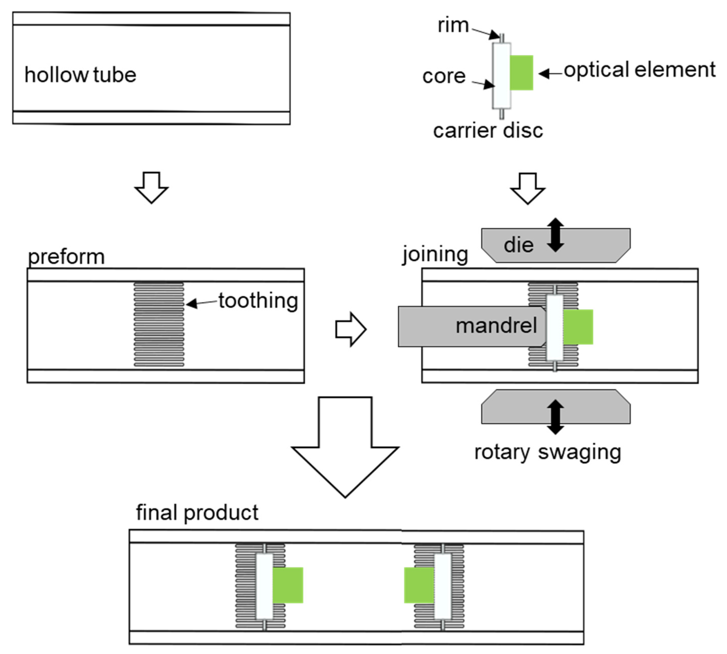
Table 1 shows the simulated parameters of the joining partners. The teeth have a height of 0.7 mm, a base of 1.73 mm and a flank angle of 100°. The integration is simulated with 4, 6 and 8 teeth. The sensor-bearing disc consists of a core diameter of 10 mm and a rim diameter of 22 mm. The disc edge is simulated as chamfered and not chamfered. Increasing the number of teeth increases the required force for the disc’s penetration and reduces the form-fit of the joint. A similar behavior can be observed when increasing the contact surface on the disc’s rim. With the aid of numerical investigations, the geometric design of the carrier disc and the internal toothing are analyzed with respect to the resulting force and the form-fit.
To set up the simulation model, preliminary investigations are undertaken on a small segment of the entire model using the explicit Abaqus solver. Furthermore, to reduce the computational time for numerical investigation of the complex rotary swaging process, only 10 tool strokes are set to achieve the final diameter reduction.

3.1. Preliminary Simulation and Basics of the Model Parameters

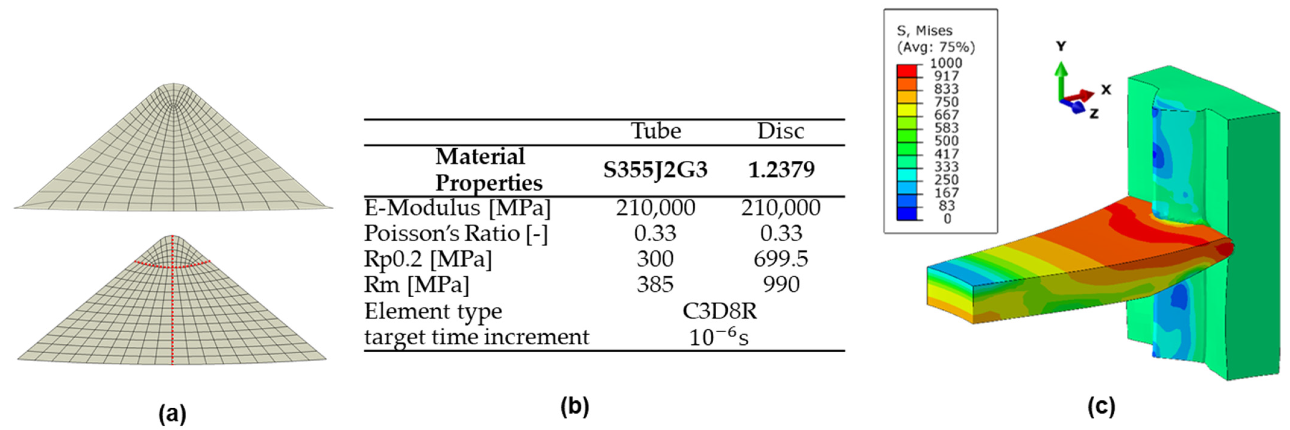
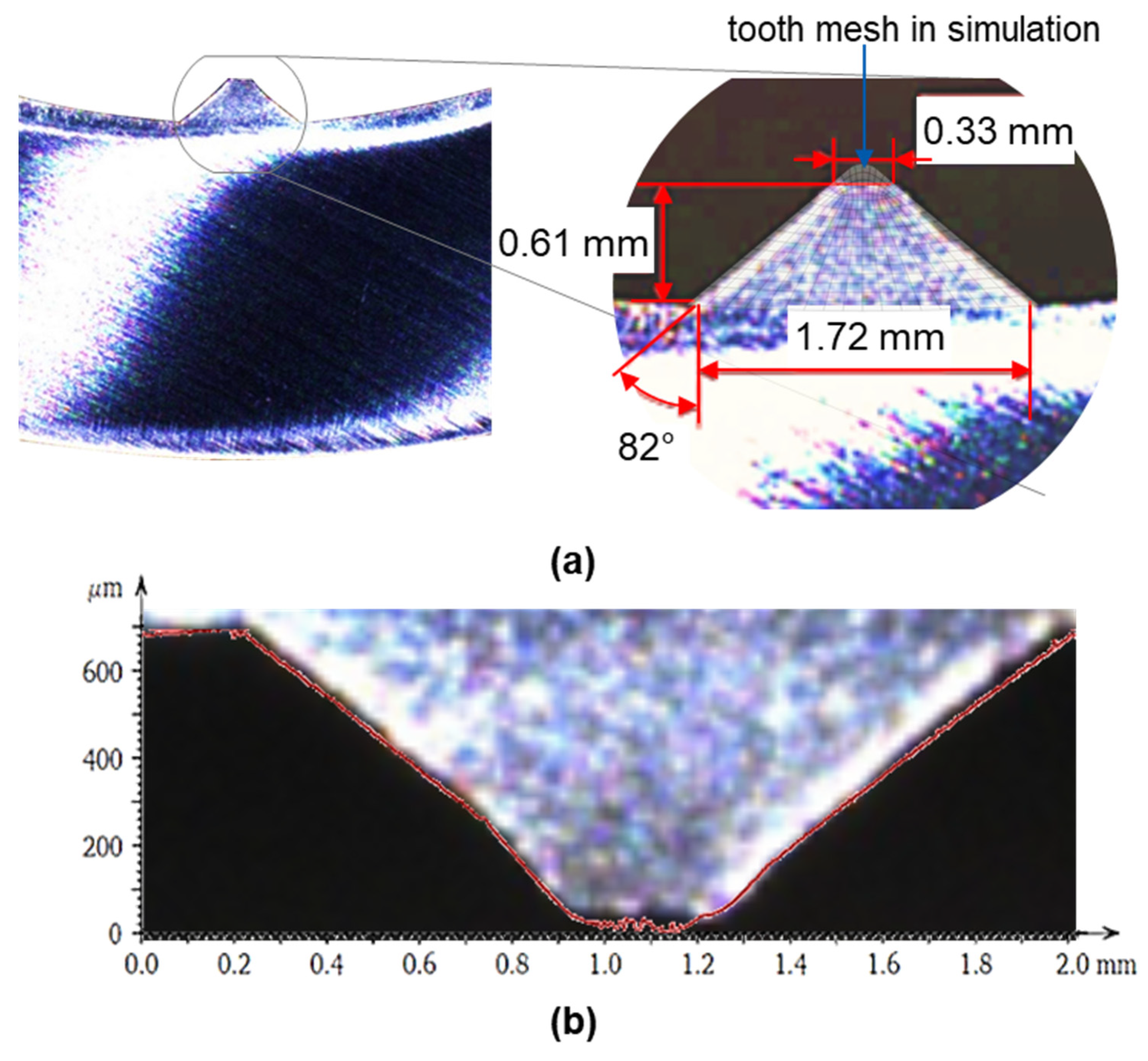
Due to the high deformation of the teeth during the disc’s penetration, the mesh shape and the mass scaling need to be optimized to improve the accuracy of the simulation. In a standard Abaqus mesh algorithm, the inner elements become very small in a triangular shape, like a tooth. As a result, these elements become completely flat at larger deformations, and the simulation will be aborted. In order to avoid this problem, internal paths with specific node distribution are created. Figure 3a shows the standard mesh at the top with the internal elements becoming smaller and the created mesh with the designed nodes paths in red at the bottom. Furthermore, the Arbitrary Lagrangian–Eulerian Algorithm for remeshing (ALE) was used to create a more uniform aspect ratio within the mesh. Figure 3b,c show the simulation parameters and the resulting deformation behavior during the joining process.
The different materials allow the tooth to undergo plastic deformation earlier, making it easier for the rim to penetrate. When the rim reaches the bottom of the tooth, the compressive stress increases, and the rim begins to deflect; see Figure 3c. To accurately simulate the joining behavior of the disc between the teeth and the disc, a 3D section with a thickness and a height of 5 mm of the tube is modeled, 
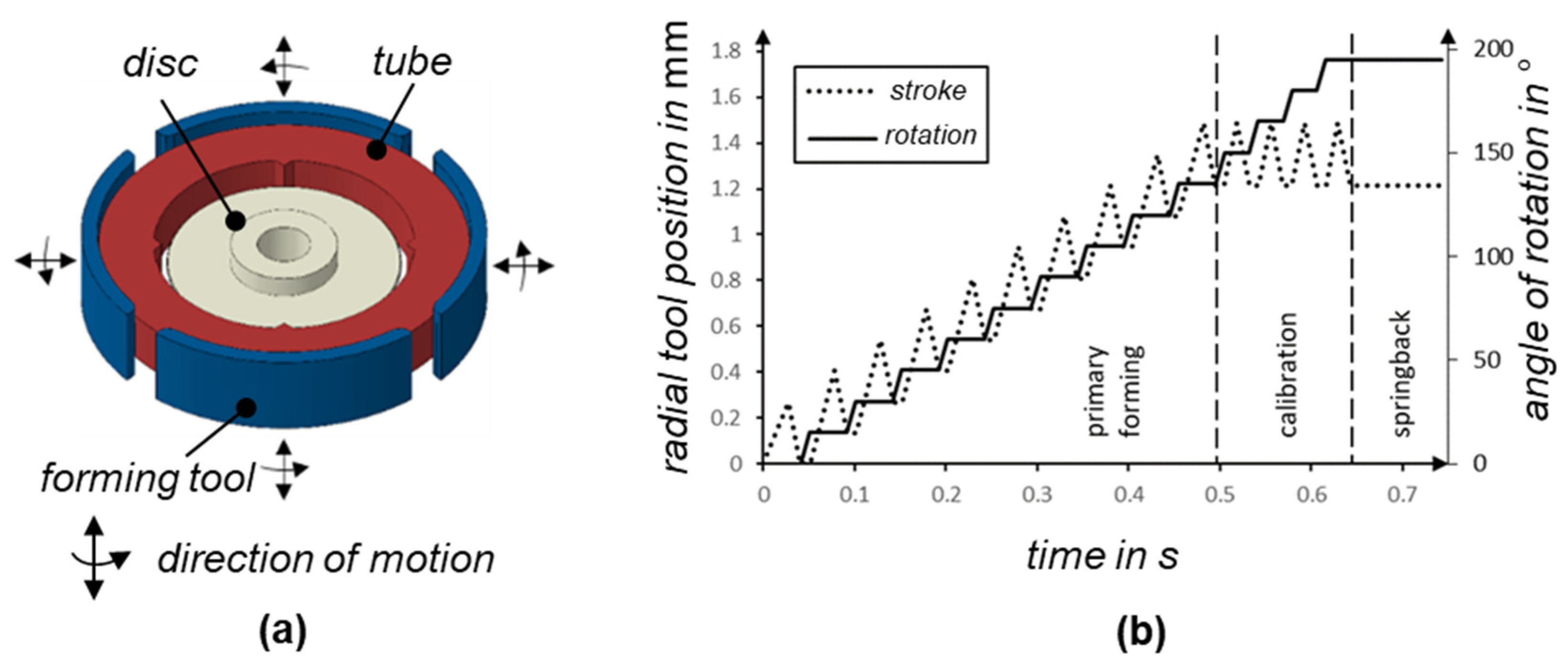
Figure 4a. This allows the joining behavior to be modeled with a higher accuracy in both the axial and radial directions. The modeled tube section includes a variable number of teeth, the carrier disc and the four tools. Since torsional loads occur during workpiece rotation when the forming tools are closed during rotary swaging, the influence of torsion during rotary swaging is neglected, and the simulation model is set up for torsion-free rotary swaging of the tube, so that the workpiece only rotates when the tools are open; see Figure 4b.
Figure 4b shows the movement of the tools. After ten forming strokes, four calibration strokes are carried out to ensure a uniform stress distribution between the disc and the tube teeth. At the end of the forming process, the boundary condition that fixes the disc is removed. Due to the stress relief and the resulting spring-back, which manifests as minimal axial disc displacement, the disc reaches its final position.

3.2. Investigating the Effect of the Rim Geometry

As shown in 
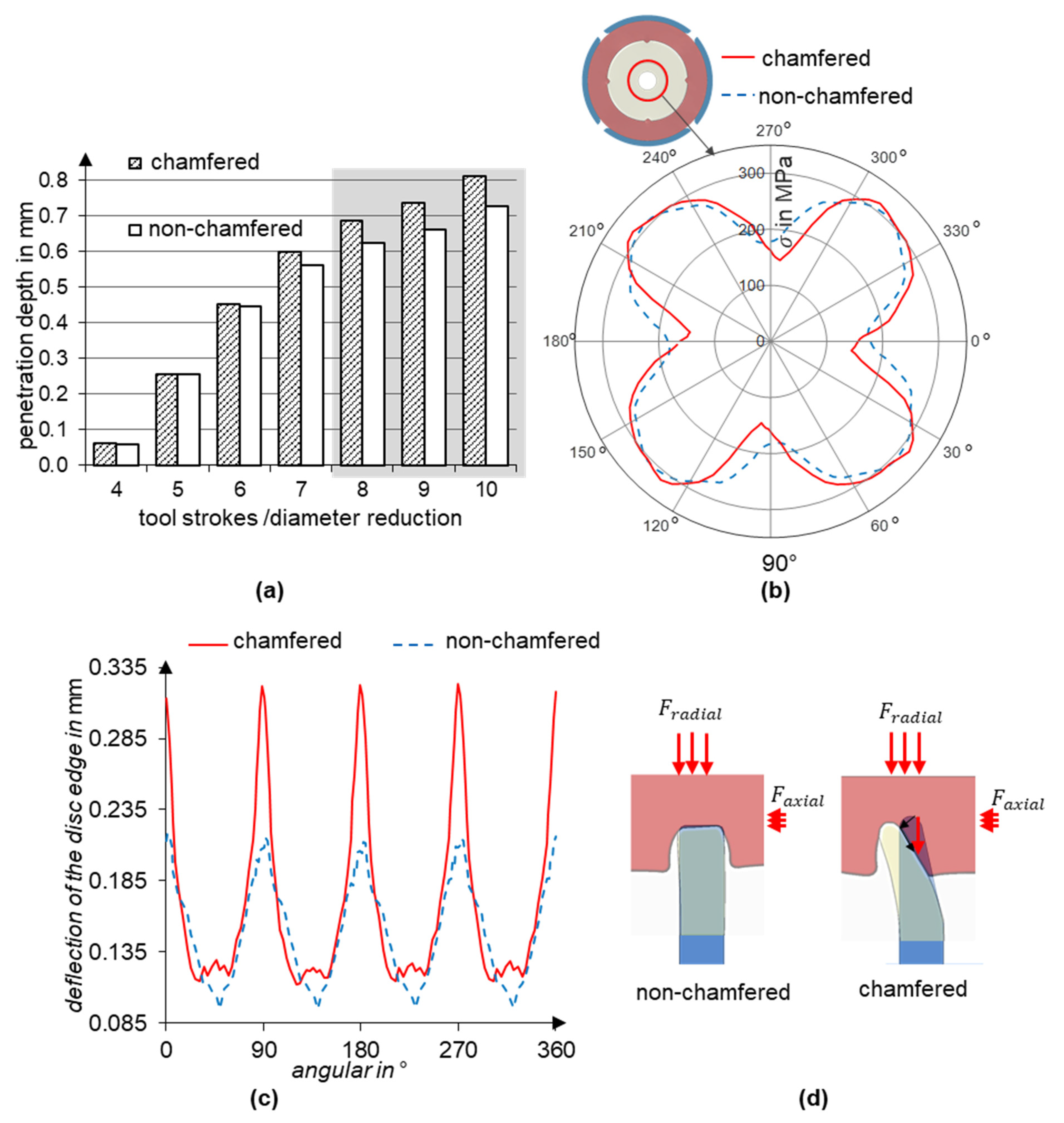
Table 1, the influence of the geometry of the rim edge is investigated by comparing two main variants: a chamfered and a non-chamfered rim edge. In the non-chamfered rim edge variant, the contact surface is twice as large as in the variant with the chamfered edge. Therefore, it is expected to require a higher radial joining force and achieve a lower penetration depth in this case.
In addition to evaluating the deformations, the force fit is also analyzed using the radial stress. The simplifying assumption is made that after the integration of the carrier disc, only radial stresses appear at the boundary between the thick core and the rim, as visualized in Figure 5b.
Evaluation of the penetration depth shows that the chamfered rim achieves only about a 10% higher penetration depth (Figure 5a) and about a 3% lower maximum radial stress (Figure 5b) compared to the non-chamfered edge. However, a significant difference can be observed in the axial deflection behavior of the two rim geometries shown in Figure 5c.
As can be seen in Figure 5c, both disc variants show wave-like axial deflection, with the peaks at the teeth resulting from the disc’s penetration. However, the chamfered variant shows significantly higher peaks. An increased alternate rim deflection between the toothed and non-toothed areas indicates a higher axial disc grip within the teeth. Both disc variants are subjected to nearly identical radial and axial forces, whereby the radial force results from the radial forming tools and the axial force results from the material flow in the axial direction. However, the chamfered rim variant experiences a higher axial deflection due to the chamfer geometry; see Figure 5d. Due to the higher penetration depth and the correlated increase in the alternate axial rim deflection, the chamfered disc variant is considered in subsequent investigations.

3.3. Investigating the Number of Teeth

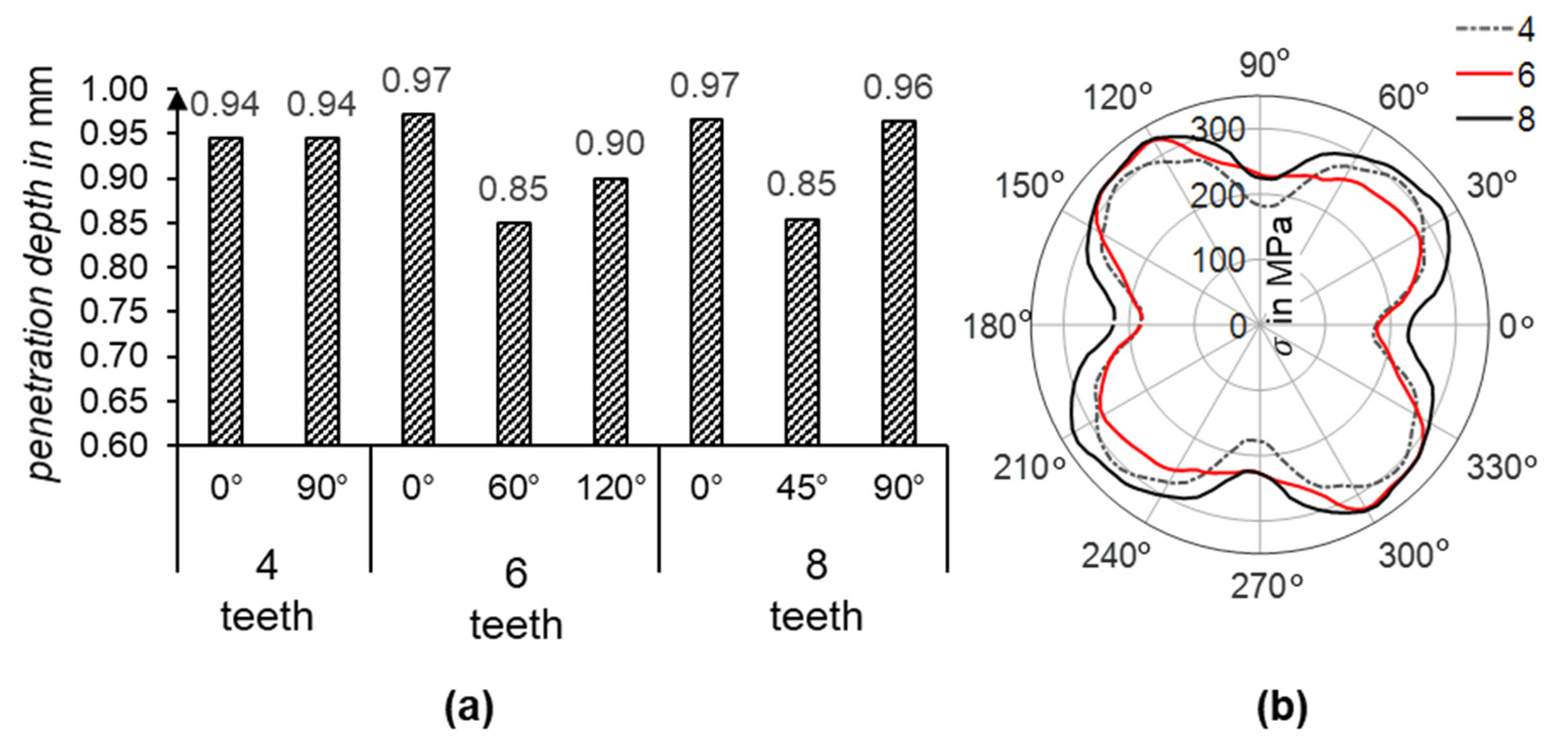
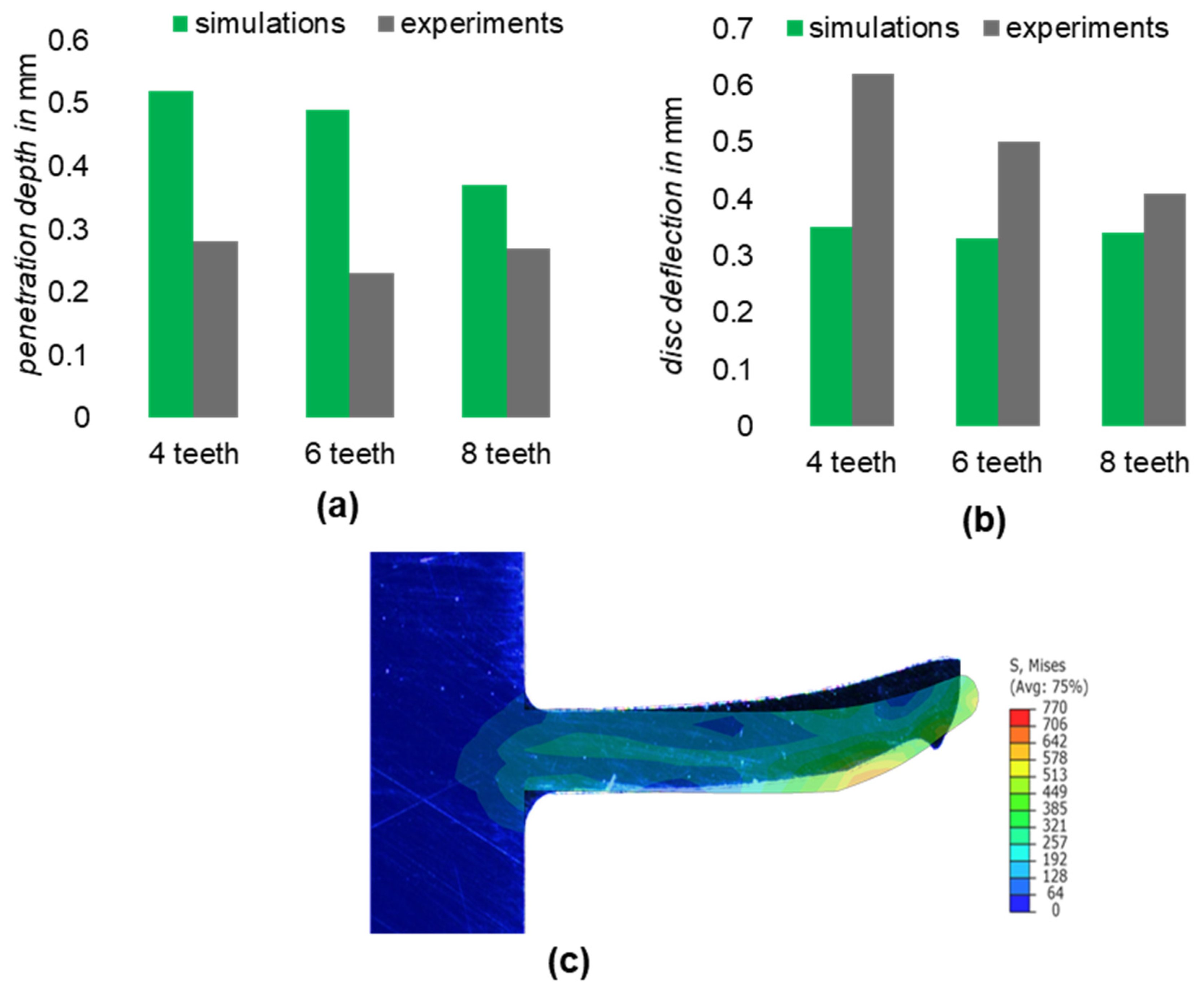
Increasing the number of teeth obviously increases the contact area between the teeth and the disc, which increases the required joining force and decreases the achievable penetration depth. To investigate the effect of the number of teeth on the formation of the joint, the number of teeth is varied between 4, 6 and 8 in the following tests. In this variant, the disc with the chamfered rim was used. The simulation results show no significant differences in the depth of the disc’s penetration; see Figure 6a. On the other hand, the radial stress distribution is more dependent on the number of teeth, as can be seen in Figure 6b. The difference in radial stress between four and eight teeth is approximately 40 MPa.
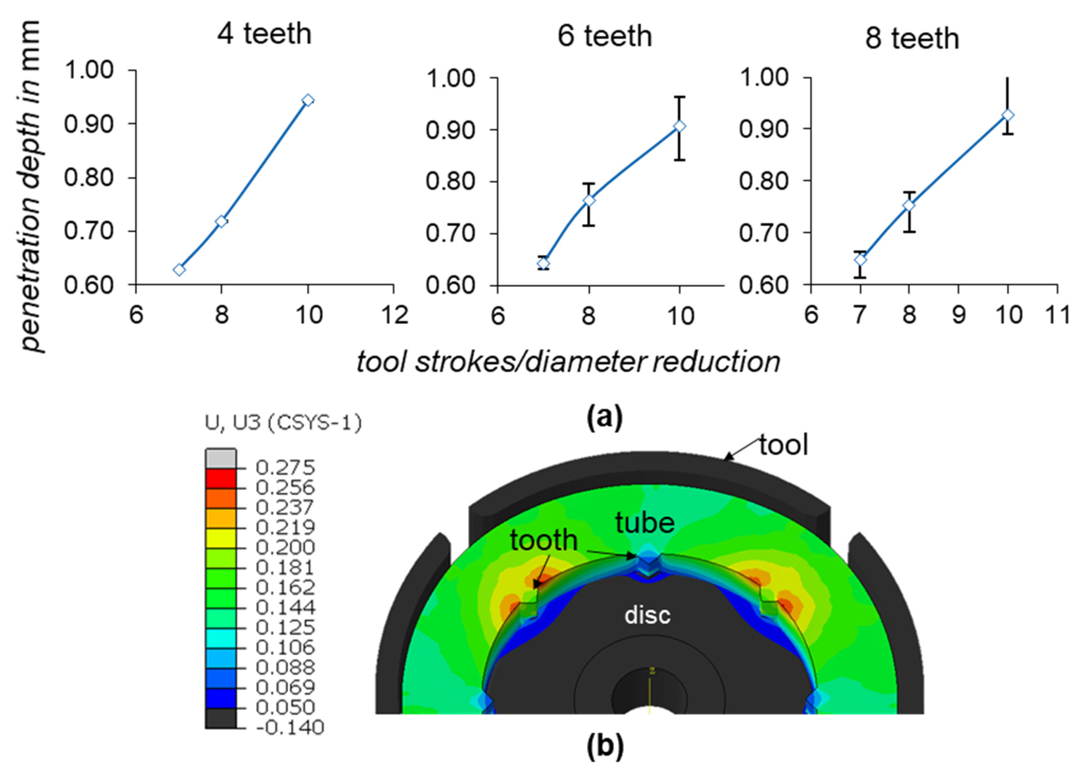
However, the results indicate that increasing the number of teeth seems to lead to asymmetrical disc penetration into the teeth, as well as an inhomogeneous distribution of radial stress onto the disc. The radial stress distribution appears to have four distinct amplitudes regardless of the number of teeth. To clarify this behavior, both the disc’s penetration and the development of radial stress during the rotary swaging process were analyzed. See Figure 7.
The average penetration of all the teeth (blue curve) and the deviation in the tooth penetration (error bars) are shown in Figure 7a for the three cases. It can be seen that in the case of four teeth, linear progression of the disc penetration occurs at almost the same level for all the teeth, and the deviation in the penetration depth is almost zero. In the case of 6 and 8 teeth, the penetration becomes less linear and shows significant deviation between the teeth. This deviation is even more distinct in the case of 6 teeth, and the progression of the penetration appears to be more non-linear.
The reason for this behavior was identified as radial force propagation from the tools into the tube during the rotary swaging process. Since only four oscillating tools strike the tube each time, some of the teeth are located outside the path of the acting radial force. At this point, the tube material starts to flow into the unloaded gap between the tools, causing the previously established radial stress to be released. Figure 7b illustrates the material flow at three teeth in the case of eight teeth during a forming increment.
As can be seen in Figure 7b, the axial material flow at the teeth in the area of the gaps between the tools is much higher than at the teeth in the tool engagement zone. This alternating reduction in the previously established radial stress through incremental tool striking and workpiece rotation explains why, regardless of the teeth variants, the resulting stress distribution shows the same pattern. This pattern is determined by the number of rotary swaging tools.
Although this typically has less effect on the roundness and surface finish of rotary swaging workpieces, it leads to a distortion in the radial stress created between the disc and the die. To mitigate this issue, the teeth should ideally be arranged so that they remain within the effective tool area during rotation.

4. Experimental Investigations

4.1. Preliminary Trails

In this work, the internal toothing of the tube is created according to rotary swaging. A mandrel with toothed cavities is inserted into the tube during rotary swaging. As the rotary swaging proceeds, the material flows into these cavities, forming the internal teeth. Figure 8a presents a cross-section of the resulting tooth geometry.
Figure 8a shows that the created tooth deviates slightly from the one used in the simulation, with a tooth height of 0.6 mm instead of 0.7 mm. Investigation has shown that this small deviation is due to a deviation in the mandrel processing, as shown in Figure 8b, where there is an overlap between the tooth geometry and the measured contour of the mandrel cavity.
Experimental trials were conducted on disc joining in pre-toothed tubes with 4, 6 and 8 teeth, and the results were compared to the simulation. After the tube is toothed, the discs are attached to a mandrel and positioned within the pre-toothed section inside the tube. The tube diameter is then reduced according to recess rotary swaging, and the disc is joined inside the tube. Subsequently, the quality of the joint is determined visually using metallographic cross-section images. In addition to the penetration depth, the deflection of the disc rim is also evaluated as a characteristic of the force-fit joining. To prevent springback during cutting, the specimens are fully embedded into resin. Figure 9 shows the results of this comparison, where the deviation found in the tooth height is subtracted from the penetration depth in the simulation.
As can be seen in Figure 9a, the penetration depth of the disc into the teeth is higher in the simulation than in the experiments and varies with the number of teeth. Conversely, the disc deflection, shown in Figure 9b, is significantly higher in the experiments than in the simulation. However, comparison reveals that the lowest deviation between the simulation and experiments occurs for 8 teeth. Investigation into the cause of this deviation has attributed it to a higher tooth stiffness due to not considering the strain-hardening effect in the teeth during the preforming process.
Since the simulation was primarily focused on analyzing the penetration behavior of the disc into the teeth and faced challenges related to mesh generation, as discussed in Section 3.1, the pre-toothing process was not considered in the simulation. As a result, the teeth are harder for the disc to penetrate, and the disc’s edge undergoes plastic deformation and higher deflection because a smaller penetration depth can be achieved, as shown in Figure 9c.
In order to achieve a greater penetration depth and to prevent excessive disc rim deflection in the incremental joining process, the disc-fixing mandrel is designed to move freely in the axial direction, allowing for axial displacement of the disc after initial penetration. The tube’s final radius is then further reduced by 2 mm compared to the experimental results in Figure 9. The results of this modification are displayed in Figure 10.
As observed in Figure 10a, the joined disc achieves a deflection of 1.1 mm and a penetration depth of 0.35 mm, ensuring a stable disc joint in the tube. Comparing these results to the simulation results in Figure 9 for a chosen tube pre-toothed with 8 teeth, where the disc deflection is 0.34 mm and the penetration depth is 0.37 mm, we achieved a very similar penetration depth and a higher disc deflection. The achieved higher disc deflection is, however, a direct result of the greater diameter reduction. The deformation behavior of the disc between the simulation and the experimental results in Figure 10d shows greater plastic deformation in the regions in contact with the teeth in the experiment. This is due to the fact that the strain-hardening effect in the teeth is not taken into account, as mentioned above.

4.2. Sensor Integration

Based on the achieved results in Figure 10, the successful integration of two discs was demonstrated. For a set distance between the discs of 80 mm, a distance of 79.6 mm was achieved after joining. However, the two discs were tilted by 0.8° relative to each other, which is deemed unacceptable for the optical sensor. This observed disc tilt may be due to non-symmetric forming of the tube due to small deviations in the timing of the strokes of the different tool segments or because the wall thickness is not perfectly uniform. Given that the alignment of the two mirrors with each other has the tightest tolerance in the designed sensor (Figure 1), the design was simplified to measure only the in-plane displacement (torsion and bending loads), and the mirrors were removed. Figure 11 displays a successfully integrated optical sensor, along with a schematic illustration of the sensor.

4.3. Non-Destructive Evaluation of the Joint Quality

The integrated sensor is used to non-destructively evaluate the quality of the joint. The sensor tube is subjected to bending and torsional loads on testing machines, which are detected using the integrated sensor. An inadequate joint would result in hysterical behavior or a zero-point shift in the sensor signal. The tube is incrementally loaded with a maximum bending force of 1500 N and a maximum torsional load of 300 Nm, as visualized in Figure 12.
As can be seen, both sensor signals in Figure 12 show hysteresis-free and zero-point stable behavior, confirming a successful integration.

5. Future Work

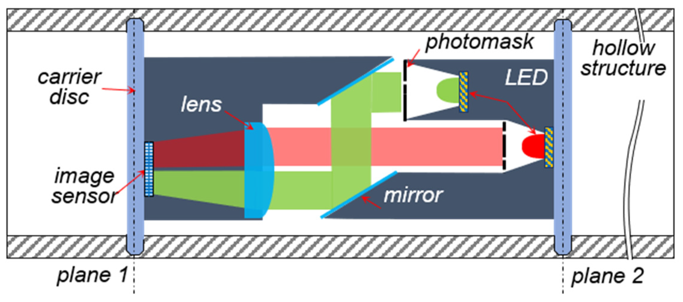
Ensuring the required parallel alignment of the built-in mirrors in the presented sensor design (
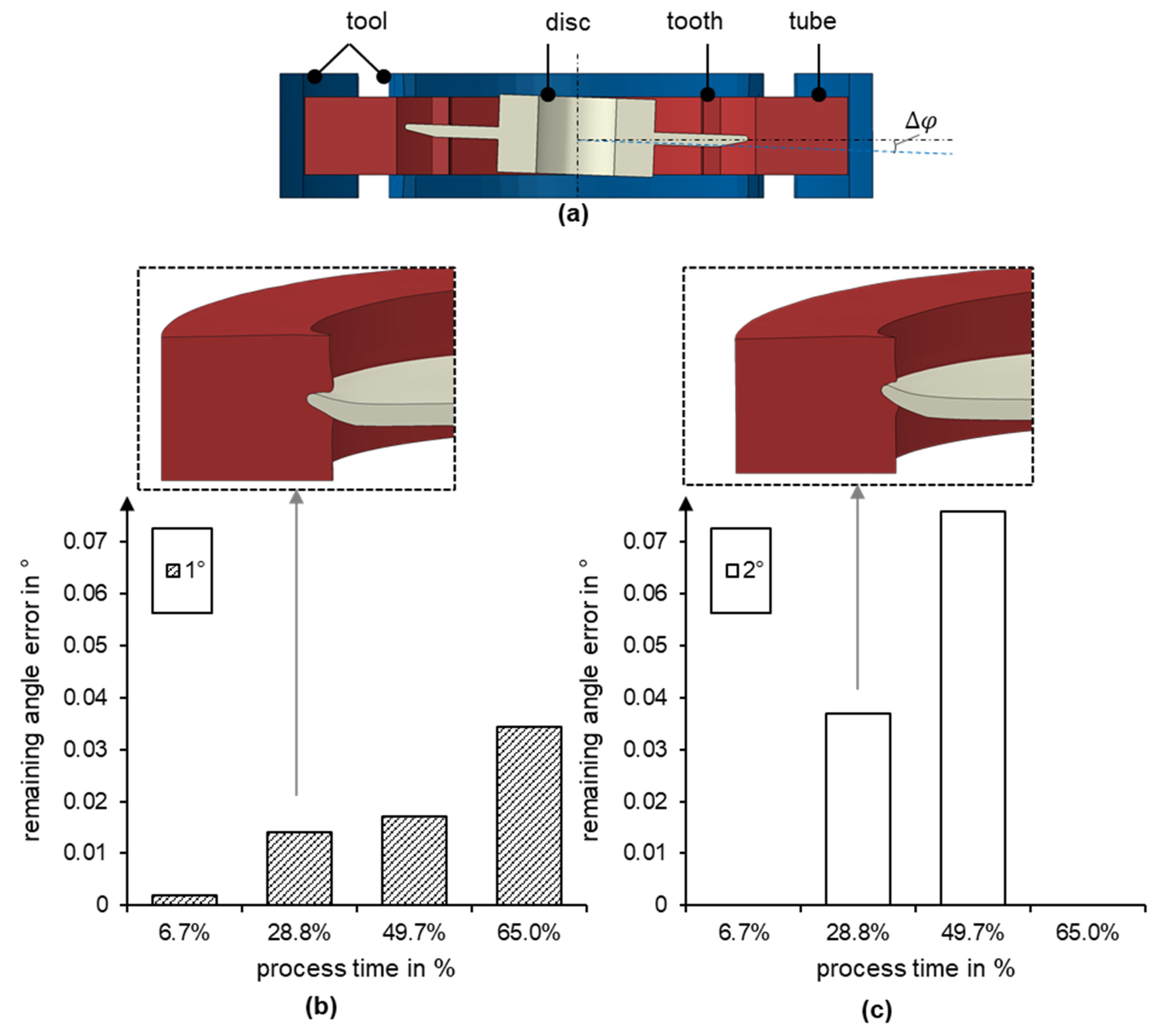
Figure 1) is the key challenge during integration into the tube. To address this challenge, it is imperative to prevent or control possible disc tilting during the rotary swaging process through the implementation of a closed-loop controller, as discussed in [19]. In the case of closed-loop position control, a critical aspect is the ability to manipulate the disc’s position inside the tube during the joining process. Assuming this ability, numerical simulations were conducted to investigate the possibility of compensating for disc tilting and to examine the available time window for correcting the disc position during disc joining. In the numerical investigation, the disc is initially tilted by φ = 1 ° and φ = 2 ° . See Figure 13a. For an initial tilt of 1°, the disc tilt is corrected at four different advance times in the process, which was driven by the previous investigations. See Figure 13b. Figure 13c shows the results for an initial tilt of 2° for two candidate process times.
As can be seen in Figure 13, the simulation results demonstrate that the earlier the misalignment is corrected and the smaller the error is, the smaller the remaining angle error. The stiffness ratios between the two joining partners ensure a form-fit connection despite the subsequent change in position for tilt correction.

6. Conclusions

This study presents a novel approach to integrating non-contact optical sensors into metallic structures using metal forming technology. Within the paper, we investigated the possibility of integrating highly sensitive optical sensors with the required high positional accuracy using rotary swaging. The investigations have demonstrated the possibilities offered by appropriate design of the joining parameters and the joining process. Additionally, the studies have shown that the number of tools and the contact area during rotary swaging directly affect the distribution of radial stresses in the integrated disc. When a tooth is located in the gap between the tools during a forming increment, the material flow at that point results in a partial reduction in the previously created radial stress. As the tube rotates and the gap between the teeth changes, non-linear radial stress is created, which increases with the depth of penetration. The integration of the two discs at a specific distance from each other resulted in a deviation of only 0.6% from the desired distance, but the total tilt of the discs was 0.8°. Permitting higher tilting of the carrying the discs required simplification of the design of the optical sensor to ensure its functionality. Full functionality with no hysteresis is provided by the integrated sensor for bending force and torque measurement. To achieve higher positional accuracy during the disc joining process, position-controlled disc joining can be applied to improve the achievable positional accuracy. The numerical results show the potential to correct possible angle tilt errors during the joining process. Future work will implement and experiment with this control approach. In addition, the increased stiffness of the teeth during their pre-forming needs to be reduced, for example, by applying hot rotary swaging during the pre-toothing process.

Author Contributions

Conceptualization, P.G. and N.A.-B.; methodology, P.G., N.A.-B. and P.H.; software, N.A.-B.; validation, N.A.-B. and P.H.; formal analysis, N.A.-B. and P.H.; investigation, P.H. and N.A.-B.; resources, P.G.; data curation, P.H. and N.A.-B.; writing—original draft preparation, N.A.-B. and P.H.; writing—review and editing, P.G.; visualization, N.A.-B. and P.H.; supervision, P.G.; project administration, P.G. and N.A.-B.; funding acquisition, P.G. and N.A.-B.; All authors have read and agreed to the published version of the manuscript.

Funding

This research was funded the Deutsche Forschungsgemeinschaft (DFG—German Research Foundation), grant number: 460244297. The APC was funded by the Open Access Publishing Fund of Technical University of Darmstadt.

Data Availability Statement

No new data were created or analyzed in this study. Data sharing is not applicable to this article.

Conflicts of Interest

The authors declare no conflict of interest.

References

  1. Alves, L.M.; Silva, F.L.R.; Afonso, R.M.; Martins, P.A.F. A new joining by forming process for fixing sheets to tubes. Int. J. Adv. Manuf. Technol. 2019, 104, 3199–3207. [Google Scholar] [CrossRef]
  2. Mori, K.I.; Bay, N.; Fratini, L.; Micari, F.; Tekkaya, A.E. Joining by plastic deformation. CIRP Ann.—Manuf. Technol. 2013, 62, 673–694. [Google Scholar] [CrossRef]
  3. Schubert, A.; Wittstock, V.; Jahn, S.F.; Müller, B.; Müller, M. Joining by forming of piezoceramic macro-fiber arrays within micro-structured surfaces of aluminum sheets. Prod. Eng. 2014, 8, 195–205. [Google Scholar] [CrossRef]
  4. Al-Baradoni, N.; Groche, P. Sensor-integrated structures in mechanical engineering: Challenges and opportunities for mechanical joining processes. Prod. Eng. 2022, 16, 423–434. [Google Scholar] [CrossRef]
  5. Schubert, A.; Wittstock, V.; Koriath, H.-J.; Jahn, S.F.; Peter, S.; Müller, B.; Müller, M. Smart metal sheets by direct functional integration of piezoceramic fibers in microformed structures. Microsyst. Technol. 2014, 20, 1131–1140. [Google Scholar] [CrossRef]
  6. Tiedemann, R.; Pille, C.; Dumstorff, G.; Lang, W. Sensor integration in castings made of Aluminum—New approaches for direct sensor integration in aluminum high pressure die casting. Key Eng. Mater. 2017, 742, 786–792. [Google Scholar] [CrossRef]
  7. Troughton, M.J. (Ed.) Chapter 17—Adhesive Bonding. In Handbook of Plastics Joining, 2nd ed.; William Andrew Publishing: Boston, MA, USA, 2009; pp. 145–173. [Google Scholar] [CrossRef]
  8. Müller, M.; Müller, B.; Hensel, S.; Nestler, M.; Jahn, S.F.; Müller, R.; Schubert, A.; Drossel, W.-G. Structural integration of piezoceramic fibers in deep drawn sheet metal for material-integrated health monitoring. Mechatronics 2016, 34, 100–110. [Google Scholar] [CrossRef]
  9. Brenneis, M.; Türk, M.; Groche, P. Integration of smart materials by incremental forming. Appl. Mech. Mater. 2012, 104, 115–121. [Google Scholar] [CrossRef]
  10. Groche, P.; Krech, M. Efficient production of sensory machine elements by a two-stage rotary swaging process—Relevant phenomena and numerical modelling. J. Am. Acad. Dermatol. 2017, 242, 205–217. [Google Scholar] [CrossRef]
  11. Krech, M.; Trunk, A.; Groche, P. Controlling the sensor properties of smart structures produced by metal forming. J. Am. Acad. Dermatol. 2018, 262, 541–550. [Google Scholar] [CrossRef]
  12. Al-Baradoni, N.; Krech, M.; Groche, P. In-process calibration of smart structures produced by incremental forming. Prod. Eng. 2020, 15, 79–87. [Google Scholar] [CrossRef]
  13. Krech, M. Adaptive Forming Process for the Production and Simultaneous Calibration of Metallic Structures with Component-Integrated Force and Torque Sensors. Adaptiver Umformprozess zur Herstellung und Simultanen Kalibrierung von Metallischen Strukturen mit Bauteil; Shaker Verlag: Düren, Germany, 2020. [Google Scholar]
  14. Al-Baradoni, N.; Groche, P. Sensor Integrated Load-Bearing Structures: Measuring Axis Extension with DIC-Based Transducers. Sensors 2021, 21, 4104. [Google Scholar] [CrossRef] [PubMed]
  15. Alves, L.M.; Silva, C.M.A.; Martins, P.A.F. End-to-end joining of tubes by plastic instability. J. Am. Acad. Dermatol. 2014, 214, 1954–1961. [Google Scholar] [CrossRef]
  16. Alves, L.M.; Afonso, R.M.; Silva, C.M.A.; Martins, P.A.F. Boss forming of annular flanges in thin-walled tubes. Mater. Process. Technol. 2017, 250, 182–189. [Google Scholar] [CrossRef]
  17. Alves, L.M.; Silva, C.M.A.; Martins, P.A.F. Joining by plastic deformation. Key Eng. Mater. 2018, 767, 25–41. [Google Scholar] [CrossRef]
  18. Al-Baradoni, N.; Groche, P. Identification of the sensory properties of image-based multi-axis force/torque sensors. In Proceedings of the Sensors and Measuring Systems, 21th ITG/GMA-Symposium, Nuremberg, Germany, 10–11 May 2022; pp. 1–6. [Google Scholar]
  19. Al-Baradoni, N.; Groche, P. Integration of optical sensors into load-bearing structures: Opportunities and challenges. In Proceedings of the ForTech Bulk 2022: Forming Technology Network Bulk 2022, Stuttgart, Germany, 18–19 May 2022; Universität Stuttgart, Institut für Umformtechnik: Stuttgart, Germany, 2022; pp. 58–63. [Google Scholar]
Figure 1. Schematic design of the optical sensor according to [14].
Jmmp 08 00060 g001
Figure 2. Design of the joining partners [4].
Jmmp 08 00060 g002
Figure 3. Preliminary simulation and basics of model parameters. (a) Tooth mesh design, (b) simulation set parameters and (c) achieved disc penetration behavior.
Jmmp 08 00060 g003
Figure 4. (a) Model setup for the simulation of the design parameters and (b) tool kinematics.
Jmmp 08 00060 g004
Figure 5. Effect of rim edge on the joining process, (a) on the depth of penetration and (b) on the radial joining force, (c) axial edge deflection over the whole disc circumference and (d) visualization of the influence of the chamfer on the force distribution at the rim.
Jmmp 08 00060 g005
Figure 6. Effect of number of teeth on the joining process: (a) on the penetration depth at the teeth, (b) on the radial stress distribution at the disc.
Jmmp 08 00060 g006
Figure 7. Formation of the joining during tube rotary swaging. (a) Disc penetration in the last three increments for the teeth variation and (b) axial material flow at the teeth during the swaging process.
Jmmp 08 00060 g007
Figure 8. Cross-section of the resulting tooth geometry, (a) overlapping of the tooth geometry and the contour of the mandrel in red (b).
Jmmp 08 00060 g008
Figure 9. A comparison between simulation and experimental results. The penetration depth and disc deflection for the three teeth variations in (a,b). (c) The disc deformation.
Jmmp 08 00060 g009
Figure 10. Successful disc integration into the tube. (b,c), integrated disc inside the tube, (a) cross-section images of the integrated disc and (d) deformation behavior compared to the simulation.
Jmmp 08 00060 g010
Figure 11. Successfully integrated optical sensor for measuring bending and torsional loads with an illustration of the integrated sensor.
Jmmp 08 00060 g011
Figure 12. Sensor behavior of the forming integrated optical-based sensor under (a) torsional load and (b) bending load.
Jmmp 08 00060 g012
Figure 13. Simulation position-controlled disc integration. Simulation model set-up (a) and remaining tilting after tilt correction at different process stages for initial errors of 1° (b) and 2° (c).
Jmmp 08 00060 g013
Table 1. Material and parameter variation for both joining partners.
S355J2G3 steel1.2379 steel
Jmmp 08 00060 i001Jmmp 08 00060 i002
Disclaimer/Publisher’s Note: The statements, opinions and data contained in all publications are solely those of the individual author(s) and contributor(s) and not of MDPI and/or the editor(s). MDPI and/or the editor(s) disclaim responsibility for any injury to people or property resulting from any ideas, methods, instructions or products referred to in the content.

