Article

Minimizing Dimensional Defects in FFF Using a Novel Adaptive Slicing Method Based on Local Shape Complexity

1
Mechanical Laboratory of Sousse (LMS, ENISo), University of Sousse, Sousse 4023, Tunisia
2
Department of Industrial Engineering, College of Engineering, King Saud University, Riyadh 11421, Saudi Arabia
3
Department of Mechanical Engineering, College of Engineering, Imam Mohammad Ibn Saud Islamic University (IMSIU), Riyadh 11432, Saudi Arabia
*
Author to whom correspondence should be addressed.
J. Manuf. Mater. Process. 2024, 8(2), 59; https://doi.org/10.3390/jmmp8020059
Submission received: 22 January 2024 / Revised: 1 March 2024 / Accepted: 1 March 2024 / Published: 11 March 2024
(This article belongs to the Topic Additive Manufacturing of Architected Metallic Materials)

Abstract

:
Additive Manufacturing (AM) has emerged as an innovative technology that gives designers several advantages, such as geometric freedom of design and less waste. However, the quality of the parts produced is affected by different design and manufacturing parameters, such as the part orientation, the nozzle temperature and speed, the support material, and the layer thickness. In this context, the layer thickness is considered an important AM parameter affecting the part quality and accuracy. Thus, in this paper, a new adaptative slicing method based on the cusp vector and the surface deviation is proposed with the aim of minimizing the dimensional defects of FFF printed parts and investigate the impact on the dimensional part tolerancing. An algorithm is developed to automatically extract data from the STL file, select the build orientation, and detect intersection points between the initial slicing and the STL mesh. The innovation of this algorithm is exhibited via adapting the slicing according to the surface curvature based on two factors: the cusp vector and the surface deviation. The suggested slicing technique guarantees dimensional accuracy, especially for complex feature shapes that are challenging to achieve using a uniform slicing approach. Finally, a preview of the slicing is displayed, and the G-code is generated to be used by the FFF machine. The case study consists of the dimensional tolerance inspection of prototypes manufactured using the conventional and adaptive slicing processes. The proposed method’s effectiveness is investigated using RE and CMM processes. The method demonstrates its reliability through the observed potential for accuracy improvements exceeding 0.6% and cost savings of up to 4.3% in specific scenarios. This reliability is substantiated by comparing the resulting dimensional tolerances and manufacturing costs.

1. Introduction

Over the past two decades, the market needs and demands for manufactured parts have changed considerably, prompting radical changes in the manufacturing processes. Driven by the development of the information technology tools that made it possible, among other things, to reduce or even eliminate intermediaries between the customer and the producer [1], Additive Manufacturing (AM), which is based on incremental layer-by-layer manufacturing [2], represents the ideal solution in the current situation of market saturation associated with the scarcity of raw materials [3,4]. This model offers perfectly personalized production that meets the customer’s needs at a reasonable cost within a limited timeframe [5]. Thus, Fused Filament Fabrication (FFF) is one of the most used AM processes for prototyping and functional parts [6,7,8]. Regarding the production of mechanical parts, the AM process, often presented as a new industrial revolution, opens the doors to the future [9,10]. The use of the AM process has been expanding in many other fields. The application of AM has reached an unprecedented scale in both academia and industry. For this reason, high precision is required, especially in critical fields where AM use is expanding in aerospace [8,11], medical [12,13,14], and tool-forming [15] fields.
Subsequently, the optimization of the mechanical properties and the Geometric Dimensioning and Tolerancing (GD&T) characteristics of parts obtained by AM is essential for educational, research, and industry applications. To undergo this optimization, the Design for Additive Manufacturing (DFAM) is a controversial issue. Despite some limitations in finding generalized suitability for different fields [16], DFAM can provide an important solution for AM optimization. The implementation of the FFF technique in industrial applications is still limited and has been delayed by issues of poor quality compared to the other AM technologies. This paper investigates the accuracy of FFF printed parts, aiming to optimize the FFF process through the implementation and enhancement of established adaptive slicing algorithms.
The rest of the paper is organized as follows: In Section 2, a review of related work is presented, followed by an overview of the errors due to the layering process in Section 3. Section 4 shows the proposed adaptative slicing method. In Section 5, a case study is presented to evaluate the proposed tool, followed by a discussion section. The conclusion is presented at the end.

2. Related Works

Several research investigations have been focused on the improvement of AM processes and overcoming the limitations and challenges imposed by several factors and key parameters, such as the mechanical proprieties of raw materials [17,18,19,20], dimensional and geometrical tolerances [21,22], non-assembly mechanisms [23], build orientation [24,25,26,27], thermal behavior [20,28], and microstructural characterization [28].
In the FFF process, the optimization of the quality, both in terms of surface roughness and accuracy, the manufacturing time, and the cost of 3D printed parts remain challenging for research. In this respect, O’Connor et al. evaluated the effects of a low-pressure manufacturing environment on mechanical properties (ultimate tensile strength, elongation at break, and tensile modulus), thermal behavior, and surface roughness (Ra) of the Polymer Material Extrusion (PME) process [29]. The experimental investigations included three materials, acrylonitrile butadiene styrene (ABS), polylactic acid (PLA), and polyamide 6 (PA6). Regarding surface roughness, the pressure reduction increases the arithmetic roughness average Ra for ABS and PLA materials. Boschetto et al. developed a geometrical model of the filament depending on the deposition angle and the layer thickness to predict the resulting part dimensions [30]. The model shows that the dimensional deviation is pared to zero for the vertical walls, and it increases for deposition angles less and greater than 90°. Goguelin et al. optimized the build orientation and the support structure implementation using the Bayesian method [25]. The findings proved the method’s efficiency compared to the grid method, especially with random build angles. Byun et al. [31] proposed a decision-making model for optimal build orientation selection with variable slicing. The build orientation is considered as one of the manufacturing factors of printing cost and time. Al-Tamimi et al. conducted experimental investigations to assess the influence of printing parameters—specifically layer thickness, nozzle temperature, printing speed, raster angle, and layer composition (ABS-PLA)—on various aspects of the printed material [32]. These aspects include mechanical properties, such as bonding modulus, compression modulus, and strength, as well as surface roughness (Ra, Rz, Rku, and Rsk), and dimensional variations related to shrinkage. To minimize the unavoidable staircase effect, Zhao et al. [33] decreased the layer thickness during the ‘uniform slicing’ (also named ‘direct slicing’), where the 3D part was sliced with the identical thickness throughout the whole part. This could result in a much longer printing time and increased costs. In adaptive slicing, the layer thickness was varied to consider the curvatures of the surface of the solid model in the vertical direction, reduce the staircase effect, and minimize the number of layers, thus decreasing the build time. For FFF, the minimal possible layer thickness was 0.127 mm and the maximum was 7.62 mm. The allowable staircase tolerance was measured by the cusp height. Zhao et al. conducted a numerical investigation in a case study with the aim of reducing the layer number while maintaining dimensional accuracy, albeit without experimental validations. Di Angelo et al. introduced a model for predicting the surface roughness of FFF-printed surfaces using the Pa index as an alternative to the Ra index [34]. The study primarily focused on the geometric modeling of Pa, considering the shape of the deposited filament with a constant layer thickness. Validation through comparisons was carried out through numerical investigations. In another study, Di Angelo et al. also optimized the surface quality and build cost by selecting the build orientation minimizing the staircase effect. The model uses S-metric selection evolutionary multi-objective algorithm (SMS-EMOA) to obtain the Pareto front for the choice of the best build orientation [35]. Furthermore, an estimation of the build time, surface quality (Pa), and support volume as functions of built orientation were suggested and the Technique for Order of Preference by Similarity to Ideal Solution (TOPSIS) method was employed for solution selection. Shao et al. tackled the challenges associated with processing extensive data models through the introduction of a layer merging-adaptive slicing approach [36]. Their approach aims to diminish data size by reducing the number of slices, achieved by increasing layer thickness in regions with substantial curvature and decreasing it in areas with high curvature changes. However, it is important to note that the case study, which focuses on the surface profile of a hemisphere part, has limitations. This particular geometry does not serve as a comprehensive guideline for evaluating achieved accuracy along all three axes and does not surpass the accuracy achieved with conventional layer thickness values (e.g., 0.2 mm). Table 1 summarizes the relevant literature investigating FFF manufacturing parameters to optimize part accuracy and surface quality.
The previous studies investigated various FFF parameters, including layer thickness, build orientation, printing speed, nozzle temperature, and pressure conditions, to optimize part quality. However, achieving reliability in integrating variable layer thickness as a parameter for optimizing feature quality in the FFF process remains a challenge. There is a need for comprehensive guidelines to bridge the gap between dimensional accuracy and adaptive slicing approaches for successfully manufacturing parts. The adoption of tolerances as communication support between design, manufacturing, and inspection phases, standard in subtractive manufacturing, has hindered the widespread use of FFF in industrial practices. There is a need for feature tolerances oriented towards design for Additive Manufacturing. In this paper, a new slicing technique is proposed to improve the dimensional accuracy of 3D-printed parts. The developed algorithm is used to adapt slicing according to the shape of the part features. An innovative technique combining the cusp height vector with the surface deviation threshold is used to develop an adaptive slicing method for minimizing dimensional defects. The impact of the developed method on the features’ dimensional tolerances is investigated through two case studies. These experimental investigations serve as a pilot study to incorporate tolerances as support for communication across drawing specifications, slicing processes, inspection phases, and cost assessments. By systematically integrating tolerances into the additive manufacturing workflow, this approach aims to enhance the overall quality and reliability of 3D-printed parts while aligning with industry standards and practices.

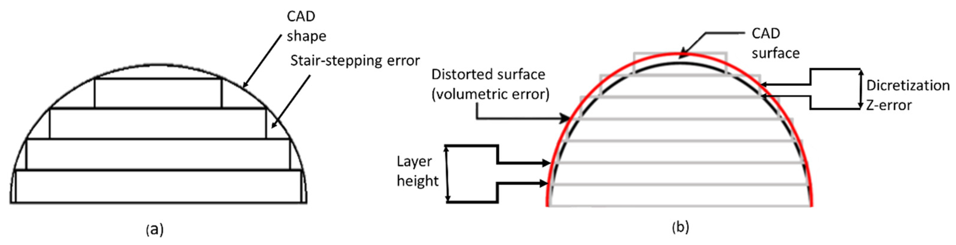
3. FFF Layering Errors

In FFF, a cube-shaped part can be constructed accurately by vertically stacking layers. However, models featuring curved or inclined surfaces are not likely to be as accurate as a cube. These geometries, when sliced and printed from the resulting layers, will suffer an inevitable loss of information. The layering error is responsible for the poor quality of Rapid Prototyping (RP) parts, i.e., it significantly affects the dimensional and geometrical tolerances of the obtained part. The FFF layering principle yields to the stair-stepping and distortion effects.
The stair-stepping effect is an obstacle for all layer manufacturing techniques, particularly in the production of inclined or curved surfaces. When considering planar surfaces of the part, the stair-stepping effect is expected to increase with the increasing layer thickness and decrease with the increasing part deposing angle. Horizontal cross-sections are obtained after the slicing process. In a horizontal plane, each section must obey the geometry of the original CAD model with acceptable accuracy, which is crucial to the entire process. However, each layer consists of a continuous cross-section through its thickness (i.e., in the Z-direction), so parts cannot precisely conform to the CAD geometry in the vertical plane depending on the shape complexity of the part, as illustrated in Figure 1a. Equally, the elliptic surface of extruded traces increases the workpiece’s surface roughness, and the overall accuracy will be more negatively impacted. In addition, depending on the printing orientation, stairs are generated inside or outside the model surface yielding to geometrical distortion effects shown Figure 1b.
The increase in layer thickness yields a reduction in the layer number, and then expedites the AM process. However, thick layers tend to minimize the part surface accuracy due to the stair-stepping effect that is inherent to layered manufacturing (Figure 2). This repercussion is often minimized by decreasing the thickness of each build layer. Unfortunately, this solution increases the part build time to an unsuitable level.
This error is always present in every classical FFF process, and this is essentially due to the constant layer height over the overall geometry. Thus, this paper addresses the layering error issue and presents an adaptive slicing algorithm varying the layer thickness according to the local geometry. The algorithm is based on three major concepts: the choice of criterion for accommodating complexities of surfaces, the recognition of key characteristics and features of the object, and the development of a grouping technique for facets characterizing the object.

4. Proposed Method

The proposed method aims to improve an existing slicing code through the implementation of an adaptive algorithm. The innovative adaptive slicing represents a significant leap forward for FFF 3D printing. Unlike standard adaptive slicing techniques, which primarily rely on layer height adjustments, this method introduces a groundbreaking approach. By meticulously analyzing the surface deviation of each slice, it empowers FFF 3D printers to produce parts with enhanced quality. This innovation mitigates dimensional errors and the notorious ‘staircase effect’. In essence, it transforms the FFF 3D printing process in terms of what is achievable in terms of the print dimensional accuracy.
The Inclusion of surface deviation as an inspection parameter, in conjunction with cusp height, in the developed adaptive slicing algorithm provides improved control over local geometry variations. The cusp vector height, typically used to determine overhang angles α for support structure generation, can be repurposed to address the staircase effect in standard slicing (Figure 3a). However, when layer thickness varies, similar results may occur despite varying surface deviations between consecutive layers. Figure 3b illustrates this scenario, where the cusp vector heights C1 and C2 are equal despite the difference between the correspondent section areas. Hence, the surface deviation parameter is designated as a supplementary inspection parameter, alongside cusp height, i.e., the surface deviation parameter, along with cusp height, is used concurrently to control staircase effects in each slice, considering the 3D printer’s layer thickness capabilities. Users assign these parameters to the algorithm to ensure dimensional accuracy. Each loop of the algorithm process corresponds to controlling a sliced layer. If either the cusp vector or surface deviation conditions are not met, the algorithm continues creating new layers until both conditions are satisfied. However, relying solely on these conditions may pose conflicts, especially when surface deviation and cusp height are constant throughout slicing. An illustration of the previous case is presented in Figure 3a, where Si are the equal consecutive surface areas after slicing and Ci are the equal cusp height vectors. To address this, a third limiting parameter, the minimum layer height, is added to the algorithm, ensuring adherence to the printer’s capability.
The following section outlines the developed algorithms used in creating the new slicing approach. The steps of the proposed adaptive slicing methodology are exhibited in Figure 4. The proposed work consists of improving a standard slicing algorithm, which will allow the detection of the features and different surface characteristics of the STL file based not only on the cusp vector but also on the surface deviation, which describes the fraction of the difference between the two consecutive slices and the initial slice among these two slices. Then, an algorithm is incorporated to dynamically adjust the layer thickness, enhancing the dimensional accuracy by adding new slices between consecutive slices with standard thickness. Afterward, the slices are plotted according to the slicing direction. Finally, the new G-code is automatically generated and used as input for an FFF printer.

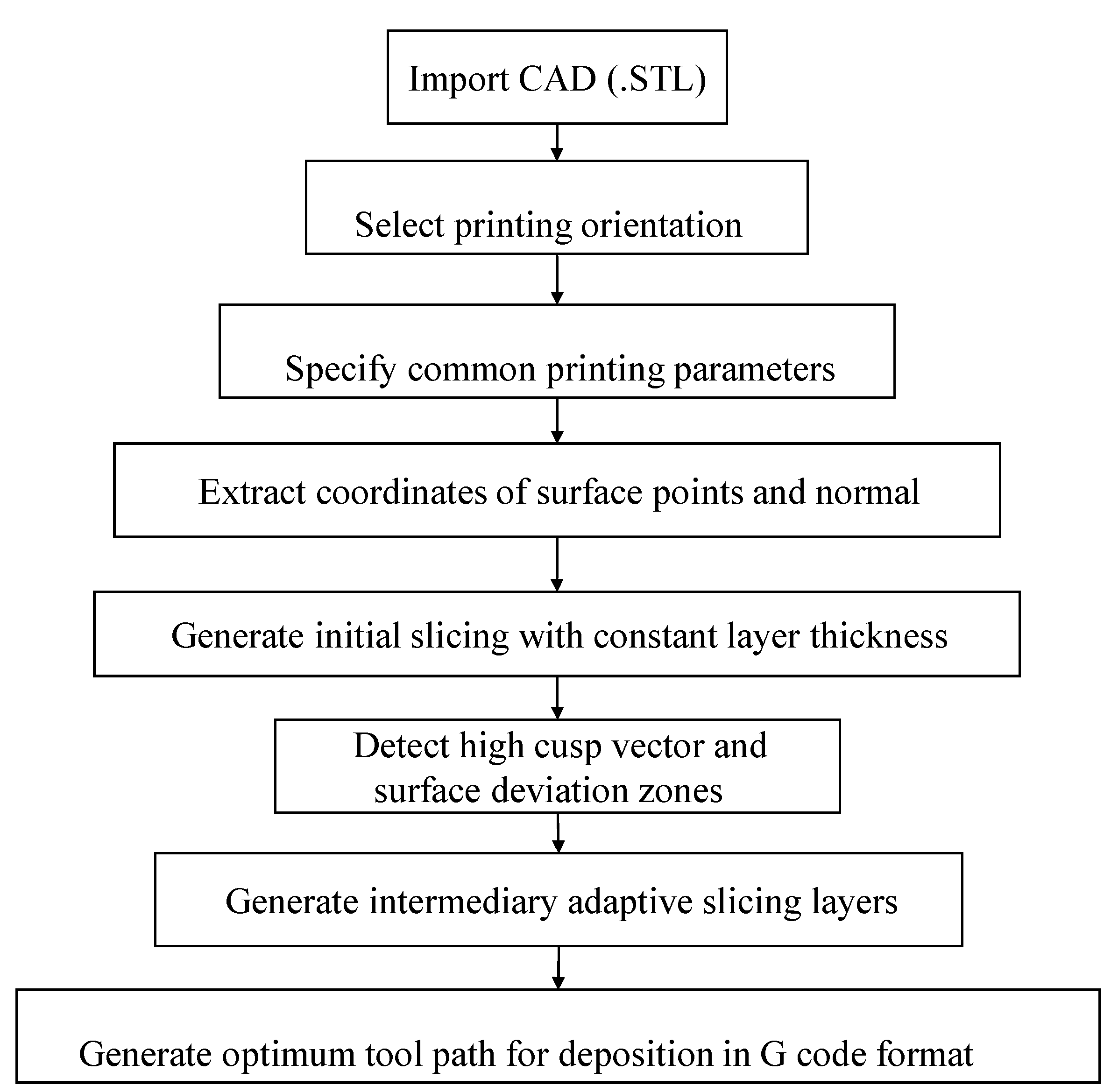
4.1. File Preparation

Firstly, the STL file is read in ASCII or a binary format. The designed MATLAB code processes STL files by determining their format and invoking corresponding functions. It opens the specified file in read-only mode and reads the first 84 bytes to inspect the header and distinguish ASCII from binary format. File information is retrieved using the ‘dir’ function, and the number of facets is determined. The code checks if the file size matches that of a binary STL file and proceeds accordingly, calling either the ‘read_binary_file’ or ‘read_ascii_file’ function for processing. STL data are saved into different matrices as the STL model is composed of different facets, normal vectors, and vertices. At the beginning, the algorithm analyses the data to ensure clearness of construction errors, as the loop of points is totally joined or the existence of three segments for each facet. Then, the normal direction of each facet is used to conclude which side of the facet constitutes the inside of the part (material existence) to be made and which side encloses the space. After reading the STL file, the subsequent step involves orienting the part based on the chosen build orientation. The orientation parameter is preassigned by the user, specifying the printing axis among the axes of the CAD part reference system, with the option to rotate the part 360 degrees around this axis. This selected orientation determines the deposition plane according to the chosen axis. While the paper primarily focuses on the effects of adaptive slicing on part dimensional accuracy, it is worth noting that the chosen build orientation affects the dimensional accuracy of the produced part [37], the mechanical proprieties [27], and the manufacturing time and cost [38].

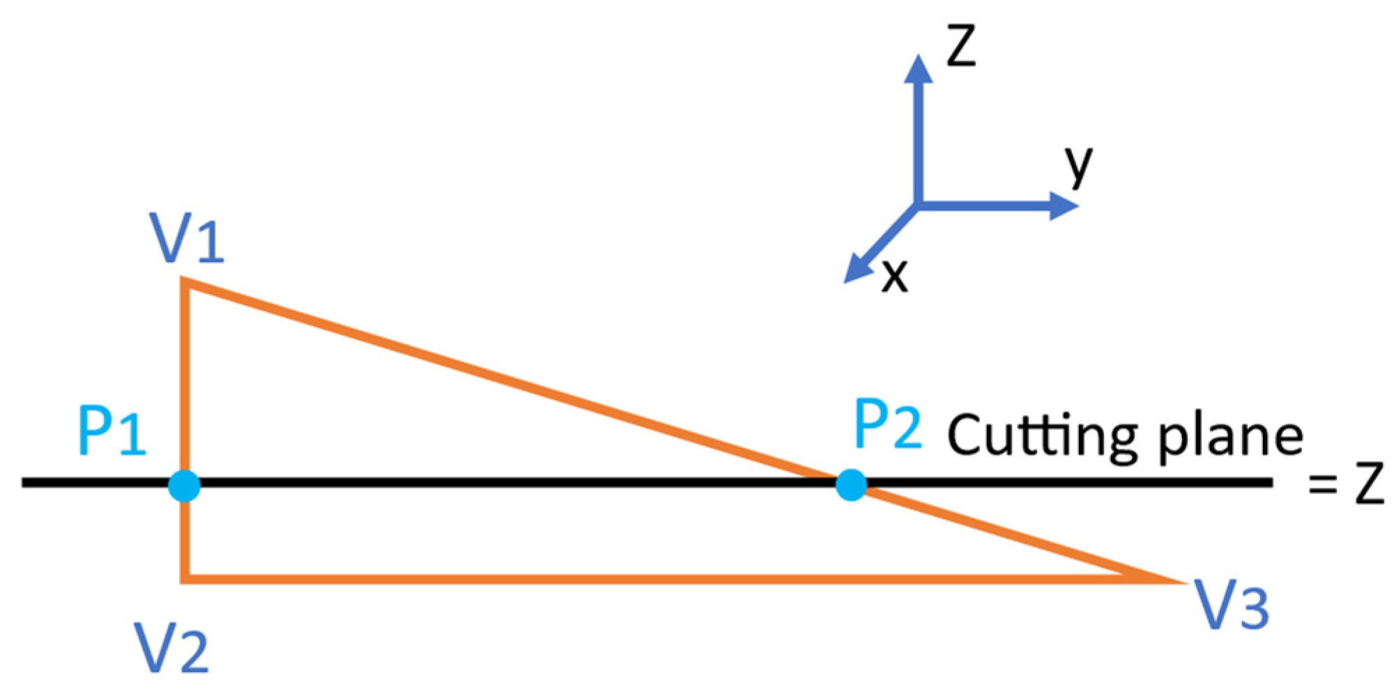
4.2. Extraction of Points Resulting from Facet Intersection

The algorithm recognizes the intersection points between the slicing planes and facets that are equitably distanced as a common step to proceed for the standard slicing or the adaptive slicing. In the workpiece coordinates system (X, Y, Z), let F be the facet intersecting the slicing plane Sp, V1(x1, y1, z1), V2(X2, Y2, Z2) and V3(X3, Y3, Z3) be the facet vertices, and N(Xn, Yn, Zn) be the facet normal vector. The identification of the above facet features is required for the graphical visualization of the STL file. For each layer, each facet in the STL model surface is analyzed to verify its intersection within the slicing plane. As a case of intersection between the Sp and F, two of the F-vertices are located above Sp, and the third is below Sp. This case is highlighted in Figure 5 and represented by Equation (1), such that z is the z-coordinate of the slicing plane.
z 1 > z ,   z 2 < z ,   a n d   ( z 3 < z )
The different intersection cases between Sp and F are illustrated in Figure 6. In fact, ten different positional relationships exist and are determined according to the Z coordinate of Sp. Those cases are listed below (Table 2).
Once all the Fs are checked, the resulting points, as P1 and P2 in Figure 5, are joined to represent lines that are sorted in a start-to-end fashion to create the path of the printer in each layer.

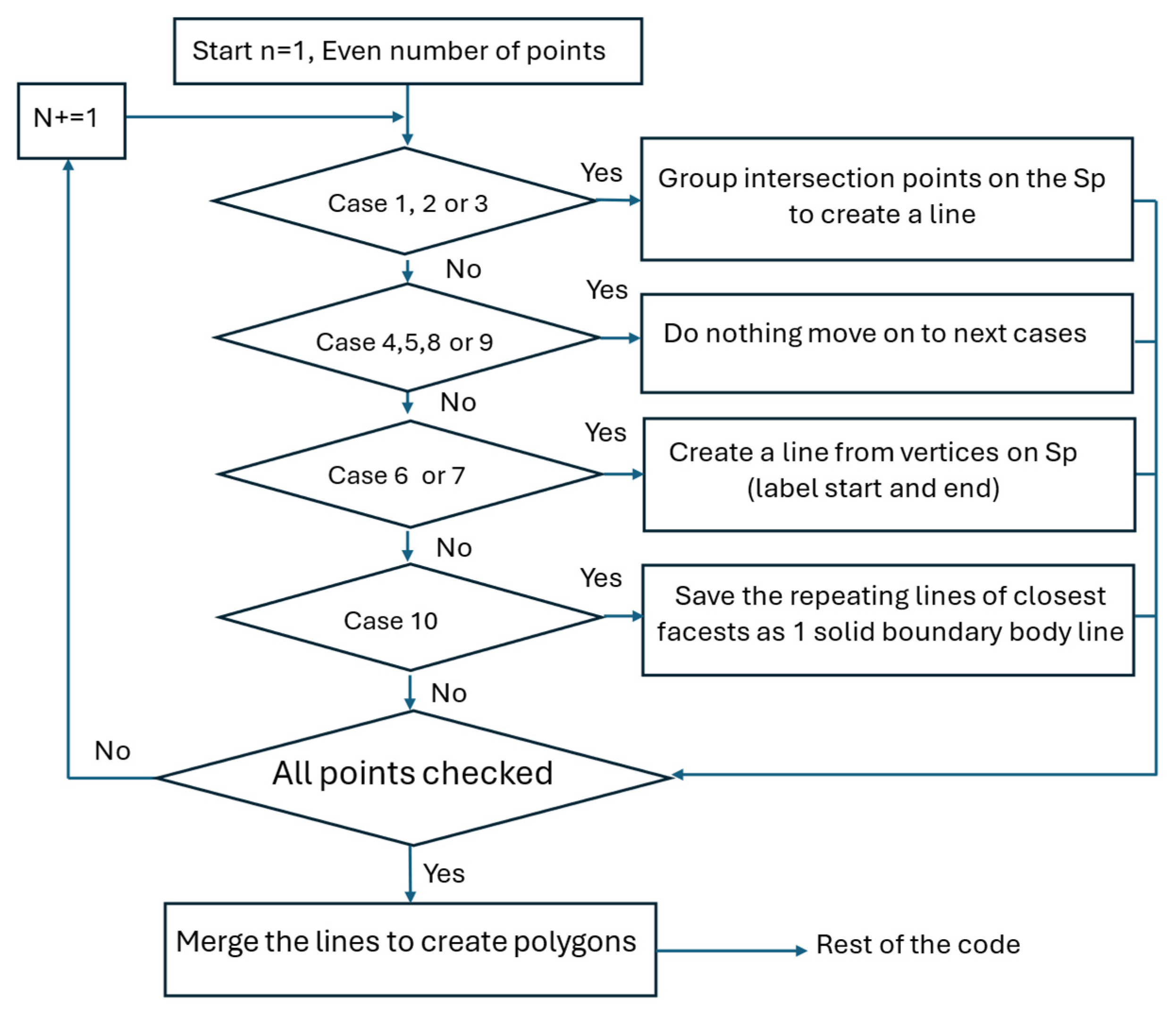
4.3. Polygon Creation

The output resulting from the facet intersection algorithm is the input data used to generate lines of one slice with given z values (layer height). These lines may be connected to form polygons that form a slice (layer). The polygons are two-dimensional (2D) contours that are composed of straight lines defining the hatch path boundary whose generation is essential for improving the surface quality and minimizing the manufacturing time. In fact, after obtaining the coordinates of vertex pairs P1 and P2, the algorithm proceeds to join these pairs to obtain the outline of the polygons that shape the new slice to be inserted between two slices. The flow chart of the polygon creation algorithm is presented in Figure 7. The algorithm recognizes the facet segments formed by the closest vertices to each other and their intersection points with the slicing plane. These points are combined to create a line, which is eventually associated with the other intersection points to form a polygon. Polygons represent either ‘holes’ (free of material) or ‘fills’ (shells or skins of objects). In fact, if a polygon is located inside a second one, then the insider is identified as a ‘hole’ polygon and the outer is considered a ‘fill’ polygon. Next, the algorithm of raster pattern generation will avoid generating a tool path inside the hole polygon.
A complete set of polygons is obtained once all the lines are concatenated to obtain closed polygon loops (vertices merging).

4.4. Layer Thickness Determination

During the preceding step of extracting intersection points, the feature contours defined in the CAD model as face loops are identified, sorted based on the slicing direction, and then stored as a point set for subsequent consideration in the raster creation process. These feature points subdivide the CAD model into portions along the slicing direction, usually the z-direction. The previously described steps are not enough to create the new adaptive slices corresponding to the maximum curvature zones and features. Meanwhile, the cusp height parameter enables the local evaluation of the surface quality, i.e., at a triangulation point of the slice level and relatively to the surface of the 3D printed part [39]. In this paper, the major technological requirements along the developed method are based specifically on the 3D printer capability and limitations. In the developed algorithm, the surface deviation threshold is designated, as well as the printer’s minimum possible layer thickness. These parameters are introduced among the algorithm inputs. A relative area or surface deviation threshold   δ is defined, allowing the consideration of the local geometry complexity, thickness, and the curvature of the CAD surface along the slicing direction without the need for a CAD model as expressed in Equation (2). The surface deviation, alongside the cusp height α, is integrated into the dimensional error calculation as a quantification parameter of the undesirable staircase effect on each layer’s surface. Setting a predefined threshold for surface deviation and a range for cusp height allows the control and the minimization of the undesirable staircase effect on the dimensional errors. In the proposed algorithm, the cusp height continues to be used as a parameter for determining overhang angles. As the overhang angle is directly linked to the cusp height vector, the refinement of the support structure results may be controlled by the choice of the cusp vector height. Meanwhile setting a low value of the surface deviation may lead to the creation of low-thickness layers that surpass the FFF printer’s capabilities. To avoid manufacturing issues such as empty layers or material over-deposing, a minimum layer thickness (threshold) T h m i n should be predefined. Otherwise, setting a high value of the surface deviation may lead to create a high-thickness layer that transpasses the FFF printer capabilities or exceeds the part’s predefined tolerances in some zones of the part. Thus, a maximum layer thickness T h m a x should be predefined. In Equation (2), S i and S i + 1 are two flat surface areas of two consecutive layers. The index is derived from the analytic detection method of the maximum curvature suggested in [33]. An adaptive slicing algorithm is applied to each slice with five pre-specified thresholds, such as maximum relative area deviation δ ,   minimum layer thickness T h m i n , maximum layer thickness T h m a x , minimum cusp height C m i n , and maximum cusp height C m a x .
S i S i + 1   S i + 1   δ
Let Z k   and Z k + 1 are the lower and upper Z-coordinates of a given layer, Th is the layer thickness, and δ k the corresponding relative area deviation. The adaptative slicing algorithm inserts n layers according to Equation (3).
I f   δ k > δ   a n d   ( T h m i n < T h T h m a x ) ,   t h e n   T h n e w = Z k + 1 Z k 2 n

4.5. Generation of the Raster Pattern

Using layers successfully acquired from intersection points and polygons, pattern lines are created, representing toolpaths. The filling type and toolpath affect the fabrication time and quality of final products. The user decision could be based on the functionality, the mechanical constraints, and the stress repartition on the part to guarantee the maximum mechanical resistance. For example, while having a major tensile stress applied to the part, the raster angle should be chosen in the way to provide the maximum stress resistance along the effort repartition direction. The generated pattern respects the user-specified overlapping rate by considering the resulting gap, which is the distance between the neighboring fill lines. The infill function plays a critical role in creating the inner structure of the part, ensuring its structural integrity. It must strike a balance between maximizing stiffness and minimizing manufacturing time.
A sub-algorithm to generate, plot, and display the trajectory describing the toolpaths is developed using MATLAB software. The sub-algorithm inputs are point coordinates belonging to each slicing plane, the positions of these planes, and the layer thickness of each slice. The points are joined along the trajectory based on predefined printing parameters such as the raster angle, the nozzle speed, and the layer thickness. Each trajectory is joined to form a full printable layer. Then, an incrementation is established along the printing orientation axis until the full generation of the toolpath, which will be plotted and displayed as an input of the algorithm.
Next, a CAM code is created using the standard G-code instructions. The code architecture consists of three parts: a start, layer information, and an end. The code programming is automated by a development MATLAB algorithm. The code takes the user’s preferences as inputs to generate a G-code usable by any type of FFF 3D printer.

5. Case Study

In the case study, the two-part designs are selected to investigate the previously developed method. The first part, corresponding to “Design A”, is a bracket containing functional features such as holes, and planar and cylindrical surfaces as shown below with its dimensioning in mm (Figure 8). The second part, corresponding to “Design B”, is a parallelepiped containing functional features such as rectangular and cylindrical holes as shown below with its dimensioning in mm (Figure 8). In Figure 8, t1-t8, L-L3, W-W3, and Cyl-Cyl3 represent the dimensional tolerances of the two parts. The objective is to assign specific feature tolerances in the part drawing rather than applying a general tolerance to all features. This underscores the significance of tolerances as a means of communication support between the design, manufacturing, and inspection phases. These parts have been chosen due to their critical functional features (holes, curves) knowing that the dimensional error could dramatically affect the parts’ function and assemblability. The complexity of the parts has been calculated using the algorithm of Ben Amor et al. [40]. The complexity index is calculated as the average of five different complexity metrics. The part with Design A is more complex than the part with Design B with a complexity rate equal to C = 6.9 for part A compared to C = 5.55 for Part B. The developed methods have been applied to both parts to verify the effectiveness of improving the dimensional defects. Even though more complex parts may be subject to future works. For each of the two selected parts, two prototypes of the same 3D model are 3D printed to evaluate the impacts of the adaptative slicing method on tolerances. The first is fabricated by conventional slicing (the non-optimized parts are called A1 and B1 for Designs A and B, respectively). The second is produced by applying adaptive slicing (the optimized parts are called A2 and B2 for Design A and B, respectively). Consequently, a comparison between the two parts will be investigated to evaluate the reliability of the proposed method.
After reading the STL file of the binary type, the rotate model function is called to orient the STL file along the X, Y, or Z axes to select the building orientation (Figure 9). The function enables the selection of the building orientation to minimize the support volume and increase the printing quality of circular features. In fact, for the first studied case, a rotation of −90° around the X-axis allows for decreasing the support volume and improves the dimensional accuracy of the two circular cylinders with 12.8 mm and 5.4 mm radius. To highlight the impact of adaptive slicing on feature quality, the configuration with a rotation angle of 0° is chosen to be printed. In the conventional slicing method, the constant layer thickness is 0.2 mm. For the second studied case, the part is oriented along the minimal height corresponding to 60 mm. According to this criteria, two directions are possible (the part´s nominal dimensions are 60 × 60 × 80 mm). The used adaptative slicing parameters are maximum relative area deviation δ = 4.5 % ,   minimum layer thickness, T h m i n = 0.05   mm, maximum layer thickness T h m a x = 0.2   mm, and cusp height range [ T h m i n , T h m a x ] . To verify the effectiveness of the proposed method for parts with support structures, the test part (model A) is manufactured without a support structure and the test part (model B) with a support structure in the holes (rectangular and cylindrical), are designed and printed using both of the standard slicing method and the proposed adaptive slicing method. The dimensional accuracy of the printed part is then measured and compared between the two methods. The results show the added value of the adaptive slicing method with (model A) and without (model B) the existence of support material.

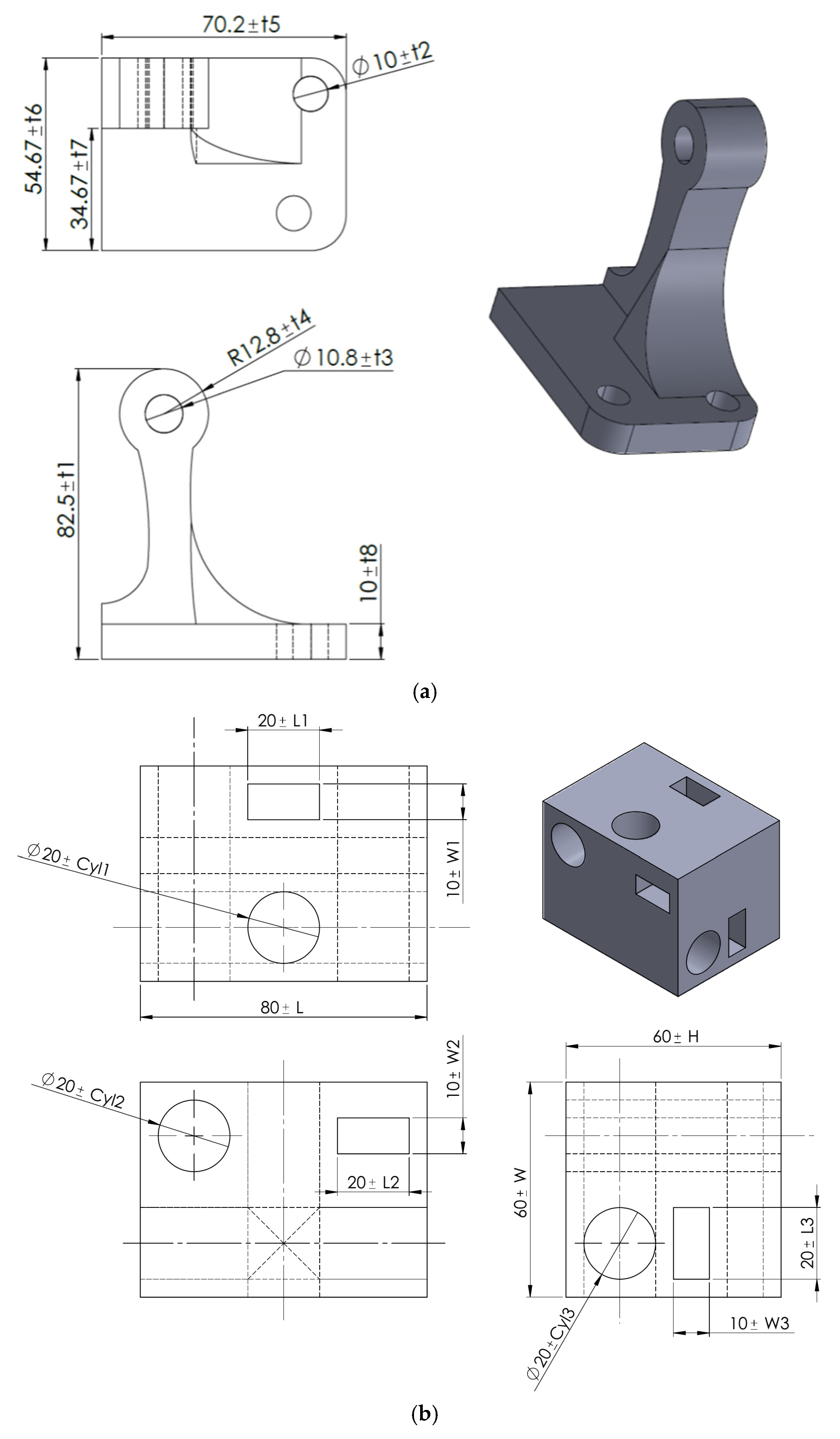
5.1. Design and Manufacturing Results

Figure 10 shows the results of the two studied models slicing using conventional and proposed methods. The plot of the toolpaths in MATLAB allows the visual detection of the stair-stepping effect. This effect varies according to the layer thickness in the case of toolpaths generated by the proposed approach. The layer thickness ranges from 0.2 mm to 0.05 mm for a nozzle diameter of 0.4 mm. The part surfaces with high curvatures are sliced with thin layers, although the layer thickness is kept constant in the uniform regions.
The above results are encouraging for the improved quality of functional features with complex shapes. Minimizing the layer height tends to decrease dimensional errors compared to the standard sliced models, but the main challenge is to find a compromise between enhancing the feature quality and reducing the printing time. Indeed, the layer thickness decreases in the regions that contain functional features with high curvatures, whereas they become more condensed and consequently more precise in these regions.
During standard linear slicing of the two models, the program keeps the same thickness. The gap between the layers during slicing remains constant regardless of the characteristics of the proposed model, which then allows the generation of G-code to print the parts.
Regarding computational time, the hardware configuration employed for algorithm implementation comprises a CPU (up to 4 GHz, 8 MB cache, RAM: 16 GB memory-2666 MHz) and a graphics card (4 GB GDDR5 memory, dedicated frequency 1485 MHz). Table 3 illustrates the processing time for the two designs utilizing the two slicing methods. In both cases, the processing time increases by approximately 2%.
Parts A1 and A2 are manufactured using a Rise3D N2 printer with PLA material. Meanwhile, parts B1 and B2 are printed using an Ultimaker 2+ printer with PLA material (Figure 11). As shown in Figure 11, parts A1 and B1 are printed using the conventional slicing method, and parts A2 and B2 are fabricated using adaptative slicing. For each design A or B, the manufacturing parameters are the same, except for the layer thickness as shown in Table 4 and Table 5. For Design A, the number of layers in part A2 is greater than that of part A1 increasing the printing time and decreasing the weight of the used raw material. Meanwhile, for the second studied case (B), the number of layers in part B2 is greater than in part B1 in increasing the printing time, and increasing the weight of the used raw material insignificantly (Table 5).

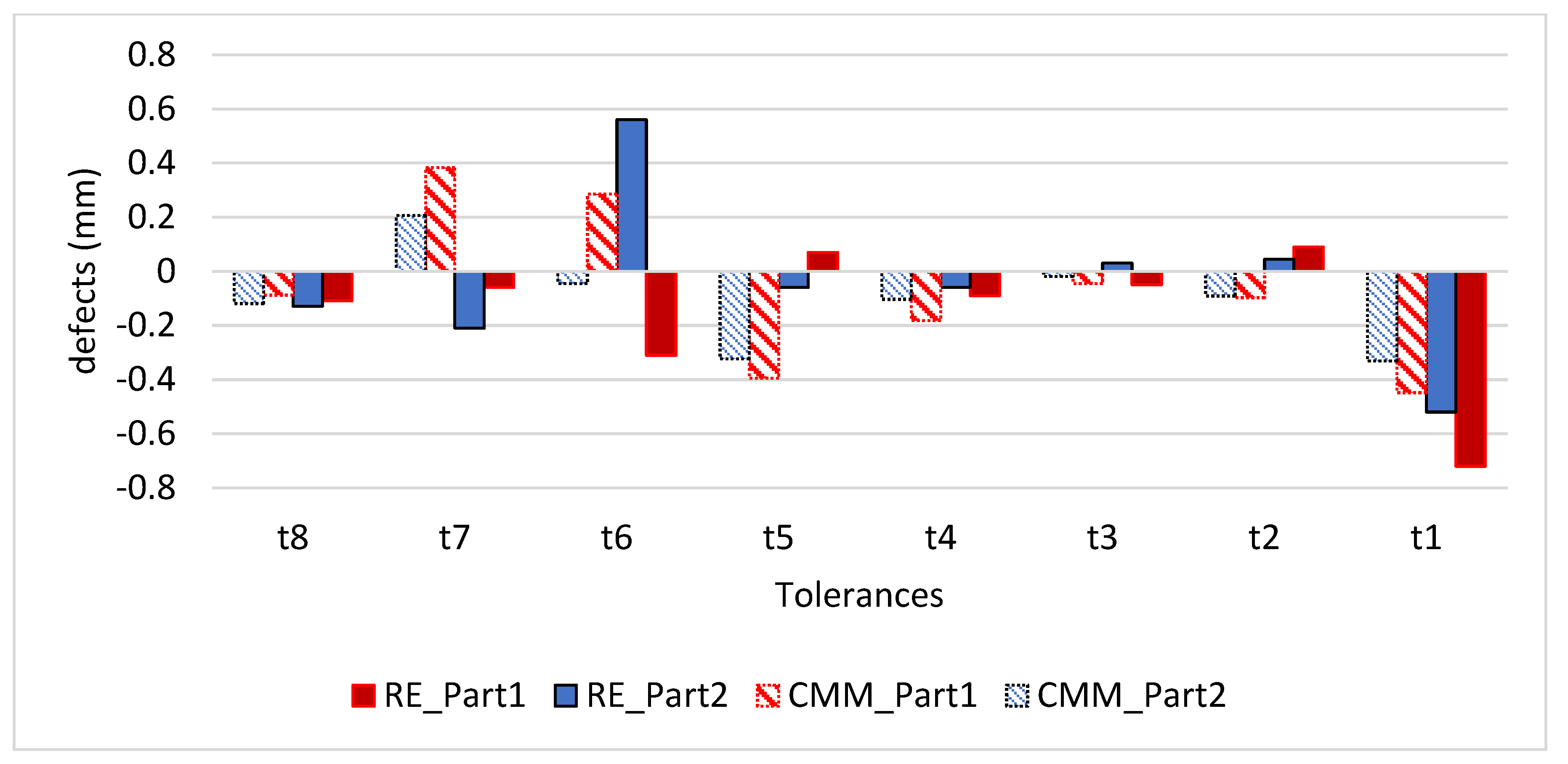
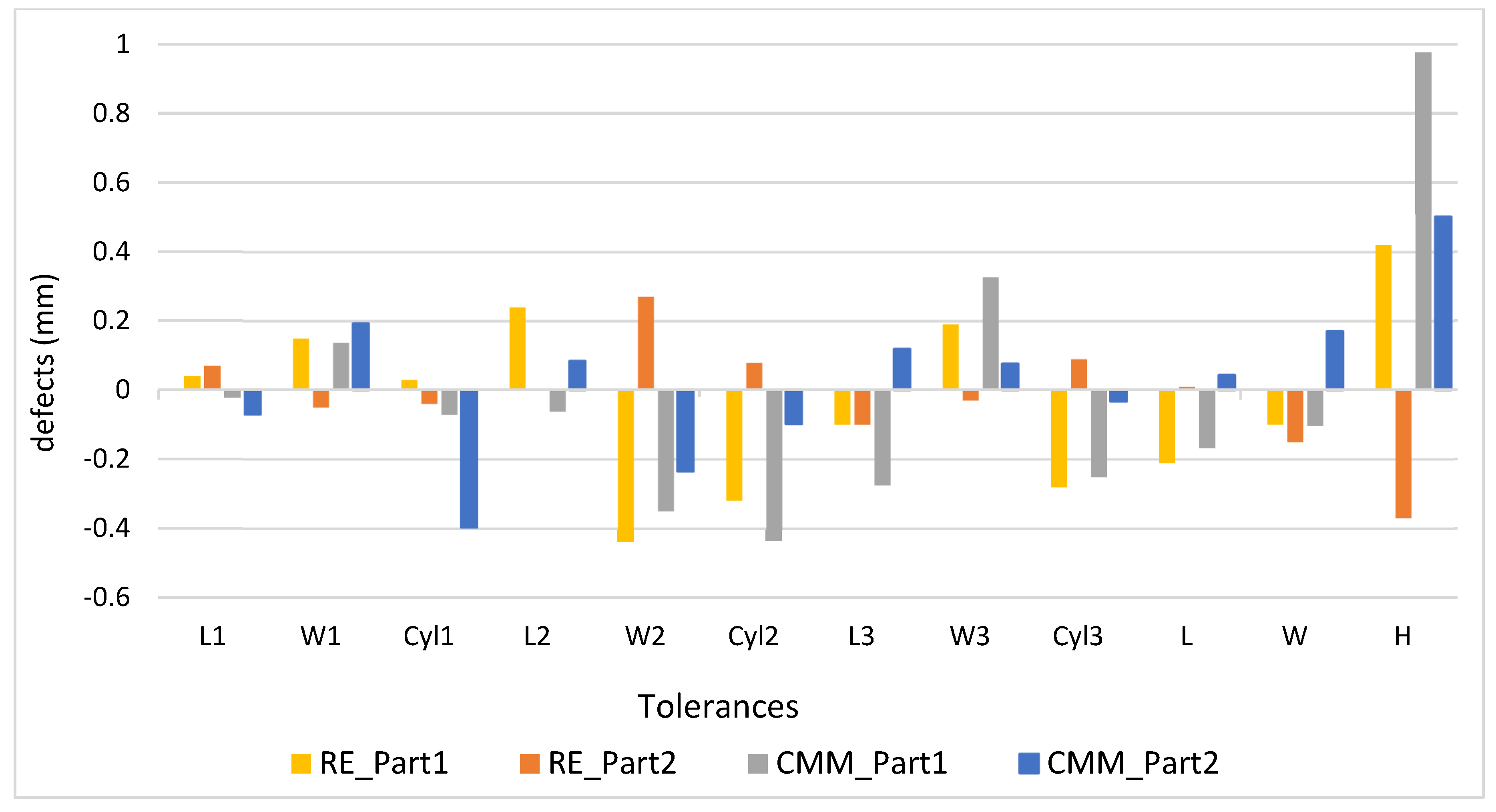
5.2. Measurement Results

In this study, two different inspection methods are used to validate the proposed method (Figure 12). The first method is the reverse engineering (RE) approach based on the data extraction from the rebuilt model. The RE is processed using EINSCAN PRO + scanner with an accuracy of 0.04 mm. This scanner is manufactured by SHINING 3D headquartered in Hangzhou, China. The scanning process is repeated three times and the results are combined through the Scanner software to guarantee a better precision and greater density of the points cloud. The input data are the scanned cloud points of the two manufactured parts.
The second method uses a CE JOHANSSON coordinate-measuring (CMM) machine with an (MPEE) accuracy of 3 + 4 L/1000. Each feature has been measured five times and an average measure is calculated automatically via the machine software. The dimensional measurement errors and accuracy gains for both Design A and Design B are presented in Table 6 and Table 7, respectively, while the corresponding graphical representations are illustrated in Figure 13 and Figure 14. In these tables and figures, the error values indicate the deviation of the measured dimensions from the nominal dimensions. Using signed error representations instead of absolute values, the analysis allows for a more comprehensive understanding of the impacts of different slicing methods on both dimensional defects and shrinkage behavior.
For the first case study (Design A) with parts A1 and A2, the differences between the measurement results obtained with the two measurement methods present a deviation average of 0.237 mm (standard deviation of 0.208 mm). The deviations are mainly due to the errors during surface reconstruction from the 3D scan in the RE process. For the second studied case (Design B), the deviation average is 0.265 mm (standard deviation of 0.232 mm). However, using the same measurement tool, the resulting dimensions of part A2 are more accurate than A1, except for the tolerances t6 and t7 when measured using the RE technique for Design A. Additionally, using the same measurement tool, the resulting dimensions of B2 are more accurate than those of B1, except for the tolerances L1, W1, and Cyl1 corresponding to dimensions of feature locating in the top and the bottom part faces. The top and bottom faces are not affected by the adaptive slicing optimization because they are perpendicular to the printing direction. The previous results confirm the dimensional enhancement due to the adaptive slicing application.
Cost impact
To explore the developed method and assess its cost implications, we adopt a modified cost model from the approach proposed in [10]. The total manufacturing cost Ct of each part is computed by considering the raw material cost Cr, machine cost Cm, and labor cost Cl (Equation (4)). The preprocessing and machine setup times are assumed to be consistent across all parts (14.52 min). Consequently, labor costs remain uniform for all parts, as the labor tasks are confined to preprocessing and machine setup. The cost comparisons will be based on printing costs Cp, representing the sum of machine and raw material costs.
Given the equipment purchase cost Ce, the cost of annual equipment depreciation Cde and the cost of annual machine maintenance Cma can be defined by Equation (5). Given the annual working hours T and one possible part to build per platform, the machine cost per hour Cmh is defined by Equation (6). The machine cost is calculated by multiplying the machine cost per hour by the printing time of each part (Table 3). Then, the found result is added to the material printed cost Cr (Table 8). For Design B, the printing costs are USD 9.23 for the non-optimized part versus USD 11.77 for the optimized part. The cost loss of 21.6%. For Design A, printing cost results are USD 3.91 for the non-optimized part versus USD 3.74 for the optimized part. The cost gain is 4.3%.
C t = C r + C m + C l = C p + C l
C d e = C e 5   a n d   C m a = C e 8
C m h = C d e + C m a T

6. Discussion

In the literature, the poor dimensional accuracy of rectangular 3D printed shapes results from fewer layer numbers [41,42,43]. Low dimensional precision results from more layers when interlayer distortion and thermal cycles (non-uniform temperature gradient between bonded layers) become prominent factors [43,44]. This verdict is confirmed in the case of the 10 mm dimension (with tolerance t8) of the prismatic portion of the part and visually observable on the planar surface of Part A2 due to low infill density predefined to identify the slicing weakness and highlights (Figure 11). In [42], the impacts of layer thickness on the dimensional accuracy of dog-bone specimens, as a non-rectangular shape, are investigated. However, the dimensional measurements were limited to the part thickness and width characterizing a rectangular profile.
For Design A, the proposed algorithm improves the accuracy of features with high curvature, as the cylindrical features constrained to the tolerances t1, t3, and t4, i.e., t1, t3, and t4 achieve accuracy gains of 0.24%, 0.37%, and 0.24% using RE, and has accuracy gains 0.14%, 0.48%, and 0.62% using CMM, respectively. For the second studied case, the proposed algorithm improves the accuracy of features with high curvature along the contour surfaces (except the top and the bottom faces), as the cylindrical features constrained to the tolerances cyl2, cyl4, cyl5, and cyl6, i.e., which achieve accuracy gains of 1.69%, 0.55%, 1.21%, and 0.95% using RE, and has accuracy gains of 2.20%, 1.18%, 1.66% and 0.37% using CMM, respectively.
The reduction of the stair-stepping effect located in surfaces with high curvature, the dimensional accuracy improvement spread over the other part dimensions. Indeed, regarding the dimensional accuracy between the two prototypes, for the first case study, the proposed method allows gain averages of 0.1% and 0.3% using RE and CMM processes, respectively. For the second case study, the gain averages are 0.58% and 0.76% using RE and CMM processes. These benefits are accompanied by a marginal increase in computational times of 2%. Additionally, the adaptive slicing method resulted in a 5.2% increase in printing time for Design A and a 77% increase for Design B. The significant increase in printing time for Design A can be attributed to the higher number of layers resulting from the presence of six features along all three printing axes. Regarding the total part height, the heat shrinkage effects are reduced along the printing direction for both parts. For Design A, the proposed slicing technique leads to an economical gain. Hence, the proposed slicing method is suitable for solving specific FFF shortcomings and enhancing dimensional accuracy as it consists of adapting the slicing pitch to reduce the stair-stepping effect. The proposed adaptive slicing algorithm could be further enhanced by considering the following roadmaps:
  • The improvement in the algorithm efficiency in terms of printing time could be achieved by carefully selecting the range of layer thickness. The outcomes of the study could inform this selection by employing a multi-optimization algorithm to achieve a balanced solution between required the dimensional accuracy and printing time.
  • The algorithm serves as a guideline for considering dimensional tolerances during the slicing process, presenting a new challenge for parts including features with different tolerance values in the part drawing. The proposed algorithm smoothly accommodates the allocation of specific values of the cusp height and surface deviation threshold to layers containing features according to their assigned tolerance values.
  • In addition to layer thickness, several FFF parameters, such as build orientation, printing speed, nozzle temperature, and pressure conditions, significantly influence part dimensional accuracy. Moreover, achieving enhanced dimensional accuracy must also align with the desired mechanical properties and surface quality of the printed functional parts. Therefore, further investigations employing multi-objective optimization approaches are necessary to address these interconnected requirements simultaneously.
  • Zones with lower material density are observed when having many low-thickness layers gathered in the adaptive slicing part. This phenomenon may lead to diminished mechanical properties due to inadequate material adhesion. Algorithm inputs such as cusp height, surface deviation, and layer thickness thresholds should be determined through a multi-optimization approach that considers dimensional accuracy, mechanical properties, and build orientation. The development of a multi-criteria decision model (MCDM) that articulates product requirements concerning manufacturing cost, part accuracy, quality, and mechanical properties will enhance the durability of the product.

7. Conclusions

This study proposed an adaptative slicing method for dimensional accuracy improvement. After the data extraction from the STL file, points resulting from the intersection between the initial STL mesh and the slicing plane of the original layer are detected, allowing the reduction of layer thickness according to the surface local curvature. The method evaluation was investigated through two studied cases where two prototypes of each of the two CAD models were 3D printed using both the standard and the developed slicing methods. Both the RE technique and CMM were used for dimensional measurements. The main novelties presented through this work are the adaptive slicing method based on the surface deviation as a more precise inspection parameter beside the FFF printer capabilities presented by the minimum and the maximum possible layer thickness. These novelties are proven to be efficient for meeting the paper’s purpose in two different case studies. The main work contributions can be summarized as follows:
  • The result analysis demonstrates the promising capability of the slicing approach to improve the dimensional accuracy of FFF parts. Compared to standard slicing, the proposed method led to enhancements in dimensional accuracy, with average gains of 0.1% and 0.3% observed using RE and CMM processes, respectively. Similarly, in the second case study, average gains of 0.58% and 0.76% were achieved using RE and CMM processes.
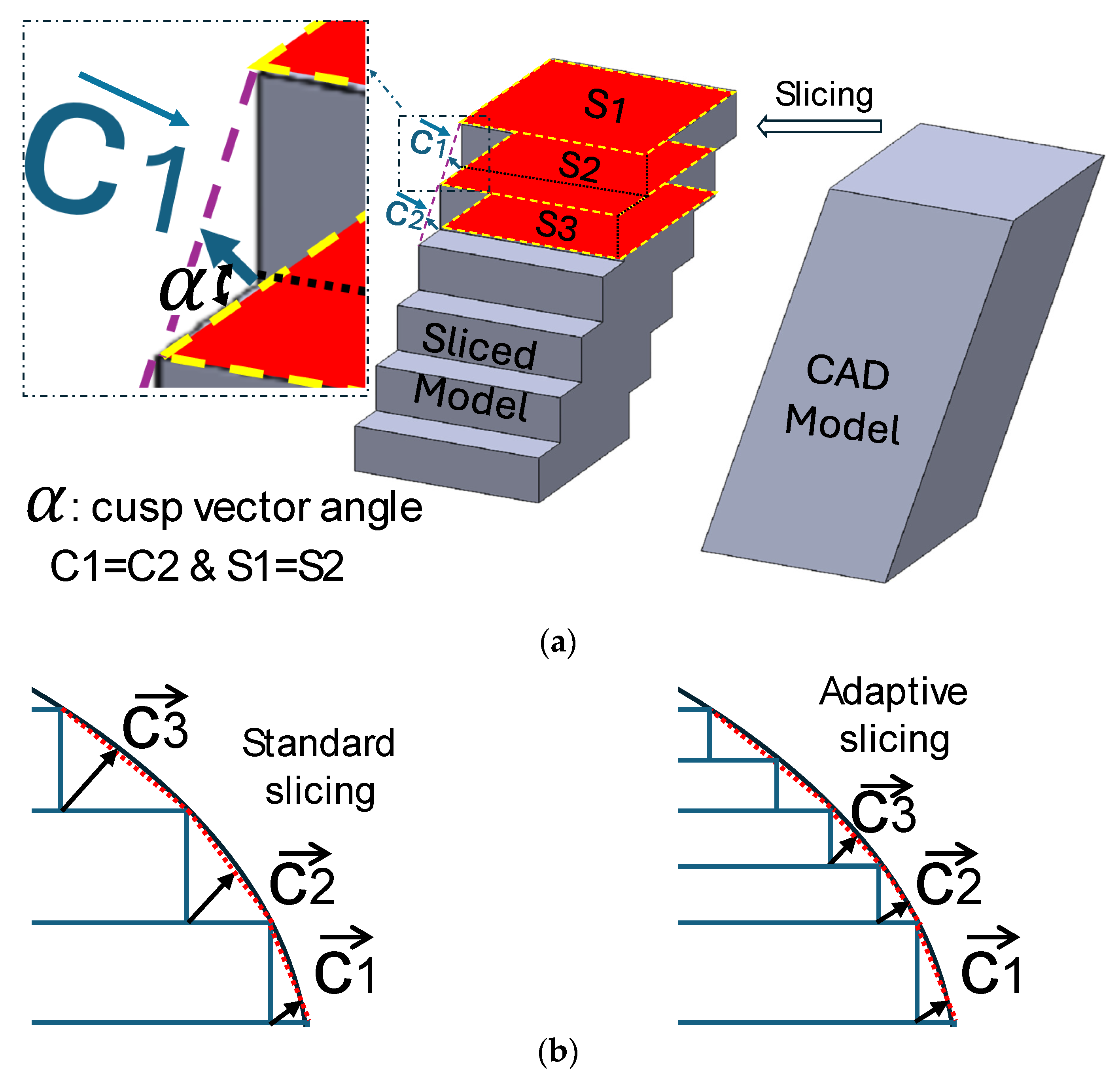
  • The method effectively reduces the stair-stepping effect on curved shapes and minimizes heat shrinkage along the printing direction. It is particularly effective in improving the dimensional accuracy of features with highly curved shapes compared to linear contours.
The enhancement in dimensional accuracy was accompanied by a minor increase in computational time (2%) and a proportional rise in print time (5.2–77%) according to the design complexity. The proposed method can yield economic benefits depending on the number of features present in the part.
However, some limitations of the proposed method are acknowledged and potential areas for future research are suggested. For example, the authors note that the proposed algorithm may not be suitable for all types of geometries and materials and that further studies are needed to evaluate its performance under different conditions. Additionally, incorporating real-time feedback and control mechanisms could further improve the accuracy and efficiency of the FFF process. Further investigations on the effects of the suggested slicing method on the material properties, roughness, and geometrical tolerances are challenging tasks for the improvement of FFF process reliability. The support material effect has not been taken into consideration since the printing orientation for the two case studies is selected as the 0-degree rotation case. However, the support material integration effect should be investigated in further work.

Author Contributions

Conceptualization, A.E. (Ahmed Elayeb), B.L. and M.T.; methodology, A.E. (Ahmed Elayeb) and M.T.; software, A.E. (Ahmed Elayeb) and M.T.; validation, A.E. (Ahmed Elayeb) and M.T.; formal analysis, A.E. (Ahmed Elayeb); investigation, A.E. (Ahmed Elayeb), B.L. and M.T. and; resources, A.E. (Ahmed Elayeb) and M.T.; data curation, A.E. (Ahmed Elayeb), M.T. and F.Z.; writing—original draft preparation, A.E. (Ahmed Elayeb), M.T. and B.L.; writing—review and editing, A.E. (Ahmed Elayeb), M.T., A.E. (Ameni Eltaief), B.L. and F.Z.; visualization, A.E. (Ahmed Elayeb) and M.T.; supervision, B.L. and M.T.; project administration, M.T. and B.L. All authors have read and agreed to the published version of the manuscript.

Funding

This research received no external funding.

Data Availability Statement

Data are contained within the article.

Conflicts of Interest

The authors declare no conflicts of interest.

References

  1. Klahn, C.; Leutenecker, B.; Meboldt, M. Design for Additive Manufacturing—Supporting the Substitution of Components in Series Products. Procedia CIRP 2014, 21, 138–143. [Google Scholar] [CrossRef]
  2. Emmelmann, C.; Kranz, J.; Herzog, D.; Wycisk, E. Laser Technology in Biomimetics; Springer: Berlin/Heidelberg, Germany, 2013. [Google Scholar] [CrossRef]
  3. Shi, S.; Jiang, Y.; Ren, H.; Deng, S.; Sun, J.; Cheng, F.; Jing, J.; Chen, Y. 3D-Printed Carbon-Based Conformal Electromagnetic Interference Shielding Module for Integrated Electronics. Nano-Micro Lett. 2024, 16, 85. [Google Scholar] [CrossRef] [PubMed]
  4. Colorado, H.A.; Velásquez, E.I.G.; Monteiro, S.N. Sustainability of Additive Manufacturing: The Circular Economy of Materials and Environmental Perspectives. J. Mater. Res. Technol. 2020, 9, 8221–8234. [Google Scholar] [CrossRef]
  5. Ngo, T.D.; Kashani, A.; Imbalzano, G.; Nguyen, K.T.Q.; Hui, D. Additive Manufacturing (3D Printing): A Review of Materials, Methods, Applications and Challenges. Compos. Part B Eng. 2018, 143, 172–196. [Google Scholar] [CrossRef]
  6. Dey, A.; Yodo, N. A Systematic Survey of FDM Process Parameter Optimization and Their Influence on Part Characteristics. J. Manuf. Mater. Process. 2019, 3, 64. [Google Scholar] [CrossRef]
  7. Solomon, I.J.; Sevvel, P.; Gunasekaran, J. A Review on the Various Processing Parameters in FDM. Mater. Today Proc. 2020, 37, 509–514. [Google Scholar] [CrossRef]
  8. Wang, Y.-C.; Chen, T.; Lin, Y.-C. 3D Printer Selection for Aircraft Component Manufacturing Using a Nonlinear FGM and Dependency-Considered Fuzzy VIKOR Approach. Aerospace 2023, 10, 591. [Google Scholar] [CrossRef]
  9. Sharma, A.; Rai, A. Fused Deposition Modelling (FDM) Based 3D & 4D Printing: A State of Art Review. Mater. Today Proc. 2022, 62, 367–372. [Google Scholar] [CrossRef]
  10. Tlija, M.; Al-Tamimi, A.A. Combined Manufacturing and Cost Complexity Scores-Based Process Selection for Hybrid Manufacturing. Proc. Inst. Mech. Eng. Part B J. Eng. Manuf. 2023, 237, 1473–1484. [Google Scholar] [CrossRef]
  11. Angrish, A. A Critical Analysis of Additive Manufacturing Technologies for Aerospace Applications. In Proceedings of the 2014 IEEE Aerospace Conference, Big Sky, MT, USA; 2014; pp. 1–6. [Google Scholar] [CrossRef]
  12. Sun, B.; Ma, Q.; Wang, X.; Liu, J.; Rejab, M.R.M. Additive Manufacturing in Medical Applications: A Brief Review. IOP Conf. Ser. Mater. Sci. Eng. 2021, 1078, 012007. [Google Scholar] [CrossRef]
  13. Carvalho, J.R.G.; Conde, G.; Antonioli, M.L.; Santana, C.H.; Littiere, T.O.; Dias, P.P.; Chinelatto, M.A.; Canola, P.A.; Zara, F.J.; Ferraz, G.C. Long-Term Evaluation of Poly(Lactic Acid) (PLA) Implants in a Horse: An Experimental Pilot Study. Molecules 2021, 26, 7224. [Google Scholar] [CrossRef]
  14. Alrasheedi, N.H.; Tlija, M.; Elloumi, N.; Louhichi, B. A Critical Review of 3D Printed Orthoses towards Workflow Implementation in the Clinical Practice. J. Eng. Res. 2024, in press. [Google Scholar] [CrossRef]
  15. Schuh, G.; Bergweiler, G.; Fiedler, F.; Bickendorf, P.; Schumacher, P. Small Series Production and Geometric Analysis of Sheet Metal Car Body Parts Using Forming Tools Made of Fused Filament Fabricated PLA. In Proceedings of the 2020 IEEE International Conference on Industrial Engineering and Engineering Management (IEEM), Singapore, 14–17 December 2020; Volume 2020, pp. 156–160. [Google Scholar]
  16. Berni, A.; Borgianni, Y.; Obi, M.; Pradel, P.; Bibb, R. Investigating Perceived Meanings and Scopes of Design for Additive Manufacturing. Proc. Des. Soc. 2021, 1, 1937–1946. [Google Scholar] [CrossRef]
  17. Quan, Z.; Wu, A.; Keefe, M.; Qin, X.; Yu, J.; Suhr, J.; Byun, J.H.; Kim, B.S.; Chou, T.W. Additive Manufacturing of Multi-Directional Preforms for Composites: Opportunities and Challenges. Mater. Today 2015, 18, 503–512. [Google Scholar] [CrossRef]
  18. Tolosa, I.; Garciandía, F.; Zubiri, F.; Zapirain, F.; Esnaola, A. Study of Mechanical Properties of AISI 316 Stainless Steel Processed by “Selective Laser Melting”, Following Different Manufacturing Strategies. Int. J. Adv. Manuf. Technol. 2010, 51, 639–647. [Google Scholar] [CrossRef]
  19. Caulfield, B.; McHugh, P.E.; Lohfeld, S. Dependence of Mechanical Properties of Polyamide Components on Build Parameters in the SLS Process. J. Mater. Process. Technol. 2007, 182, 477–488. [Google Scholar] [CrossRef]
  20. Mercelis, P.; Kruth, J.P. Residual Stresses in Selective Laser Sintering and Selective Laser Melting. Rapid Prototyp. J. 2006, 12, 254–265. [Google Scholar] [CrossRef]
  21. Lieneke, T.; Denzer, V.; Adam, G.A.O.; Zimmer, D. Dimensional Tolerances for Additive Manufacturing: Experimental Investigation for Fused Deposition Modeling. Procedia CIRP 2016, 43, 286–291. [Google Scholar] [CrossRef]
  22. Zhu, Z.; Anwer, N.; Huang, Q.; Mathieu, L. Machine Learning in Tolerancing for Additive Manufacturing. CIRP Ann. 2018, 67, 157–160. [Google Scholar] [CrossRef]
  23. Calignano, F.; Manfredi, D.; Ambrosio, E.P.; Biamino, S.; Pavese, M.; Fino, P. Direct Fabrication of Joints Based on Direct Metal Laser Sintering in Aluminum and Titanium Alloys. Procedia CIRP 2014, 21, 129–132. [Google Scholar] [CrossRef]
  24. Liu, H.; Liu, L.; Li, D.; Huang, R.; Dai, N. An Approach to Partition Workpiece CAD Model towards 5-Axis Support-Free 3D Printing. Int. J. Adv. Manuf. Technol. 2020, 106, 683–699. [Google Scholar] [CrossRef]
  25. Goguelin, S.; Dhokia, V.; Flynn, J.M. Bayesian Optimisation of Part Orientation in Additive Manufacturing. Int. J. Comput. Integr. Manuf. 2021, 34, 1263–1284. [Google Scholar] [CrossRef]
  26. Angelo, L.D.; Stefano, P.D.; Guardiani, E. Search for the Optimal Build Direction in Additive Manufacturing Technologies: A Review Search for the Optimal Build Direction in Additive Manufacturing Technologies: A Review. J. Manuf. Mater. Process. 2020, 4, 71. [Google Scholar] [CrossRef]
  27. Spišák, E.; Nováková-Marcinčínová, E.; Majerníková, J.; Mulidrán, P.; Nováková-Marcinčínová, Ľ. Experimental and Numerical Study of Printing Strategy Impact on the Mechanical Properties of Sustainable PLA Materials. Polymers 2023, 15, 4639. [Google Scholar] [CrossRef]
  28. Ritter, T.; McNiffe, E.; Higgins, T.; Sam-Daliri, O.; Flanagan, T.; Walls, M.; Ghabezi, P.; Finnegan, W.; Mitchell, S.; Harrison, N.M. Design and Modification of a Material Extrusion 3D Printer to Manufacture Functional Gradient PEEK Components. Polymers 2023, 15, 3825. [Google Scholar] [CrossRef]
  29. O’Connor, H.J.; Dowling, D.P. Evaluation of the Influence of Low Pressure Additive Manufacturing Processing Conditions on Printed Polymer Parts. Addit. Manuf. 2018, 21, 404–412. [Google Scholar] [CrossRef]
  30. Boschetto, A.; Bottini, L. Accuracy Prediction in Fused Deposition Modeling. Int. J. Adv. Manuf. Technol. 2014, 73, 913–928. [Google Scholar] [CrossRef]
  31. Byun, H.S.; Lee, K.H. Determination of Optimal Build Direction in Rapid Prototyping with Variable Slicing. Int. J. Adv. Manuf. Technol. 2006, 28, 307–313. [Google Scholar] [CrossRef]
  32. Al-Tamimi, A.A.; Tlija, M.; Abidi, M.H.; Anis, A.; Abd Elgawad, A.E.E. Material Extrusion of Multi-Polymer Structures Utilizing Design and Shrinkage Behaviors: A Design of Experiment Study. Polymers 2023, 15, 2683. [Google Scholar] [CrossRef] [PubMed]
  33. Zhao, Z.; Laperrière, L. Adaptive Direct Slicing of the Solid Model for Rapid Prototyping. Int. J. Prod. Res. 2000, 38, 69–83. [Google Scholar] [CrossRef]
  34. Di Angelo, L.; Di Stefano, P.; Marzola, A. Surface Quality Prediction in FDM Additive Manufacturing. Int. J. Adv. Manuf. Technol. 2017, 93, 3655–3662. [Google Scholar] [CrossRef]
  35. Angelo, L.D.; Di Stefano, P.; Dolatnezhadsomarin, A.; Guardiani, E.; Khorram, E.; Stefano, P.D. A Reliable Build Orientation Optimization Method in Additive Manufacturing: The Application to FDM Technology. Int. J. Adv. Manuf. Technol. 2020, 108, 263–276. [Google Scholar] [CrossRef]
  36. Shao, M.; Wei, C.; Cui, B.; Li, Y.; Zheng, T. An Adaptive Slicing Approach for Processing STL Massive Data Model in Batches Based on Layer Merging. J. Phys. Conf. Ser. 2021, 1884, 012025. [Google Scholar] [CrossRef]
  37. Elayeb, A.; Korbi, A.; Tlija, M.; Louhichi, B. Optimal Part Orientation in the Additive Manufacturing Process Based on Tolerancing. In Advances in Mechanical Engineering and Mechanics II; Lecture Notes in Mechanical Engineering; Springer: Cham, Switzerland, 2022; pp. 217–225. [Google Scholar]
  38. Tagore, G.R.N.; Anjikar, S.D.; Venu Gopal, A. Multi Objective Optimisation of Build Orientation for Rapid Prototyping with Fused Deposition Modeling (FDM). In Proceedings of the 18th Solid Freeform Fabrication Symposium, Austin, TX, USA, 6–8 August 2007; pp. 246–255. [Google Scholar]
  39. Kulkarni, P.; Dutta, D. An Accurate Slicing Procedure for Layered Manufacturing. Comput. Des. 1996, 28, 683–697. [Google Scholar] [CrossRef]
  40. Ben Amor, S.; Zongo, F.; Eltaief, A.; Maatki, A.; Louhichi, B.; Tahan, A. A New Method to Select Optimal Part Building Orientation for Additive Manufacturing Processes Based on Geometric Complexity and Heat Shrinkage. Prog. Addit. Manuf. 2023, 8, 211–222. [Google Scholar] [CrossRef]
  41. Hyndhavi, D.; Babu, G.R.; Murthy, S.B. Investigation of Dimensional Accuracy and Material Performance in Fused Deposition Modeling. Mater. Today Proc. 2018, 5, 23508–23517. [Google Scholar] [CrossRef]
  42. Hanon, M.M.; Zsidai, L.; Ma, Q. Accuracy Investigation of 3D Printed PLA with Various Process Parameters and Different Colors. Mater. Today Proc. 2021, 42, 3089–3096. [Google Scholar] [CrossRef]
  43. Mohamed, O.A.; Masood, S.H.; Bhowmik, J.L.; Nikzad, M.; Azadmanjiri, J. Effect of Process Parameters on Dynamic Mechanical Performance of FDM PC/ABS Printed Parts Through Design of Experiment. J. Mater. Eng. Perform. 2016, 25, 2922–2935. [Google Scholar] [CrossRef]
  44. Xinhua, L.; Shengpeng, L.; Zhou, L.; Xianhua, Z.; Xiaohu, C.; Zhongbin, W. An Investigation on Distortion of PLA Thin-Plate Part in the FDM Process. Int. J. Adv. Manuf. Technol. 2015, 79, 1117–1126. [Google Scholar] [CrossRef]
Figure 1. (a) Stair-stepping effect; (b) geometrical distortion effect.
Jmmp 08 00059 g001
Figure 2. Effect of layer thickness on surface smoothness.
Jmmp 08 00059 g002
Figure 3. (a) The need for minimum layer height parameter (the case of equal cusp vectors and equal surface deviations); (b) the need for surface deviation as an additional slicing parameter.
Jmmp 08 00059 g003
Figure 4. Overview of adaptive slicing algorithm.
Jmmp 08 00059 g004
Figure 5. Facet intersection on slicing plane.
Jmmp 08 00059 g005
Figure 6. Facet and slicing plane positional relationships.
Jmmp 08 00059 g006
Figure 7. The flow chart of the polygon creation algorithm.
Jmmp 08 00059 g007
Figure 8. (a) Design A drawing; (b) Design B drawing.
Jmmp 08 00059 g008
Figure 9. Examples of the first studied case build orientations.
Jmmp 08 00059 g009
Figure 10. Resulting layer thicknesses in conventional and proposed slicing methods for both studied cases.
Jmmp 08 00059 g010
Figure 11. First and second cases 3D printed prototypes (Designs A and B).
Jmmp 08 00059 g011
Figure 12. (a) The 3D-printed part, (b) the 3D-scanned part, and (c) the CMM measurement.
Jmmp 08 00059 g012
Figure 13. Variation in measured defects of the first studied case (Design A).
Jmmp 08 00059 g013
Figure 14. Variation in measured defects of the second studied case (Design B).
Jmmp 08 00059 g014
Table 1. Investigations on FFF manufacturing parameters to optimize part accuracy and surface quality.
AuthorsResponsesMethods/Tools
O’Connor et al. [29]Mechanical proprieties, thermal behavior, and surface roughnessExperimental comparisons of printing performances under low and atmospheric pressure conditions.
Boschetto et al. [30]Dimensional deviationsMathematical modeling of dimensional accuracy prediction for filament deposition, considering deposition angle and layer thickness dependencies. Validation-based experimental tests.
Byun et al. [31]Surface roughness (Ra), printing time, and part costMuti-attribute decision-making method-based optimization of printing orientation with variable slicing thickness. Mathematic modeling of Ra as a function of layer thickness.
Zhao et al. [33]Reduce the number of layers while conserving staircase toleranceCusp height-based adaptative slicing.
Di Angelo et al. [34]Surface roughness (Pa)A geometrical modeling-based Pa prediction considering deposing filament shape and a constant layer thickness.
Di Angelo et al. [35]Build cost and surface roughness (Pa)Prediction of build time, surface quality (Pa), and support volume as functions of the build orientation. SMS-EMOA and Pareto front for build orientation selection.
Lieneke et al. [21]Dimensional deviationsExperimentally exploring the relationship between dimensional tolerances and nominal dimension values.
Al-Tamimi et al. [32]Mechanical properties, surface roughness, and dimensional deviationsExperimental investigationsbased Taguchi method and signal-to-noise ratio.
Shao et al. [36]Printing time and surface profile errorsA layer merging-adaptive slicing method.
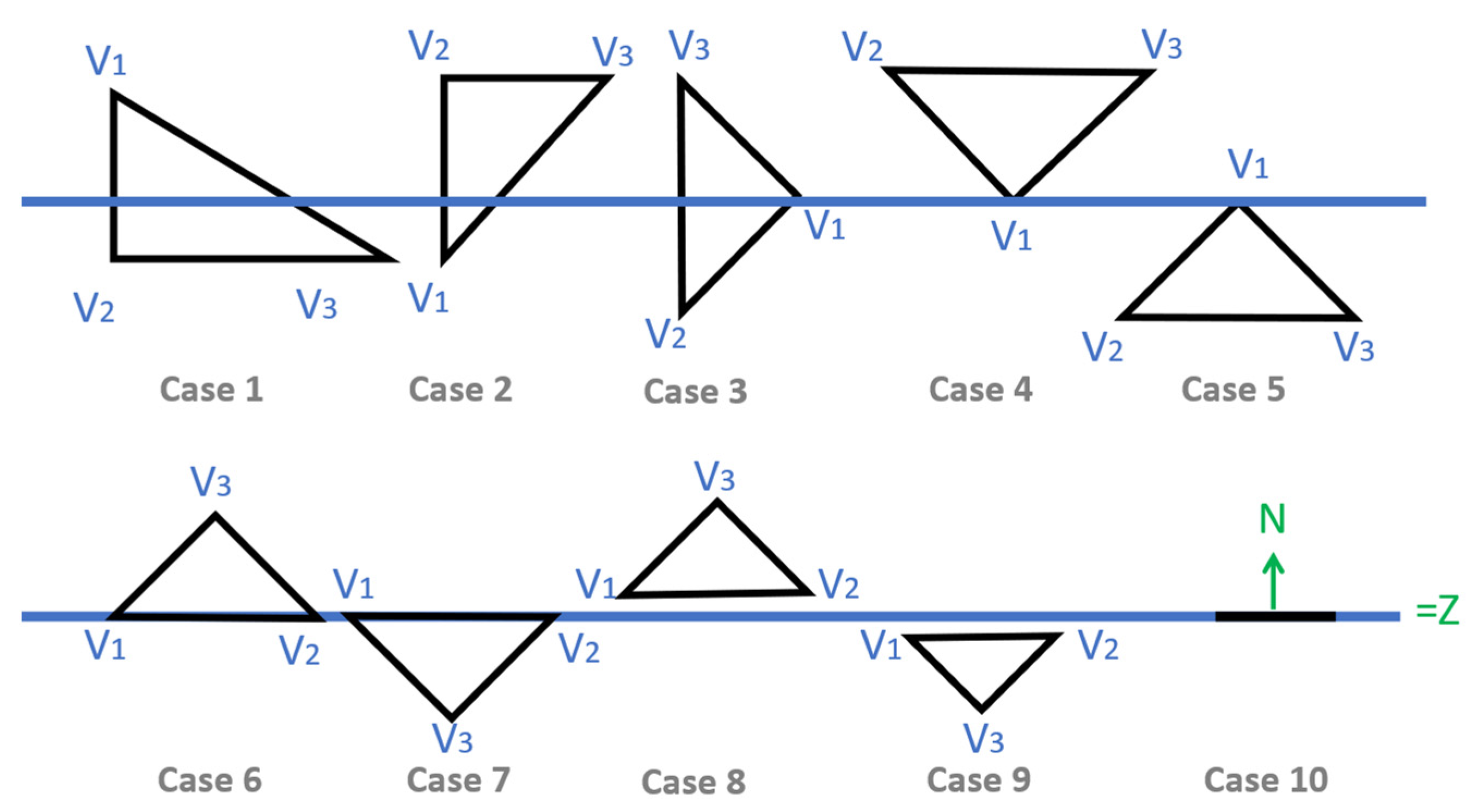
Table 2. Positional relationships of the facet and slicing plane.
CasePositional RelationshipsInterpretation
1, 2, 3 z i > z ,   z j < z ,   a n d   ( z k < z )
o r
z i < z ,   z j > z ,   a n d   ( z k > z )
such as   i , j , k = 1,3   a n d   i j k
Two intersection points P1 and P2.
P1 and P2 as the ends of a newly inserted line.
In case 3, an intersection point Pi coincides with one of the facet vertices: Vi.
4, 5 z i = z ,   z j < z ,   a n d   ( z k < z )
or
z i = z ,   z j > z ,   a n d   ( z k > z )
F contacts Sp at a single point, which is useless information for the code.
6, 7 z i = z j = z   a n d   ( z k < z )
o r
z i = z j = z   a n d   ( z k > z )
F contacts Sp with its two vertices P1 and P2.
8, 9 S p F = 0
F does not intersect Sp.
In case 9, there is free material below the triangle.
In case 8, there is free material above the triangle.
10 z i = z j = z k = z
F is parallel to the slicing plane.
Triangle V1V2V3 is created.
Table 3. Processing times.
PartsStandard Slicing (s)Adaptative Slicing (s)Time Loss (%)
A21.320321.79542.2
B47.483447.48342.0
Table 4. Constant printing parameters.
Printing ParametersValues
Filament diameter1.75 mm
Infill density10%
Raster angle0°/90°
Shell thickness1mm
Nozzle diameter0.4 mm
Fusion temperature200 °C
Bed temperature60 °C
Printing speed60 mm/s
Table 5. Inputs and results of Slicing and Printing.
PartsParametersStandard SlicingAdaptative Slicing
Design ALayer height0.2 mm0.2–0.05 mm
Number of layers414 layers439 layers
Printing time2 h 22 min 20 s2 h 29 min 53 s
Filament weight used22.11 g18.54 g
Design BLayer height0.2 mm0.2–0.05 mm
Number of layers151 layers282 layers
Printing time3 h 20 min5 h 54 min
Filament weight used78.9 g81.2 g
Table 6. Dimensional defects using RE and CMM for studied case 1 (Design A).
TolerancesRECMM
Errors of PartA1Errors of PartA2GainErrors of PartA1Errors of PartA2Gain
mm%mm%%mm%mm%%
t1 −0.720.87%−0.520.63%0.24%−0.4480.54%−0.3310.40%0.14%
t2 0.091.80%0.0450.90%0.90%−0.0971.94%−0.0911.82%0.12%
t3 −0.050.93%0.030.56%0.37%−0.0450.83%−0.0190.35%0.48%
t4 −0.090.71%−0.060.47%0.24%−0.1821.43%−0.1030.81%0.62%
t5 0.070.10%−0.060.09%0.01%−0.3950.56%−0.3230.46%0.10%
t6 −0.310.57%0.561.02%−0.45%0.2850.52%−0.0450.08%0.44%
t7 −0.060.17%−0.210.61%−0.44%0.3831.10%0.2060.59%0.51%
t8 −0.111.09%−0.1291.29%−0.20%−0.0880.88%−0.121.19%−0.31%
Table 7. Dimensional defects using RE and CMM for studied case 2 (Design B).
TolerancesRECMM
Errors of PartB1Errors of PartB2GainErrors of PartB1Errors of PartB2Gain
mm%mm%%mm%mm%%
L1 0.040.43%0.070.02%0.17%−0.0220.11%−0.070.35%−0.24%
W1 0.150.61%−0.051.45%0.02%0.13751.37%0.191.93%−0.55%
Cyl1 0.030.27%−0.042.21%−2.05%−0.0710.36%−0.401.99%−1.64%
L2 0.241.32%00.40%0.79%−0.0620.31%0.080.42%−0.11%
W2 −0.445.48%0.270.37%4.03%−0.34953.49%−0.242.36%1.13%
Cyl2 −0.322.26%0.080.09%1.51%−0.4372.19%−0.100.50%1.69%
L3 −0.10.79%−0.10.08%0.42%−0.27551.38%0.120.59%0.79%
W3 0.192.32%−0.030.48%1.42%0.3273.27%0.080.76%2.51%
Cyl3 −0.280.59%0.090.30%1.08%−0.2521.26%−0.030.17%1.09%
L −0.210.26%0.010.06%0.20%−0.1680.21%0.0430.05%0.16%
W −0.10.17%−0.150.03%0.13%−0.1030.17%0.170.28%−0.11%
H 0.420.70%−0.370.21%0.49%0.9751.63%0.5010.83%0.79%
Table 8. FFF manufacturing costs.
ItemsA1A2B1B2
Equipment purchase cost (USD)67956804
Cmh (USD)0.9200.921
Cr (USD)1.7261.4486.1616.340
Cm (USD)2.1822.2973.0695.433
Cp (USD)3.9083.7459.23011.773
Ct (USD)9.5934.1079.59312.136
PLA filament cost per Kg (USD)78.08
T (h)2400
Labor cost per hour (USD)0.363
Disclaimer/Publisher’s Note: The statements, opinions and data contained in all publications are solely those of the individual author(s) and contributor(s) and not of MDPI and/or the editor(s). MDPI and/or the editor(s) disclaim responsibility for any injury to people or property resulting from any ideas, methods, instructions or products referred to in the content.

