Article

The Effect of Niobium Addition on the Operational and Metallurgical Behavior of Fe-Cr-C Hardfacing Deposited by Shielded Metal Arc Welding

1
Departamento de Ingeniería Mecatrónica, Facultad de Ingeniería y Ciencias Básicas, Fundación Universitaria Los Libertadores, Cra 16, N. 63A-68, Bogotá 111440, DC, Colombia
2
Grupo de investigación en Corrosión, Tribología y Energía. Departamento de Ingeniería Mecánica y Mecatrónica, Facultad de Ingeniería, Universidad Nacional de Colombia, Bogotá 111321, DC, Colombia
3
Escuela de Diseño Industrial, Facultad de Artes, Universidad Nacional de Colombia, Cra 45, N. 26-85 Edificio Uriel Gutiérrez, Bogotá 111321, DC, Colombia
4
Departamento de Ingeniería Mecánica, Facultad de Ingeniería y Ciencias Básicas, Fundación Universitaria Los Libertadores, Cra 16, N. 63A-68, Bogotá 111440, DC, Colombia
5
Center for Research and Development of Welding Processes, Federal University of Uberlandia, Uberlândia 38400-901, MG, Brazil
6
Department of Engineering Science, University West, 461 86 Trollhättan, SE, Sweden
*
Author to whom correspondence should be addressed.
J. Manuf. Mater. Process. 2024, 8(1), 38; https://doi.org/10.3390/jmmp8010038
Submission received: 4 December 2023 / Revised: 5 January 2024 / Accepted: 7 January 2024 / Published: 10 February 2024
(This article belongs to the Special Issue Advances in Welding Technology)

Abstract

:
Hardfacing is commonly used in parts recovery and in obtaining surfaces with improved properties. Within this field, it is important to analyze the effect of alloying elements on the properties of the deposited layers. One of the critical parameters affecting alloying performances in SMAW is improper arc length. This article examines the effect of the addition of niobium in different quantities (0, 2, 4, 6, and 8% by weight) to the electrode coating in Fe-Cr-C shielded metal arc welding (SMAW), with short and long arc lengths, on the operational process efficiency, dilution, arc energy, microstructure, and microhardness of the deposited layers. A decrease in operational process efficiency and dilution was found with increases in niobium content. On the other hand, it was found that adding niobium leads to a refinement in chromium carbide sizes, directly affecting the hardness of the obtained deposits. There is a direct relationship between the arc energy, with both short and long arc lengths, leading to a tendency to decrease the dilution in the obtained hardfacing.

1. Introduction

Hardfacing by welding is widely applied for maintenance and repair in various industrial sectors, such as mining and sugar cane production, or simply in handling heavy machinery (agriculture, roads, and industrial processes) [1]. This technique allows for the geometric and structural recovery (mechanical properties) of large-sized parts, in addition to being used to produce parts and components of equipment subjected to abrasive wear processes [2,3]. Hardfacing applications aim to achieve an improvement in the physical and mechanical properties of a substrate, whether it is an increase in hardness [4], mechanical strength [5], surface roughness [6], toughness [7], etc.
Among the most common processes for welding hardfacing are shielded metal arc welding (SMAW) [8] and gas metal arc welding (GMAW) [9]. These welding processes are characterized by the low cost of their equipment. Despite a lower deposition capacity, the advantage of SMAW over GMAW is the possibility of controlling the deposit’s chemical composition in a more practical way. Using the SMAW process, the coating is prone to providing sufficient elements to the deposited material [10].
In the development of hardfacing, the addition of different alloying elements has been extensively studied. Chaidemenopoulos et al. [11] investigated the effects of varying alloying elements in three electrodes with chromium contents ranging from 2 to 31%, demonstrating the formation of new structures that improve the wear-resistant properties of the coatings. Meanwhile, Sairre et al. [12] studied the microstructures obtained from specimens with variations in carbon (1.4 to 5.6%) and chromium (19 to 33%) content, validating the surface and microstructures proposed by Jackson [13]. Liu et al. [14] analyzed the microstructure, growth morphology, and crystallographic characteristics of the primary carbides (Fe,Cr)C3 in hypereutectic Fe-Cr-C and found that primary carbides have irregular polygonal shapes with large holes at the center and edges. Additionally, Hornung et al. [15] studied the influence of cooling rate on the microstructure and wear behavior of hypereutectic Fe-Cr-C hard coatings and found that if the cooling rate is too fast, it has a greater influence on embrittlement and causes an increase in residual stresses, with a smaller impact on the impact resistance.
In recent years, the application scope of niobium (Nb) has increased in the metallurgical field, especially in enhancing the properties of weld deposits [16], improving cutting tool performance, and increasing anti-wear application [17,18] performance. Nb is important for obtaining hard surfaces due to its advantages in grain refinement [19] and matrix reinforcement. The potential for improving the anti-wear properties of these materials is related to their affinity for carbon and higher melting temperature compared to chromium [20]. Additionally, Nb increases the hardness (2000 HV) [11] of surfaces compared to those generated with chromium carbides (CrC) and iron carbides (Fe3C). The addition of dopant elements to such coatings affects the heat input, composition, microstructure, and hardness [21,22].
Within metallic carbides containing transition elements, niobium carbides (NbC) exhibit combinations of properties such as a high melting point (3500 °C), high hardness, low solubility in austenite [23], and high thermal and electrical conductivity; NbC has been reported as a grain growth inhibitor [24]. These properties generate interest in various applications, such as cutting tools and hard surfacing applications [17]. In a hard surface obtained from iron (Fe) with added carbon (C), chromium (Cr), and niobium (Nb), a large quantity of M7C3-type carbides are present in hyper-eutectoid, eutectoid, and hypo-eutectoid compounds [21], with hyper-eutectoid compounds being preferred. Analyzing the formation of different carbides with respect to their size and solidification temperature is important because a coarse grain size can lead to cracks during service. It has been found that surfaces with a Nb content around 3000 °C lead to the solidification of niobium carbides, while the solidification of chromium carbides begins around 1450 °C [25], giving niobium carbides the characteristics of nucleating chromium carbides [26].
The literature on hard surfaces also refers to the welding parameter behavior such as in studies that determine the effect of the distance between the electrode and the workpiece, crucial for achieving the two critical points (long arc and short arc) [20] and the impact they may have on the microstructure, deposition efficiency, and heat of the deposited weld beads [27]. The welding deposition with the longest distance between the electrode tip and plate (too-long arc) is a condition beyond which the arc extinguishes. Using the shortest distance (too-short arc) represents the condition beyond which the electrode creates a permanent bond with the plate (electrode sticking). Arc energy, as a consequence of current and arc lengths, is proportional to the amount of heat introduced into the weld. However, studies covering the influences of Nb on hardfacing properties that take into account a global relationship between the metallurgical and operational aspects are not common.
Therefore, the main objective of this work was to study the effect of Nb content in SMAW electrodes on the operational characteristics (deposition efficiency of the process, arc energy, and dilution) and metallurgical behavior (microstructural composition of deposits and their hardness) in comparison to electrodes without niobium with short and long arc lengths.

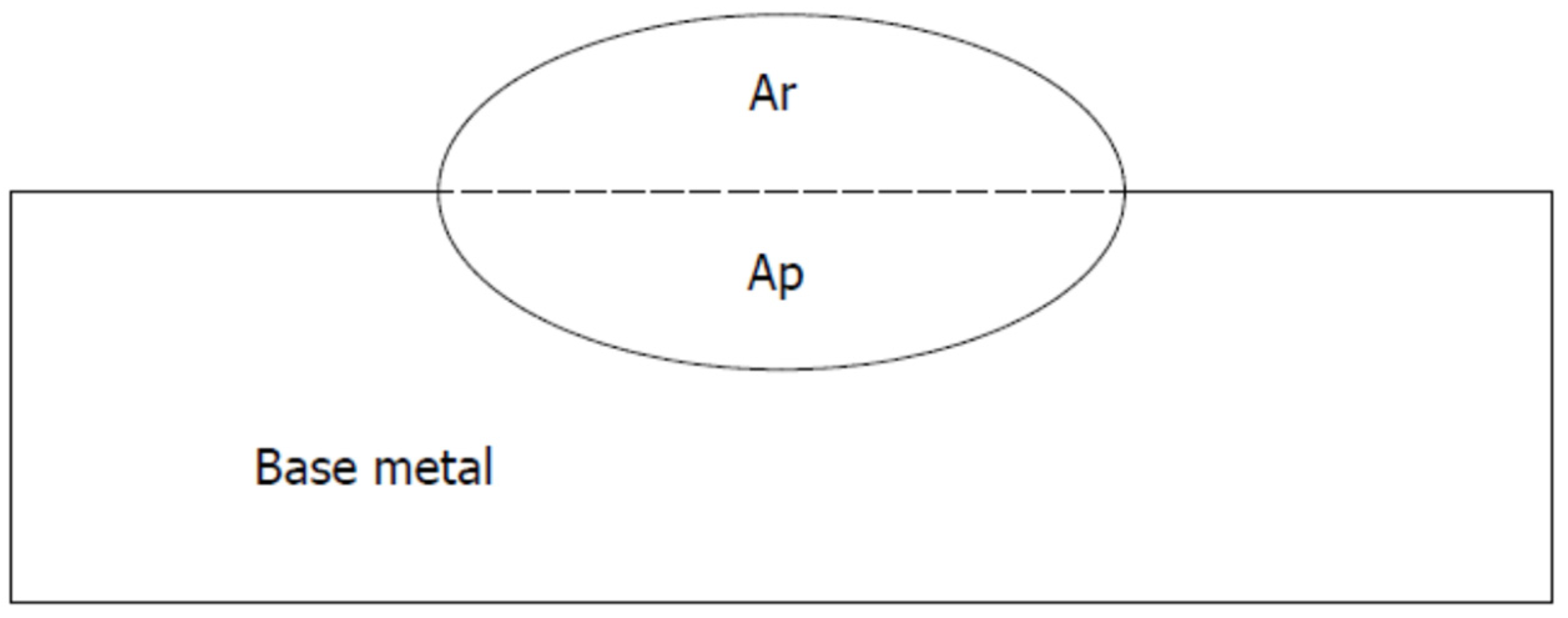
2. Materials and Methods

In this study, weld beads were deposited at the same mean current and travel speed by experimental SMAW electrodes on the surfaces of substrates (beads-on-plates) to compare their characteristics (operational and metallurgical). Two experimental blocks were carried out, one with a short arc and the other with long arcs. The Overlay 62® electrode, commercially manufactured by Indura SA, was used as the reference electrode, with a nominal deposited material chemical composition of 5% C, 3.22% Mn, 2.82% Si, and 35% Cr (by weight). Then, experimental electrode coatings were manufactured based on the reference electrode, with niobium added in approximate weights of 2%, 4%, 6%, and 8%. A roller mill equipment reference, JLN, was used to mix the coating constituents. Subsequently, an Oerlikon Model EP12 extrusion press was utilized with a working pressure of 200 ± 20 bar to obtain electrodes with the previously ground and mixed coating. These electrodes were then subjected to an electric furnace, Phoenix Model 520 NMP, and maintained at 350 °C for 1 h. Table 1 presents the chemical composition of each of the coatings, determined using a Bruker X-ray fluorescence instrument, S4 Pioneer reference. The coating, referred to as Electrode 0%Nb, is from the reference electrode.
The bead-on-plate welds were deposited over test plates (test coupons) in a flat position, forming a single layer at the center of the substrate. ASTM A36 low-carbon and non-alloyed steel bars, measuring 127 × 50.8 × 12.7 mm, were used as the substrate. These test coupons were cleaned with a wire brush to remove oxides and grease. The electrodes used were 3.2 mm in diameter and 350 mm in length, and they were operated in a pushing mode at a travel speed of 0.45 mm/s and angled at approximately 15°. One electrode was used for each deposited bead. After the depositions, the remaining material was discarded. To prevent interference from the welder, the welds were conducted using a simulator (an automatic system capable of maintaining short and long arc lengths and reasonably consistent preset travel speeds) [28]. The welding current in DCEP (direct current electrode positive) was set at 120 A for each test. For that, an electronic power source set to work in constant current mode was employed.
The test plates and electrodes were weighed before and after the welding to determine the fusion and deposition rates, i.e., the mass loss from the electrodes and the weight gained by each substrate were determined. Both the substrate and electrodes were weighed using a Radwag Analytical Balance, AS reference, with a resolution of 0.001 g. Subsequently, samples were cut from each of the substrates. Cross-sectional samples were prepared from each test plate for macrographic analysis. The microhardness, microstructure, and metallurgical phases of these cross-sections were analyzed using scanning electron microscopy (SEM) and X-ray diffraction (XRD). In this context, the metallurgical phases refer to the projections obtained from the Fe-C-Cr ternary phase diagram that can be present with these alloying element contents. Current and voltage data were recorded for each bead deposition, at a rate of 10 kHz, with a resolution of 12 bits per 6 s. A specialized computational program processed the data to characterize the metal transfer phenomenon (total and short-circuiting frequencies with metal transfer, and total and short-circuiting average time).
Arc energy and heat input are closely related and are two important aspects that affect the quality and integrity of overlay welding. Arc energy refers to the thermal energy generated by the electric arc between the electrode and the base material during the welding process. This energy is essential for melting the electrode and the base material, creating a strong bond. The arc temperature is extremely high and can reach thousands of degrees Celsius, allowing material fusion. Heat input, on the other hand, refers to the total amount of heat introduced into the workpiece during the welding process. This heat input comes from both the electric arc and the filler material (electrode) being deposited at the joint. However, the heat input is very difficult to estimate with precision, since it depends on several factors (arc length, substrate dimensions, etc.). Arc energy, in turn, can be calculated using Equation (1) [29], where instantaneous power is typically used.
E n = 1 n i = 1 n U i × I i V
where:
  • En: average arc energy;
  • U(i): instantaneous arc voltage;
  • I(i): instantaneous welding current;
  • V: welding travel speed.
The deposit efficiency was calculated using Equation (2) [28]. The plate and the electrode (including the coating) were weighed before and after the welding bead was deposited, removing the slag produced on the surface of the plate. The information was tabulated to calculate the deposited mass on the plate and the lost mass in the electrode based on the difference in mass. This provided the process efficiency, which was calculated using Equation (2). It is important to mention that this method to calculate deposition efficiency (%) for SMAW electrodes is usually referred to as the actual efficiency. As seen in most commercial SMAW electrode datasheets, this measurement method accounts only for the electrode’s metallic core (rod). Naturally, the traditional method used by SMAW electrode manufacturers presents higher values (sometimes higher than 100% for the high deposition efficiency electrodes) than the actual method, which have more commercial appeal, but are less realistic.
ηd = (Δsdm/Δeml) × 100
where:
  • ηd = actual deposition efficiency;
  • Δsdm = deposited mass on the substrate;
  • Δeml = electrode mass loss.
Cross-sections of the welded sheet were cut off to obtain samples, which were characterized using XRD and SEM. For microstructural analysis, the samples were polished, etched with aqua regia, and observed using an F.E.I. Quanta 20 SEM microscope. XRD analyses were conducted on a PANalytical Xpert Pro instrument using the following conditions: θ–2θ ranging from 10° to 120°, monochromatic Cu Kα radiation (λ = 1.5409 Å), 45 kV, 40 mA, and a step size of 0.02°. Five microhardness values were recorded from each sample using a Leco M-400-G2 microdurometer, with an approach speed of 2000 nm/min, a maximum load of 500 g, and a dwell time of 10 s. Mean values with standard deviations were calculated for each sample.
Concerning dilution, this measurable quantity is defined as the ratio between the cross-sectional area of the weld metal below the original surface (Ar) and the total area of the weld measured in the cross-section of the weld metal (Ar + Ap) [30,31]. Equation (3) was used to calculate the dilution percentage:
D i l u t i o n = A p A p + A r × 100
The areas Ap and Ar for the dilution calculation were based on images like the one observed in Figure 1, which were taken from the coatings deposited with one layer.

3. Results

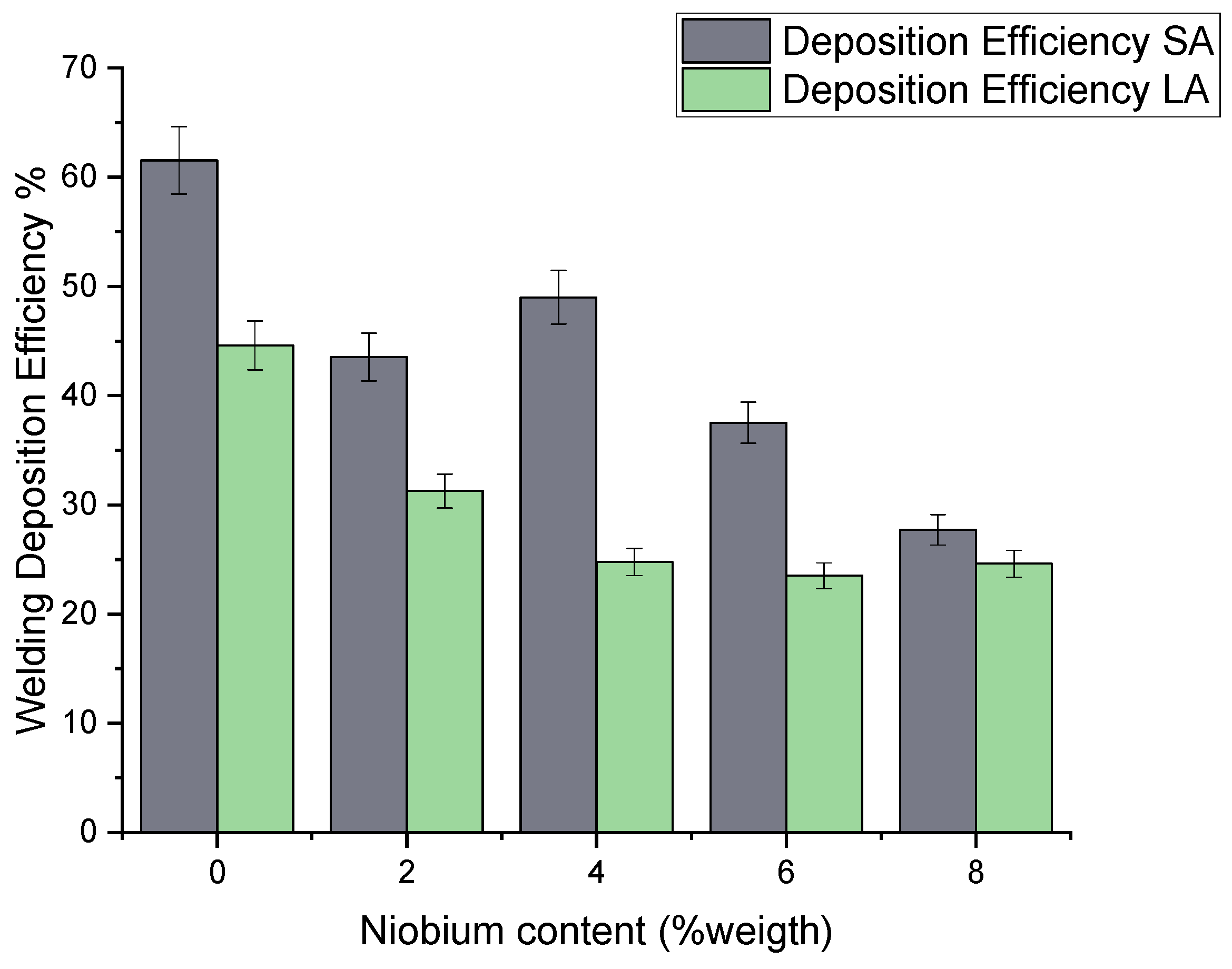
3.1. Deposition Efficiency of the Electrodes

The deposition efficiency performance for the electrode while varying the Nb content and arc length is presented in Figure 2. This figure shows that the coatings obtained with niobium-free electrodes had the highest performance (ηd around 60% in short-arc). A higher content reduced the deposition efficiency (spattering and slags losses from 55% to 25%). The trends are more evident for the short arcs, where the metal transfer is more regular. In Figure 2, one can also observe the trend that, as expected, the deposition efficiency with long arcs (LA) is smaller and connected to less regular transfer (i.e., more spattering), but also that long arcs augment the droplet formation time at the electrode tip [24], favoring more fume formation. Regardless, the trends are more evident for long arcs (LA). With short arcs (SA), the only outlying result was observed at 4% Nb. This may be due to the small sample size (only three electrodes) of each composition, considering the variance (denoted by error bars in the chart).
The arc energy employed in all the bead depositions, obtained from Equation (1), is presented in Figure 3 and Table 2. It must be noted that the set current and travel speed were the same. However, the arc lengths were purposely changed, leading to higher voltages in the long-arc experiments. This justifies using a higher arc energy when longer arc lengths (LA) are employed. Figure 3 shows no influence of Nb content on the arc energy where the measuring uncertainties (indicated by the standard deviations and error bars) are considered.
The relationship between the Nb content and dilution, calculated using Equation (3), is presented in Figure 4. This figure shows a decrease in the dilution percentage based on the niobium content, regardless of the arc length. This can be explained by the fact that niobium is an alloying element that facilitates carbide formation in the deposited beads, which could help restrict the fusion of the base metal during the welding process [17,19,30]. This means that the base metal mixes less with the filler metal, reducing dilution. As a result, the hardfacing experiences fewer changes in its nominal chemical composition, which could be beneficial for maintaining the desired properties in the weld [31,32].

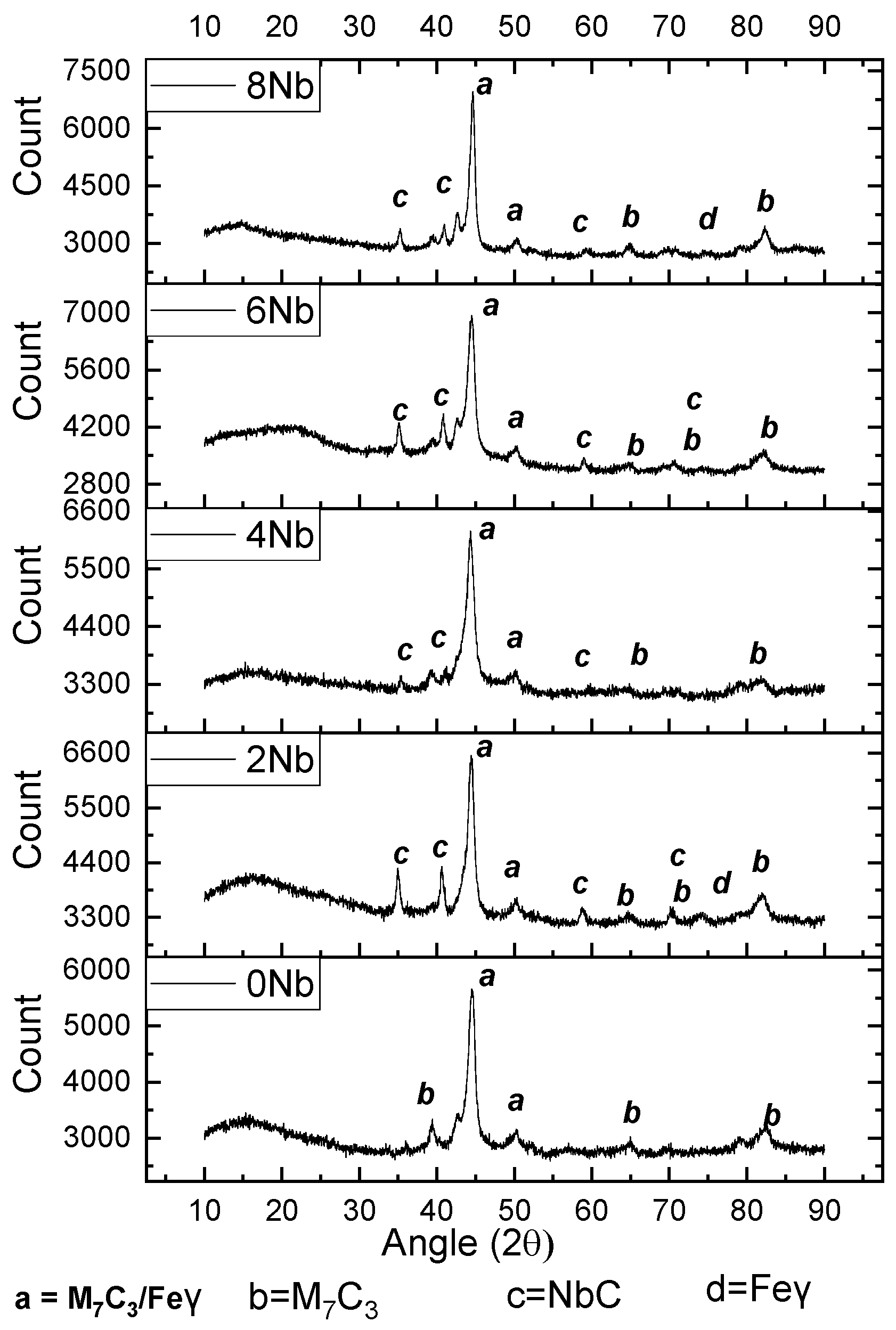
3.2. X-ray Diffraction

Figure 5 presents the result of the XRD analysis of the studied coatings. Here, the formation of the main structures typical of deposits with this type of SMAW electrode (Fe-Cr-C and Fe-Cr-C-Nb) is observed: niobium carbides (NbC), chromium carbides [33], and iron carbides of M7C3 type in a matrix of ferrite, martensite, or austenite (Fe γ) [24,34,35]. Liu et al. [26] believe that the precipitation of niobium carbides occurs at a higher temperature than the formation of chromium carbides, 1350 °C, which is 50 °C above the temperature at which the eutectic reaction initiates and the formation of chromium carbides. The eutectic reaction (liquid–Eutectic M7C3 carbide + eutectic austenite) occurs at 1300 °C. The initial formation of niobium carbides implies that they are present in chromium carbide as grain formers. They are crucial in refining the grain size present in hard surfaces obtained with niobium additions. Only the diffractogram for the short arc is shown, as no difference was observed in that obtained for the long arcs.

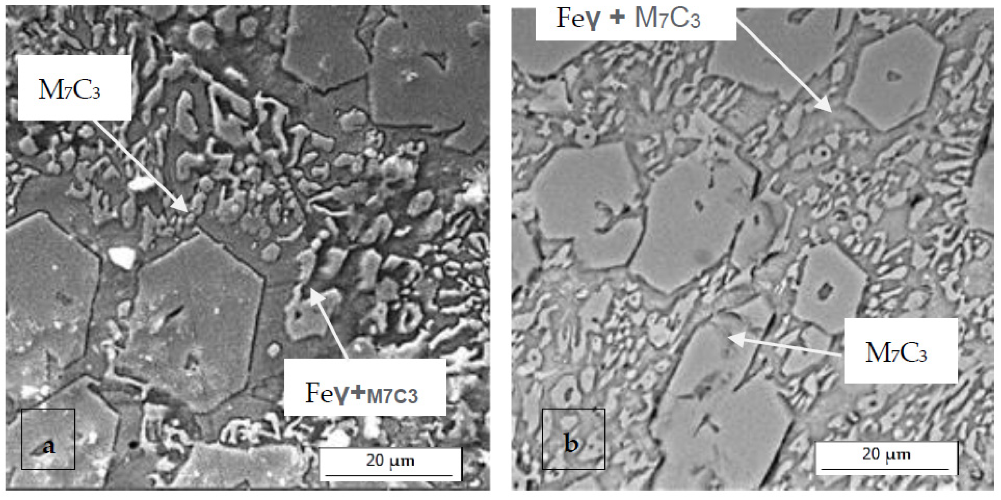
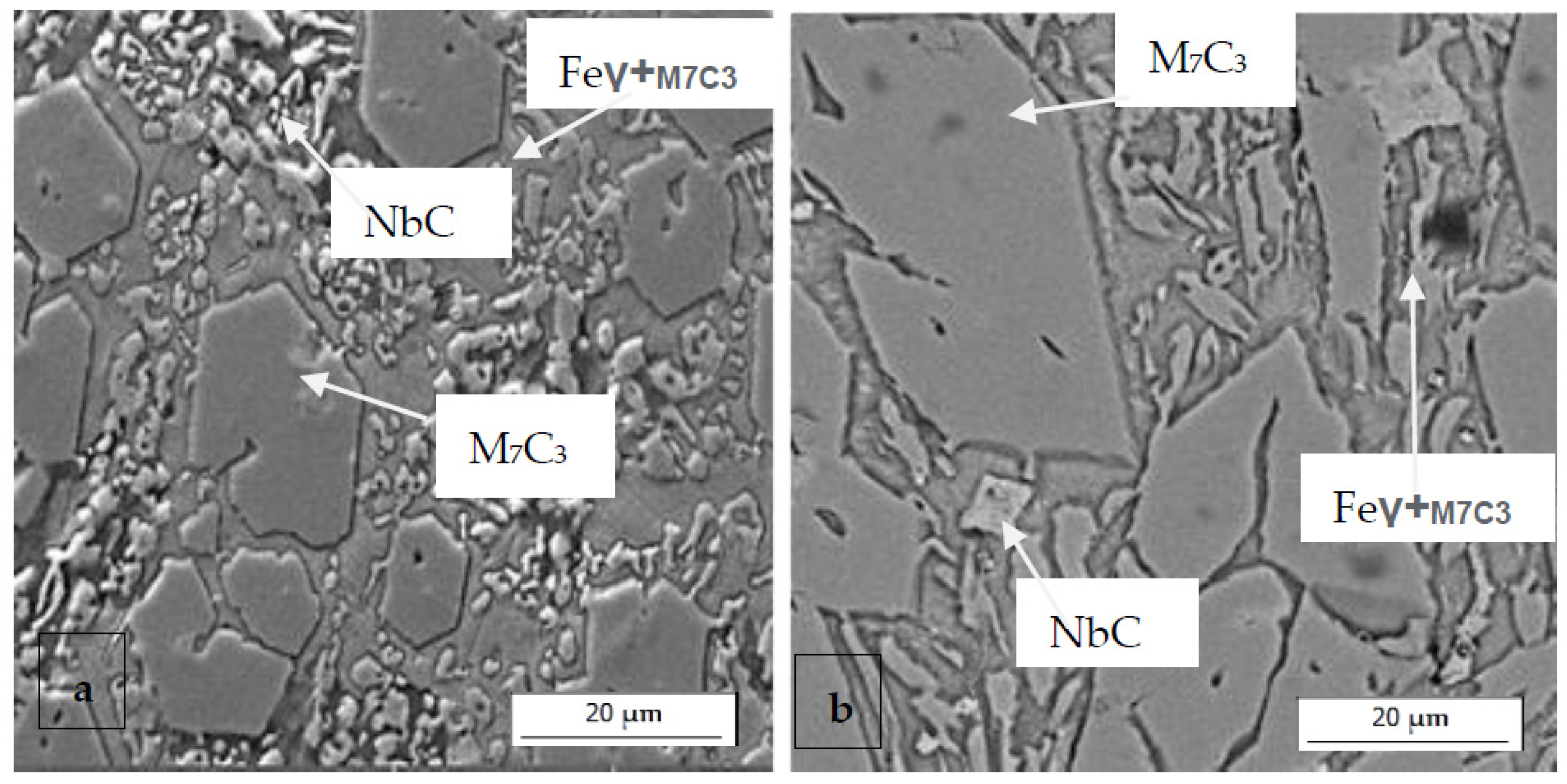
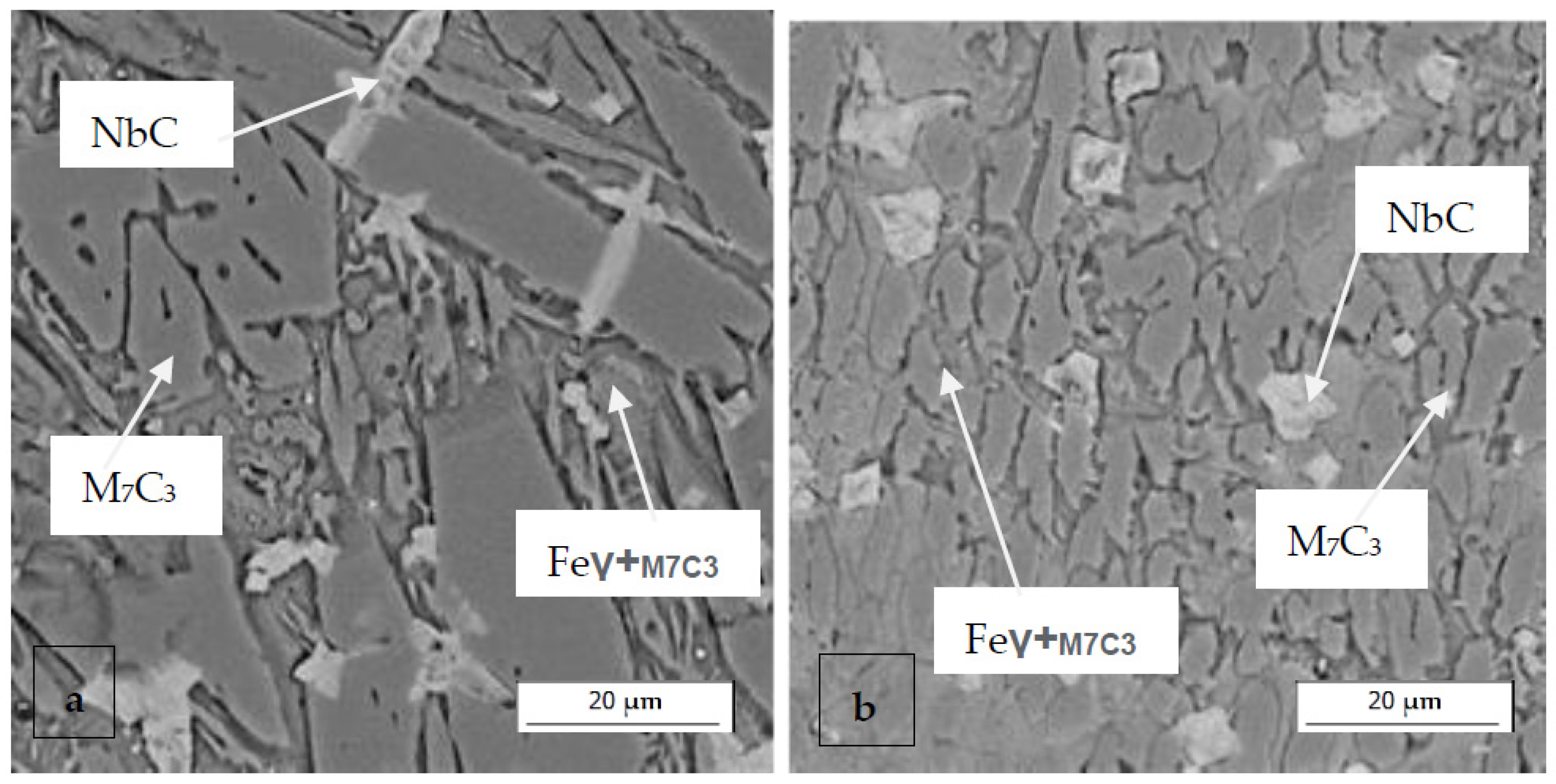
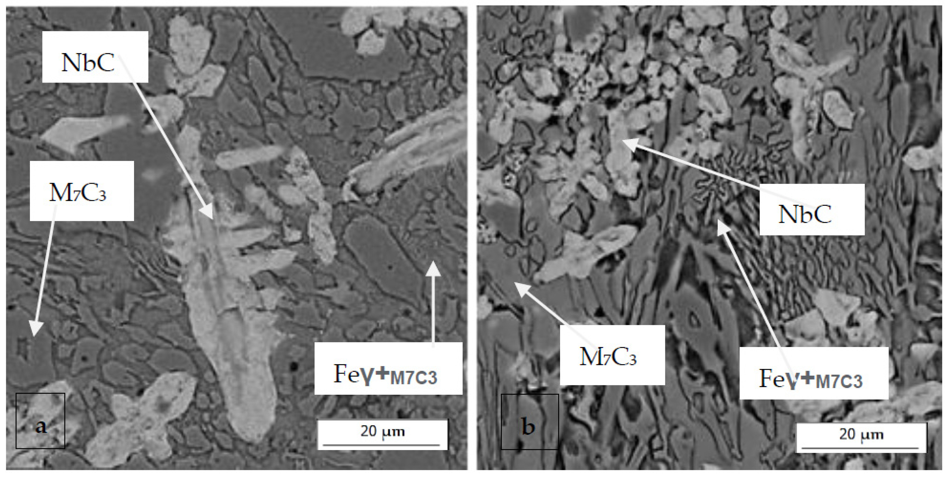
3.3. Scanning Electron Microscopy
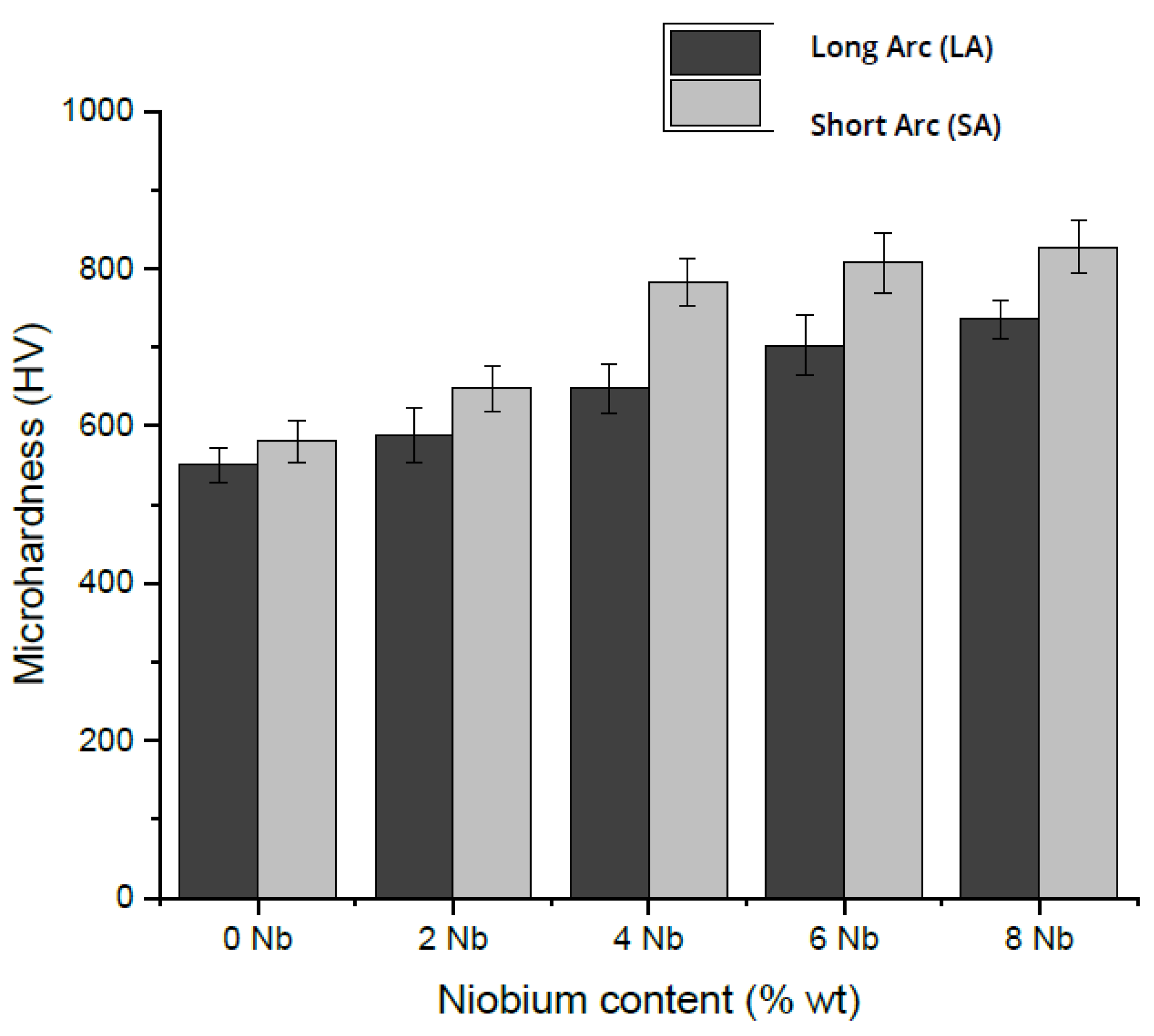
Images were taken using scanning electron microscopy (SEM) with a magnification of 3000. Figure 6 shows SEM images of the cross-sections of coatings without Nb, deposited with short and long arcs, where the formation of chromium carbides with their characteristic hexagonal morphology is observed [14,36]. Images of cross-sections from hardfacing beads with 0, 2, 4, 6, and 8% Nb are shown in Figure 6, Figure 7, Figure 8, Figure 9 and Figure 10, respectively. With the increase in Nb, the size of the chromium carbides tends to decrease under both short-arc and long-arc conditions. Additionally, niobium carbides increase in size and quantity, which is consistent with what has been reported by various authors regarding the characteristic microstructure present in this type of coating [15,26,30,37,38,39,40,41]. Niobium carbides act as chromium carbide formers because the latter requires lower temperatures for its formation, resulting in increases in quantity and grain size as the niobium content in the electrode used for coating deposition increases [18]. Because of the lower dilution, when the niobium content is increased, the quantity of niobium carbides can be observed, mainly due to the higher amount of this element available for forming carbides. In Figure 7, Figure 8, Figure 9 and Figure 10, the white areas (niobium carbides) can be observed to grow in number and size depending on the amount of niobium incorporated into the electrode coating.

3.4. Microhardness

Figure 11 presents the microhardness values as a function of niobium content under long-arc (LA) and short-arc (SA) conditions. The values for the hardfacing cross-sections obtained with varying niobium content under both short- and long-arc conditions are shown.
Based on the XRD and SEM results obtained, coatings with 0, 2, and 4% niobium have similar microhardness values, mainly because variations in the microstructure are related to the size of the chromium and niobium carbides, without affecting the existing structure. Meanwhile, for the coating with 6 and 8% niobium, changes in the morphology and distribution of the carbides were observed, shifting from the defined hexagonal structures for M7C3-type chromium carbides to a eutectic matrix with austenite content and larger formations of niobium carbides (NbC) than those obtained with other niobium contents.

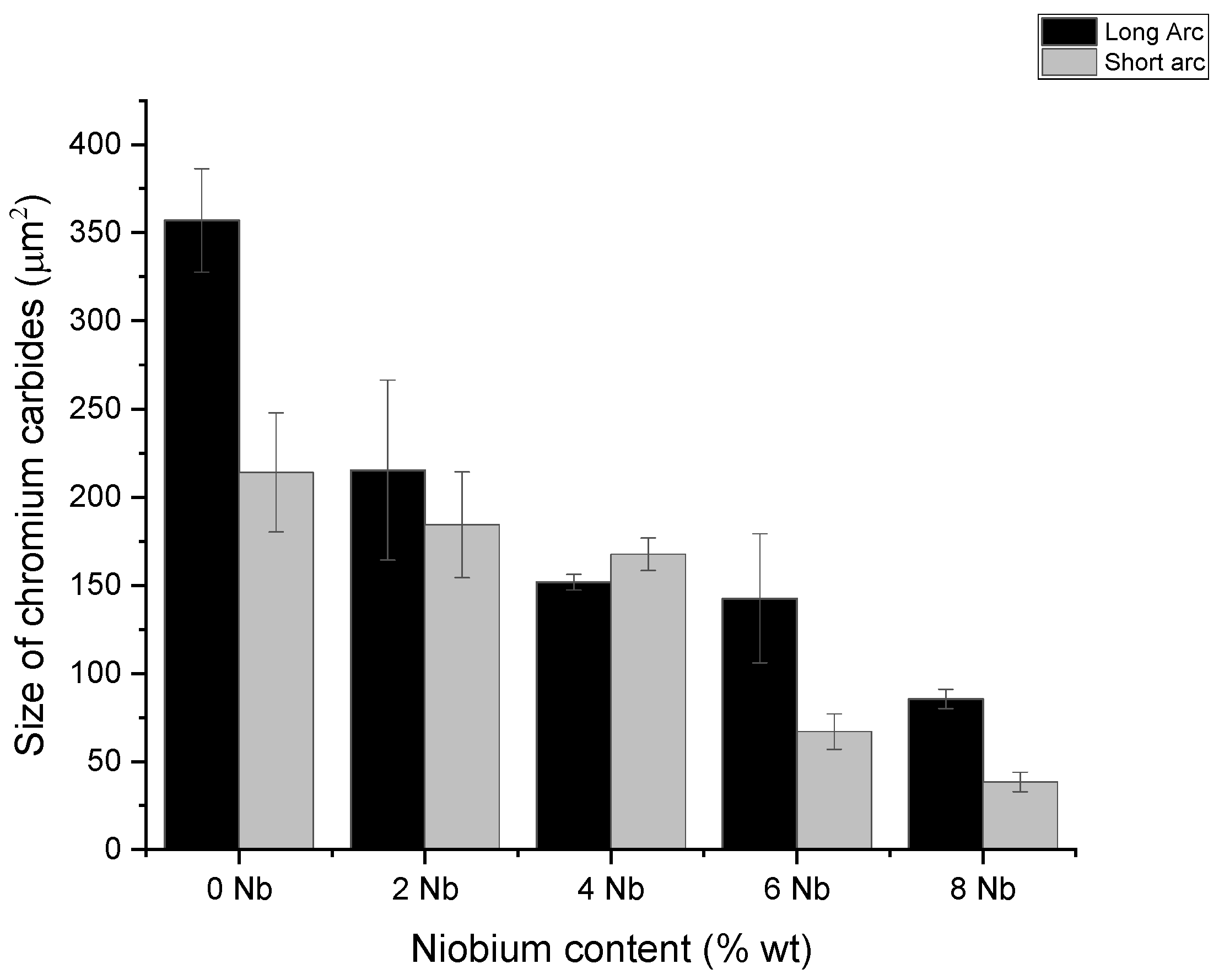
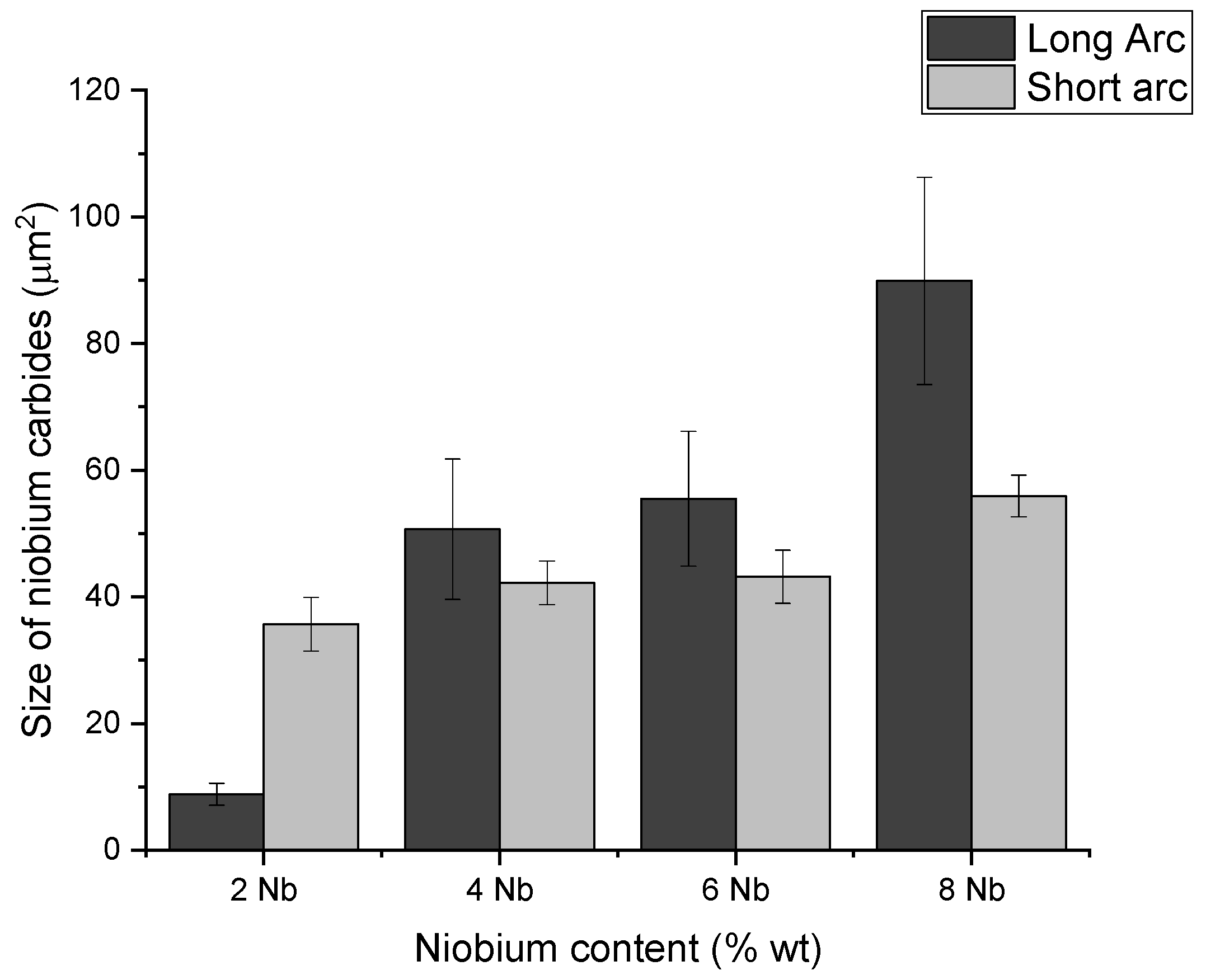
3.5. Measurement of Carbide Sizes

For the samples obtained with different niobium content, measurements of the sizes (areas) of chromium and niobium carbides were conducted. These measurements were carried out with the assistance of the ImageJ® program, which allows for image measurement using a pixel-based approach, converting these pixels into the specified scale. Figure 12 shows the results obtained by measuring the size of the chromium carbides. It can be observed that there is a decrease in size as a function of niobium content, which is in accordance with findings reported by [19,27,42]. These studies found that the addition of niobium to coatings with added chromium leads to a decrease in the size of the chromium carbides with increasing niobium content. This aligns with what is observed in Figure 13, where the size of the niobium carbides increases in accordance with the niobium content, except in the case of samples with 6% Nb and higher, where the carbide size stabilizes, and a larger number of carbides can be observed, albeit with similar sizes, as seen in Figure 6, Figure 7, Figure 8, Figure 9 and Figure 10.
For the coating (one layer) generated with 120 A with additions above two percent niobium content (2% Nb), the obtained peaks are shown in the diffractogram (Figure 5). The additional formation of niobium carbides (NbC) [111] is observed, in comparison to the case of the zero-niobium coating. This formation is due to the higher solidification temperature found in these carbides [26], allowing these carbides to form and solidify at higher temperatures than the chromium carbides. The refinement in size [43,44] of the niobium-added hard coatings was observed; adding niobium decreases the average size of the carbides [24,41]. The initial formation of niobium carbides implies that they are present in the chromium carbide as grain formers and suggests that they are the crucial factor in refining the grain size present in the coatings obtained with niobium addition.

4. Conclusions

The objective of this work was to analyze the influence of niobium on the arc behavior produced under two conditions (short and long arcs), and based on these conditions, evaluate the obtained coatings. From the results, it was concluded that:
  • The increased content of Nb in the electrode coatings led to:
    A decrease in deposition efficiency (reducing the operational capacity of the electrodes).
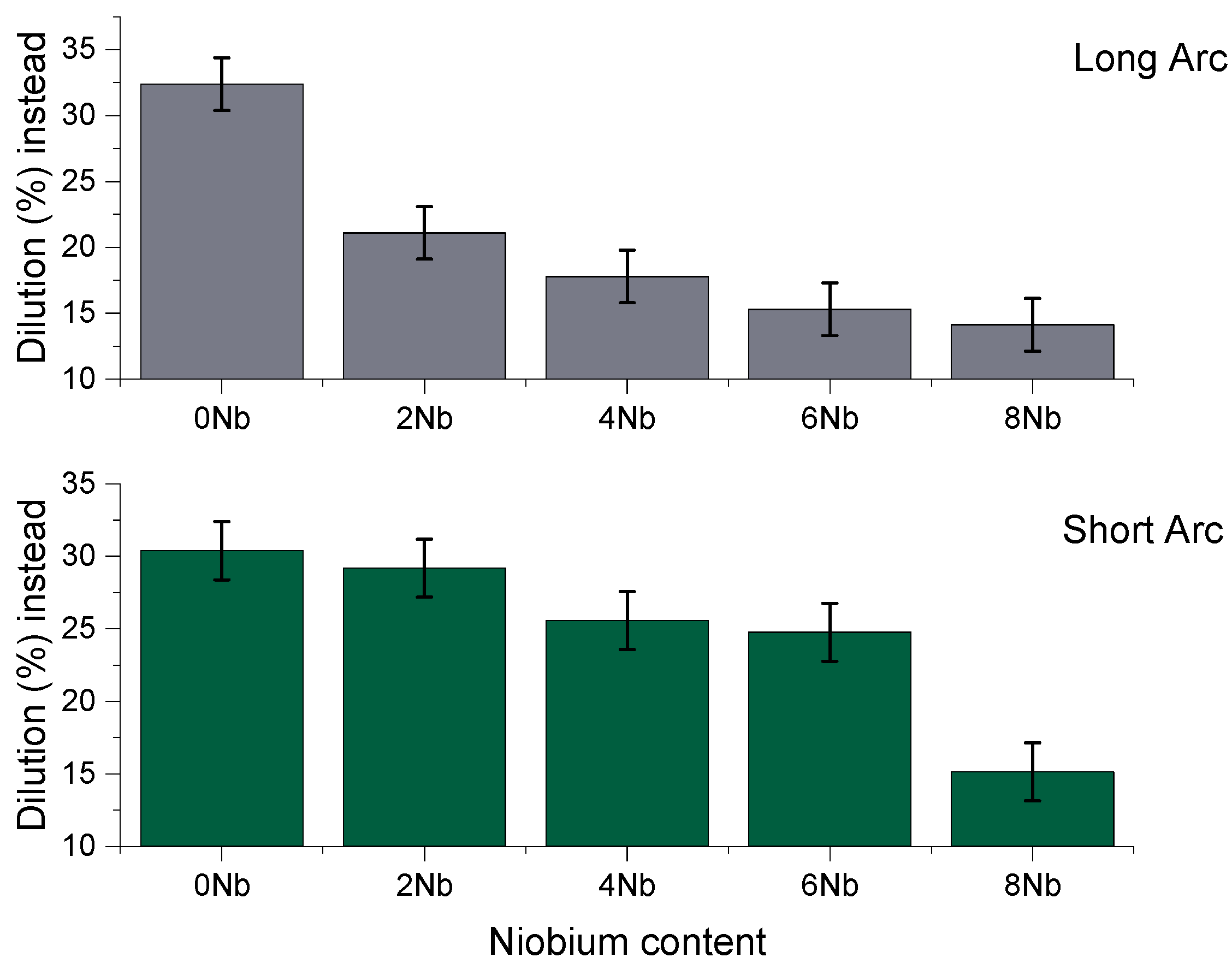
    A deposit with lower dilution (which is positive since the substrate is not alloyed).
  • Assisted by the lower dilution, the deposits with higher Nb content presented higher hardness, which is beneficial in wear-resistant applications.
  • In addition, the Cr carbides became finer with the addition of Nb (coarser carbides).
  • Concerning the effect of arc length, higher deposition efficiency is reached in short arcs.
Note: The researcher will continue to address the comparative performance of electrodes with and without Nb, yet with two or three coating layers. This approach will enable a more in-depth analysis to determine the most suitable niobium content, if this is the case.

Author Contributions

Conceptualization, J.P., O.P. and J.O.; methodology, investigation, and writing, J.P., O.P. and A.S.; supervision, J.G.; funding acquisition, O.P. All authors have read and agreed to the published version of the manuscript.

Funding

This research was funded by Ministry of Science and Technology, Colombia, and Colciencias through call 6172 and through the national call for support for the development of postgraduate theses or final specialization projects in the health area, from the Universidad Nacional of Colombia, 2017–2018.

Data Availability Statement

Data are contained within the article.

Conflicts of Interest

The authors declare that they have no known competing financial interests or personal relationships that could have influenced the work reported in this paper.

References

  1. Buchanan, V.; Shipway, P.; McCartney, D. Microstructure and abrasive wear behaviour of shielded metal arc welding hardfacings used in the sugarcane industry. Wear 2007, 263, 99–110. [Google Scholar] [CrossRef]
  2. Srikarun, B.; Oo, H.Z.; Petchsang, S.; Muangjunburee, P. The effects of dilution and choice of added powder on hardfacing deposited by submerged arc welding. Wear 2019, 424–425, 246–254. [Google Scholar] [CrossRef]
  3. Liu, D.; Liu, R.; Wei, Y.; Ma, Y.; Zhu, K. Microstructure and wear properties of Fe–15Cr–2.5Ti–2C–xBwt.% hardfacing alloys. Appl. Surf. Sci. 2013, 271, 253–259. [Google Scholar] [CrossRef]
  4. Chatterjee, S.; Pal, T. Weld procedural effect on the performance of iron based hardfacing deposits on cast iron substrate. J. Am. Acad. Dermatol. 2006, 173, 61–69. [Google Scholar] [CrossRef]
  5. Badisch, E.; Kirchgaßner, M.; Polak, R.; Franek, F. The comparison of wear properties of different Fe-based hardfacing alloys in four kinds of testing methods. Tribotest 2008, 14, 225–233. [Google Scholar] [CrossRef]
  6. Findik, F. Latest progress on tribological properties of industrial materials. Mater. Des. 2014, 57, 218–244. [Google Scholar] [CrossRef]
  7. Ripoll, M.R.; Ojala, N.; Katsich, C.; Totolin, V.; Tomastik, C.; Hradil, K. The role of niobium in improving toughness and corrosion resistance of high speed steel laser hardfacings. Mater. Des. 2016, 99, 509–520. [Google Scholar] [CrossRef]
  8. Buchanan, V.; McCartney, D.; Shipway, P. A comparison of the abrasive wear behaviour of iron-chromium based hardfaced coatings deposited by SMAW and electric arc spraying. Wear 2008, 264, 542–549. [Google Scholar] [CrossRef]
  9. Günther, K.; Bergmann, J.P.; Suchodoll, D. Hot wire-assisted gas metal arc welding of hypereutectic FeCrC hardfacing alloys: Microstructure and wear properties. Surf. Coat. Technol. 2018, 334, 420–428. [Google Scholar] [CrossRef]
  10. Pérez-Cepeda, J.A.; de Colombia, U.N.; Olaya-Flórez, J.J. Influence of the type of electrode on the microstructure and coefficient of friction obtained by sliding test to hard coatings deposited by welding SMAW. Ing. Y Desarro. 2018, 36, 327–342. [Google Scholar] [CrossRef]
  11. Chaidemenopoulos, N.; Psyllaki, P.; Pavlidou, E.; Vourlias, G. Aspects on carbides transformations of Fe-based hardfacing deposits. Surf. Coatings Technol. 2019, 357, 651–661. [Google Scholar] [CrossRef]
  12. de Sairre, P.; Scotti, A.; Biasoli, J. Interpretacion de la microestructira de recargues duros depositados por soldadura utilizando la superficie de Liquidus de Diagramas Fe-Cr-C. Rev. De Sold. CENIN 1995, 25, 199–207. [Google Scholar]
  13. Jackson, R. The Austenite Liquidus Surface and Constitutional Diagram for the Fe-Cr-C Metastable System. Iron Steel Inst. 1970, 208, 163–167. [Google Scholar]
  14. Liu, S.; Zhou, Y.; Xing, X.; Wang, J.; Yang, Y.; Yang, Q. Agglomeration model of (Fe,Cr)7C3 carbide in hypereutectic Fe-Cr-C alloy. Mater. Lett. 2016, 183, 272–276. [Google Scholar] [CrossRef]
  15. Hornung, J.; Zikin, A.; Pichelbauer, K.; Kalin, M.; Kirchgaßner, M. Influence of cooling speed on the microstructure and wear behaviour of hypereutectic Fe–Cr–C hardfacings. Mater. Sci. Eng. A 2013, 576, 243–251. [Google Scholar] [CrossRef]
  16. Zhou, X.; Chen, Y.; Huang, Y.; Mao, Y.; Yu, Y. Effects of niobium addition on the microstructure and mechanical properties of laser-welded joints of NiTiNb and Ti6Al4V alloys. J. Alloys Compd. 2018, 735, 2616–2624. [Google Scholar] [CrossRef]
  17. Woydt, M.; Huang, S.; Vleugels, J.; Mohrbacher, H.; Cannizza, E. Potentials of niobium carbide (NbC) as cutting tools and for wear protection. Int. J. Refract. Met. Hard Mater. 2018, 72, 380–387. [Google Scholar] [CrossRef]
  18. Zhao, C.; Zhou, Y.; Xing, X.; Liu, S.; Ren, X.; Yang, Q. Investigation on the relationship between NbC and wear-resistance of Fe matrix composite coatings with different C contents. Appl. Surf. Sci. 2018, 439, 468–474. [Google Scholar] [CrossRef]
  19. Zhi, X.H.; Wang, J.X. Effect of niobium on primary carbides of hypereutectic high chromium cast iron. Ironmak. Steelmak. 2014, 41, 394–399. [Google Scholar] [CrossRef]
  20. Singla, Y.K.; Arora, N.; Dwivedi, D.K.; Rohilla, V. Influence of niobium on the microstructure and wear resistance of iron-based hardfacings produced by pre-placement technique—A novel approach. Int. J. Adv. Manuf. Technol. 2017, 93, 2667–2674. [Google Scholar] [CrossRef]
  21. Cruz-Crespo, A.; Fernández-Fuentes, R.; Ferraressi, A.V.; Gonçalves, R.A.; Scotti, A. Microstructure and Abrasion Resistance of Fe-Cr-C and Fe-Cr-C-Nb Hardfacing Alloys Deposited by S-FCAW and Cold Solid Wires. Soldag. Inspeção 2016, 21, 342–353. [Google Scholar] [CrossRef]
  22. Yang, K.; Gao, Y.; Bao, Y.; Jiang, Y. Microstructure and wear resistance of Fe-Cr13-C-Nb hardfacing alloy with Ti addition. Wear 2017, 376–377, 1091–1096. [Google Scholar] [CrossRef]
  23. Cuppari, M.G.D.V.; Santos, S.F. Physical Properties of the NbC Carbide. Metals 2016, 6, 250. [Google Scholar] [CrossRef]
  24. Correa, E.; Alcântara, N.; Valeriano, L.; Barbedo, N.; Chaves, R. The effect of microstructure on abrasive wear of a Fe–Cr–C–Nb hardfacing alloy deposited by the open arc welding process. Surf. Coatings Technol. 2015, 276, 479–484. [Google Scholar] [CrossRef]
  25. Berns, H.; Fischer, A. Microstructure of Fe-Cr-C hardfacing alloys with additions of Nb, Ti and, B. Mater. Charact. 1997, 39, 499–527. [Google Scholar] [CrossRef]
  26. Liu, S.; Wang, Z.; Shi, Z.; Zhou, Y.; Yang, Q. Experiments and calculations on refining mechanism of NbC on primary M7C3 carbide in hypereutectic Fe-Cr-C alloy. J. Alloys Compd. 2017, 713, 108–118. [Google Scholar] [CrossRef]
  27. Pourasiabi, H.; Gates, J. Effects of niobium macro-additions to high chromium white cast iron on microstructure, hardness and abrasive wear behaviour. Mater. Des. 2021, 212, 110261. [Google Scholar] [CrossRef]
  28. Crespo, A.C.; Scotti, A.; Pérez, M.R. Operational behavior assesment of coated tubular electrodes for SMAW hardfacing. J. Mater. Process. Technol. 2008, 199, 265–273. [Google Scholar] [CrossRef]
  29. Scotti, A.; Batista, M.A.; Eshagh, M. Inaccuracy in arc power calculation through a product of voltage and current averages. J. Braz. Soc. Mech. Sci. Eng. 2022, 44, 11. [Google Scholar] [CrossRef]
  30. Zhi, X.; Xing, J.; Fu, H.; Xiao, B. Effect of niobium on the as-cast microstructure of hypereutectic high chromium cast iron. Mater. Lett. 2008, 62, 857–860. [Google Scholar] [CrossRef]
  31. Aishwarya; Jain, A.; Khanna, P. Mathematical modeling to predict the weld dilution in FCA welding of stainless steel 301 plates. Mater. Today Proc. 2022, 56, 755–759. [Google Scholar] [CrossRef]
  32. Lemke, J.; Rovatti, L.; Colombo, M.; Vedani, M. Interrelation between macroscopic, microscopic and chemical dilution in hardfacing alloys. Mater. Des. 2016, 91, 368–377. [Google Scholar] [CrossRef]
  33. de Sousa, J.M.S.; Lobato, M.Q.; Garcia, D.N.; Machado, P.C. Abrasion resistance of Fe–Cr–C coating deposited by FCAW welding process. Wear 2021, 476, 203688. [Google Scholar] [CrossRef]
  34. Jeng, S.-L.; Chang, Y.-H. The influence of Nb and Mo on the microstructure and mechanical properties of Ni–Cr–Fe GTAW welds. Mater. Sci. Eng. A 2012, 555, 1–12. [Google Scholar] [CrossRef]
  35. Chang, C.-M.; Lin, C.-M.; Hsieh, C.-C.; Chen, J.-H.; Wu, W. Micro-structural characteristics of Fe–40wt%Cr–xC hardfacing alloys with [1.0–4.0wt%] carbon content. J. Alloys Compd. 2009, 487, 83–89. [Google Scholar] [CrossRef]
  36. Jankauskas, V.; Antonov, M.; Varnauskas, V.; Skirkus, R.; Goljandin, D. Effect of WC grain size and content on low stress abrasive wear of manual arc welded hardfacings with low-carbon or stainless steel matrix. Wear 2015, 328–329, 378–390. [Google Scholar] [CrossRef]
  37. Wang, J.; Liu, T.; Zhou, Y.; Xing, X.; Liu, S.; Yang, Y.; Yang, Q. Effect of nitrogen alloying on the microstructure and abrasive impact wear resistance of Fe-Cr-C-Ti-Nb hardfacing alloy. Surf. Coatings Technol. 2016, 309, 1072–1080. [Google Scholar] [CrossRef]
  38. Yang, J.; Huang, J.; Fan, D.; Chen, S. Microstructure and wear properties of Fe–6wt.%Cr–0.55wt.%C–Xwt.%Nb laser cladding coating and the mechanism analysis. Mater. Des. 2015, 88, 1031–1041. [Google Scholar] [CrossRef]
  39. Zhang, L.; Sun, D.; Yu, H. Effect of niobium on the microstructure and wear resistance of iron-based alloy coating produced by plasma cladding. Mater. Sci. Eng. A 2008, 490, 57–61. [Google Scholar] [CrossRef]
  40. Liu, H.-Y.; Song, Z.-L.; Cao, Q.; Chen, S.-P.; Meng, Q.-S. Microstructure and properties of Fe-Cr-C hardfacing alloys reinforced with TiC-NbC. J. Iron Steel Res. Int. 2016, 23, 276–280. [Google Scholar] [CrossRef]
  41. Osorio, A.; Souza, D.; dos Passos, T.; Dalpiaz, L.; Aires, T. Effect of niobium addition on the flux of submerged arc welding of low carbon steels. J. Am. Acad. Dermatol. 2019, 266, 46–51. [Google Scholar] [CrossRef]
  42. Sandhu, G.S.; Singh, R.; Singh, I.; Khan, F. Effect of Chromium Content Variation on Wear Resistance of Rotavator Blades. Int. Res. J. Eng. Technol. 2017, 4, 1038–1043. Available online: https://www.irjet.net/archives/V4/i5/IRJET-V4I5202.pdf (accessed on 5 June 2021).
  43. de Sousa, J.M.S.; Gil, G.S.; Barbosa, M.d.S.; Garcia, D.N.; Lobato, M.Q.; Machado, P.C. Tribological performance under abrasive wear of Fe-Cr-C+Nb coating deposited by FCAW process. Wear 2023, 523, 204824. [Google Scholar] [CrossRef]
  44. Jilleh, A.; Babu, N.K.; Thota, V.; Anis, A.L.; Harun, M.K.; Talari, M.K. Microstructural and wear investigation of high chromium white cast iron hardfacing alloys deposited on carbon steel. J. Alloys Compd. 2021, 857, 157472. [Google Scholar] [CrossRef]
Figure 1. Cross-section schematic from hardfacing deposit.
Jmmp 08 00038 g001
Figure 2. Electrode deposition efficiency as a function of the niobium content, where LA stands for long arc and SA for short arc.
Jmmp 08 00038 g002
Figure 3. Arc energy as a function of niobium content in the electrode with two different arc lengths.
Jmmp 08 00038 g003
Figure 4. Dilution in the bead-on-plate depositions as a function of the niobium content at 0, 2, 4, 6, and 8% (%weight) with short and long arcs.
Jmmp 08 00038 g004
Figure 5. XRD pattern for coatings obtained using a short arc for the 5 electrode configurations.
Jmmp 08 00038 g005
Figure 6. SEM images of the bead cross-section deposited with 0% niobium: (a) long arc; (b) short arc.
Jmmp 08 00038 g006
Figure 7. SEM images of the bead cross-section deposited with 2% niobium: (a) long arc; (b) short arc.
Jmmp 08 00038 g007
Figure 8. SEM images of the bead cross-section deposited with 4% niobium: (a) long arc; (b) short arc.
Jmmp 08 00038 g008
Figure 9. SEM images of the bead cross-section deposited with 6% niobium: (a) long arc; (b) short arc.
Jmmp 08 00038 g009
Figure 10. SEM images of the bead cross-section deposited with 8% niobium: (a) long arc; (b) short arc.
Jmmp 08 00038 g010
Figure 11. Averages and standard deviations of microhardness for the beads obtained with different niobium content under long-arc (AL) and short-arc (AC) conditions.
Jmmp 08 00038 g011
Figure 12. Chromium carbide sizes in the coatings obtained with different niobium content under long-arc (AL) and short-arc (AC) conditions.
Jmmp 08 00038 g012
Figure 13. Niobium carbide sizes for coatings obtained with different niobium content under long-arc (LA) and short-arc (SA) conditions.
Jmmp 08 00038 g013
Table 1. Chemical composition of the manufactured electrode coatings.
Chemical Composition of Electrode Coating (% by Weight)
FeCrCNbSiMnTiMo
Electrode 0%Nb58.4328.874.3502.771.91.360.92
Electrode 2%Nb61.2226.383.841.832.431.641.200.92
Electrode 4%Nb56.2828.343.844.132.721.771.230.90
Electrode 6%Nb57.7326.803.845.652.721.530.980.84
Electrode 8%Nb60.6121.223.148.172.571.761.020.82
Table 2. Average voltage, current, and welding velocity for calculation of the average and standard deviations (SD) of arc energy.
ElectrodeVoltage (V)Amperage (I)Speed (mm/min)Arc Energy (kJ/mm)SD
0Nb AC22.12138.6626.7114.883.45
2Nb AC20.14139.8827.42102.742.65
4Nb AC20.45135.4526.22105.644.43
6Nb AC17.25138.9925.0895.602.43
8Nb AC18.41141.1027.1895.572.2
0Nb AL24.4134.0727.12120.624.5
2Nb AL22.14137.3727.6110.193.87
4Nb AL21.17137.8427.24107.124.23
6Nb AL21.13141.9126.52113.074.34
8Nb AL20.44133.5526.82101.783.45
Disclaimer/Publisher’s Note: The statements, opinions and data contained in all publications are solely those of the individual author(s) and contributor(s) and not of MDPI and/or the editor(s). MDPI and/or the editor(s) disclaim responsibility for any injury to people or property resulting from any ideas, methods, instructions or products referred to in the content.

