Article

Joining 30 mm Thick Shipbuilding Steel Plates EH36 Using a Process Combination of Hybrid Laser Arc Welding and Submerged Arc Welding

1
Fraunhofer Institute for Production Systems & Design Technology IPK, 10587 Berlin, Germany
2
Federal Institute of Materials Research and Testing (BAM), 12205 Berlin, Germany
3
Institute of Machine Tools and Factory Management, Technische Universität Berlin, 10587 Berlin, Germany
*
Author to whom correspondence should be addressed.
J. Manuf. Mater. Process. 2022, 6(4), 84; https://doi.org/10.3390/jmmp6040084
Submission received: 6 July 2022 / Revised: 28 July 2022 / Accepted: 30 July 2022 / Published: 4 August 2022
(This article belongs to the Special Issue Advances in Welding Technology)

Abstract

:
This article presents a cost-effective and reliable method for welding 30 mm thick sheets of shipbuilding steel EH36. The method proposes to perform butt welding in a two-run technique using hybrid laser arc welding (HLAW) and submerged arc welding (SAW). The HLAW is performed as a partial penetration weld with a penetration depth of approximately 25 mm. The SAW is carried out as a second run on the opposite side. With a SAW penetration depth of 8 mm, the weld cross-section is closed with the reliable intersection of both passes. The advantages of the proposed welding method are: no need for forming of the HLAW root; the SAW pass can effectively eliminate pores in the HLAW root; the high stability of the welding process regarding the preparation quality of the weld edges. Plasma cut edges can be welded without lack of fusion defects. The weld quality achieved is confirmed by destructive tests.

1. Introduction

The use of thick-walled steel plates is very common in industrial manufacturing. The main areas of application include the oil, gas and chemical industries. Other important fields of application are wind energy and shipbuilding. In offshore wind-turbine construction, for example, plates made of S355 steel with a thickness of up to 120 mm are used to construct the foundations [1]. In shipbuilding, demand for heavy plates with a good combination of high strength, toughness and weldability for the construction of large container ships has recently increased significantly. The successful application of a thermomechanical control process (TMCP) with the latest innovative alloying concepts has led to the development of EH36, EH40 and EH47 grade steel plates [2]. Alloying elements such as boron, copper and nickel have been added, and the rolling and cooling processes have been strongly and precisely controlled to improve strength and toughness simultaneously. ASTM A131 steel, grade EH36, for high heat input welding was successfully developed with good toughness at heat affected zones (HAZ) by increasing the thermal stability of TIN particles at high temperatures [3]. This high-strength steel is used extensively for structural parts not only in shipbuilding but also in the oil and gas industry. For example, the Japanese steel manufacturer JFE offers TMCP steel plates for shipbuilding with a maximum thickness of 200 mm at a maximum width of 4 m [4].
The challenging aspect in terms of welding technology is that such thick-walled components can usually only be joined using multilayer arc-based welding processes, such as gas metal arc welding (GMAW) or submerged arc welding (SAW). This requires a very high welding time and increases manufacturing costs. At the same time, the heat input into the component is significant, which needs to be taken into account when processing high-strength fine-grain structural steels. Preheating or post-weld heat treatment leads to a considerable increase in manufacturing times and costs. An essential goal is, therefore, to keep the weld cross-section and the heat input as small as possible in order to achieve technological advantages such as less distortion and residual stresses and better mechanical-technological properties [5].
The hybrid laser arc welding (HLAW) process is characterized by a higher penetration depth, a higher welding speed and a lower heat input and can thus be considered as an alternative high-performance welding process for joining thick-walled structures. Representative examples from previous research show that a 16 mm thick pipe segment can be half-orbital welded in a butt joint with a laser power of 19 kW at a relatively high welding speed of up to 2.2 m/min [6]. The 20 mm thick plates of API 5L X65 steel were successfully welded with a laser power of 19 kW at a welding speed of 1.9 m/min [7]. The line energy of the HLAW process depends on the welding process parameters applied. In the single-pass welding of 20 mm thick sheets of API 5L X120 high-strength steel, the line energy ranged from 1.4 kJ/mm to 2.9 kJ/mm [8]. In the double-sided HLAW welding of 25 mm thick S690QL high-strength steel, successful welds with a penetration depth exceeding 15 mm were obtained with line energies in the range between 1.7 kJ/mm and 2.4 kJ/mm [9]. The provided examples show that HLAW processes do not exceed the maximum line energies of 3.5 ± 0.2 kJ/mm recommended by DIN EN 10225-1 [10] for fine-grained structural steels in the offshore sector. On the other hand, the cooling time (Δt8/5) measured in the HAZ and at the root side of HLAW welds on thick sheets made of high-strength steels is quite short and can be less than 1.0 s (cooling rate ≥ 300 °C/s) depending on the heat input from the welding process [11,12]. Such a short cooling time Δt8/5 indicates a rather unfavorable welding thermal cycle, which favors the formation of a brittle martensitic structure of the weld metal (WM). This fact can be seen as a limitation for the applicability of HLAW for certain steel grades. Thus, an HLAW process design with an extended cooling time Δt8/5 appears to be of practical interest. As a reference, the recommended cooling rates during welding of high-strength low-alloy steels are in the range of 10 °C/s to 60 °C/s, corresponding to cooling times Δt8/5 of between 30 s and 5 s [13,14,15].
Successful examples of the use of HLAW are known from shipbuilding, where sheets with a thickness of up to 15 mm are joined at high speed and with lower distortion [16]. There are initial research results for single-pass welding of up to 30 mm thick plates [17,18] or for double-side welding of up to 50 mm thick plates [19,20]. However, an industrial breakthrough of high-power lasers for joining higher sheet thicknesses has not yet been achieved due to process-specific limitations. First, it was found that the stability of the process decreased at higher laser powers. A scaling of the penetration depth and the required laser power is not given above 20 kW laser power. Further limitations are droplet formation on the weld root, sensitivity to manufacturing tolerances such as gaps or edge misalignment and deteriorated mechanical-technological properties, due to high cooling rates and inhomogeneous distribution of the filler metal over the entire weld depth.
Droplet formation during single-pass laser beam welding (LBW) and HLAW of higher plate thicknesses takes place due to the increasing hydrostatic pressure inside a keyhole [21,22,23,24]. A weld pool support is necessary to counteract this effect. The installation and mechanical removal of the commercially available ceramic or copper backings is uneconomical because it increases the production time. A contactless electromagnetic weld pool support has been shown to be very effective in previous tests [25,26]. Currently, electromagnetic support systems are being further developed to be adapted for industrial manufacturing conditions.
The aim of the present work is to investigate a cost-effective and reliable method for welding 30 mm thick plates of high-strength, low-carbon steel. It is proposed to perform butt welding in two passes, using the HLAW method for the first pass and the SAW method from the opposite side for the second pass. The main advantage of the proposed welding method is its relatively simple implementation. It is not necessary to support the weld pool and form the root. The HLAW parameters are chosen in such a way that no full penetration welding is achieved. The SAW pass intersects the HLAW pass and remelts any defects, such as pores in the HLAW root. The weld quality achieved is examined by destructive testing.

2. Materials and Methods

2.1. Materials

The base metal (BM) used was a commercial TMCP steel of grade EH36 according to ASTM A131 with a plate thickness of 30 mm. The chemical composition of the used steel is shown in Table 1. Mechanical properties are listed in Table 2.
The welding wire used for HLAW was Union K 52 Ni solid wire according to EN ISO 14341-A: G 50 6 M21 Z3Ni1 with a diameter of 1.2 mm. The solid wire BA S2 according to EN ISO 14171-A (EN 756) with a diameter of 4 mm in combination with BF1 agglomerated welding flux of the aluminate rutile type was used for SAW. The gas mixture 18% CO2 in Argon with a flow rate of 20 L/min served as process gas for the HLAW.
For the laboratory tests, plates of EH36 with dimensions of 300 × 100 × 30 mm3 were prepared for butt welding (Figure 1). This specimen size was determined based on the handling techniques available in the laboratory. Previous experience with HLAW tests has shown that a specimen length of at least 300 mm is sufficient to make a statement about the weld seam quality. After subtracting the start and end crater area, about 250 mm of the weld length can still be used for further destructive and non-destructive testing. As a rule, welding procedure qualification tests of welding procedures intended for the use for construction of marine structures are to be carried out in accordance with the recognized standards such as ISO, EN or requirements entailed by Classification Societies, such as: Bureau Veritas [27], Lloyd’s Register [28] or Det Norske Veritas (DNVGL) [29].
The edge quality was plasma cut. The samples were prefabricated by the steel manufacturer using a CNC plasma-cutting system. The reason for not using mechanical edge preparation is that it provides welding conditions that can also be found in industry. Thus, there is no 0 mm gap between the workpieces. For the plasma-cut specimens, it is typical that the gap is nearly 0 mm at the bottom and that there is a slight V-shaped opening towards the top. A better idea of the geometrical properties of the plasma-cut edges is given by own measurements on 20 mm thick sheets of high-strength low-alloy steel [30]. The surface profile of the weld edges was measured with a scanCONTROL laser profile scanner (MICROEPSILON company). The edge profile scan is shown in Figure 2.
The interpretation of the measurement results states that the edge is inclined upwards (see section A-A in Figure 2) and this deflection is up to 2.7 mm. For this reason, the edges of plasma-cut specimens are similar to a V-groove seam preparation.

2.2. Methods

The HLAW tests were performed using a 20 kW Yb fiber laser YLR 20000 of IPG. The laser light was transmitted through an optical fiber of 200 μm in diameter. The laser optics BIMO of HIGHYAG with a magnification factor of 2.8 and a focal length of 350 mm provided the focus diameter of the laser beam (df) of 0.56 mm. A welding machine, QineoPulse 600 of Cloos, with a maximum current of 600 A was applied as a power source for the arc. GMAW was performed with direct current of positive polarity (DC+). The relatively high current and voltage values of the GMAW process ensured that an arc with spray transfer mode was set. The wire feed speed (vf) was automatically adjusted according to the synergy curve programmed in the welding machine. The laser optics and GMAW torch were mounted on the robot arm, where the laser axis was positioned 90° to the weld specimen surface and the GMA torch was tilted at an angle (γ) 25° relative to the laser axis. All the experiments were carried out with an arc leading orientation and a distance (a) of 4 mm between the two heat sources. The focal position of the laser beam (∆z) was −6 mm relative to the workpiece surface. The wire stick-out (S) was set to 18 mm. The HLAW process configuration can be seen in Figure 3a.
Temperature measurements were performed on the top side of the specimens. For this purpose, type K thermocouples were placed at a distance of approx. 4 mm to 6 mm from the joint, which also made it possible to record the welding thermal cycle in the immediate vicinity of the fusion zone (FZ). The high-temperature thermal paste was used to protect the thermocouples against irradiation from the arc. The experimental setup for HLAW tests with temperature-measurement system is shown in Figure 3b.
The SAW tests were carried out in a large-scale welding facility for multi-wire SAW on sheet metal and large pipes at Fraunhofer IPK in Berlin. Up to five arcs with a total current of up to 7500 A can be used for SAW. The arcs were individually controlled and supplied with welding current by five electronically controlled welding machines PERFECTarc® 1500 AC/DC of SMS group GmbH.

3. Results

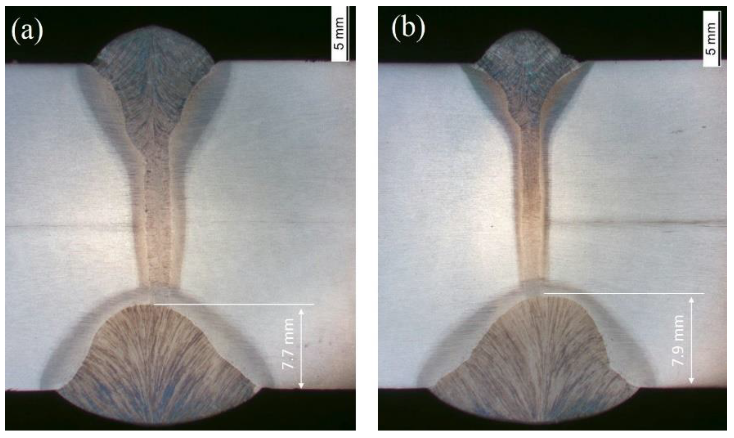
3.1. Hybrid Laser Arc Welding of 30 mm Plates EH36

The parameters of the HLAW process such as the laser power (PL), the arc power (Parc) and the welding speed (vw) were selected so that no full penetration occurs. The HLAW creates a partial penetrated weld that reaches almost to the bottom of the plate. As a comparison of results in Figure 4 shows, such conditions could be achieved within a wide parameter window.
AThe penetration depth of over 25 mm could be reached both for a slow vw = 0.6 m/min (Figure 4a) and for an increased vw = 1.15 m/min (Figure 4b). To compensate for the decrease in the penetration depth when increasing the welding speed, it was necessary to increase the laser power PL from 12 kW up to 15 kW. The arc power was kept constant at Parc = 15.6 kW. The cooling time ∆t8/5 measured at the upper side of the sample was 12.5 s for the HLAW performed with vw = 0.6 m/min and 9.5 s for the HLAW performed with vw = 1.15 m/min.

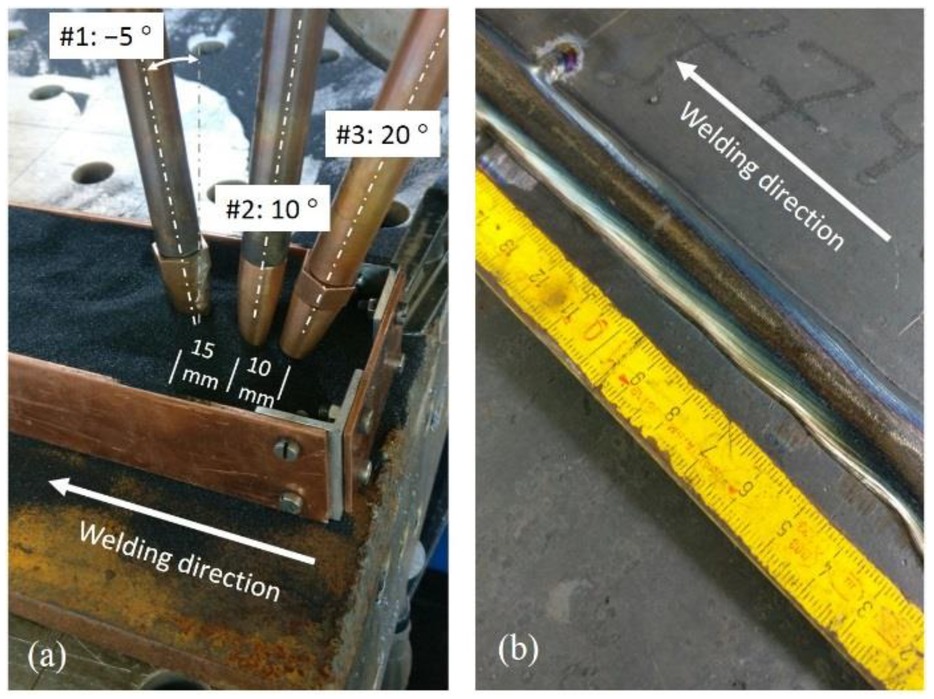
3.2. Submerged Arc Welding of 30 mm Plates EH36
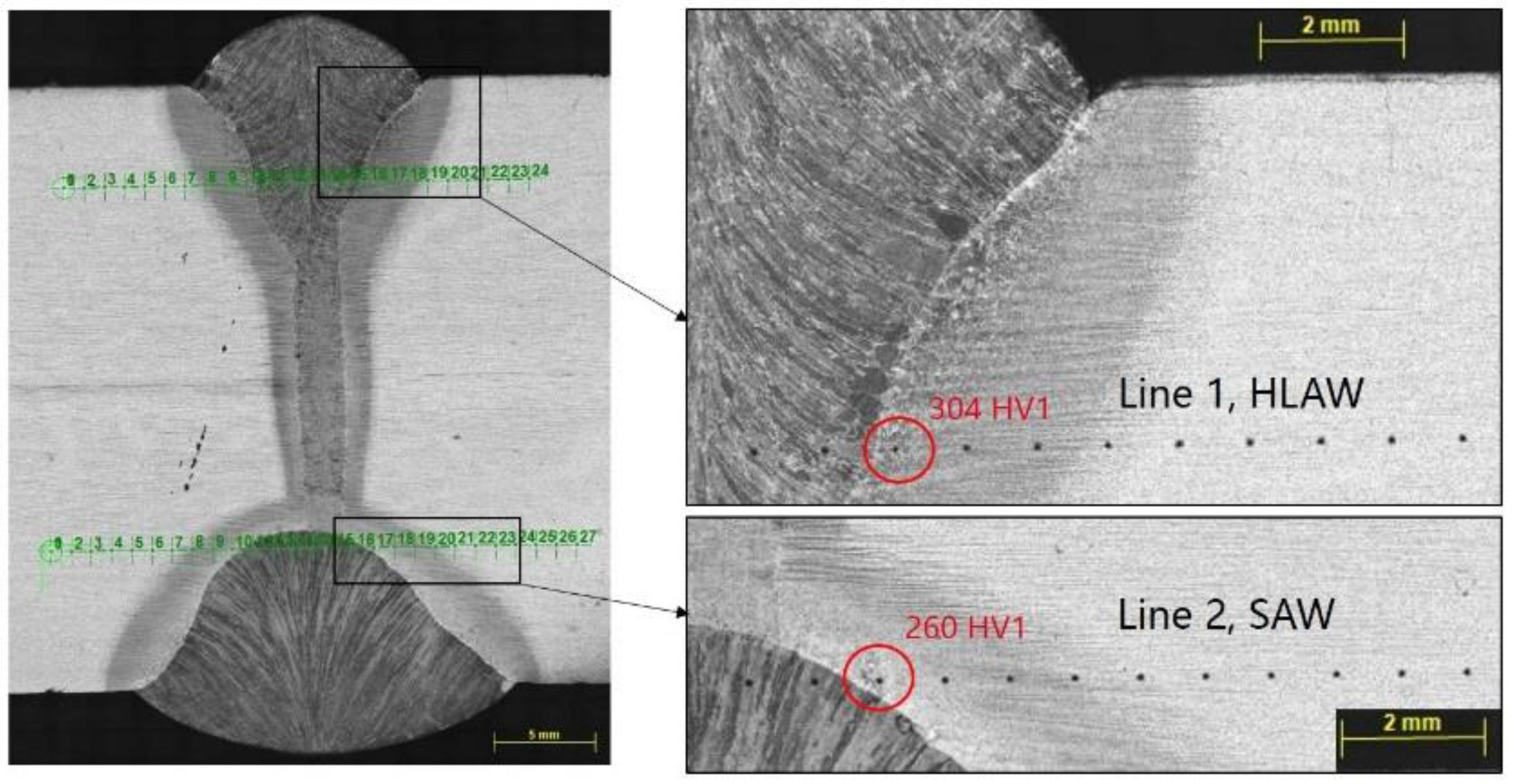
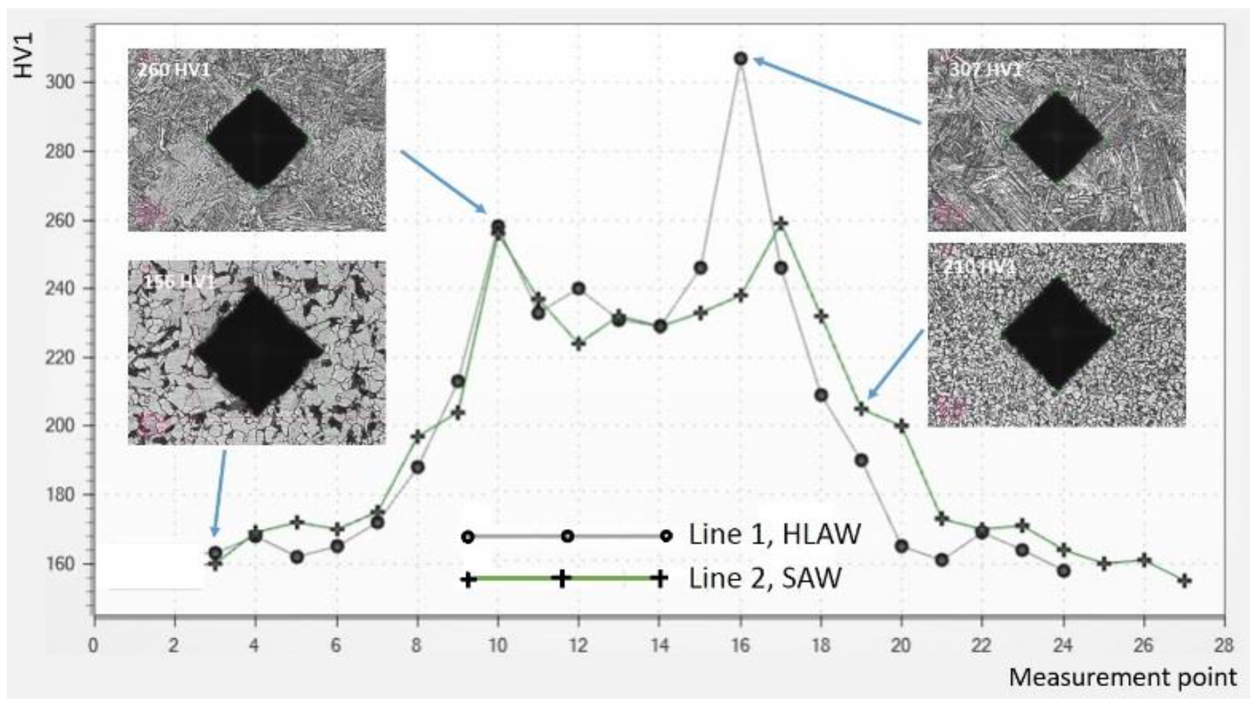
After the EH36 plates were partially welded with HLAW, the SAW welds were performed from the opposite side of the specimens. The parameters of SAW were selected to ensure sufficient penetration depth from one side and, thus, a reliable intersection of the SAW weld and the HLAW weld. From the other side, an economically interesting welding speed of the SAW (vSAW) of above 1 m/min was aimed for. To meet these criteria, a three-wire SAW process was used. The main welding parameters are listed in Table 3. The arrangement of the welding torches to the specimen and the welding result are shown in Figure 5a,b.
The cross-sections in Figure 6a,b show that the partially penetrated HLAW seams are properly overlapped, resulting in a completely closed weld cross-section. The SAW layer is free of undercuts and has a smooth transition from the base metal to the weld metal.
The distances from the contact tip to the weld specimen (stick-out) were 35 mm for all wire electrodes and the distances between the electrodes were set at 15 mm and 10 mm. The calculated heat input of the three-wire SAW process was 3.27 kJ/mm and the deposition rate reached 22.5 kg/h. For comparison, a single-wire SAW provides a typical deposition rate of about 8 kg/h, with conventional welding speeds typically limited to 0.6 m/min [31,32]. The high deposition rate of the three-wire SAW process could be converted into a relatively high welding speed of 1.2 m/min while maintaining the stability of the welding process. The leading electrode was supplied with direct current positive pole (DC+) to achieve the maximum weld penetration depth. The subsequent electrodes 2 and 3 were supplied with alternating current (AC) with a phase shift of 90° to minimize magnetic blowout effects. The trailing angle of −5° of the leading electrode also had a favorable effect on the penetration depth. With the selected welding parameters and torch configuration of the SAW process, a weld penetration depth of at least 7.7 mm was achieved.

3.3. Tests

Welds performed with an HLAW speed of vw = 0.6 m/min (Figure 6a) were selected for testing. The Vickers hardness test HV1 was performed according to DIN EN ISO 6507-1 [33]. Hardness measurements were performed for both the HLAW and the SAW layer. The distance between the hardness indentations was set to 1 mm to avoid any interferences between the results. Figure 7 provides some details on the location of the hardness measurement points in the weld cross-section.
Observing of the individual hardness indentations shows that the highest hardness values of 304 HV1 and 260 HV1 are located in the HAZ of the HLAW and SAW seams, specifically in the fine-grain zone (FGHAZ) near the fusion line. Figure 8 shows the hardness values as hardness profiles. Despite an increase in HAZ hardness by up to 90% above the base material hardness, the maximum allowed hardness levels of 350 HV were not exceeded [34].
The three-point side bend test was performed according to the ASME Section IX and DIN EN ISO 5173 [35]. A total of six bend specimens (three specimens per weld) were tested. The bending force was applied transverse to the welding direction so that the entire weld profile was in tension. The side bend test confirmed the good ductility of the welds. The specified bending angle of 180° was achieved for all specimens. Results of the bend test are shown in Figure 9a–c. After testing, no irregularities, such as lack of fusion, cracks and porosity in any direction, were found in the convex surface of the bent specimens.
The Charpy V-notch (CVN) impact test was performed at the test temperature −20 °C on specimens with dimentions 55 × 10 × 10 mm3 according to DIN EN EN ISO 148-1 [36]. The CVN specimens were extracted from the intersection area of the HLAW with the SAW layer. Figure 10a shows the placement of the CVN specimen in the weld thickness and the position of the V-notch in the center of the HLAW weld. Five CVN specimens after testing and individual impact energy values are shown in Figure 10b.
Four of the five fractured CVN specimens exhibited impact energy above 230 J and indicated a ductile fracture mode with a deviation in the fracture path from WM to BM. This phenomena is known at the narrow laser beam and HLAW welds as “fracture path deviation” (FPD) [37]. Only one fractured CVN sample having an impact energy of 173 J indicated a mixed fracture type. The mean value of the impact energy was 237.4 ± 41 J.

4. Discussion

In this work, a relatively high penetration depth of over 25 mm was achieved at moderate laser powers of 12 kW and 15 kW and welding speeds of 0.6 m/min and 1.15 m/min. Existing research results in the field of laser beam and laser hybrid welding on thick sheets indicate that approximately one kilowatt of laser power is required for one millimeter of penetration depth [38]. This approach can be applied for butt joints with a zero gap and a material thickness up to 20 mm [7]. A linear correlation between laser power and weld penetration depth could not be confirmed for higher wall thicknesses. For example, welding tests with a laser power of 100 kW resulted in a maximum welding depth of 70 mm, which corresponds to a penetration of 0.7 mm per 1 kW of laser power [39]. When using special techniques such as welding under reduced ambient pressure or in a vacuum, the welding penetration depth can be significantly increased [40]. In the present work, a penetration depth of up to 2 mm per one kilowatt of laser power was achieved without using any special welding techniques. This effect is due to the nature of the welding edge. The plasma-cut edge has a specific cutting profile that guarantees a V-shaped gap between the weld pieces [30]. The laser beam penetrates through a butt joint with such a gap much more easily than through a full material. This observation was also confirmed for the laser-cut edges, where HLAW could be performed in one pass on 25 mm thick steel with only 14 kW of laser power [41]. Thus, the plasma-cut edge can be seen as advantageous for industrial practice. On the one hand, the costly mechanical machining of the weld edges is not necessary. On the other hand, higher productivity can be achieved due to the increased penetration depth.
Although all tested CVN specimens showed sufficient averaged impact energy of 237.4 J, the dispersion of individual values ±41 J was relatively high. This is due to the fact that, with the same test parameters, the specimens behaved differently in the impact test. Such differences in the impact energy of the HLAW welds can be explained by the narrowness of the FZ as well as the grade of mechanical properties mismatch between the FZ, HAZ and BM, which was indirectly confirmed by hardness measurements. The highest values obtained for the impact energy are due to the fact that the fracture occurs with FPD, with some volume of BM involved in the deformation process. This observation is consistent with the results of the study [37], in which the authors point out some reasons for the FPD formation. These are the narrowness of the FZ and low volume of the WM involved in the deformation process, asymmetry of the stress concentrator due to the specific FZ shape and the presence of zones in the weld with softer metal. These facts favor the crack propagating directly from the notch root into a softer BM throughout the thickness of the specimen. In some cases, the fracture occurs through the center of the WM without FPD. However, one of the conditions for this is an exact placement of the notch tip in the center of the FZ, which is not always possible when machining the CVN specimen.
In this study, HLAW tests were performed as partial penetration welding. It is known from the previous studies that partially penetrated welds are more susceptible to the formation of the solidification cracks and pores than fully penetrated welds [42]. These imperfections typically occur in the middle or in the root region of the weld and are the result of an interaction between metallurgical, geometric and thermomechanical factors. As the results of the present work show, any defects in the root of the HLAW seam can be reliably remelted by the SAW layer, so that they no longer have any significance for the functional safety of the component. The occurrence of crystallization cracks in the center of the weld can be counteracted by adjusting welding parameters such as arc power, defocusing of the laser beam and welding speed [43]. Since the aim of the present work was to demonstrate the basic feasibility of the welding method, these aspects were not investigated in depth. They are the subject of the currently ongoing investigations.

5. Conclusions

Thirty mm thick sheets of shipbuilding steel EH36 were butt welded in a two-run technique using HLAW and SAW processes. The seam cross-section was completely filled with a 25 mm deep HLAW layer and an approx. 8 mm deep SAW opposing layer. The intersection of both layers was 3 mm. Thus, the potentially defective root of the partial penetrated laser hybrid weld could be reliably remelted by the SAW layer.
A high stability of the welding process with regard to the preparation quality of the weld edges could be demonstrated. Thirty mm thick plates with plasma-cut edges could be welded without defects and with sufficient mechanical-technological properties.
The proposed method does not require mechanical processing of the weld edges and there is no need for weld pool support. Therefore, the application of the proposed welding method seems to be attractive for industrial use.

Author Contributions

Conceptualization, S.G, M.B., A.G. and M.R.; Formal analysis, A.M.; Investigation, A.M.; Methodology, S.G. and A.G.; Project administration, M.R.; Writing—original draft, S.G. and A.M.; Writing—review & editing, M.B., A.G. and M.R. All authors have read and agreed to the published version of the manuscript.

Funding

This work was supported by the Research Association for Steel Application (FOSTA), the Federation of Industrial Research Associations (AiF), and the German Federal Ministry for Economic Affairs and Climate Action (BMWK Bundesministerium für Wirtschaft und Klimaschutz) (Project 21532N, “Combination of laser-hybrid welding and narrow-gap submerged arc welding for thick-walled components”).

Conflicts of Interest

The authors declare no conflict of interest.

References

  1. Schaumann, P.; Stranghöner, N.; Flügge, W. Stahlanwendungsforschung in der Windenergie. FOSTA. Available online: https://www.stahlforschung.de/media/50j-fosta-windenergie_1.pdf (accessed on 6 July 2022).
  2. Shirahata, H.; Nakashima, K.; Inoue, T.; Ishida, K.; Funatsu, Y.; Okawa, T.; Yanagita, K.; Inami, A.; Minagawa, M. YP 460 N/mm2 class heavy thick plate with excellent brittle crack arrestability for mega container ships. Nippon Steel Sumitomo Met. Tech. 2015, 110, 25–29. [Google Scholar]
  3. Um, K.K.; Kim, S.H.; Kang, K.B.; Park, Y.H.; Kwon, O. High performance steel plates for shipbuilding ap-plications. In Proceedings of the Eighteenth International Offshore and Polar Engineering Conference, Vancouver, BC, Canada, 6–11 July 2008. [Google Scholar]
  4. Steel Plates for Shipbuilding, JFE, Japan. Available online: https://www.jfe-steel.co.jp/en/products/plate/catalog/c1e-011.pdf (accessed on 3 July 2022).
  5. Malin, V.Y. The State-of-the Art of Narrow Gap Welding Part II. Welding J. 1983, 62, 37–46. [Google Scholar]
  6. Gook, S.; Gumenyuk, A.; Rethmeier, M. Weld seam formation and mechanical properties of girth welds performed with laser-GMA-hybrid process on pipes of grade X65. In Proceedings of the International Congress on Applications of Lasers & Electro-Optics, Anaheim, CA, USA, 26–30 September 2010; Volume 2010, pp. 62–69. [Google Scholar]
  7. Rethmeier, M.; Gook, S.; Lammers, M.; Gumenyuk, A. Laser-Hybrid Welding of Thick Plates up to 32 mm Using a 20 kW Fibre Laser. Q. J. Jpn. Weld. Soc. 2009, 27, 74s–79s. [Google Scholar] [CrossRef] [Green Version]
  8. Üstündağ, Ö.; Gook, S.; Gumenyuk, A.; Rethmeier, M. Hybrid laser arc welding of thick high-strength pipeline steels of grade X120 with adapted heat input. J. Mater. Process. Technol. 2019, 275, 116358. [Google Scholar] [CrossRef]
  9. Sørensen, C.; Nissen, A.; Brynning, C.; Nielsen, J.; Schøn, R.; Malefijt, R.; Kristiansen, M. Double-sided Hybrid Laser-Arc Welding of 25 mm S690QL High Strength Steel. IOP Conf. Ser. Mater. Sci. Eng. 2021, 1135. [Google Scholar] [CrossRef]
  10. DIN EN 10225-1; Weldable Structural Steels for Fixed Offshore Structures-Technical Delivery Conditions-Part 1: Plates. Beuth Verlag: Beuth, Germany, 2019.
  11. Turichin, G.; Kuznetsov, M.; Pozdnyakov, A.; Gook, S.; Gumenyuk, A.; Rethmeier, M. Influence of heat input and preheating on the cooling rate, microstructure and mechanical properties at the hybrid laser-arc welding of API 5L X80 steel. Procedia CIRP 2018, 74, 748–751. [Google Scholar] [CrossRef]
  12. Wang, G.; Wang, J.; Yin, L.; Hu, H.; Yao, Z. Quantitative Correlation between Thermal Cycling and the Microstructures of X100 Pipeline Steel Laser-Welded Joints. Materials 2019, 13, 121. [Google Scholar] [CrossRef] [PubMed] [Green Version]
  13. Knoop, F.M.; Bremer, S.; Flaxa, V.; Scheller, W.; Liedtke, M. The processing of helical-welded large diameter pipes of grade X80 with 23.7 mm wall thickness and their properties. In Proceedings of the International Seminar on Welding of High Strength Pipeline Steels, Araxa, Brazil, 28–30 November 2011; pp. 209–229. [Google Scholar]
  14. Frantov, I.; Permyakov, I.; Bortsov, A. Improved weldability and criterion for reliability of high strength pipes steels. In Proceedings of the International Seminar on Welding of High Strength Pipeline Steels, Araxa, Brazil, 28–30 November 2011; pp. 247–260. [Google Scholar]
  15. Shang, C.J.; Wang, X.X.; Liu, Q.Y.; Fu, J.Y. Weldability of high niobium X80 pipeline steel. In Proceedings of the International Seminar on Welding of High Strength Pipeline Steel, Araxa, Brazil, 28–30 November 2011; Volume 435, p. 453. [Google Scholar]
  16. Roland, F.; Manzon, L.; Kujala, P.; Brede, M.; Weitzenbock, J. Advanced Joining Techniques in European Shipbuilding. J. Ship Prod. 2004, 20, 200–210. [Google Scholar] [CrossRef]
  17. Üstündag, Ö.; Avilov, V.; Gumenyuk, A.; Rethmeier, M. Full penetration hybrid laser arc welding of up to 28 mm thick S355 plates using electromagnetic weld pool support. J. Phys. Conf. Ser. 2018, 1109, 012015. [Google Scholar] [CrossRef]
  18. Üstündag, Ö.; Gumenyuk, A.; Rethmeier, M. Single-pass Hybrid Laser Arc Welding of Thick Materials Using Electromagnetic Weld Pool Support. In Proceedings of the International WLT-Conference on Lasers in Manufacturing, Munich, Germany, 23–26 May 2019. [Google Scholar]
  19. Wahba, M.; Mizutani, M.; Katayama, S. Single pass hybrid laser-arc welding of 25 mm thick square groove butt joints. Mater. Des. 2016, 97, 1–6. [Google Scholar] [CrossRef]
  20. Reisgen, U.; Olschok, S.; Engels, O. Laser beam submerged arc hybrid welding: A novel hybrid welding process. J. Laser Appl. 2018, 30, 042012. [Google Scholar] [CrossRef] [Green Version]
  21. Üstündağ, Ö.; Gook, S.; Gumenyuk, A.; Rethmeier, M. Mechanical Properties of Single-pass Hybrid Laser Arc Welded 25 mm Thick-walled Structures Made of Fine-grained Structural Steel. Procedia Manuf. 2019, 36, 112–120. [Google Scholar] [CrossRef]
  22. Frostevarg, J.; Heussermann, T. Dropout formation in thick steel plates during laser welding. In Proceedings of the IIW International Conference on High Strength Materials–Challenges and Applications, Helsinki, Finland, 2–3 July 2015. [Google Scholar]
  23. Suder, W.; Ganguly, S.; Williams, S.; Yudodibroto, B. Root stability in hybrid laser welding. J. Laser Appl. 2017, 29, 022410. [Google Scholar] [CrossRef] [Green Version]
  24. Bunaziv, I.; Dørum, C.; Nielsen, S.E.; Suikkanen, P.; Ren, X.; Nyhus, B.; Eriksson, M.; Akselsen, O.M. Root formation and mechanical properties in laser keyhole welding of 15 mm thick HSLA steel. IOP Conf. Ser. Mater. Sci. Eng. 2021, 1135. [Google Scholar] [CrossRef]
  25. Üstündağ, Ö.; Fritzsche, A.; Avilov, V.; Gumenyuk, A.; Rethmeier, M. Hybrid laser-arc welding of thick-walled ferromagnetic steels with electromagnetic weld pool support. Weld. World 2018, 62, 767–774. [Google Scholar] [CrossRef]
  26. Avilov, V.V.; Gumenyuk, A.; Lammers, M.; Rethmeier, M. PA position full penetration high power laser beam welding of up to 30 mm thick AlMg3 plates using electromagnetic weld pool support. Sci. Technol. Weld. Join. 2012, 17, 128–133. [Google Scholar] [CrossRef]
  27. BV NR 216 DT R07 E; BV Rules on Materials and Welding for the Classification of Marine Units. Bureau Veritas: Paris, France, 2018; Volume 33.
  28. Lloyd’s Register Group. Rules for the Manufacture, Testing and Certification of Materials; Lloyd’s Register: London, UK, 2017. [Google Scholar]
  29. DNVGL-CG-0287; Hybrid Laser-Arc Welding. DNVGL: Oslo, Norway, 2015.
  30. Üstündağ, Ö.; Bakir, N.; Gook, S.; Gumenyuk, A.; Rethmeier, M. Hybrid laser-arc welding of laser- and plasma-cut 20-mm-thick structural steels. Weld. World 2022, 66, 507–514. [Google Scholar] [CrossRef]
  31. Layus, P.; Kah, P.; Gezha, V. Advanced submerged arc welding processes for Arctic structures and ice-going vessels. Proc. Inst. Mech. Eng. Part B J. Eng. Manuf. 2016, 232, 114–127. [Google Scholar] [CrossRef]
  32. Chandel, R.; Seow, H.; Cheong, F. Effect of increasing deposition rate on the bead geometry of submerged arc welds. J. Mater. Process. Technol. 1997, 72, 124–128. [Google Scholar] [CrossRef]
  33. DIN EN ISO 6507-1; Metallic Materials-Vickers Hardness Test-Part 1: Test Method. Deutsches Institut fur Normung E.V. (DIN): Beuth, Germany, 2022.
  34. DIN EN ISO 15614-1; Specification and Qualification of Welding Procedures for Metallic Materials-Welding Procedure Test-Part 1: Arc and Gas Welding of Steels and Arc Welding of Nickel and Nickel Alloys. Deutsches Institut fur Normung E.V. (DIN): Beuth, Germany, 2020.
  35. DIN EN ISO 5173; Destructive Tests on Welds in Metallic Materials—Bend Tests. Deutsches Institut fur Normung E.V. (DIN): Beuth, Germany, 2021.
  36. DIN EN ISO 148-1; Metallic Materials-Charpy Pendulum Impact Test-Part 1: Test Method. Deutsches Institut fur Normung E.V. (DIN): Beuth, Germany, 2017.
  37. Ohata, M.; Morimoto, G.; Fukuda, Y.; Minami, F.; Inose, K.; Handa, T. Prediction of ductile fracture path in Charpy V-notch specimen for laser beam welds. Weld. World 2015, 59, 667–674. [Google Scholar] [CrossRef]
  38. Paes, L.E.D.S.; Pereira, M.; Weingaertner, W.L.; Scotti, A.; Souza, T. Comparison of methods to correlate input parameters with depth of penetration in LASER welding. Int. J. Adv. Manuf. Technol. 2018, 101, 1157–1169. [Google Scholar] [CrossRef]
  39. Kawahito, Y.; Wang, H.; Katayama, S.; Sumimori, D. Ultra high power (100 kW) fiber laser welding of steel. Opt. Lett. 2018, 43, 4667–4670. [Google Scholar] [CrossRef] [PubMed]
  40. Katayama, S.; Yohei, A.; Mizutani, M.; Kawahito, Y. Development of Deep Penetration Welding Technology with High Brightness Laser under Vacuum. Phys. Procedia 2011, 12, 75–80. [Google Scholar] [CrossRef] [Green Version]
  41. Farrokhi, F.; Larsen, R.M.; Kristiansen, M. Single-pass Hybrid Laser Welding of 25 mm Thick Steel. Phys. Procedia 2017, 89, 49–57. [Google Scholar] [CrossRef]
  42. Gebhardt, M.O.; Gumenyuk, A.; Rethmeier, M. Solidification cracking in laser GMA hybrid welding of thick-walled parts. Sci. Technol. Weld. Join. 2013, 19, 209–213. [Google Scholar] [CrossRef]
  43. Bakir, N.; Üstündağ, Ö.; Gumenyuk, A.; Rethmeier, M. Experimental and numerical study on the influence of the laser hybrid parameters in partial penetration welding on the solidification cracking in the weld root. Weld. World 2020, 64, 501–511. [Google Scholar] [CrossRef] [Green Version]
Figure 1. A 30 mm thick weld specimen EH36 with plasma cut edges.
Jmmp 06 00084 g001
Figure 2. Edge profile of plasma-cut plate made of low carbon high strength steel [30].
Jmmp 06 00084 g002
Figure 3. HLAW system: (a) process configuration; (b) experimental setup with temperature measurement system.
Jmmp 06 00084 g003
Figure 4. Cross-sections of partial penetration HLAW seams performed with different process parameters: (a) lower welding speed und laser power; (b) higher welding speed und laser power.
Jmmp 06 00084 g004
Figure 5. Submerged arc welding of 30 mm plates EH36: (a) welding torch configuration; (b) outer appearance of the three-wire SAW weld.
Jmmp 06 00084 g005
Figure 6. Cross-sections of partial penetration HLAW seams with SAW as opposite layers: (a) HLAW layer performed with vw = 0.6 m/min; (b) HLAW layer performed with vw = 1.15 m/min.
Jmmp 06 00084 g006
Figure 7. Location of the HV1 measurement points in the cross-section of the weld.
Jmmp 06 00084 g007
Figure 8. Hardness profiles of HLAW and SAW layers.
Jmmp 06 00084 g008
Figure 9. Results of site bend test: (a) bent specimen in the three-point bending machine; (b) top view of bent specimens; (c) convex surface of the bent specimen.
Jmmp 06 00084 g009
Figure 10. Results of CVN impact test: (a) position of the CVN specimen in relation to the weld seam; (b) CVN specimens after testing at −20 °C.
Jmmp 06 00084 g010
Table 1. Chemical composition of used steel EH36, shown in wt%.
CSiMnPSAlNNb
0.110.211.210.0170.0050.0330.0050.003
VTiCuCrNiMoFeCeq *
0.0710.0170.010.030.010.001bal.0.33
* Ceq = C + Mn/6 + (Ni + Cu)/15 + (Cr + Mo + V)/5.
Table 2. Mechanical properties of used steel EH36.
Charpy at −20 °C
in J
Yield Strength
in MPa
Ultimate Tensile Strength
in MPa
Elongation
in %
28350355522
Table 3. Parameters of three-wire SAW process.
vsaw in
m/min
Electrode 1 (DC+)Electrode 2 (AC)Electrode 3 (AC)
I in AU in Vvf in m/minI in AU in Vvf in m/minI in AU in Vvf in m/min
1.2970292.3 ± 0.2640340.9 ± 0.1430360.6 ± 0.1
Publisher’s Note: MDPI stays neutral with regard to jurisdictional claims in published maps and institutional affiliations.

