1. Introduction
With the continuous advancement of modern technology, the application range of UAVs is becoming increasingly widespread. In recent years, UAVs have been appearing more frequently in people’s sight. During UAV flights, surveying tasks need to be completed in preparation for future navigation inspections. The SLAM process in the UAV system requires high real-time performance, especially in terms of CPU information processing speed, which has become the main research direction at present. Based on the type of sensor used, SLAM systems can be categorized as visual SLAM, lidar SLAM, and multi-sensor fusion SLAM.
The camera offers abundant visual information at a low cost and in a compact form factor, enabling robot localization and navigation. However, purely visual SLAM performance often deteriorates in low-textured environments. To address this issue, researchers have combined points with other geometric entities such as lines as lines [
1] or planes [
2]. In human-made environments, a pose-graph optimization strategy can be used to take advantage of structural constraints such as parallelism or orthogonality of walls. Another well-known approach for reducing rotation drift is to adopt the Manhattan World (MW) assumption [
3]. However, most of the methods discussed above use RGB-D cameras in human-made environments, which may not be universally applicable. Moreover, the accuracy of the system depends heavily on the estimation of the ground plane and Manhattan Axes (MA). Recently, with the development of deep learning, a combined system of SLAM and a Convolutional Neural Network (CNN) has emerged. In [
4], a table retrieval method is proposed for data association and loop closure using semantic information in a dynamic environment. Each landmark is associated with its own semantic and location information to improve the accuracy of the system.
To address the limitations of purely visual SLAM, the fusion of vision and IMU data have become mainstream. The IMU is primarily used to measure acceleration and rotational motion, providing high-frequency and outlier-free inertial measurements. However, the IMU’s long-term operation may result in significant accumulated drift, which necessitates the initialization of all IMU parameters and real-time optimization in the later stages. This is critical for visual–inertial odometry (VIO) and visual–inertial SLAM systems, and researchers are actively seeking ways to quickly complete the initialization of the IMU and suppress its noise and bias. Currently, the initialization methods of VIO systems can be broadly categorized into two main approaches: loosely coupled [
5,
6] and tightly coupled [
7]. The loosely coupled approach involves separate initialization processes for the IMU and the camera, followed by minimizing the distance between their poses. In VINS-Mono [
5], keyframes and map points are initially obtained using visual odometry, and IMU parameters are optimized through aligning the IMU pre-integrated rotation with visual measurements by covariance propagation of the error term. However, this approach estimates the velocity as an unknown variable and overlooks the accelerometer bias, leading to incomplete initialization information. On the other hand, ORB-SLAM3 [
6] is a visual–inertial tightly coupled system that employs MAP estimation to estimate scale, gravity direction, biases, and velocity during IMU initialization, while the tightly coupled approach directly establishes constraints between the camera and IMU during the initialization process to optimize various parameters. OpenVINS [
7] is a tightly coupled initialization approach that leverages camera poses to establish visual constraints, enabling the estimation of initial velocity, gravity, and three-dimensional coordinates of feature points. Subsequently, multiple-frame velocity and position relationships are obtained through first-order and second-order integration, respectively. BASALT [
8] employs a two-level SLAM system that optimizes the noise and bias of the IMU in both stages. In contrast to other systems, it does not directly utilize the pre-integrated IMU measurements in the mapping stage. Instead, it extracts short-term visual–inertial tracking information from the marginalized information of the VI-odometry stage. This approach not only reduces the dimensionality of the global optimization problem but also enhances the accuracy of the optimization results. GVINS [
9] employs a coarse-to-fine approach to initialize GNSS visual–inertial states using MAP estimation and integrates their raw measurements within a probabilistic framework. It is capable of providing drift-free 6-DoF global pose estimation in complex environments where GNSS signals may be obstructed or entirely unavailable.
One of the challenges in developing SLAM systems is ensuring algorithm robustness and real-time performance while working with limited computing resources, such as cheap and low-performance processors. This is especially important for battery-powered robots, where computational efficiency is crucial for extending the robot’s endurance. To address these challenges, researchers have proposed various approaches. For example, Ref. [
10] uses a direct method to initialize the system and tracks non-keyframes for state estimation at the front-end. At the back-end, sliding window and marginalization are adopted to limit the number of keyframes and perform nonlinear optimization. Similarly, FastORB-SLAM [
11] tracks keypoints between incoming frames without computing descriptors, exploiting motion smoothness and constraints on epipolar geometry to refine the correspondence. ORB-SLAM2S [
12] includes a lightweight front-end that uses a sparse optical flow method for non-keyframes and descriptors, achieving faster speed performance compared to ORB-SLAM2. However, these methods often replace ORB features with direct methods and optical flow methods to track feature points, which can lead to reduced system accuracy if feature points are not extracted properly.
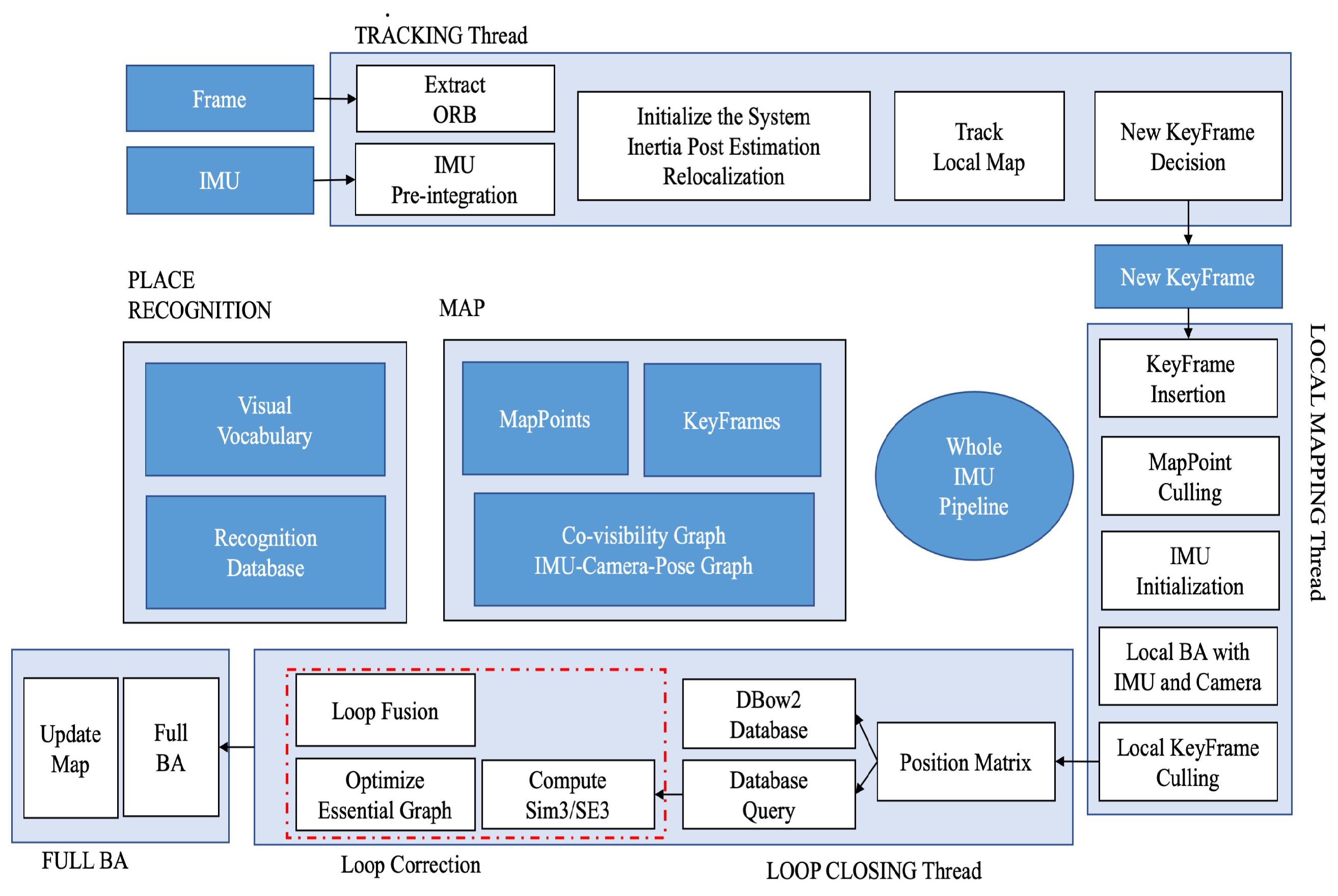
Our laboratory is developing an inspection robot that relies on the Robot Operating System (ROS) and object detection algorithms to achieve mapping and monitoring. Endurance and real-time tracking are key factors for inspection robots. Therefore, we propose a lightweight stereo-inertial SLAM based on nonlinear optimization and feature tracking, which achieves fast tracking, better robustness, and a lower CPU load. The overall system architecture is shown in
Figure 1. Our three main contributions focus on speeding up tracking, reducing CPU consumption, and maintaining system accuracy. The main contributions are summarized as follows:
A coarse-to-fine optimization approach. Coarse optimization is for faster IMU initialization to replace the constant velocity model and speed up the tracking process, while fine optimization ensures localization accuracy.
A novel visual–inertial pose graph as an observer decides which variables need to be optimized to prevent over-optimization.
Fusion of IMU data with loop closure to further reduce CPU load.
The rest of the paper is structured as follows: in
Section 2, we introduce the state-of-the-art relevant systems.
Section 3 is the main contribution and framework of the system. The experiment setup and comparison with other systems are given in
Section 4. The last section covers the conclusions of this work.
2. Related Work
In recent years, visual SLAM has gained increasing attention from researchers due to advancements in sparse nonlinear optimization theory and computer performance. Most visual SLAMs rely on point features and MAP estimation because of their general applicability. In the feature-based method, the system’s robustness and localization accuracy are improved by minimizing the feature reprojection error, while photometric Bundle Adjustment (BA) is used to optimize the pose by minimizing the photometric error of a set of pixels in the direct method. Cameras provide rich visual information at low cost. However, point features have several drawbacks. First, point features extracted by vision sensors are highly sensitive to environmental conditions and fail to track when the texture is poor or the image is blurred. Moreover, they are vulnerable to illumination changes. Finally, point features are sparse, making them challenging to use in robot path planning.
SLAM involves three types of data association [
13]: short-term data association for feature point tracking, medium-term data association for bundle adjustment in local maps, and long-term data association for loop closure. This approach is followed by most current visual SLAM systems. Nonlinear optimization methods have been shown to have better accuracy than filtering, so the current mainstream approach is to select representative frames (keyframes) for input into backend optimization. The keyframe-based approach provides better accuracy with less computation, and has become an important standard for current SLAM systems. PTAM [
14] is a representative system for keyframes, with two parallel threads for camera pose tracking and mapping to achieve short-term and medium-term data association. ORB-SLAM [
15,
16] has three parallel threads for tracking, local mapping, and loop closing, representing short-term, medium-term, and long-term data association, respectively. ORB features are used for short-term data association to compute the pose between frames. Medium-term data association uses keyframes and map points to minimize reprojection errors with bundle adjustment, while the loop closure thread uses the bag-of-words library DBoW2 [
17] for long-term data association. These methods have greatly improved the accuracy of ORB-SLAM.
Multi-sensor fusion systems can significantly improve state estimation accuracy and robustness due to the complementarity between sensors. Adding an IMU can solve the problem of scale in monocular SLAM, where the image frame lacks depth information of the environment. Most visual–inertial fusion SLAM systems are tightly coupled and classified as either filter-based or optimization-based systems. The earliest multi-sensor fusion SLAM, MSCKF [
18], relies on the feature method and adopts the EKF filtering method for optimization, adding camera poses at different times to the state vector. On the other hand, OKVIS [
19] is the most representative system based on the nonlinear optimization method and uses keyframes, relying on the error propagation model to optimize the inertial. Some previous methods, such as [
20,
21], have limitations in their solution process or initialization scale accuracy. Recently, Ref. [
22] proposed a robust stereo inertial odometry based on self-supervised feature points, using an improved multi-task CNN to extract feature points and incorporating an IMU to deal with rapid camera movements.
3. System Overview
The ORB-SLAM3’s three threads can be taxing for certain processors and lack real-time monitoring of optimized inertial parameters. Therefore, our proposed system builds upon it with further refinement to improve real-time performance and decrease computation load, which is especially beneficial for low-end Intel Next Unit of Computing (NUC). We chose stereo because it directly measures scale without the need for additional computation and optimization via inertial information. According to our experiments (presented in
Section 4.1), the stereo-inertial system is more accurate than the monocular-inertial system. The system is divided into three threads: tracking, local mapping, and loop closure, with each thread serving a specific function, which will be discussed later. It is worth noting that some of the formulas presented are not a contribution of this work, but are mainly from [
23].
3.1. Coarse-to-Fine IMU Optimization
3.1.1. IMU Pre-Integration
From the parameters of inertial measurement between frame
and
, the position, velocity, and rotation of the object are expressed by
where
,
are, respectively, the position and velocity of
frame in the world reference.
is a quaternion which represents the transformation from
frame to the world reference, ⨂ denotes the transformation operation,
,
represent angular velocity and acceleration in
frame reference, respectively,
g is the gravity vector,
t is the time variation between frame
and
.
Due to the high sampling frequency of the IMU, the IMU pre-integration method can convert the integration of multiple measurement values into a single one, which improves the calculation efficiency. Transform Equations (
1)–(
3) according to Equation (
4):
From Equations (
5)–(
7), the IMU’s pre-integration between frame
and
can be expressed as follows:
where
,
, and
are the position, velocity, and rotation variation, respectively.
3.1.2. Coarse IMU Optimization
Since both the accelerometer and gyroscope of IMU have noise and bias, it will have a bad influence on the measurement results. We set a covariance matrix
to contain
,
, and
. Residual models can be used for IMU initialization and visual–inertial BA optimization.
In local mapping thread, we adopt a maximum a posteriori estimation to estimate the IMU variables as a coarse but fast optimization. Assuming that all variables are independent, the noise of the variables follows a Gaussian distribution with a mean of zero. The scale of the stereo camera is known and does not require optimization. The estimated parameters are as follows:
where
represents the rotation matrix from ENU reference to the world reference. The direction of gravity in ENU is (0, 0, g).
are the biases of the accelerometer and gyroscope, respectively.
denotes the up-to-scale velocity vector accumulation from the first to current frame. The parameters in
are optimized by inertial-only MAP:
where
is likelihood, and
stands for prior knowledge.
MAP estimation can further transform the graph optimization problem, using the parameters in
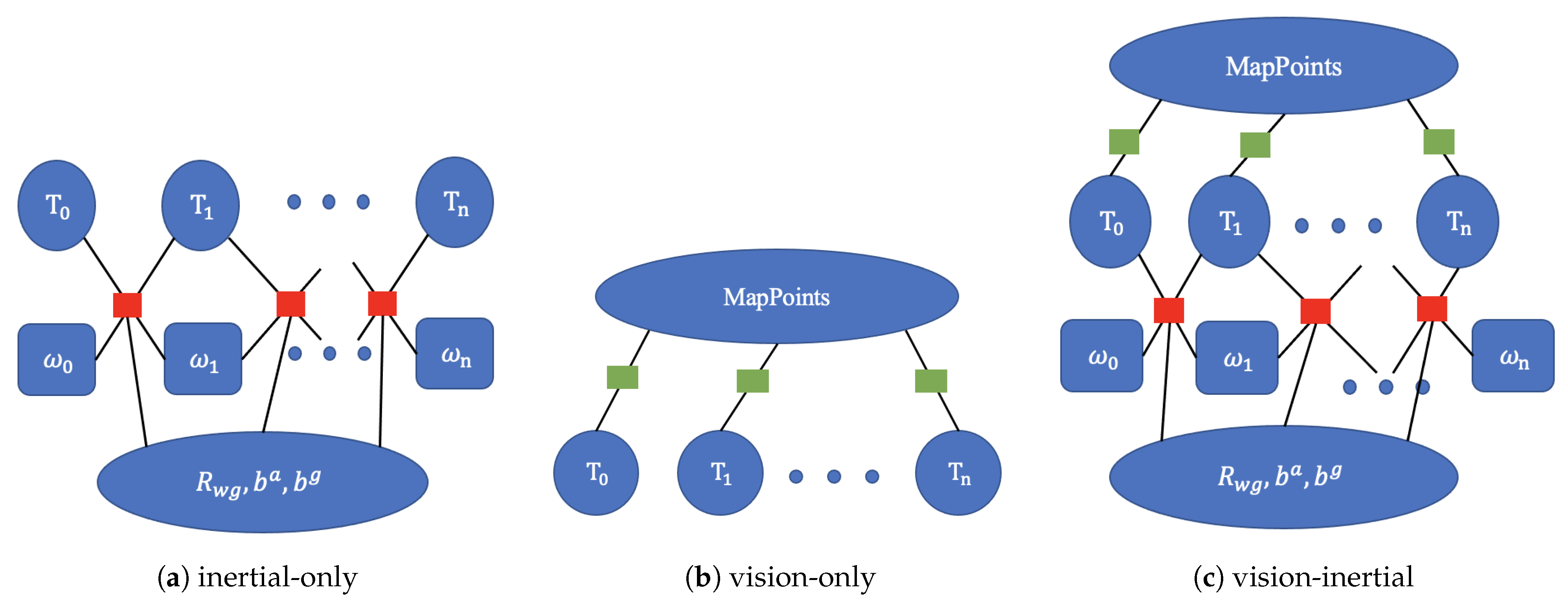
as vertices and gyroscope bias, acceleration bias, velocity, etc., as edges. The inertial residual model is then adopted to minimize the distance between IMU biases and zero, as shown in
Figure 2a. This approach to IMU initialization is a coarse optimization method. Compared with [
19,
20,
21], it is faster. Furthermore, feature point matching between consecutive frames is time-consuming, with a maximum time complexity of
(where
N is the number of feature points). However, this problem can be addressed by using optimized IMU data for the initial estimation of the camera pose, rather than relying on the constant velocity model. By leveraging IMU information, the feature points from the previous frame are projected onto the pixel plane of the current frame, and matching feature points can only be found within a few pixels, thereby speeding up feature point search and improving tracking performance.
When the system starts, the pure vision module is required to initialize and generate map point clouds, and the world reference may not be aligned with the ENU, which will cause serious errors in the IMU integration and affect the positioning accuracy. After IMU initialization is completed, the optimized
is used to align the Z axis of the world reference with the direction of the gravity G to ensure more accurate IMU preintegration. Finally, the system obtains all keyframes in the map, adjusts their poses according to Equation (
17), and completes the transformation to the new world reference.
3.1.3. Fine IMU Optimization
When IMU initialization has not started, pure visual MAP estimation is adopted, which is converted into graph optimization as shown in
Figure 2b. The system runs in pure vision mode for 2 s to initialize the entire system, generating keyframes at 4 Hz and 3D map points. We define a local window to contain the co-visible keyframes and other keyframes that can observe the 3D map points in the current keyframe. Then, reprojection error is used in the local window to optimize the pose and 3D map points.
where
is the observation of pixel
j in the
frame,
SE(3) represents the transformation between the world reference and
frame, ⨂ is the transformation operation of SE(3) group over
elements, and
stands for the 3D map point
j.
To judge whether IMU variables have good initialization, we introduce a vision–inertial pose graph:
where
is the pose in the IMU reference, and
stands for the pose in the camera reference.
When there is no bias, Equation (
19) must be equal to the identity matrix since the transform between frames computed by the IMU and the camera should be the same. However, during system operation, IMU parameters are affected by noise such as temperature. Therefore, we set a threshold, and when
is within the threshold range, indicating that the IMU parameters do not need to be optimized in this frame, the visual-only MAP estimation (Equation (
18)) is performed between the current keyframe and its local keyframes. Otherwise, a joint visual–inertial MAP estimation as Equation (
20) is used to combine the inertial residual and visual residual to further refine the solution (
Figure 2c). This approach is a finer optimization method for inertial variables and camera poses. Multiple BA methods can be used to reduce the time of back-end optimization and prevent some parameters from being over-optimized.
where
is the current keyframe and its local keyframe,
stands for the inertial residual,
represents the visual residual,
is the robust kernel which is used to reduce the influence of wrong matching.
3.2. Inertial and Loop Closing
In the loop closing thread, the DBoW2 word-bag library is utilized to solve the position recognition problem, which converts the features in keyframes into bag-of-words vectors and queries the DBoW2 database to retrieve the most similar keyframes
As the SLAM system operates, the number of keyframes gradually increases, leading to an increase in query time and CPU energy consumption. This can be problematic for some embedded systems. To address this issue, we propose a new method for loop closure detection that uses IMU for rough judgment. Our inspiration for this method comes from [
22,
23,
24], where the incremental consistent measurement set maximization (PCM) method is proposed to check the quality of loop closures and remove outliers after bag-of-words vectors matching. This post-operation effectively reduces the occurrence of false fusion, but it also increases the amount of calculation required. Our method differs in that it performs coarse loop closure detection before bag-of-words database traversal. This reduces the number of queries to the database, thereby reducing the burden on the CPU.
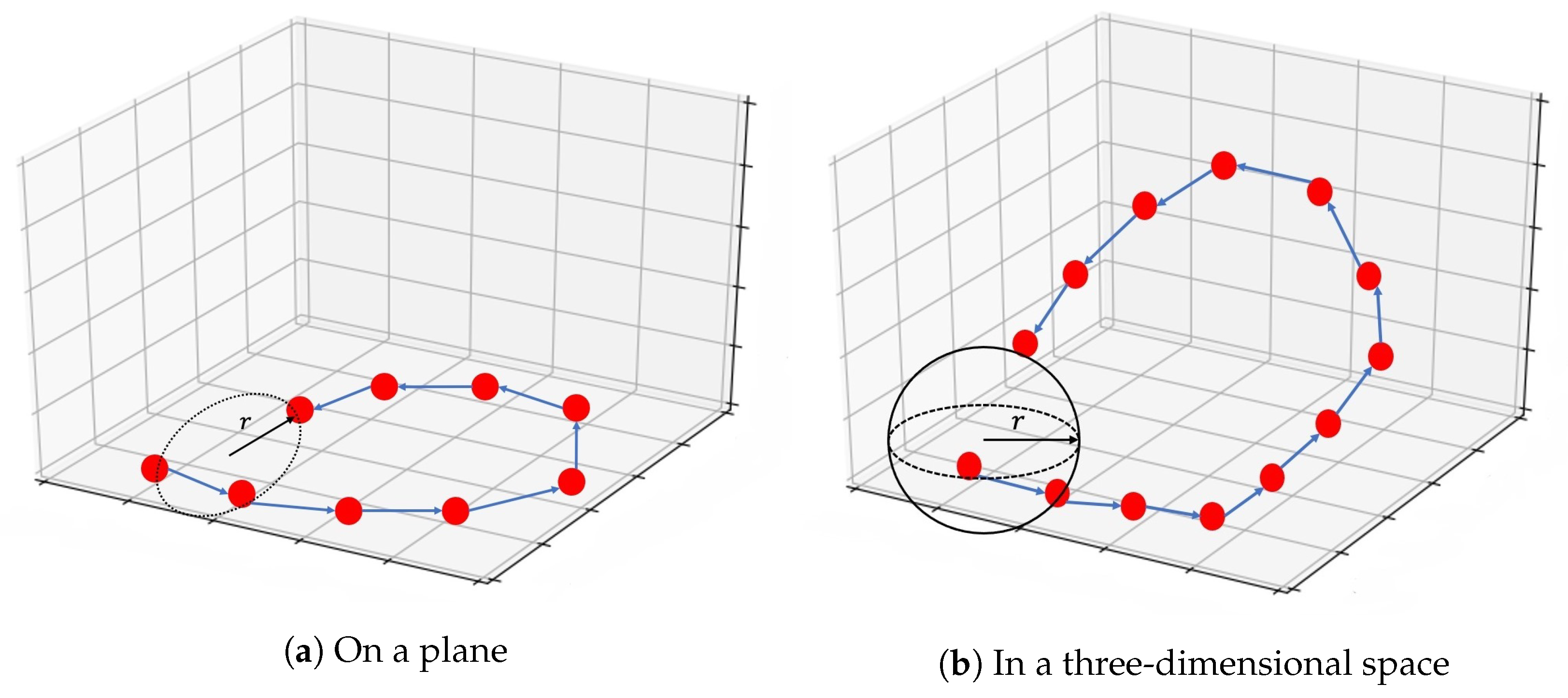
When a loop closure occurs, a portion of the sensor’s trajectory must be in close proximity to a ring structure. This means that if the sensor revisits a previous location, it must be moving in the opposite direction of some of its previous trajectory, as shown in
Figure 3. Leveraging this feature, we propose a method for coarse loop closure detection that incorporates IMU information. By using the acceleration and angular velocity of the IMU, we can determine the direction of movement of the robot. When the direction aligns with the positive direction of the IMU reference frame, the value is set to 1; otherwise, if the direction is opposite, the value is set to 0.
In this way, when a keyframe enters the loop closure detection thread, a change in the direction of motion along one axis indicates that the sensor may be moving in the opposite direction and a loop closure may occur. This is the rough detection method using IMU data. However, it is impractical to match all keyframes based on orientation requirements. To address this, we introduce a threshold radius
r to filter out keyframes that meet the orientation requirements. In [
25], a search radius of 10 meters was used for lidar SLAM, but this method is sensitive to point cloud density and depth accuracy. Thus, we set the threshold radius
r to 20 times the stereo baseline. This prevents the system from missing loops and reduces unnecessary keyframe matching. For 3D scenarios, such as drone flight as shown in
Figure 3b, the principle is similar to the 2D case. We simply expand the circle of radius
r into a sphere and search for possible matching keyframes within it. If there are other keyframes within the threshold, loop closure detection will begin. Features will be converted into bag-of-words vectors, and the DBoW2 database will be searched within the threshold radius. This method can significantly reduce unnecessary calculations and CPU usage as the number of keyframes increases. Furthermore, the longer the system runs, the more evident this advantage becomes.
3.3. Main Process
The tracking thread is responsible for feature extraction from sensor input and tracking them. Initially, the system relies on pure visual initialization, which uses stereo disparity to calculate the depth of feature points and backprojects them into the map. With the input of multi-sensor information, the inertial data are used to calculate the transformation between and the world reference as the initial value for nonlinear optimization instead of the constant velocity model. Then, map points observed in the previous frame are projected onto the current frame with . Finally, an optimization procedure is carried out to estimate the orientation and translation of the current frame. Once the pose has been estimated, the current frame is evaluated to determine whether it should be considered as a new keyframe in a similar strategy to ORB-SLAM3. In cases of rapid rotation or occlusion where feature points between frames cannot be matched, the pose is calculated by integrating the inertial data, and the system continues to track. If occlusion persists in the two incoming image frames, then the tracking fails and relocalization is performed using the DBoW2 bag-of-words model to increase the robustness of tracking.
The local mapping thread is responsible for performing BA optimization to refine the pose and 3D map points of keyframes in the map. Whenever a keyframe is inserted, it establishes a co-visible graph with a set of connected keyframes, calculates the depth through binocular disparity, back-projects the unmatched feature points into the world reference, and fuses redundant 3D feature points in the map. Other keyframes that observe the current keyframe points but are not connected are included in the optimization, but their poses remain fixed. Within 2 s of the system running, BA optimization is performed with the pure vision module using Equation (
18). Then, the IMU parameters are initialized and refined using the MAP estimation technique shown in Equation (
19). Finally, the vision–inertial pose graph is used to judge the quality of variable optimization and guide the system to choose a better nonlinear optimization method, preventing some parameters from being over-optimized.
The loop closing thread is responsible for correcting the accumulated drift, especially over long-term operations. When a new keyframe is inserted, the direction of movement of the current frame relative to the world reference is calculated using the IMU data and stored in a unit-bearing vector. The system then performs a coarse judgment of loop detection by searching in real-time for all keyframes within a radius
r and two opposite directions described in
Section 3.2. If the coarse judgment passes, the system starts the loop detection approach, and matches features between the current keyframe and other keyframes within the radius in a fine detection process. If the match is successful, the SE(3) transformation between the current frame and the matching keyframe is calculated, correcting the poses of keyframes in the co-visible graph, and the map points through pose propagation to correct the accumulated drift. After a loop correction, a full BA is executed in a new thread to further refine the map without affecting real-time performance.
4. Experimental Results
To demonstrate the performance of our system, we have conducted experiments using the EuRoC [
26] dataset. The datasets consist of recordings of aircraft flying in large industrial environments, which are divided into three modes based on illumination, speed, and texture: easy, medium, and hard. We conducted multiple experiments on each of the 11 sequences and compared our system with other state-of-the-art systems. The experiments were divided into three parts:
Section 4.1 is the simulation of single-session sequences,
Section 4.2 discusses the IMU and loop closure, and
Section 4.3 is a comparison of computing time. We aligned the estimated trajectory with ground-truth using SE(3) transformation in stereo-inertial sensor configurations. All experiments were performed on a machine running Ubuntu18.04 with an Intel Core i5-1135CPU, at 2.4 GHz, and 16 Gb memory, using only the CPU.
Histogram equalization is applied to each input image to enhance its contrast, which is highly significant for solving under- or over-exposed environments. FAST feature points are extracted from an 8-scale pyramid model with a scale factor of 1.2. Additionally, the system uses the quadtree algorithm to recursively search for groups of points and employs the point with the highest corresponding value of the FAST corner point in the neighborhood of local feature points for non-maximum suppression and fast screening. The descriptor is calculated using the BRIEF algorithm to enable the matching of feature points.
4.1. EuRoC Sequences
We select the most representative SLAM systems for each method. BASALT relies on optical flow and BA optimization. OKVIS is considered a pioneering work in the field of visual–inertial SLAM, based on nonlinear optimization. ORB-SLAM3 is considered the most advanced system currently available. KIMERA is an open-source SLAM library based on metric semantics. It consists of multiple modules and introduces semantic segmentation alongside SLAM. We use the Absolute Trajectory Error (ATE) to compare our system with other state-of-the-art SLAM systems, as shown in
Table 1. The data in the table are obtained from the corresponding papers, and some missing data are from our reproduction of their papers.
where
N represents the number of keyframes,
stands for the translation of the transformation,
represents the estimated trajectory, and
is the real trajectory.
It can be concluded that the ATE of the stereo-inertial system is slightly better than that of the monocular-inertial system, and has a lower dependence on scale optimization. At the beginning of the system, the stereo system only requires one frame to initialize, while the monocular system requires multiple inputs to triangulate. Additionally, for the calculation of the depth of feature points, the stereo-inertial system can choose between stereo triangulation or using the left (or right) camera from the previous frame to the current frame. These advantages are the reasons why the stereo system is more robust.
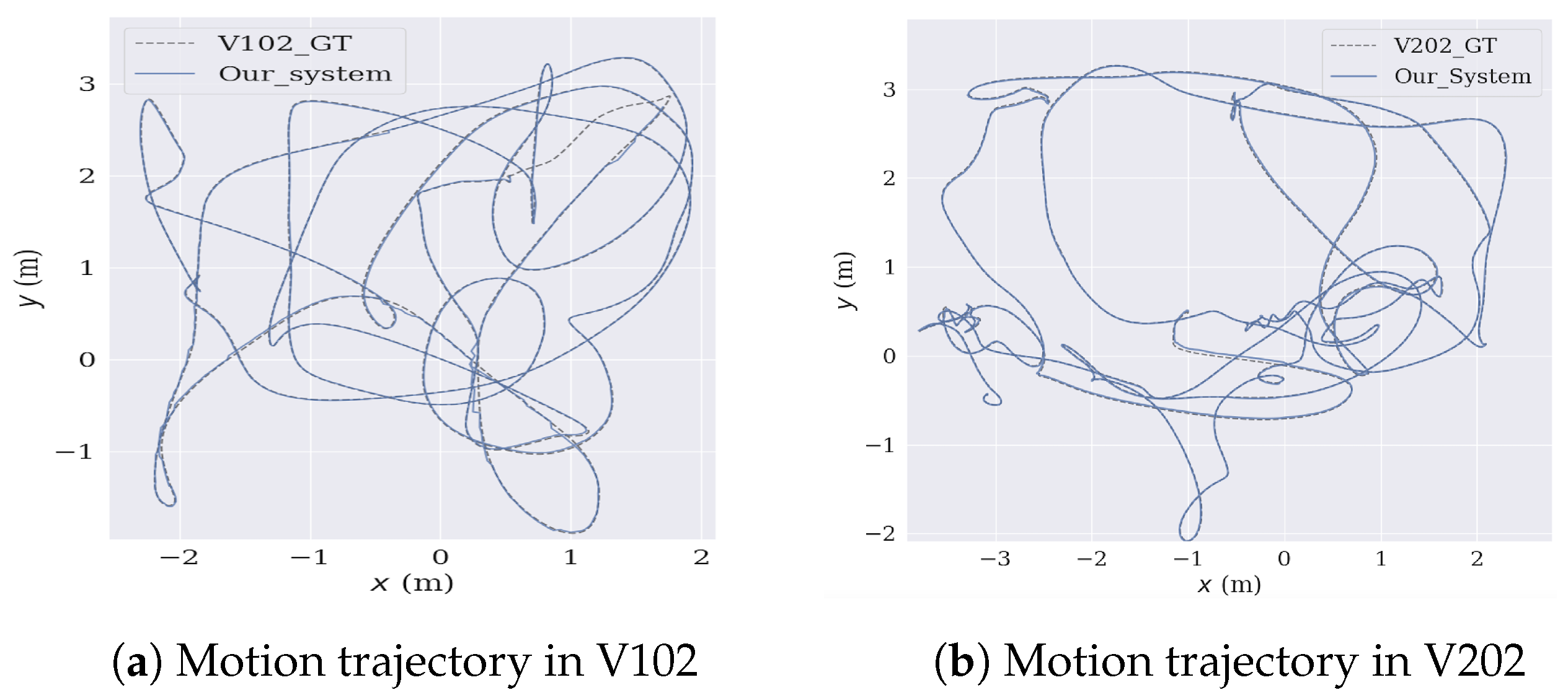
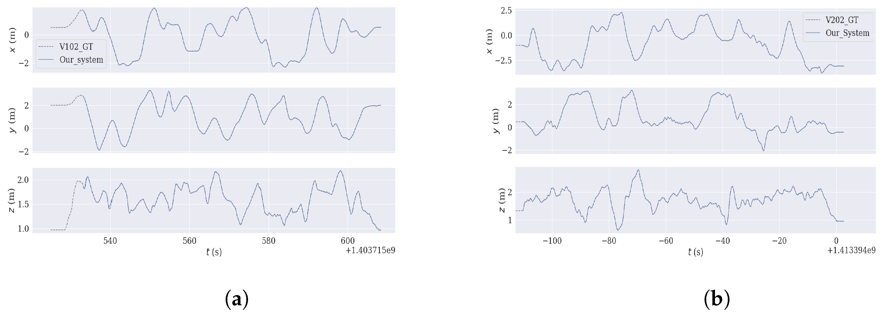
To summarize the system’s performance, we presented the median of ten executions for each sequence. KIMERA emphasizes SLAM with semantic segmentation, while VINS-Fusion utilizes keypoint extraction and optical flow for tracking. However, the rapid movement of unmanned aerial vehicles may result in blurriness. As a result, our system demonstrated significantly higher accuracy than VINS-Fusion and KIMERA in certain scenarios, highlighting the advantages of medium-term and long-term data association. Our system achieves comparable accuracy to BASALT and ORB-SLAM3, except in the case of the V203 sequence in EuRoC where BASALT fails due to missing frames and severe motion blur. In contrast to BASALT, which relies on optical flow and cannot track pixel intensity variations during motion blur, our tightly-coupled approach, combined with MAP estimation, allows for rapid IMU initialization and the utilization of optimized inertial variables, resulting in improved accuracy. The local mapping thread’s joint visual–inertial optimization further refines the solution, making the system more accurate and faster. Our coarse-to-fine optimization method’s advantage is the two cooperating threads that make the system more robust. Every time a loop is detected, a full BA is performed to optimize all camera poses in the map, ensuring the localization accuracy of the entire system. Our system achieved the highest accuracy in most of the Machine Hall (MH), V102, and V201 sequences. In complex flight scenarios, our system’s trajectory closely follows the ground truth from start to finish, as shown in
Figure 4, demonstrating our system’s advantages in short-term, medium-term, and long-term data association.
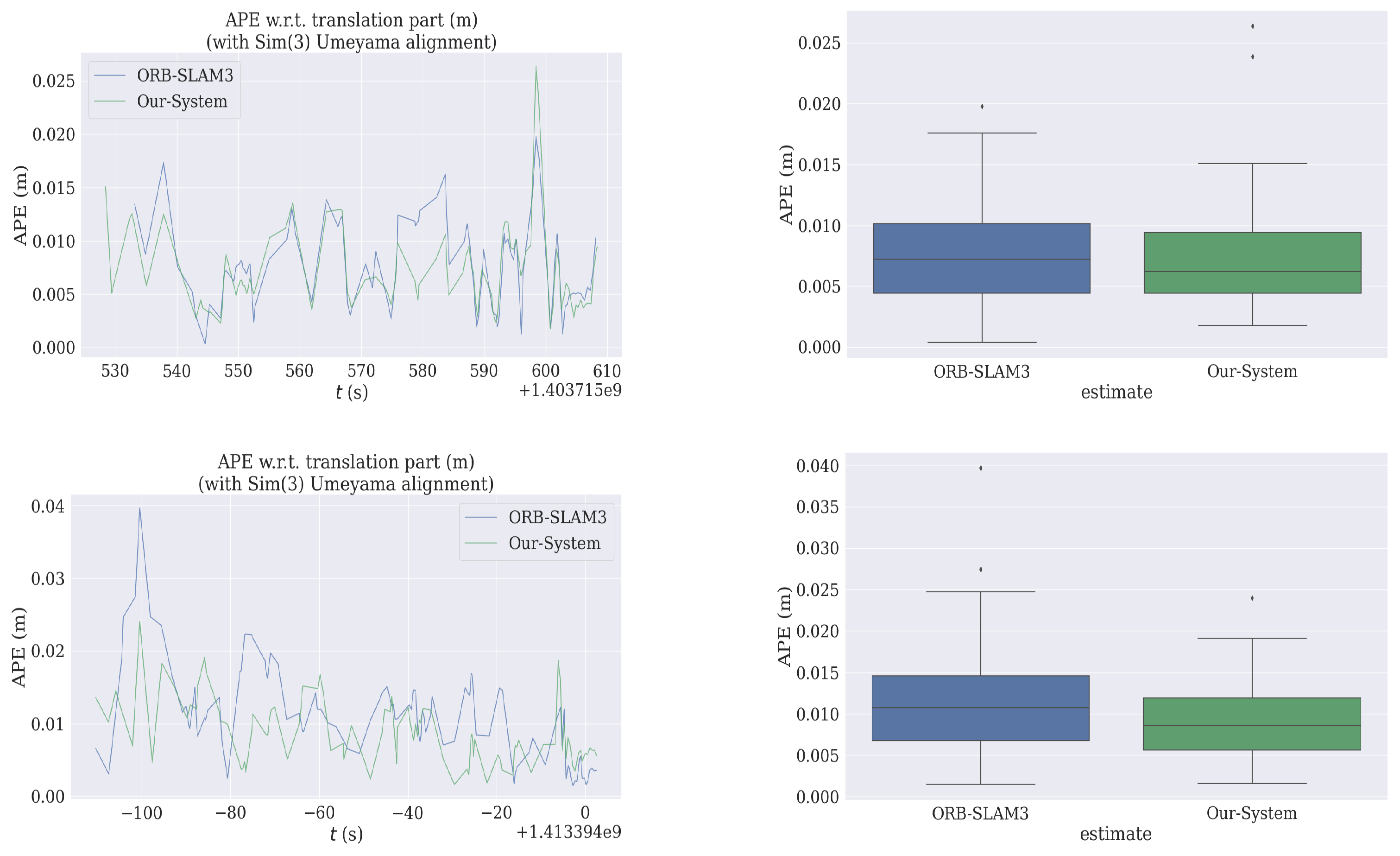
Figure 5 illustrates the tracking errors in the x, y, and z directions over time. As shown, the relative error of our system does not increase with distance, nor does the drift suffer from drifting in any of the three directions, remaining consistently low. This indicates that our system effectively suppresses noise. The tightly coupled approach and coarse-to-fine optimization we proposed, combining the characteristics of the tracking and local mapping threads, enable the system to run for extended periods without accumulating drift, achieving global consistency and building a reliable map. In
Figure 6, our system and ORB-SLAM3 show a similar trend in ATE error, with both systems remaining within a constant range over time. Our system exhibits slightly superior positioning accuracy, which aligns with our objective of proposing a lightweight solution while upholding high precision.
4.2. IMU and Loop Closure
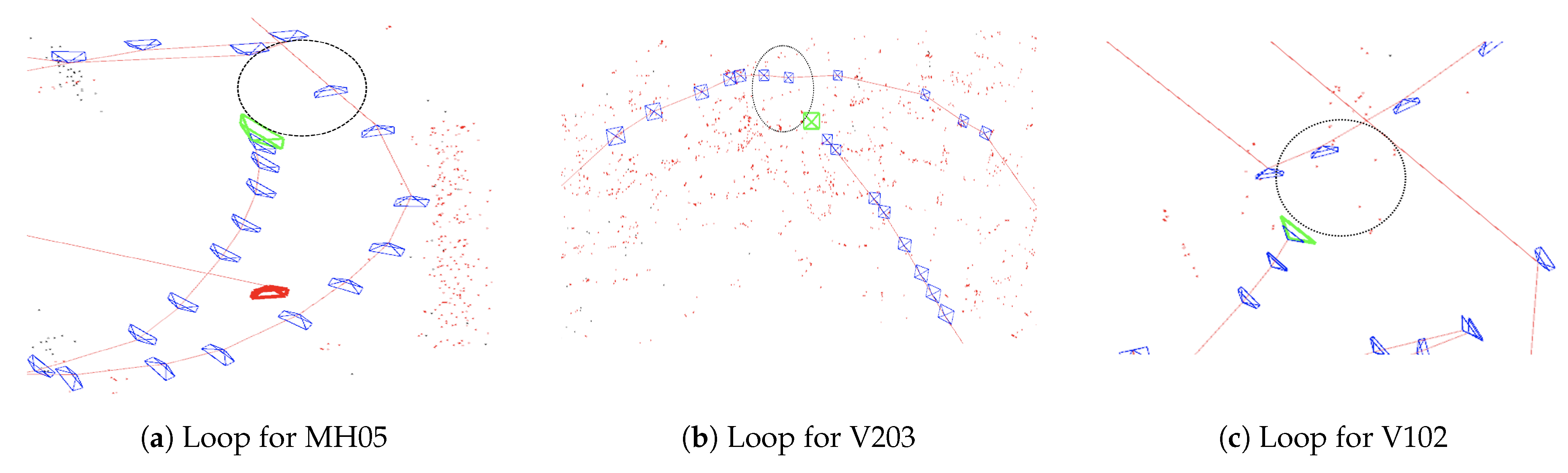
As shown in the partial map in
Figure 7, our loop closure detection method effectively identifies loop closures and forms a nearly closed trajectory shape each time a loop is detected. The use of IMU data to calculate the sensor’s displacement direction and a radius threshold of 20 times the stereo baseline from the current keyframe’s camera optical center are key factors in achieving accurate and reliable loop closure detection. Our system then utilizes the DBoW2 database to identify three consecutive keyframes with temporal consistency to ensure higher recall. Once a feature matching is successful, we project the feature points of the three co-visible keyframes into the matching frame and check if the number of feature points is sufficient to close the loop.
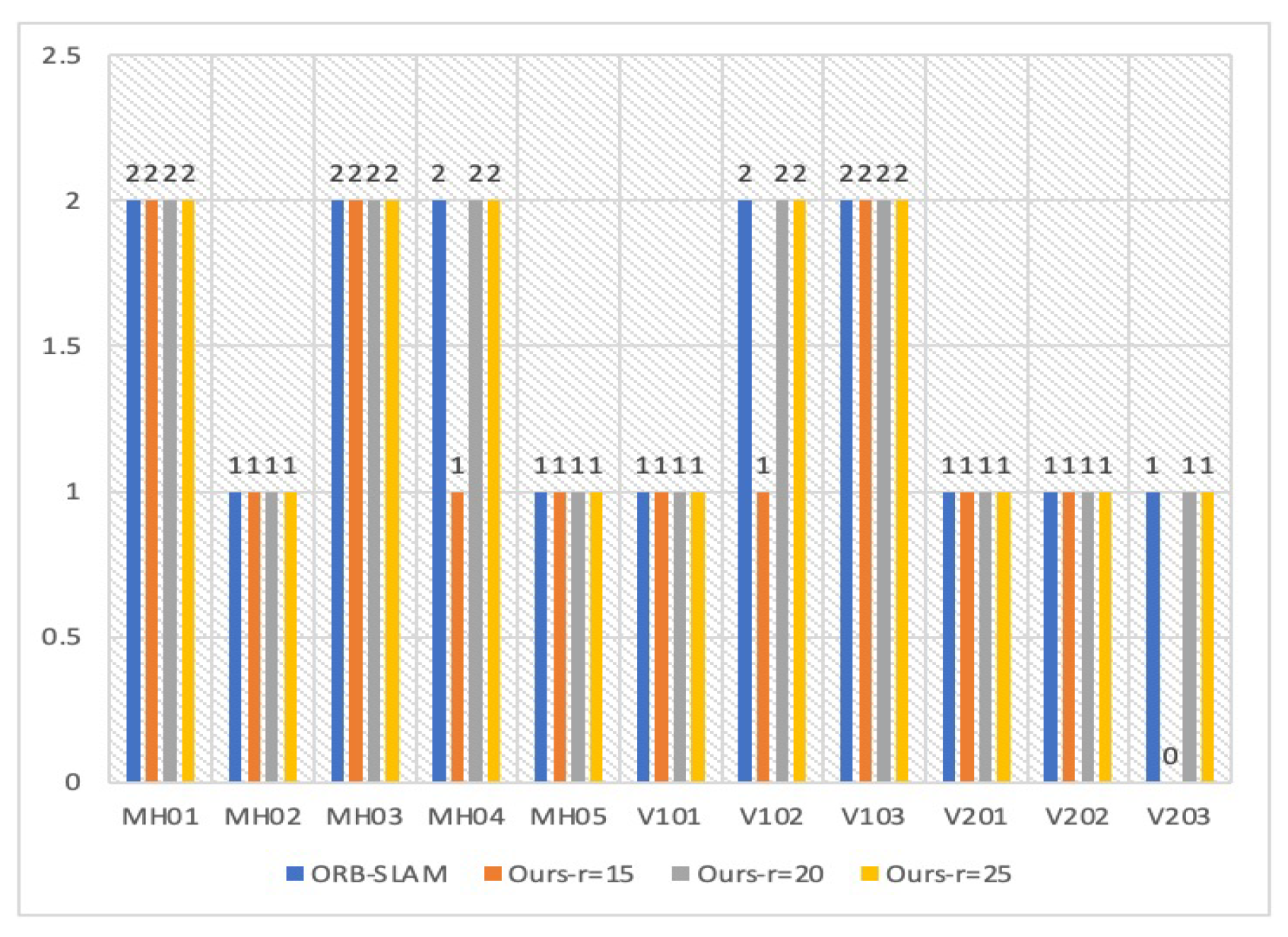
In order to filter out unnecessary keyframes and reduce computational costs, we use a radius
r to separate possible keyframes for loop detection, as shown in
Figure 7. However, it is important to ensure that this approach does not miss any loops. To evaluate the effect of different radii, we conducted experiments and plotted the results in
Figure 8. As SLAM is a probabilistic event, the mode was used as the evaluation criterion to reflect the effect of different radii on loop closure. We found that a radius of 20 times the stereo baseline was optimal for the EuRoC dataset, as it ensured both accuracy and reduced CPU utilization. A larger radius would be closer to the original DBoW2 calculation method, while a smaller radius would negatively impact loop detection. Overall, our approach strikes a good balance between accuracy and computational efficiency.
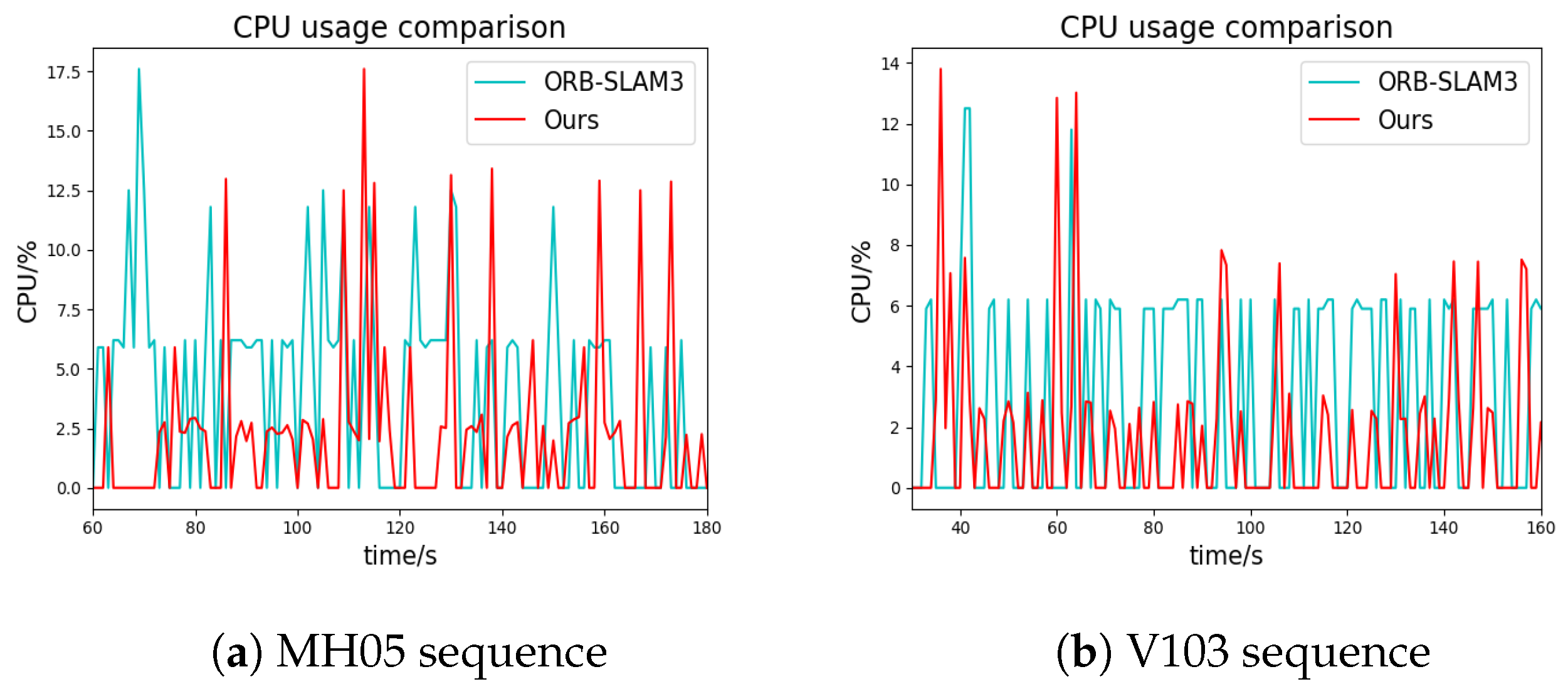
Compared to ORB-SLAM3, our system has clear advantages in terms of CPU load. In ORB-SLAM3, the loop detection is triggered every time a new keyframe is added, and the DBoW2 database is searched to check if the robot revisits a previous location. As shown in
Figure 9, the CPU usage of ORB-SLAM3 fluctuates regularly. When the matching between the current frame and the database is successful, the CPU needs to process the similar transformations between them and use graph optimization to approximate the optimal solution, resulting in the highest CPU usage. Our algorithm has a similar trend to ORB-SLAM3, but due to the coarse-to-fine optimization using IMU data, it is no longer necessary to search the DBoW2 database every time, leading to lower CPU usage.
Figure 9 demonstrates that ORB-SLAM3 and our system have the same number of peaks (once the loop merge occurs successfully, a new thread will be started, so that the CPU usage will reach its peak), which indicates that our system does not miss any loops despite using additional constraints. Not every successful coarse judgment will trigger a loop closure. Nevertheless, our system is already very friendly to some low-end processors compared to real-time loop detection.
4.3. Computing Time
Table 2 shows the running time of the main operations in the tracking and local mapping thread between the stereo-inertial ORB-SLAM3 and our system on V102 and V202. As for loop closure thread, this paper relies on the IMU data to analyze the motion trajectory of the camera, while ORB-SLAM3 performs place recognition on incoming keyframes every time, so it is not fair to compare the time of loop closure thread between them.
Compared to ORB-SLAM3, our system boasts a significant advantage by operating in real-time, processing up to 50 frames with around 8 keyframes per second. The system maintains a consistent range of time differences in operations such as feature extraction and stereo matching, ensuring a reliable and efficient performance. While ORB-SLAM3 employs a constant velocity motion model for feature point tracking, our system uses the optimized IMU variables to generate a more accurate initial value for the pose. This approach enables us to reduce the number of iterations required for pose optimization, resulting in a higher frame rate.
Our local mapping thread incorporates three graph optimization techniques: inertial-only, vision-only, and vision–inertial. However, we have an additional variable state observer that selects the appropriate graph optimization method based on the joint visual–inertial error. This ensures that certain variables are not over-optimized and enhances the accuracy of the system.
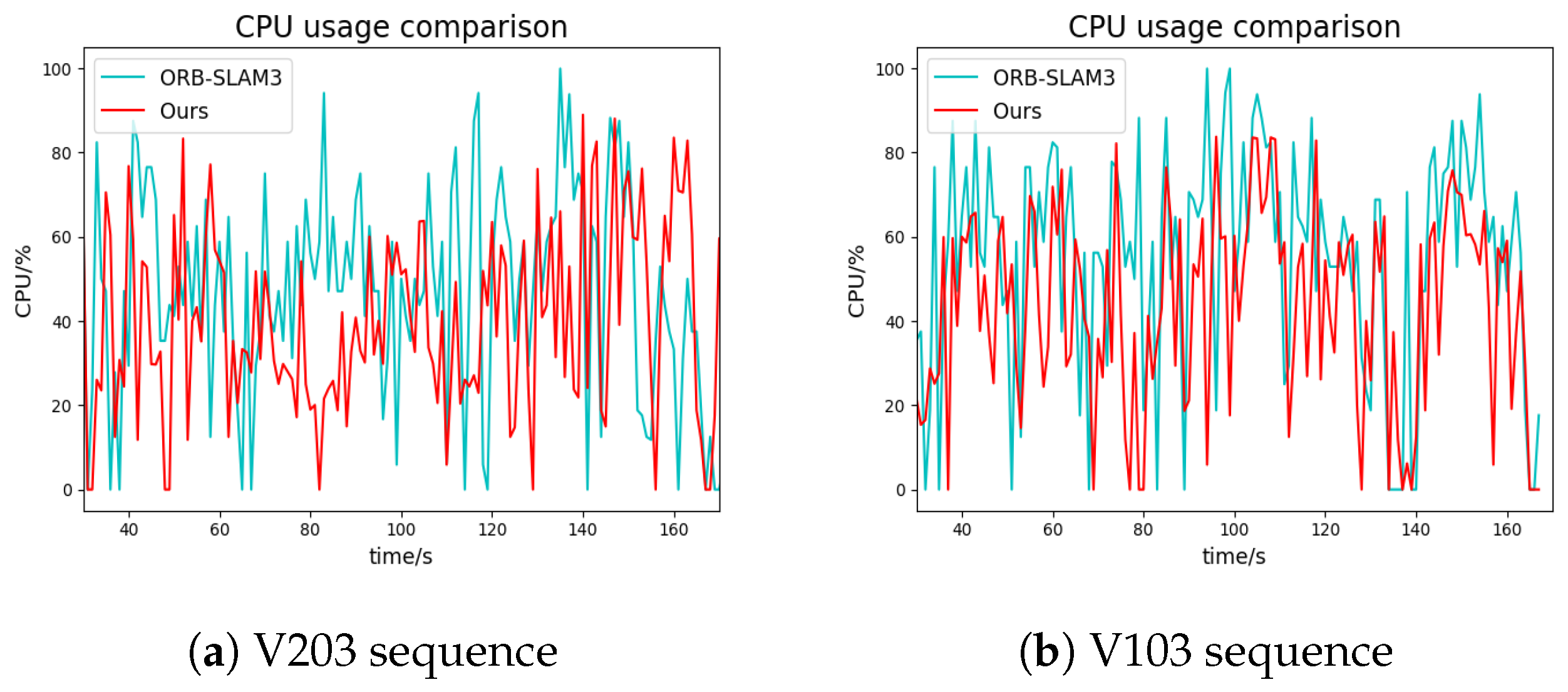
Furthermore, we compared the CPU load of our system with that of ORB-SLAM3 in the local mapping thread. The results demonstrated the effectiveness of our visual–inertial pose graph as an observer in reducing CPU load, as depicted in
Figure 10. Overall, our system presents a significant improvement over ORB-SLAM3, achieving real-time operation and offering notable advantages in accuracy and efficiency.
5. Conclusions
In this paper, we present a lightweight stereo-inertial SLAM system that employs nonlinear optimization and feature-based techniques while leveraging IMU information throughout the pipeline. To optimize the inertial bias and noise efficiently, we propose a coarse-to-fine variable optimization method that enables the use of IMU data for tracking from the outset, thus reducing the number of BA iterations. Moreover, we incorporate optimized inertial data as a temporary replacement for feature point tracking in challenging scenarios such as fast rotation, occlusion, or poor texture, thereby enhancing the system’s robustness. In the local mapping thread, we enhance the solution through joint visual–inertial optimization. We propose a novel visual–inertial pose graph that effectively identifies the variables requiring optimization, preventing continuous over-optimization of IMU parameters and reducing CPU load. In the loop closure thread, we integrate inertial data and sensor motion information as a prerequisite for loop detection. Additionally, we introduce a threshold radius to selectively filter out keyframes that satisfy the orientation requirements. This ensures that the system avoids missing potential loops and reduces the frequency of unnecessary DBoW2 database retrieval, thereby further alleviating CPU pressure on the system. Experimental results demonstrate that our system achieves improved accuracy with low CPU consumption and enhanced robustness compared to other state-of-the-art approaches on benchmark datasets.
However, our system has higher requirements for IMU data as they are utilized for initializing the pose between consecutive frames. Additionally, the selection of the threshold value for keyframe filtering is fixed, limiting its generalization to other cameras or datasets. Our future research direction will focus on setting the threshold as an adaptive value to accommodate a wider range of scenarios.


