Article

Decentralized Multi-UAV Cooperative Exploration Using Dynamic Centroid-Based Area Partition

1
Defense Innovation Institute, Chinese Academy of Military Science, Beijing 100071, China
2
Intelligent Game and Decision Laboratory, Beijing 100071, China
*
Author to whom correspondence should be addressed.
These authors contributed equally to this work.
Drones 2023, 7(6), 337; https://doi.org/10.3390/drones7060337
Submission received: 5 April 2023 / Revised: 10 May 2023 / Accepted: 20 May 2023 / Published: 23 May 2023
(This article belongs to the Special Issue Multi-UAV Networks)

Abstract

:
Efficient exploration is a critical issue in swarm UAVs with substantial research interest due to its applications in search and rescue missions. In this study, we propose a cooperative exploration approach that uses multiple unmanned aerial vehicles (UAVs). Our approach allows UAVs to explore separate areas dynamically, resulting in increased efficiency and decreased redundancy. We use a novel dynamic centroid-based method to partition the 3D working area for each UAV, with each UAV generating new targets in its partitioned area only using the onboard computational resource. To ensure the cooperation and exploration of the unknown, we use a next-best-view (NBV) method based on rapidly-exploring random tree (RRT), which generates a tree in the partitioned area until a threshold is reached. We compare this approach with three classical methods using Gazebo simulation, including a Voronoi-based area partition method, a coordination method for reducing scanning repetition between UAVs, and a greedy method that works according to its exploration planner without any interaction. We also conduct practical experiments to verify the effectiveness of our proposed method.

1. Introduction

Using swarm unmanned aerial vehicles (UAVs) to execute collaborative missions in local areas has become an important direction of development in unmanned system applications in recent years. Small UAVs are characterized by their ease of deployment and agility [1], but the problem of collaborative control has always been challenging, especially in search and rescue missions [2,3] where the environment structure may change and the UAV swarm may not have prior knowledge of the task area. This requires the ability of autonomy to be able to avoid obstacles and accurately reach the task area, as well as the ability of intelligence to build environment maps and even identify specific targets [4,5,6].
In this study, we consider using a UAV swarm for exploring unknown areas and dispatching multiple UAVs to collaboratively map specific areas, in order to achieve rapid area reconnaissance. Therefore, we hope that the system can run efficiently and handle the problem of perception overlap or motion interference between UAVs [7,8,9,10]. Each participating individual can maintain a relative balance in task partitioning appropriately and dynamically. At the same time, the system needs to have a certain degree of robustness so that the task can be completed even if some individuals in the swarm are damaged [11].
Based on the above considerations, we propose a decentralized collaborative exploration method in this paper. The key of our method is a novel dynamic centroid-based partition algorithm, allowing the work area of each UAV to be dynamically adjusted as the mission progresses. The framework structure of the entire system is shown in Figure 1. Each UAV independently runs localization, mapping, partitioning, and planning, with only a small amount of pose and weight parameters shared among the network. After the initial partitioning is generated, to ensure independence in their work, each individual UAV prioritizes finding unexplored target directions in their own area. Within the partitioning calculation, based on the receding horizon next-best-view (NBV) exploration planner [12], our proposed method generates rapidly-exploring random tree (RRT) [13] with a constrained range, and the task can be quantitatively represented. By composing the information of the UAV swarm’s pose and task weight, we adopt the concept of centroid, whose variation results from changes in area partitioning, ensuring flexibility in mutual work. In the mapping module, Octomap [14] is used to provide a quantitative expression as free, occupied, and unknown for exploration.
The main contributions of this paper are as follows:
  • We propose a dynamic centroid-based area partition method that takes into account both the positions and current tasks of each UAV during the exploration process. This approach ensures that the UAVs that detect fewer tasks are allocated more mission area in the next step, maximizing the efficiency of the exploration process.
  • The NBV exploration planner has been improved by making modifications so that it only samples within a dynamically partitioned area. Additionally, we have innovatively formulated a weight to describe task quantity for the purpose of more effective partitioning.
  • The performance of the proposed method is validated by comparing with three classic multi-UAV cooperative exploration methods in both indoor and outdoor simulation environments. The practical experiment is also conducted to verify its feasibility.
The remainder of this paper is organized as follows. In Section 2, the works related to swarm UAVs’ cooperative exploration and mapping are reviewed. Section 4 is devoted to describing the details of our method, and in Section 5, comparative experiments in simulation environments are given. The results of practical experiments are discussed in Section 6. Finally, Section 7 concludes this paper and points out potential future improvements.

2. Related Work

In recent years, significant progress has been made within the academic community regarding collaborative exploration by multiple UAVs in unknown environments [15]. In light of our research focus, this paper will examine three areas related to collaborative exploration: methods for multi-UAV coordination, multi-UAV mapping, and exploration in unknown environments.

2.1. Multi-UAV Coordination for Exploration

Using multiple UAVs to increase exploration efficiency is a common practice, and related issues have been extensively studied [16]. One classic method involves maximizing overall utility while minimizing the potential overlap of measurements among UAVs [8]. This idea has been employed in many works such as [10,11,17]. However, as the number of UAVs increases, uncertainty [18] and redundant scanning between them become more prevalent, especially in larger environments where the sensor range is relatively small compared to the scale of the environment.
In conventional multi-agent allocation problems, a TSP-greedy allocation (TSGA) planner with ideal centralized architecture and communication assumptions is utilized to optimize global utility [19]. This approach considers the whole global task, which may be time-consuming for collecting tasks in the center. Alternatively, a dynamic Voronoi partition has been utilized in [7,10] to assign different target locations to individual UAVs, guaranteeing the separateness between them. However, this area partition-based method may not always be optimal as it does not consider the exploring process of each UAV, resulting in less efficient task allocation.
Therefore, in this paper, a dynamic centroid-based area partition is proposed, which considers the exploration process of each UAV for more reasonable task allocation. When a UAV has an insufficient number of candidates, it will be assigned a larger partitioned area to explore. The partition is processed dynamically to adapt to changing situations.

2.2. Multi-UAV Mapping for Exploration

To perform target selection and quantitative calculation in planning, it is necessary to have a map that depicts the environment and further exploration areas. Two representative volumetric mapping methods used in UAV exploration are truncated signed distance field (TSDF) [20] and occupancy [14]. When employing multi-UAV mapping methods, the key issue is often the map merging [21]. Previous works such as [8,17] involve each UAV maintaining its local map and correcting odometry errors while exploring. They then transmit their local maps with uncertain information to a central work station who can combine local maps into a global one for further optimization. In [22], sensor messages are shared among UAVs, and Gaussian mixture models (GMMs) are adopted to assist the exploration planner of each UAV. In [11], two maps are utilized: a low-resolution map for navigation and a high-resolution map for reconstruction. In order to achieve efficient coordination in a decentralized method, it is crucial to share the global map message among UAVs as quickly as possible. This is one of the central issues that we address in this paper.

2.3. Exploration in Unknown Environments

While fully functional UAVs possess autonomous sensing and computing capabilities, the exploration planner enables them to independently perform tasks in unknown environments. Existing works fall into two categories when executing under unknown: frontier-based methods [23,24,25] and sampling-based methods [11,13,26,27]. With given frontier clusters [28] or sampled viewpoints [27], an information-theoretic measure is optimized to calculate information gain, resulting in reduced map uncertainty. The frontier-based method explicitly computes the boundary between the known and unknown areas and assigns UAVs to frontiers iteratively, but the frontier selection process can be time-consuming as it traverses all surface voxels in a large environment [23]. Some methods reject unsuitable frontiers during selection [1] to ease the computational burden. On the other hand, the sampling-based method randomly selects viewpoints in free areas, such as the rapidly-exploring random tree (RRT) [13] and probabilistic roadmap planner (PRM) [3], which deliver speed and probabilistic completeness. However, these two methods could converge locally.
The two mentioned categories were widely used in the exploration planning of a single UAV. However, for multi-UAV exploration, a coordination module is required to prevent collisions and redundancies. The NBV method [12] is commonly utilized in such scenarios. This method iteratively selects viewpoints in free space to refresh candidates’ paths, ensuring a consistent update rate. Our proposed method follows this approach by integrating the strengths of the sampling-based method. This enables frequent recollection of viewpoints to avoid collisions and facilitate flexible collaboration between UAVs.

3. Problem Statement

The task of multi-UAV exploration in an unknown environment performs the process of exploring and mapping iteratively. A 3D workspace WS of known size is given before the task for establishing the concerned area; all UAVs will explore the workspace. Exploration processing by a UAV team contains N identical UAV with four degrees of freedom, as the 3D position [ x , y , z ] T R 3 and the yaw angle ψ S 1 . The UAV state can be described as x = [ x , y , z , ψ ] T . In each platform, a depth camera is equipped to collect the environment information with a certain field of view.
The environment is reconstructed by an Octomap M , and the occupancy probability of each gird m M is initialized as P ( m ) = 0.5 . The posterior occupancy probability P m x 1 : t , z 1 : t is updated by the depth measurement z 1 : t and the UAV state x 1 : t from initial time to current time t. The grids in the map will be gradually scanned by the sensor and identified as either free grids M f = { m P m x 1 : t , z 1 : t < P f r e e , m M } or occupied grids M o = { m P m x 1 : t , z 1 : t > P o c c , m M } . P f and P o are given thresholds. Given a map M at time t, the receding horizon exploration planner decides an optimal path T * in every period. To seek the T * for the UAV so that it gathers measurements that reduce unknown space and maintain coordination, a cost function is formulated to measure the value of the candidate path, considering the uncertainty of the map M , the UAV team information R T , the location of waypoints in path T , and the time cost of the path c ( T ) .
T * = arg m a x T f ( M , R T , T , c ( T ) ) .
UAVs visit unknown spaces independently according to the outputs of the exploration planner. We assume that the UAVs are equipped with an accurate localization system. From the initial state, the UAVs are deployed and set with a connected network and a known relative position as in a practical task application.

4. Method

This paper describes the implementation of a decentralized structure, as illustrated in Figure 1. Each platform performs RRT-based planning, area partitioning, and mapping independently. The core parts of our proposed modules are as follows.

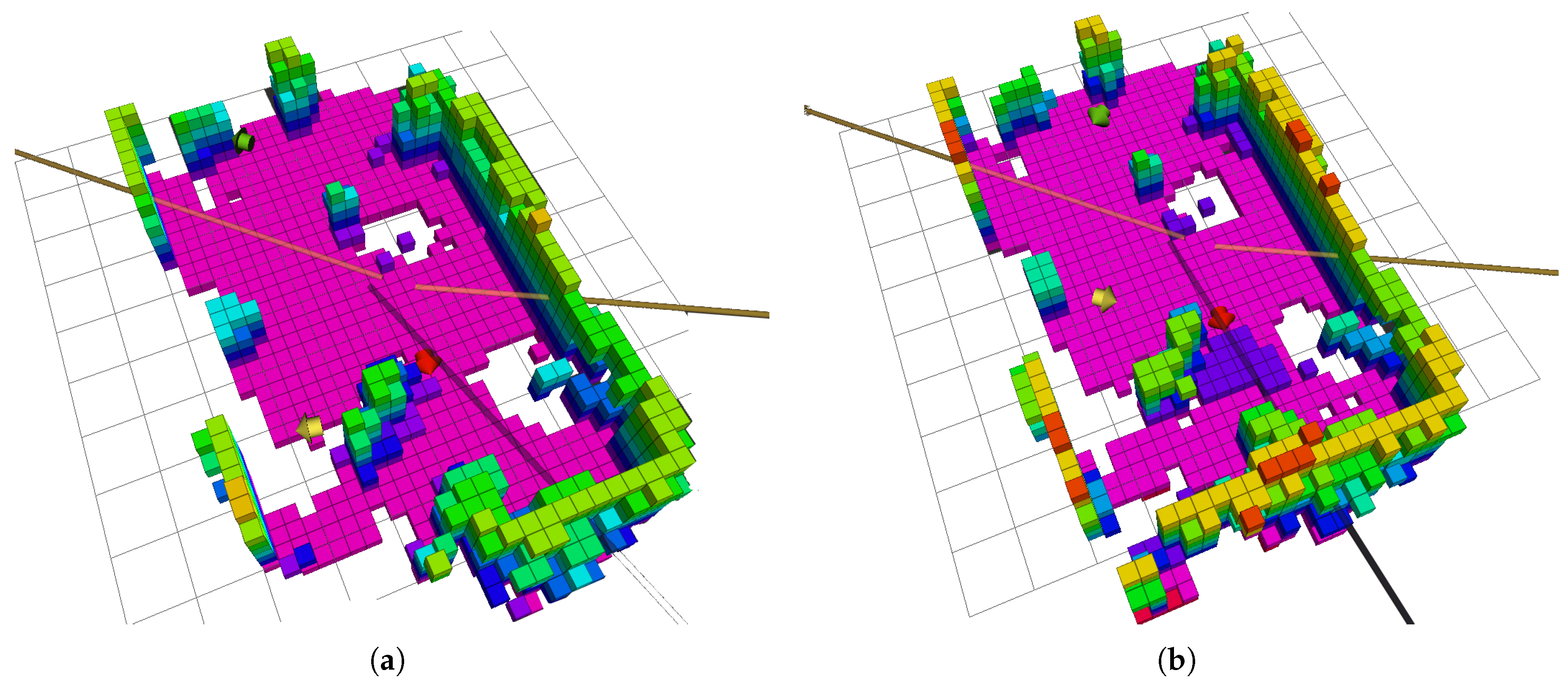
4.1. Dynamic Centroid-Based Area Partition

The area for each available UAV is partitioned using a dynamic centroid-based method, and each UAV is only responsible for its own refined area. Assuming that all of the UAVs work with the same efficiency using the same exploring planner on the same platform, a supposed idea is allocating UAVs equal assignments to prevent any UAV falls idle prematurely. However, it is not easy to count the tasks of all individual UAVs and re-allocate them in a decentralized structure.
To quantify the assignments of each UAV, we introduce the number of effective candidate nodes per unit space. The candidate nodes are generated by an RRT-based planner described in Section 4.3. In the area partition method, the candidate viewpoints are randomly sampled in the whole given workspace WS , and nodes are generated when viewpoints are placed in a given partitioned area PA . When effective candidate nodes N e , which can lead to environmental observation and the space volume V PA E , of the executable area are known, the weight w can be calculated as:
w = N e / V PA E .
The executable space volume V PA E in the PA can be approximated as Equation (3). The  V PA E represents the volume of a space, which is free, and the RRT-based planner in Section 4.3 can build a tree there.
V PA E V WS / C l o o p N T = V WS × N T / C l o o p .
The number of node sampling loops C l o o p is counted to calculate the size of the executable exploration area. With the executable space bigger, the  C l o o p is smaller because it is more likely to generate a candidate in PA successfully. An average number of samples required to generate a node can be formulated by N T / C l o o p .
The proposed dynamic centroid-based area partition calculates a virtual centroid X c = ( x c , y c ) adjusted from the information of platform weights w i for UAV i and its positions X i = ( x , y ) for the 2D projection from the poses, expressed in Equation (4). UAVs explore 3D space and map a 3D Octomap, while the two-dimensional coordinates of UAVs for partitioning the 3D area are considered to be the simplest form of calculation.
X c = i = 1 N w i · X i i = 1 N w i .
As illustrated in Figure 2 and depicted in Equations (5) and (6), the partition ray P r s for the area partition are generated according to the included angle between the j th and ( j + 1 ) th UAV when starting from the virtual centroid. θ P r j is the angle from x axis to P r j in a counterclockwise direction.
P r j ( T ) = X c + ( cos θ P r j , sin θ P r j ) T , T 0 ,
θ P r j 1 / θ P r j 2 w j + 1 / w j .
For UAV j , its exploring space PA j is bounded by two vertical planes P j and P j 1 , which are defined by partition rays and the axis of the centroid, see Equation (7). As illustrated in Figure 2, the pink area in the sector space marks the two-dimensional plane projection of the exploration space allocated ahead. The partition area is formulated by Equation (8). After the coordinates of the three-dimensional point under the x and y axes are converted to the polar coordinate system, the angle should be between θ P r j 1 and θ P r j .
P j = p cos θ P r j + π 2 , sin θ P r j + π 2 , 0 · p = 0 ,
PA j = { ( x , y , z ) x = ρ cos θ , y = ρ sin θ , z R , ρ R + , θ P r j 1 < θ < θ P r j } .
The core computing of the area partition is carried out on every UAV, and the platform weights and positions are shared between UAVs in real-time. With the change of them, every platform can adjust the working PA dynamically. The UAV with more detected tasks in the same volume space will attain more weight, the virtual centroid and the dividing planes will tend to be closer to it, and its PA in the next iteration will shrink. This tactic ensures the area assignment is in a relatively balanced condition, thus making the whole exploration more efficient.

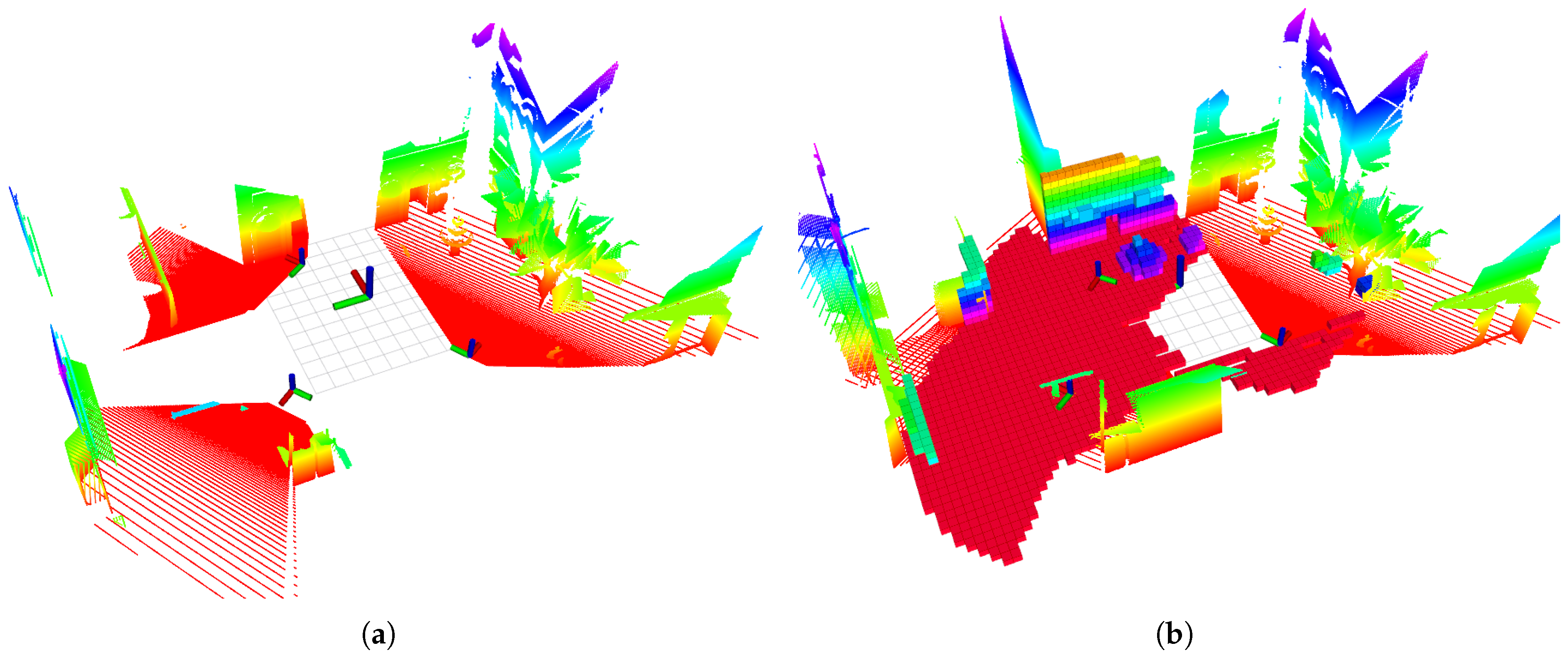
4.2. Distributed Ray-Cast Mapping

A numerically environmental expression is necessary for cooperative exploring. In a unified space, a shared environment could be divided into the unknown, occupied, or free parts. Due to its simple and fast searching character, the OctoMap is adopted in our method. Within it, the unknown, occupied, or free space can be represented by the cubic volume (voxel) in an octree.
In our decentralized setup, all recent sensor outputs, including poses, are shared among the UAVs, as depicted in Figure 1. The use of 5G WiFi ensures high-quality information sharing. We assume that the initial relative position is known, and a perfect localization node runs on each UAV to provide accurate real-time position data. By using the known initial relative position, the poses can be transformed into a unified coordinate system. Consequently, each UAV maintains its own global map with a unified coordinate system to enable cooperative planning, as illustrated in Figure 3. Collecting and aligning information within the team as much as possible promotes collaboration. In this mode, each UAV can consider the most comprehensive global information available.

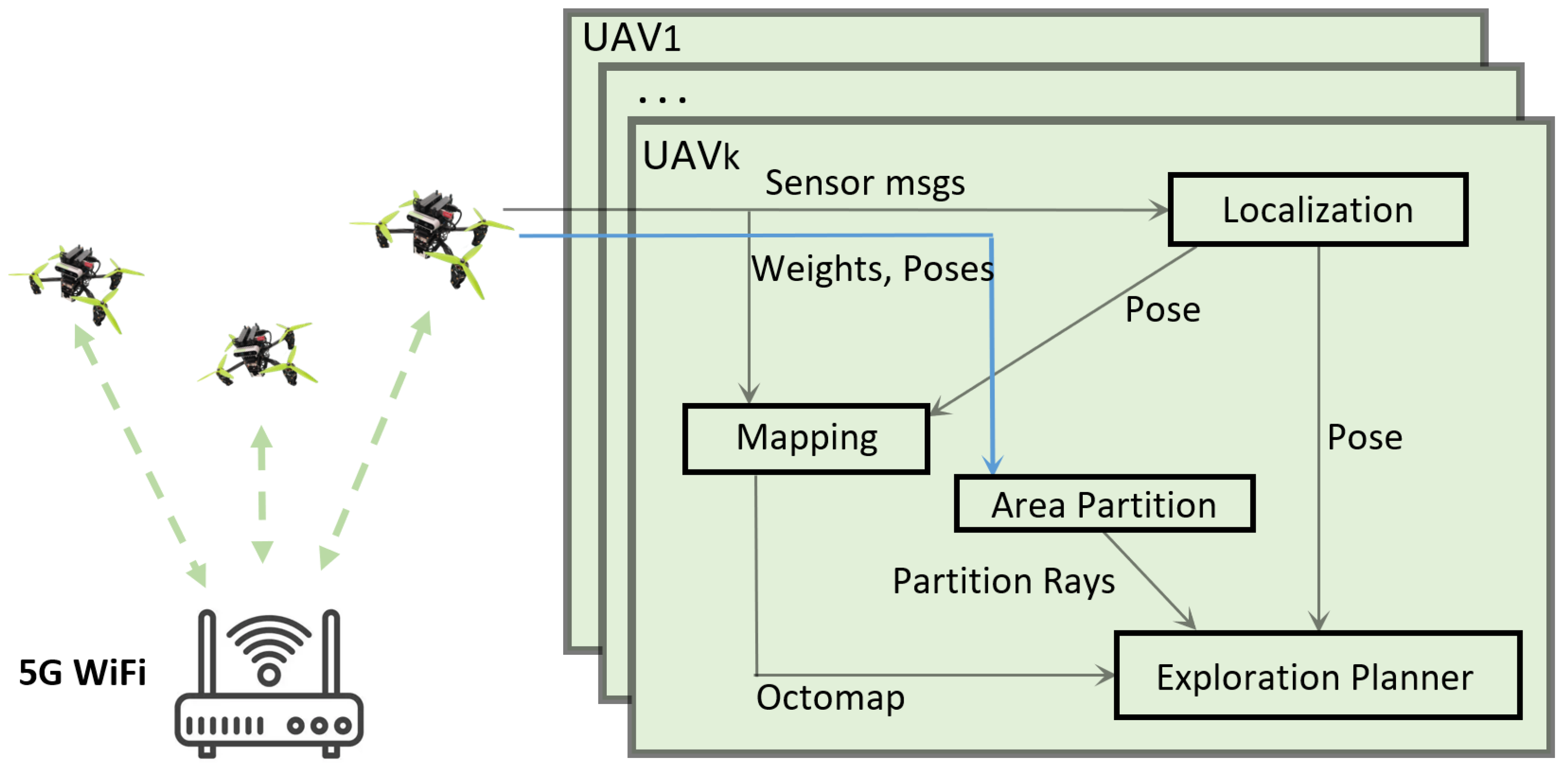
4.3. Decentralized Cooperative Exploration Planner

The approach presented in this paper constitutes an enhancement of a receding horizon NBV planner [12]. The planner is based on a sampling strategy that leverages RRT to generate plausible target points and feasible trajectories in free space. Each UAV runs the same planner, leveraging the same hardware and algorithms. The planning process is formalized in Algorithm 1. The RRT algorithm iteratively generates random points throughout the workspace, stopping when a point is placed within the PA of the corresponding UAV.
Algorithm 1 Decentralized Cooperative Exploration Planner
  1:
for Exploration is not over do
  2:
   Obtain the latest weights and poses of all UAVs
  3:
   Do the area partition
  4:
   Initialize the RRT T
  5:
   Initialize the N e = 0 , C l o o p = 0 .
  6:
   for  N T < N i n i t o r G ( n b e s t ) = 0  do
  7:
     if  N T < N t h r e s h o l d  then
  8:
        while True do
  9:
            C l o o p = C l o o p + 1 .
10:
           generate candidate C X U n i f o r m ( WS )
11:
            if  C is in PA  then
12:
                generate node n Connect ( C , T )
13:
                if  G ( n ) ! = 0  then
14:
                     N e = N e + 1
15:
                end if
16:
                break
17:
            end if
18:
     else
19:
        generate candidate C X U n i f o r m ( WS )
20:
        generate node n Connect ( C , T )
21:
     end if
22:
     if  N T > N M A X  then
23:
        Exploration is over and break
24:
     end if
25:
     Update n b e s t and B e s t B r a n c h
26:
   end for
27:
   update weight w = N e × C l o o p / N T
28:
   Share the latest weight in the team
29:
   Execute the planned path
30:
end for
Throughout the process, the planner generates a tree T consisting of nodes in the free space of an OctoMap M . Each node n corresponds to a potential viewpoint, with its state denoted by ξ = ( x , y , z , ψ ) T , reflecting position and yaw. The tree is constrained to remain in the collision-free space to guarantee safe planning. For UAVj, the best node n b e s t j is selected based on Equation (9), which considers the feasibility of the path. The function G ( n ) reflects the gain of the parent node, and a novel information value (with related parameters) can be expressed as g ( M , n , P j , P j 1 ) in Equation (10). This optimization aims to minimize Equation (1) considering M for information measurements and path planning, nodes corresponding to the path, and P j , P j 1 aggregating team information to enable coordination.
n b e s t j = arg m a x n T j G ( n ) ,
G ( n ) = G ( n p a r e n t ) + g ( M , n , P j , P j 1 ) ,
and
g ( M , n , P j , P j 1 ) = v F O V ( ξ ) M V ( v ) × e λ c ( σ ) f .
In this context, the function V ( v ) takes a value of 1 if the voxel v is unexplored, and 0 otherwise. Our objective is to explore the unknown space, and the visible voxels within the field of view of the sensor are accumulated to form a basic visibility score. The cost of a path from the initial node n 0 to n is determined by the RRT algorithm and denoted by c ( σ ) . To enable collaboration among the UAVs, the product function f is utilized, as shown in Figure 4. Each plane P exerts a repulsive factor of f = 1 + 1 / d , where d is the distance between the candidate node and the plane P . The term e λ c ( σ ) causes the visibility score to decrease smoothly as the path cost increases, while e 1 + 1 / d drives the UAVs away from the P j and P j 1 .
The algorithm initializes the value of n 0 in tree T as the current state of the UAV during the first initialization. Otherwise, the initial tree would be set as the previous best branch. The B e s t B r a n c h is defined as the branch from n 0 to n b e s t . To ensure that sufficient environmental information is obtained while generating nodes, the tree T must have a minimum of N i n i t nodes, and loops continue until a valuable solution is obtained with G ( n b e s t ) = 0 . To prevent the UAV from idling due to unreasonable area partitioning, the partition constraint is disabled when the number of tree nodes N T exceeds a certain threshold N t h r e s h o l d . Once N T > N M A X , the exploration is deemed to be completed. In each iteration, the first segment of the B e s t B r a n c h is considered the planned path. The weight w can be updated using Equation (12) according to Equation (2). Since WS is assumed to be given and V WS is constant and known, it is omitted.
w = N e / V PA E N e × S a m p l e l o o p / V WS × N T .
The algorithm presented in this paper is intended to be executed on each UAV independently. The planner and the area partition calculation are interdependent, and a smaller partition area can make it more difficult for the planner to generate an effective trajectory, resulting in a smaller weight. In turn, a smaller weight can lead to a larger partition being provided to the UAV during the partition area calculation.

5. Evaluation in Simulation

To demonstrate the superiority of the proposed method, we compared it with three representative algorithms. The first was the greedy method for group application, which did not employ cooperative settings (referred to as “greedy” in this context). The second [11] was the classic method that discounted the information gain based on the repeating area (referred to as “coordination” in this context). In this method, the gain was reduced based on the area within the sensor range of the current best nodes of other UAVs. The third method [7] used dynamic Voronoi partitions to assign different target locations to individual UAVs, minimizing duplicated exploration areas (referred to as “Voronoi” in this context). All of the three algorithms were decentralized and used RRT to generate candidate points.
Simulation experiments were conducted using Gazebo. All of the methods were tested with the same virtual UAVs and environmental settings. Each UAV was equipped with a depth camera that had a field of view [ 60 , 90 ] in the vertical and horizontal directions. For the indoor scenario, the camera was mounted with a downward pitch angle of 15 . For the outdoor scenario, it was mounted with a pitch angle of 35 . For all of the simulation experiments, the maximum velocity was set as ψ ˙ max = 0.5 rad / s and v max = 0.25 m / s , while the size of the collision detection box was assumed to be 0.5 × 0.5 × 0.3 m 3 .

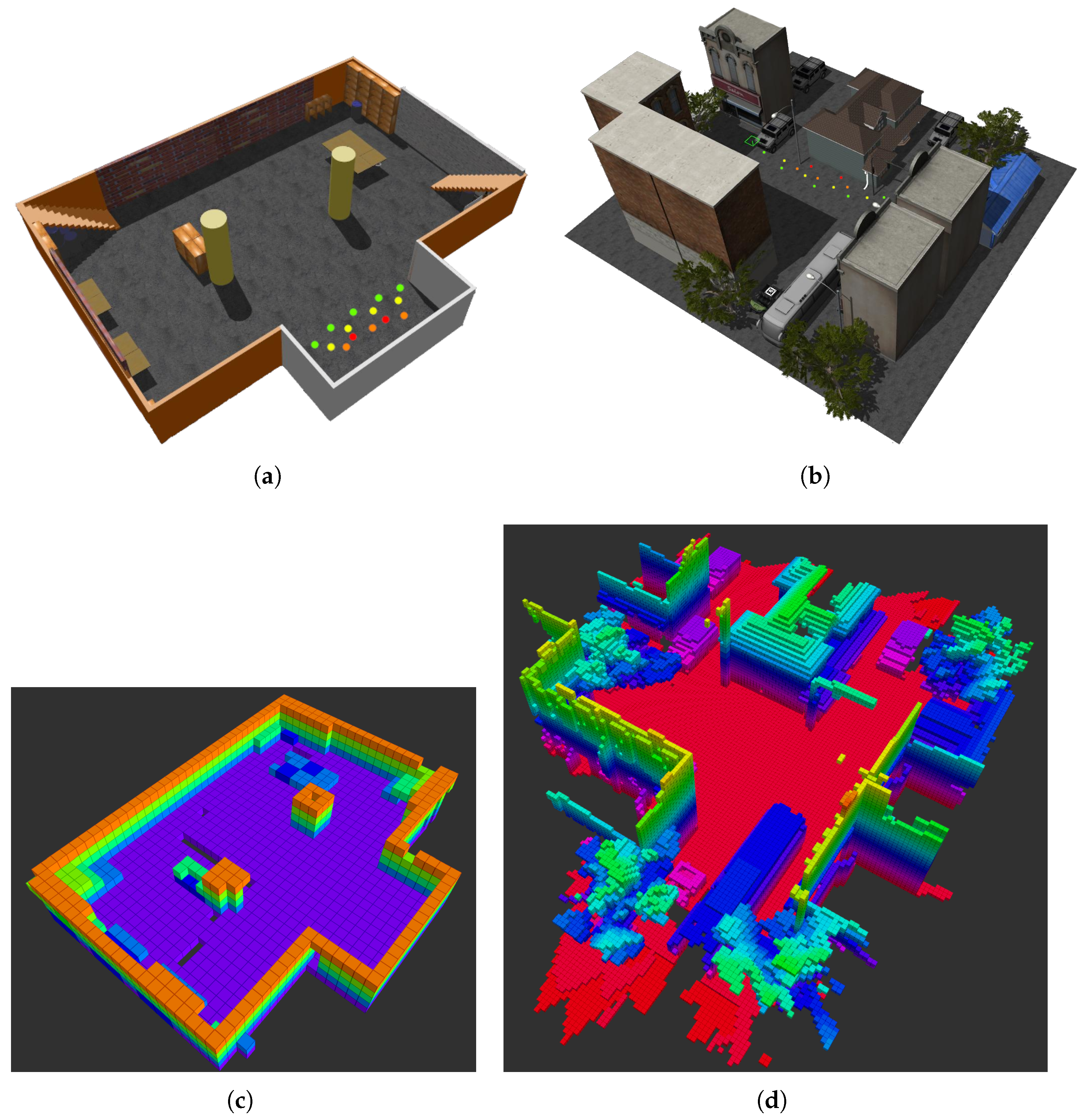
5.1. Indoor Scenario

For the indoor scenario, a regular single-story space with limited furniture and weighing structures but no other obstacles was used with dimensions of 20 × 12 × 3 m 3 , as shown in Figure 5a. The proposed method was tested 20 times on teams consisting of 2, 3, 4, and 5 UAVs with the same initial position, where the relative distances between UAVs were less than 50 cm . Each UAV was equipped with a depth camera, and the maximum length of RRT was set to 1 m , while the maximum sensor range was d max sensor = 4 m . The partition constraint became invalid when iterative tree nodes reached a threshold, N T > N t h r e s h o l d = 30 , and exploration also stopped when N T > N M A X = 150 . The minimum node number of each RRT iteration was N i n i t = 15 , and the space within the maximum planner range of d max planner = 2.5 m was used to calculate the gain, with the value of λ set to 0.5 .
To evaluate efficiency, the exploration completion time was measured using a team of 5 UAVs as shown in Figure 6a. The exploration completion degree was plotted over time to reflect the exploration process, as depicted in Figure 6b. The results showed that with an increase in the number of UAVs, the exploration time decreased for all of the methods, albeit at a lower rate of decline for larger teams. For two UAVs, the proposed and Voronoi methods show similar performance with mean values of 185.4 s and 191.8 s , respectively. For a team of 5 UAVs, our proposed method outperformed other methods with lower variance and mean values of 86.2 s , while the voronoi, coordination, and greedy methods took 98 s , 125.5 s , and 185.4 s , respectively. The proposed method ensured efficient exploration with fewer scan repetitions by spacing out UAVs, which led to less backtracking and smaller variance. On the other hand, more space would be allocated to the UAVs that detect fewer tasks in our method, thus resulting in overall efficiency.
In addition, Figure 6b showed a turning point during exploration, where the speed of exploration began to differ at about 50 s . The proposed method experienced the exploration bottleneck later than the voronoi, coordination, and greedy methods, respectively. The greedy method failed to cooperate, leading to multiple UAVs exploring the same area, and scan repetitions. Although the coordination method cooperated through a designed gain, it could not avoid scan repetitions. The Voronoi-based partition method restricted individual UAVs to their partitioned areas without considering detection efficiency for unknown spaces, and this could cause UAVs to fall idle when such areas became fewer.

5.2. Large Outdoor Scenario

The second scenario involves an outdoor space measuring 40 × 40 × 9 m 3 , which is a typical urban community with multiple buildings and complex spatial structures, including spatial dead ends, as shown in Figure 5b. Since the outdoor environment is more extensive, the maximum length of the RRT planner is set to 3 m based on empirical experiments. During the trials, many depth value frames exceeding 7 m were observed, and the trial settings were adjusted to d max sensor = 8.5 m with a mounting pitch of 35 to obtain more ground measurements, where d max planner = 3.5 m with N i n i t = 30 , N t h r e s h o l d = 80 , and N M A X = 250 .
For each planner, 20 trials were conducted for teams consisting of 2, 3, 4, and 5 UAVs, starting from the same initial position, where the relative distances between UAVs were less than 100 cm . Similar to the indoor scenario, the results of the algorithms (indicated in Figure 7) show that the proposed method outperforms the voronoi, coordination, and greedy methods, with a mean completion time of 376.7 s for a team of 5 UAVs. In contrast, the voronoi, coordination, and greedy methods gave mean completion times of 428.8 s , 657.8 s , and 771.5 s , respectively. The experiment also shows that as the scenario size increases, the greedy method, without cooperation, becomes increasingly random and unintelligent. The variance of the results is significantly larger in the outdoor scenario.
In both scenarios, the exploration completion rate exhibits a decreasing trend. This trend can be attributed to the fact that at the start of the exploration, there were many unknown areas, and the UAVs can find enough task points with fewer sampling times. Regardless of the efficiency of the planning algorithm, the UAVs could detect unknown spaces that were not pre-included in the planning, which could lead to efficient exploration in the beginning. As the environment has been continuously explored, the unknown area has decreased, and the time required to calculate the targets has become longer. Especially with the use of the receding horizon method, the UAVs often re-visited those optimal targets due to being confined to local optima, which would slow down the rate of exploration at the later stage.

6. Evaluation in Practical Experiments

To further validate the proposed method, practical indoor experiments were conducted with three self-assembly UAVs equipped with depth cameras flying in a room with obstacles, as shown in Figure 8b. A 10 × 8 × 3 m 3 bounding box was used to constrain the space for exploration. Due to the UAV structure, the cameras could only be mounted with a downward pitch angle of 5 on the front side, and the UAVs’ precise location was ensured through the use of VICON, a motion capture system, for safe piloting. Parameter values for the practical experiments were set based on the simulation experiments conducted for the indoor scenario. Although limitations such as hardware restrictions, network bandwidth, and flight trajectory control were not the primary focus of this paper, multiple trials were carried out to ensure the proposed method’s usability. Table 1 summarizes some of the critical parameters employed in the practical experiments.
The proposed algorithm was tested in a practical experiment involving a team of three UAVs, as shown in Figure 8. The UAVs were initially positioned closely together on the same side of the exploration area, which is typical for real deployments. The exploration process was repeated 20 times, with a maximum exploration time of 232.2 s , a minimum of 194.6 s , and an average of 209.4 s . The decentralized nature of the planner ensures that the UAVs can perform their tasks robustly, with interruptions to one UAV having no impact on the work of others, as demonstrated in Figure 9. The effectiveness and usability of the proposed method in a practical scenario are demonstrated by the exploration maps at six different sampling times, as shown in Figure 10. The virtual centroid in three colors dynamically changes during the exploration process, and the working area of each UAV is partitioned reasonably and iteratively. The UAV denoted as the yellow on the left moves gradually to the lower-left area after completing its task in the upper-left corner and collaborates with the UAV in the lower-right section to adjust the task areas. In the final map of Figure 10, the gap areas on the ground were detected, which were affected by the range of the depth camera. We can assume that using more robust sensors such as 3D LiDAR could alleviate this phenomenon, but such an approach requires greater consideration of the comprehensiveness of the experimental system and its applicability to different settings, which needs to be further considered in future research.

7. Conclusions and Future Work

To improve the efficiency and reliability of cooperative exploration in unknown environments, a dynamic centroid-based area partition method has been implemented in this study, which takes into account both position and task information throughout the process. This method assigns more space to UAVs that detect fewer tasks, which ensures that each UAV undertakes the exploration mission evenly. Additionally, an NBV exploration method has been improved by sampling candidates in their partitioned area and formulating the weight, which also quantifies the task. The proposed method has been compared to three other methods in two simulation environments and found to be faster than traditional methods. Practical experiments have also demonstrated the effectiveness of this approach. However, the randomness of the sampling process introduces variability, which could lead to local minima. This sampling uncertainty, resulting in an unreasonable partition, prevents us from providing a stable and precise exploration process description in different trials with the same setting. To address this issue, future research will investigate the use of frontier-based methods that provide an accurate number of tasks, allowing for more rational partitioning results. Additionally, alternative sensing methods or equipment could be considered to enhance the perception of swarm UAVs.

Author Contributions

Conceptualization, J.G. and B.D.; methodology, J.G. and T.Y.; software, T.Y.; validation, T.Y., J.G. and X.Z.; formal analysis, T.Y. and J.G.; investigation, J.G.; resources, X.Z. and W.Y.; data curation, T.Y. and J.G.; writing—original draft preparation, T.Y.; writing—review and editing, J.G.; visualization, J.G.; supervision, B.D and W.Y.; project administration, B.D.; funding acquisition, B.D. All authors have read and agreed to the published version of the manuscript.

Funding

This work was supported by the National Natural Science Foundation of China (No. 61902423).

Data Availability Statement

Data available on request from the authors.

Conflicts of Interest

The authors declare no conflict of interest.

References

  1. Cieslewski, T.; Kaufmann, E.; Scaramuzza, D. Rapid exploration with multi-rotors: A frontier selection method for high speed flight. In Proceedings of the 2017 IEEE/RSJ International Conference on Intelligent Robots and Systems (IROS), Vancouver, BC, Canada, 24–28 September 2017; pp. 2135–2142. [Google Scholar] [CrossRef]
  2. Wang, C.; Chi, W.; Sun, Y.; Meng, M.Q.H. Autonomous Robotic Exploration by Incremental Road Map Construction. IEEE Trans. Autom. Sci. Eng. 2019, 16, 1720–1731. [Google Scholar] [CrossRef]
  3. Xu, Z.; Deng, D.; Shimada, K. Autonomous UAV Exploration of Dynamic Environments Via Incremental Sampling and Probabilistic Roadmap. IEEE Robot. Autom. Lett. 2021, 6, 2729–2736. [Google Scholar] [CrossRef]
  4. Jung, S. Bridge Inspection Using Unmanned Aerial Vehicle Based on HG-SLAM: Hierarchical Graph-Based SLAM. Remote Sens. 2020, 12, 3022. [Google Scholar] [CrossRef]
  5. Wang, J.; Wu, Y.X.; Chen, Y.Q.; Ju, S. Multi-UAVs collaborative tracking of moving target with maximized visibility in urban environment. J. Frankl. Inst. 2022, 359, 5512–5532. [Google Scholar] [CrossRef]
  6. Pan, T.; Gui, J.; Dong, H.; Deng, B.; Zhao, B. Vision-Based Moving-Target Geolocation Using Dual Unmanned Aerial Vehicles. Remote Sens. 2023, 15, 389. [Google Scholar] [CrossRef]
  7. Hu, J.; Niu, H.; Carrasco, J.; Lennox, B.; Arvin, F. Voronoi-Based Multi-Robot Autonomous Exploration in Unknown Environments via Deep Reinforcement Learning. IEEE Trans. Veh. Technol. 2020, 69, 14413–14423. [Google Scholar] [CrossRef]
  8. Simmons, R.; Apfelbaum, D.; Burgard, W.; Fox, D.; Moors, M.; Thrun, S.; Younes, H. Coordination for Multi-Robot Exploration and Mapping; AAAI Press: Palo Alto, CA, USA, 2020; pp. 852–858. [Google Scholar]
  9. Yu, J.; Tong, J.; Xu, Y.; Xu, Z.; Dong, H.; Yang, T.; Wang, Y. SMMR-Explore: SubMap-based Multi-Robot Exploration System with Multi-robot Multi-target Potential Field Exploration Method. In Proceedings of the 2021 IEEE International Conference on Robotics and Automation (ICRA), Xi’an, China, 30 May–5 June 2021; pp. 8779–8785. [Google Scholar] [CrossRef]
  10. Masaba, K.; Li, A.Q. GVGExp: Communication-Constrained Multi-Robot Exploration System based on Generalized Voronoi Graphs. In Proceedings of the 2021 International Symposium on Multi-Robot and Multi-Agent Systems (MRS), Cambridge, UK, 4–5 November 2021; pp. 146–154. [Google Scholar] [CrossRef]
  11. Mannucci, A.; Nardi, S.; Pallottino, L. Autonomous 3D Exploration of Large Areas: A Cooperative Frontier-Based Approach. In Proceedings of the Modelling and Simulation for Autonomous Systems, Rome, Italy, 24–26 October 2017; Mazal, J., Ed.; Springer International Publishing: Cham, Switzerland, 2018; pp. 18–39. [Google Scholar] [CrossRef]
  12. Bircher, A.; Kamel, M.; Alexis, K.; Oleynikova, H.; Siegwart, R. Receding Horizon “Next-Best-View” Planner for 3D Exploration. In Proceedings of the 2016 IEEE International Conference on Robotics and Automation (ICRA), Stockholm, Sweden, 16–21 May 2016; pp. 1462–1468. [Google Scholar] [CrossRef]
  13. Lindqvist, B.; Agha-Mohammadi, A.A.; Nikolakopoulos, G. Exploration-RRT: A multi-objective Path Planning and Exploration Framework for Unknown and Unstructured Environments. In Proceedings of the 2021 IEEE/RSJ International Conference on Intelligent Robots and Systems (IROS), Prague, Czech Republic, 27 September–1 October 2021; pp. 3429–3435. [Google Scholar] [CrossRef]
  14. Hornung, A.; Wurm, K.M.; Bennewitz, M.; Stachniss, C.; Burgard, W. OctoMap: An efficient probabilistic 3D mapping framework based on octrees. Auton. Robot. 2013, 34, 189–206. [Google Scholar] [CrossRef]
  15. Yu, T.; Deng, B.; Gui, J.; Zhu, X.; Yao, W. Efficient Informative Path Planning via Normalized Utility in Unknown Environments Exploration. Sensors 2022, 22, 8429. [Google Scholar] [CrossRef] [PubMed]
  16. Ju, S.; Wang, J.; Dou, L. MPC-Based Cooperative Enclosing for Nonholonomic Mobile Agents Under Input Constraint and Unknown Disturbance. IEEE Trans. Cybern. 2023, 53, 845–858. [Google Scholar] [CrossRef]
  17. Fox, D.; Jonathan, K.O.; Konolige, K.; Limketkai, B.; Schulz, D.; Stewart, B. Distributed Multirobot Exploration and Mapping. Proc. IEEE 2006, 94, 1325–1339. [Google Scholar] [CrossRef]
  18. Tang, Y.; Chen, Y.; Zhou, D. Measuring uncertainty in the negation evidence for multi-source information fusion. Entropy 2022, 24, 1596. [Google Scholar] [CrossRef] [PubMed]
  19. Hardouin, G.; Moras, J.; Morbidi, F.; Marzat, J.; Mouaddib, E.M. Next-Best-View planning for surface reconstruction of large-scale 3D environments with multiple UAVs. In Proceedings of the 2020 IEEE/RSJ International Conference on Intelligent Robots and Systems (IROS), Las Vegas, NV, USA, 24 October 2020–24 January 2021; pp. 1567–1574. [Google Scholar] [CrossRef]
  20. Oleynikova, H.; Taylor, Z.; Fehr, M.; Siegwart, R.; Nieto, J. Voxblox: Incremental 3D Euclidean Signed Distance Fields for on-board MAV planning. In Proceedings of the 2017 IEEE/RSJ International Conference on Intelligent Robots and Systems (IROS), Vancouver, BC, Canada, 24–28 September 2017; pp. 1366–1373. [Google Scholar] [CrossRef]
  21. Li, H.; Tsukada, M.; Nashashibi, F.; Parent, M. Multivehicle Cooperative Local Mapping: A Methodology Based on Occupancy Grid Map Merging. IEEE Trans. Intell. Transp. Syst. 2014, 15, 2089–2100. [Google Scholar] [CrossRef]
  22. Corah, M.; O’Meadhra, C.; Goel, K.; Michael, N. Communication-Efficient Planning and Mapping for Multi-Robot Exploration in Large Environments. IEEE Robot. Autom. Lett. 2019, 4, 1715–1721. [Google Scholar] [CrossRef]
  23. Schmid, L.; Reijgwart, V.; Ott, L.; Nieto, J.; Siegwart, R.; Cadena, C. A Unified Approach for Autonomous Volumetric Exploration of Large Scale Environments Under Severe Odometry Drift. IEEE Robot. Autom. Lett. 2021, 6, 4504–4511. [Google Scholar] [CrossRef]
  24. Zhou, B.; Zhang, Y.; Chen, X.; Shen, S. FUEL: Fast UAV Exploration Using Incremental Frontier Structure and Hierarchical Planning. IEEE Robot. Autom. Lett. 2021, 6, 779–786. [Google Scholar] [CrossRef]
  25. Lee, E.M.; Choi, J.; Lim, H.; Myung, H. REAL: Rapid Exploration with Active Loop-Closing toward Large-Scale 3D Mapping using UAVs. In Proceedings of the 2021 IEEE/RSJ International Conference on Intelligent Robots and Systems (IROS), Prague, Czech Republic, 27 September–1 October 2021; pp. 4194–4198. [Google Scholar] [CrossRef]
  26. Zhu, H.; Cao, C.; Xia, Y.; Scherer, S.; Zhang, J.; Wang, W. DSVP: Dual-Stage Viewpoint Planner for Rapid Exploration by Dynamic Expansion. In Proceedings of the 2021 IEEE/RSJ International Conference on Intelligent Robots and Systems (IROS), Prague, Czech Republic, 27 September–1 October 2021; pp. 7623–7630. [Google Scholar] [CrossRef]
  27. Schmid, L.; Pantic, M.; Khanna, R.; Ott, L.; Siegwart, R.; Nieto, J. An Efficient Sampling-Based Method for Online Informative Path Planning in Unknown Environments. IEEE Robot. Autom. Lett. 2020, 5, 1500–1507. [Google Scholar] [CrossRef]
  28. Charrow, B.; Kahn, G.; Patil, S.; Liu, S.; Goldberg, K.; Abbeel, P.; Michael, N.; Kumar, V. Information-Theoretic Planning with Trajectory Optimization for Dense 3D Mapping. In Proceedings of the Robotics: Science and Systems, Rome, Italy, 13–17 July 2015; Volume 11, pp. 3–12. [Google Scholar] [CrossRef]
  29. Li, S.; Tian, B.; Zhu, X.; Gui, J.; Yao, W.; Li, G. InTEn-LOAM: Intensity and Temporal Enhanced LiDAR Odometry and Mapping. Remote Sens. 2022, 15, 242. [Google Scholar] [CrossRef]
Figure 1. System framework. The modules of localization, mapping, partition, and planning are run independently in each UAV. All of the working UAVs connect to a 5G WiFi for information exchange. Poses and platform weights are shared to dynamically adjust the partition areas. The details of partition and weight calculation are discussed in Section 4.
Drones 07 00337 g001
Figure 2. The partitioning process of UAV j . Each UAV computes a virtual centroid, and a 3D self-responsible area is partitioned by the nearest two planes P , defined by partition rays P r and the axis of the centroid.
Drones 07 00337 g002
Figure 3. Distributed ray-cast mapping. As (a) shows, three small axes represent the UAV, and the big axis represents the origin of a unified coordinate system. The depth measurement is visualized by point clouds of various colours, where blue denotes objects that are far away and red indicates those that are in close proximity. As the UAV wander, (b) shows the map expressed by Octomap simultaneously.
Drones 07 00337 g003
Figure 4. The planning process of UAV j . The d j and d j 1 are calculated to formulate the factor f j and f j 1 .
Drones 07 00337 g004
Figure 5. Simulation environments and their exploration results. (a) A 20 × 12 × 3 m 3 indoor scenario, a regular single-story space; (b) a 40 × 40 × 9 m 3 outdoor scenario, a typical urban community. The colored points on the floor represent the initial positions of UAVs, with red indicating 2 UAVs, orange for 3 UAVs, yellow for 4 UAVs, and green for 5 UAVs. (c,d) are the exploration results for both scenarios. (The following figures in this paper have the same meaning, where the spatial structure and depth information are depicted using grids of different colours.)
Drones 07 00337 g005
Figure 6. Numerical analysis of indoor simulation. (a) shows the exploration time of a team with 2, 3, 4, and 5 UAVs. (b) shows the team of 5 UAVs in one trial. Three other algorithms are compared.
Drones 07 00337 g006
Figure 7. Numerical analysis of outdoor simulation. (a) shows the exploration time of the team with 2, 3, 4, and 5 UAVs. (b) shows the team of 5 UAVs in one trial. Three other algorithms are compared.
Drones 07 00337 g007
Figure 8. The practical experiments. (a) shows the initial status of three UAVs; they are placed on the same side of a room. (b) shows three UAVs are performing exploration in one trial; a 10 × 8 × 3 m 3 virtual boundary is set to bound the exploring space.
Drones 07 00337 g008
Figure 9. Robust coordination case. (a) shows UAV represented by the red arrow has stopped exploring due to insufficient power at an early stage; (b) shows other UAVs continue to finish the task. The yellow one helps the red to explore the bottom right corner of this environment.
Drones 07 00337 g009
Figure 10. The mapping process of one practical experiment. The sampling times display the complete process of three UAVs collaborating on exploration, with each UAV’s designated area being continuously updated. The UAV represented by the yellow icon on the left gradually moves towards the lower region, collaborating with the other UAVs to adjust the exploration area. In the final map, gaps on the ground were influenced by the depth camera’s perception range. It is assumed that using more powerful sensors such as 3D LiDAR [29] may mitigate this phenomenon, but this approach necessitates further consideration of the experimental system’s applicability.
Drones 07 00337 g010
Table 1. Important parameters in practical experiments.
ParameterValueParameterValue
v max 0.1 m / s ψ ˙ max 0.5 rad / s
d max planner 1.5 m d max sensor 2.5 m
λ 0.5 MaxTreeLength 0.8 m
N i n i t 10 N M A X 100
N t h r e s h o l d 30Mounting pitch 5
Disclaimer/Publisher’s Note: The statements, opinions and data contained in all publications are solely those of the individual author(s) and contributor(s) and not of MDPI and/or the editor(s). MDPI and/or the editor(s) disclaim responsibility for any injury to people or property resulting from any ideas, methods, instructions or products referred to in the content.

