Article

Fatigue Characteristics of Steel–Concrete Composite Beams

1
Department of Engineering and Technology, Texas A&M University-Commerce, Commerce, TX 75429, USA
2
Department of Civil and Environmental Engineering, University of Missouri, Columbia, MO 65211-2200, USA
3
Department of Structural Engineering, Zagazig University, Zagazig 44519, Egypt
4
Engineering Management Department, College of Engineering, Prince Sultan University, Riyadh 11586, Saudi Arabia
*
Author to whom correspondence should be addressed.
Infrastructures 2024, 9(2), 29; https://doi.org/10.3390/infrastructures9020029
Submission received: 15 December 2023 / Revised: 31 January 2024 / Accepted: 2 February 2024 / Published: 4 February 2024

Abstract

:
Fatigue in steel–concrete composite beams can result from cyclic loading, causing stress fluctuations that may lead to cumulative damage and eventual failure over an extended period. In this paper, the experimental findings from fatigue loading tests on composite beams with various arrangements are presented. Fatigue tests were performed up to 1,000,000 cycles using four-point loading, encompassing various ranges of shear stress at a consistent amplitude. Additionally, the effects of external post-tensioning and the strength of the shear connection were investigated. Static tests were run until failure to assess the enduring strength of the specimens subjected to fatigue. The cyclic mid-span deflections, slippages, and strains were measured during the testing. Based on the experimental findings, it was found that the damage region that the shear studs caused in the concrete slab, which resulted in a reduction in stiffness within the shear connection, grew as the loading cycles increased, leading to an increase in residual deflections and plastic slippages. Controlling the longitudinal fatigue cracks in the concrete slab was largely dependent on the strength of the shear connection between the steel beams and concrete slabs. Moreover, the applied fatigue loading range affected the propagation and distribution of fatigue cracks in the concrete slab. The strains in different parts of the composite specimens were significantly reduced by applying the external post-tensioning. With no signs of distress at the anchors, the tendons displayed excellent fatigue performance.

1. Introduction

Harnessing the advantages of synergizing component materials to craft efficient and lightweight structural components, steel–concrete composite beams are frequently utilized for bridge superstructures. Shear connections enable the composite activity between the concrete slab and steel beam. The level of shear connectivity between the two main components (concrete slab and steel beam) is a key factor in determining the structural behavior of this type of beam. Depending on this level, full and partial shear connections can be created. The composite beam capacity can be efficiently increased by external post-tensioning utilizing high-strength steel cables [1]. For elevated levels of prestressing force, the composite member tends to exhibit characteristics resembling a shallow arc with horizontal elastic support, resulting in enhanced flexural behavior. However, it is important to note that this condition may lead to the exceedance of the yield stress. Steel–concrete composite beam bridges are prone to fatigue loading under service loads, which might result in an early failure. Furthermore, the synergistic impact of stud corrosion and beam fatigue plays a crucial role in influencing the overall performance of a composite beam [2]. As stud corrosion rates increase, the damage mode of the beams transitions from stud shearing to concrete crushing. Additionally, several mechanical indicators exhibit a nonlinear degradation trend, underscoring the substantial effects of these combined factors.
Previous studies on the fatigue performance of steel–concrete composite beams have been conducted. In order to evaluate the impacts of various shear connection gradations on the static and fatigue performances of the beams, steel–concrete composite beams were used [3]. With a reduction in the level of shear connectivity, the monotonic and fatigue mechanical parameters of these beams diminish, and their failure modes also alter. Through experimental and theoretical research, Wang et al. [4] looked into the enduring load-bearing capability of steel–concrete composite beams subjected to high-cycle fatigue loading. Under the specified fatigue load, the number of cycles appears to have the most impact on the failure mode of the composite beams. The failure mode changes from stud cutting to mid-span concrete crushing as the number of fatigue loadings rises. Through push-out tests, Xu et al. [5] experimentally examined the fatigue behaviors of headed shear studs. The analysis was done on the cyclic strain evolution and fatigue failure mechanisms of the specimens. After achieving its maximal value with the loading cycles, the strain at the shear stud with fatigue damage exhibits a steadily rising trend. Additionally, the number of cycles results in a quick rise in the residual deformations of the composite beams at the beginning and end of the fatigue life, but a linear increase throughout the remainder of the fatigue life [6]. According to the test results, concrete cracks have little effect on fatigue life, but stud damage has a significant impact [7]. Compared to static qualities, the stud’s damage had a bigger impact on fatigue performances. The strategic placement and degree of composite action achieved by shear connectors played pivotal roles in effectively mitigating the development of longitudinal cracks in concrete slabs under fatigue loading conditions [8]. Enhancing the initial prestressing force demonstrated a notable enhancement in beam capacity compared to strengthened beams [9]. Nevertheless, diminishing returns were observed in the incremental increase of the prestressing force. Post-tensioning effectively preserved the stability of beams beyond the ultimate point, altering the failure mode from yielding followed by concrete crushing at a higher load to a scenario where yielding and crushing occurred at approximately the same level of loading [10].
Hassanin et al. [11] used the ANSYS (Workbench) software program to create a finite element model that was subjected to cyclic loading in order to determine the cyclic behavior of steel–concrete composite beams in locations with positive bending moments. In order to prevent an early loss of composite action and a resulting reduction in the fatigue life of the beam, it is preferred that the value of the level of shear connectivity during fatigue loading be not less than 80%. El-Zohairy and Salim [12] looked at the effects of several strengthening characteristics, such as the level of shear connectivity, tendon eccentricity, tendon length, and the effect of post-tensioning on restoring the flexural behavior of an overloaded beam and draped vs. straight tendons. External PT application over the whole length of the beam prolongs the fatigue life of the composite beam by decreasing the development of fatigue fractures, which invariably begin at stress raisers.
The review of the prior literature revealed that push-out tests were mostly used in the thorough investigations of the fatigue performance of shear connections, which addressed a shortage of recorded data based on real composite beams. According to El-Zohairy et al. [13], push-out tests cannot accurately depict the true behavior of steel–concrete composite beams, which have an impact on the fatigue performance of the concrete slabs, steel beams, and shear connectors. The fatigue property of these beams has therefore been thoroughly experimentally investigated in this research, taking into account the effects of the level of shear connectivity, external post-tensioning, and the placement of shear connectors.

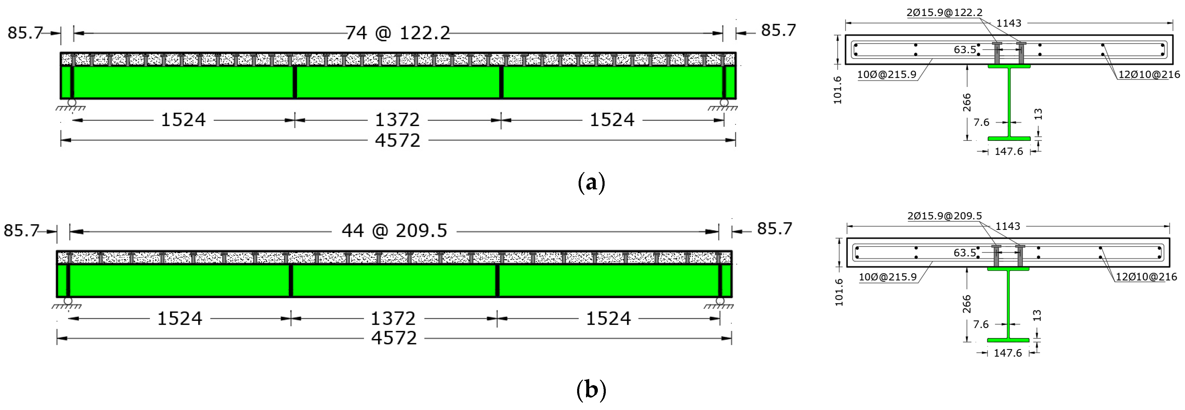
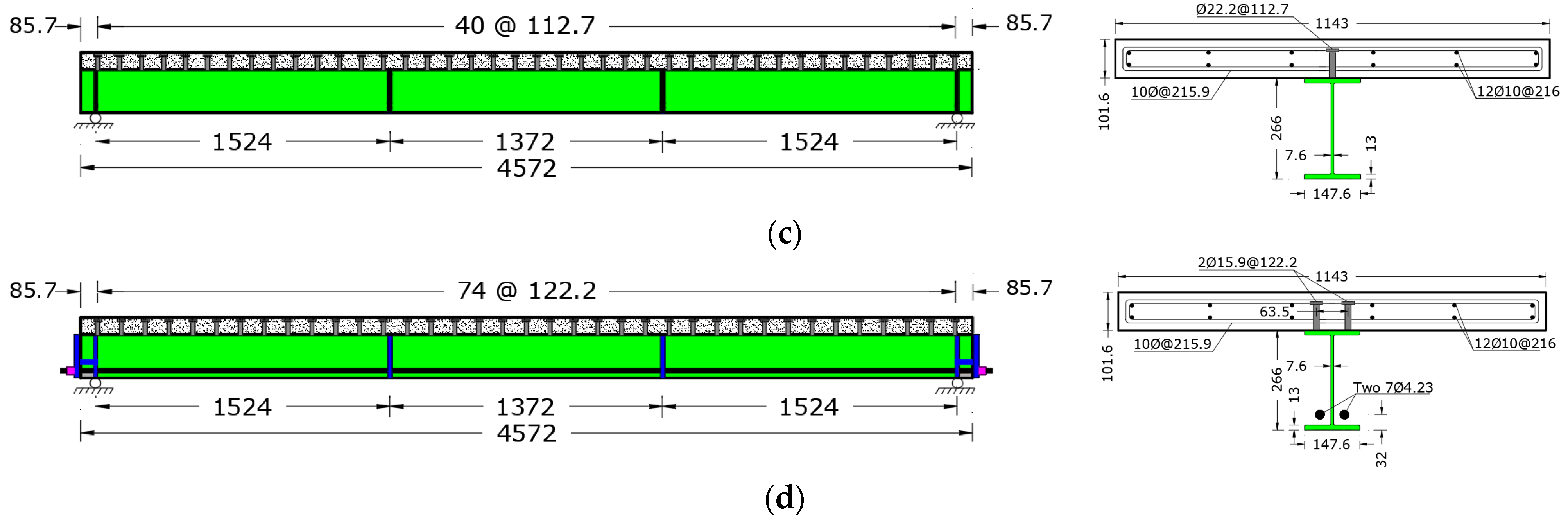
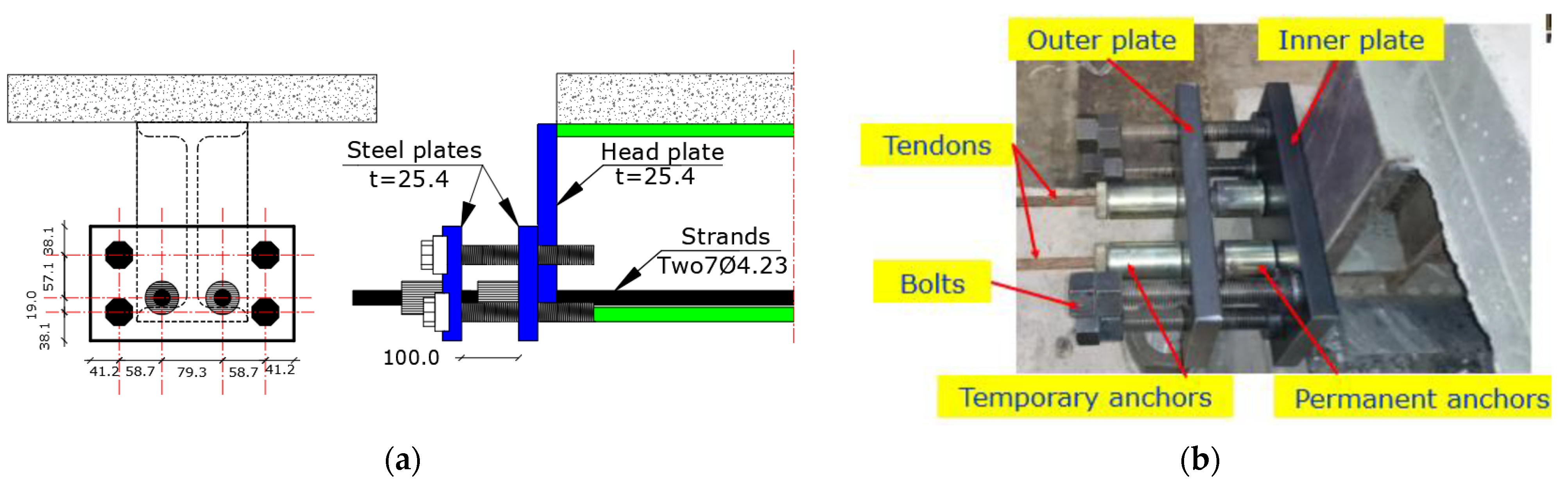
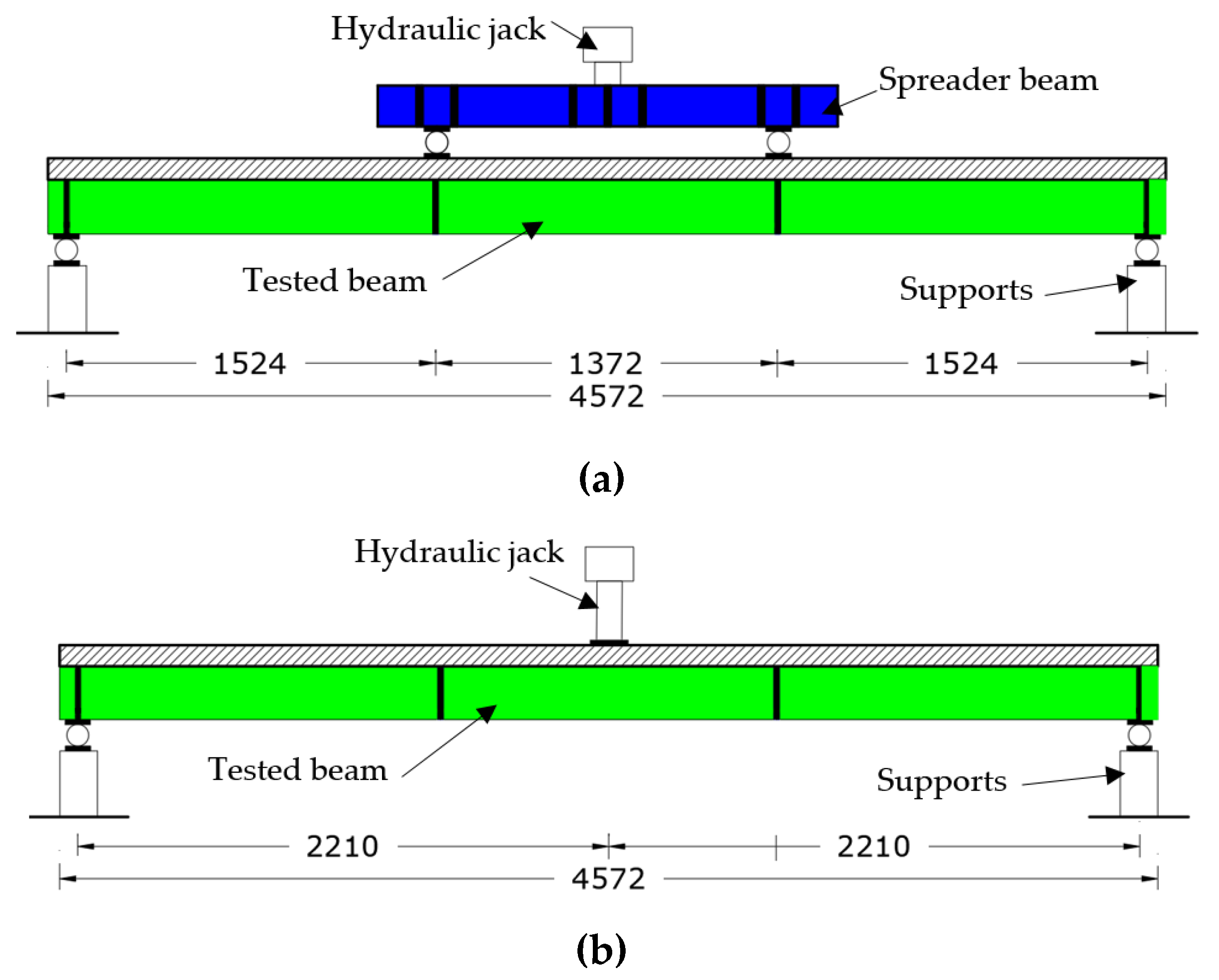
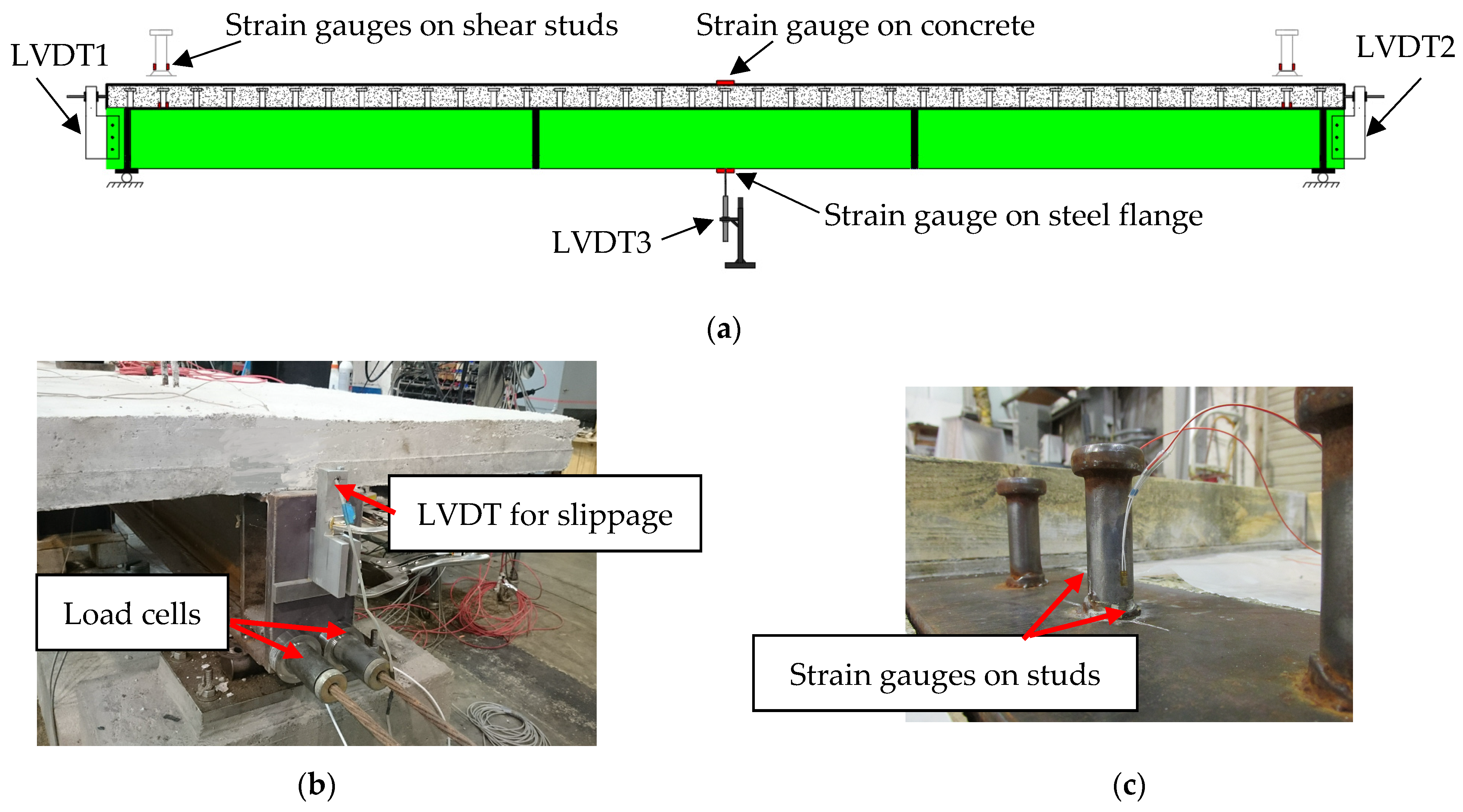
2. Experimental Program

Steel–concrete composite beams with simple support were created and tested in order to examine the fatigue characteristics and enduring strength of composite beams subjected to sagging moments. The tested span between supports was 4419.6 mm, while the entire length was 4572 mm (see Figure 1). The concrete slab measured 101.6 mm in thickness and 1143 mm in breadth. Deformed rebars of 10 mm in diameter were used to strengthen the concrete slab in both the longitudinal and transverse orientations (see Table 1). To accomplish the interactive synergy between steel beams and concrete slabs, headed stud connectors were welded onto the top flange of the steel beam, featuring longitudinal and transverse spacing as listed in Table 1. This was done to attain varying levels of shear connectivity per AASHTO LRFD [14], as shown in Figure 1 and summarized in Table 1. The AASHTO LRFD [14] guidelines were applied to determine the necessary number of connectors essential for withstanding the complete longitudinal shear force between the concrete slab and steel beam. The full shear connection was achieved for all specimens, except specimen FSB 4, where a partial shear connection (60%) was obtained. For the specimen with partial shear connection, a broader spacing of connectors was achieved by employing 60% of the required studs, as opposed to the full-composite specifications observed in other specimens. This specific shear connection design was chosen to mitigate any premature failure in the connection between the steel beam and concrete slab. The headed stud connectors were organized in two rows with a transverse spacing of 63.5 mm, a diameter of 15.9 mm, and a height of 81 mm for all specimens, except for specimen FSB 5. In this particular case, shear connectors with a larger size (22.2 mm in diameter and 81 mm in height) were utilized and arranged in a single row to establish the connection between the concrete slab and steel beam.
To provide reference data for the fatigued specimens without and with external post-tensioning, respectively, specimens RSB 1 and PRSB 6 were solely examined under static stress. The relationship between the range of shear stress exhibited by the headed connectors and the corresponding loading cycles adopted by the AASHTO specification, which was projected to fracture at 1,000,000 cycles, was used to produce the applied fatigue loads. As a result, these 1,000,000 cycles were maintained constantly for all specimens for comparison purposes to explore the impact of pre-damage caused by fatigue loading on the enduring strength of the composite specimens.
Post-tensioning was done on specimens PRSB 6 and FPSB 7 after the concrete had fully developed its strength. For post-tensioning, two 7Ø4.23 mm high-strength strands with nominal cross sections of 98.7 mm2 each were employed. The strands stretched the whole length of the specimen and were situated above the tension steel flange (32 mm), as shown in Figure 1d. According to AASHTO, each strand was post-tensioned to an average of 85 kN (46% of its maximum strength). Applying post-tensioning force required assemblies at both ends of the specimen. This post-tensioning configuration included two separate assemblies: the active end, where the post-tensioning force was applied to the tendons (see Figure 2), and the dead end, corresponding to the opposite gripped end of the tendon. Wedge-type steel anchors were securely fastened the post-tensioned tendons, tensioned by four bolts rotating on thrust bearings, and positioned between two rigid steel plates (refer to Figure 2). The application of post-tensioning force involved the simultaneous tightening of the four bolts, generating force against a pair of anchors at each tendon’s ends. This simultaneous post-tensioning process occurred as the outer steel plate moved away from the specimen end. Additionally, another pair of anchors, situated between the two steel plates, served as the active end upon reaching the required post-tensioning force, facilitating the release of the outer steel plate.
The servo-hydraulic actuator used for static and fatigue testing has a maximum capacity of 890 kN. The tests were run in two phases, with the first stage consisting of a fatigue test at a loading rate of 4.0 cycles per second and a total number of cycles of 1,000,000 cycles, as listed in Table 2. The second stage consisted of the final static loading test at a loading rate of 15 kN/minute. During the fatigue loading (first stage), a spreader beam was utilized to evenly distribute the applied point load to two distinct loading points, as schematically shown in Figure 3a. However, the residual behavior of the fatigued specimens was explored by conducting static tests under a single-point load until failure, as shown in Figure 3b.
Linear variable differential transformers (LVDTs) were utilized to record the slippage at the beam ends, as well as the vertical deflection at mid-spans for each specimen, as illustrated in Figure 4a. By utilizing strain gauges that were adhered directly to various areas of each specimen, strain measurements were taken. By utilizing strain gauges, the headed connectors at the ends of the specimens were instrumented. At the bottom of each connector, two strain gauges were glued to track the compressive and tensile stresses on both sides (see Figure 4). Additionally, the steel beams and concrete slabs were tested for strains at the mid-spans. Load cells were used to measure the external post-tensioning during the fatigue and static loadings for specimens PRSB6 and PFSB 7, as shown in Figure 4.
All specimens were cast in normal-weight concrete. For each specimen, three 100 mm 200 mm concrete cylinders were formed during the concrete casting process in order to conduct compressive strength testing. After 28 days, the nominal concrete compressive strength, on average, reached 32.4 MPa. Tension tests were carried out in accordance with ASTM A370 [15] to ascertain the properties of the steel reinforcement. Table 3 provides an overview of the mechanical characteristics of the steel types.’

3. Results and Discussions

The crack propagation in the concrete slabs, as well as the cyclic deformations and strains, were used to reflect the characteristics of the composite specimens during the fatigue testing.

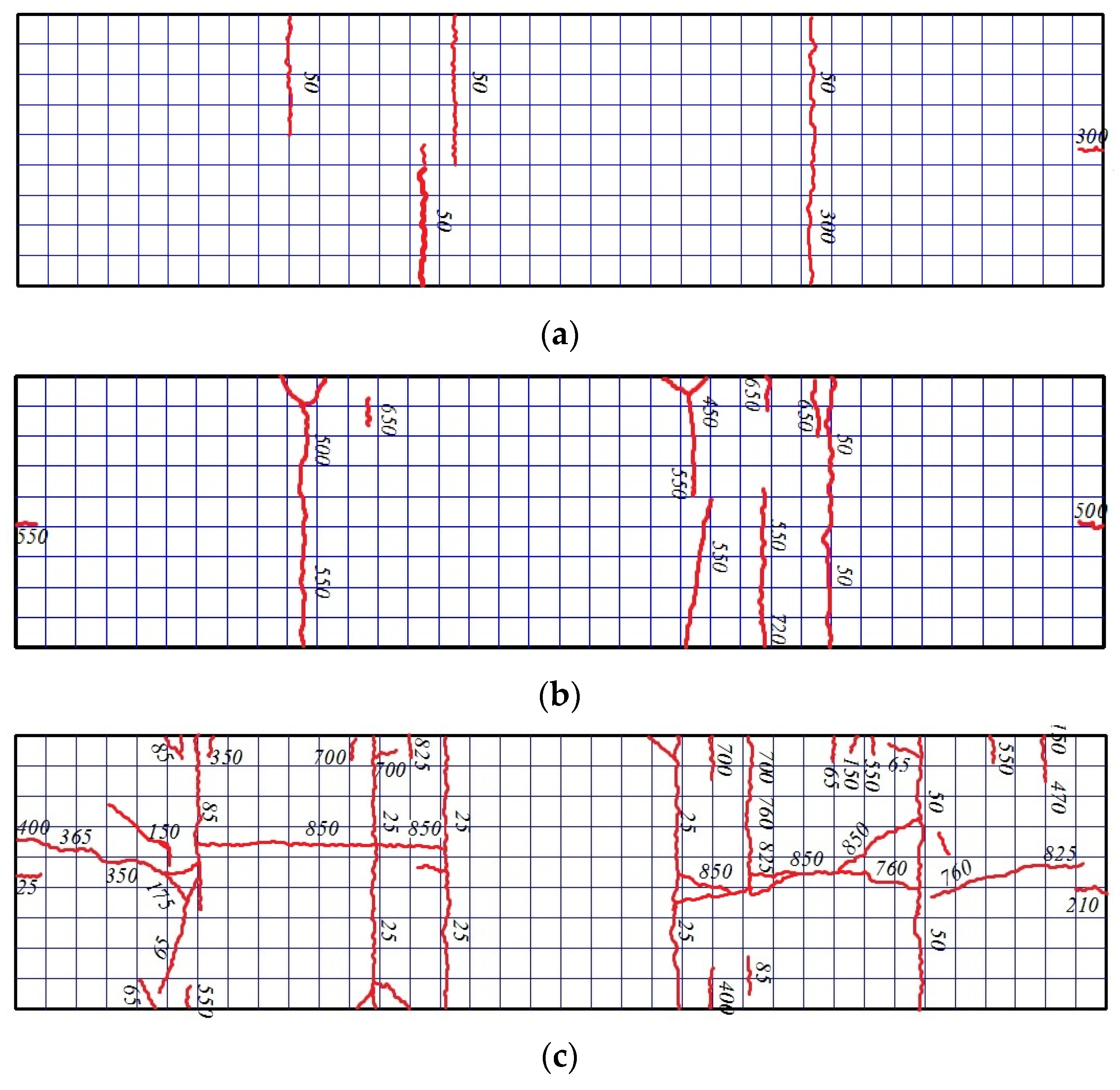
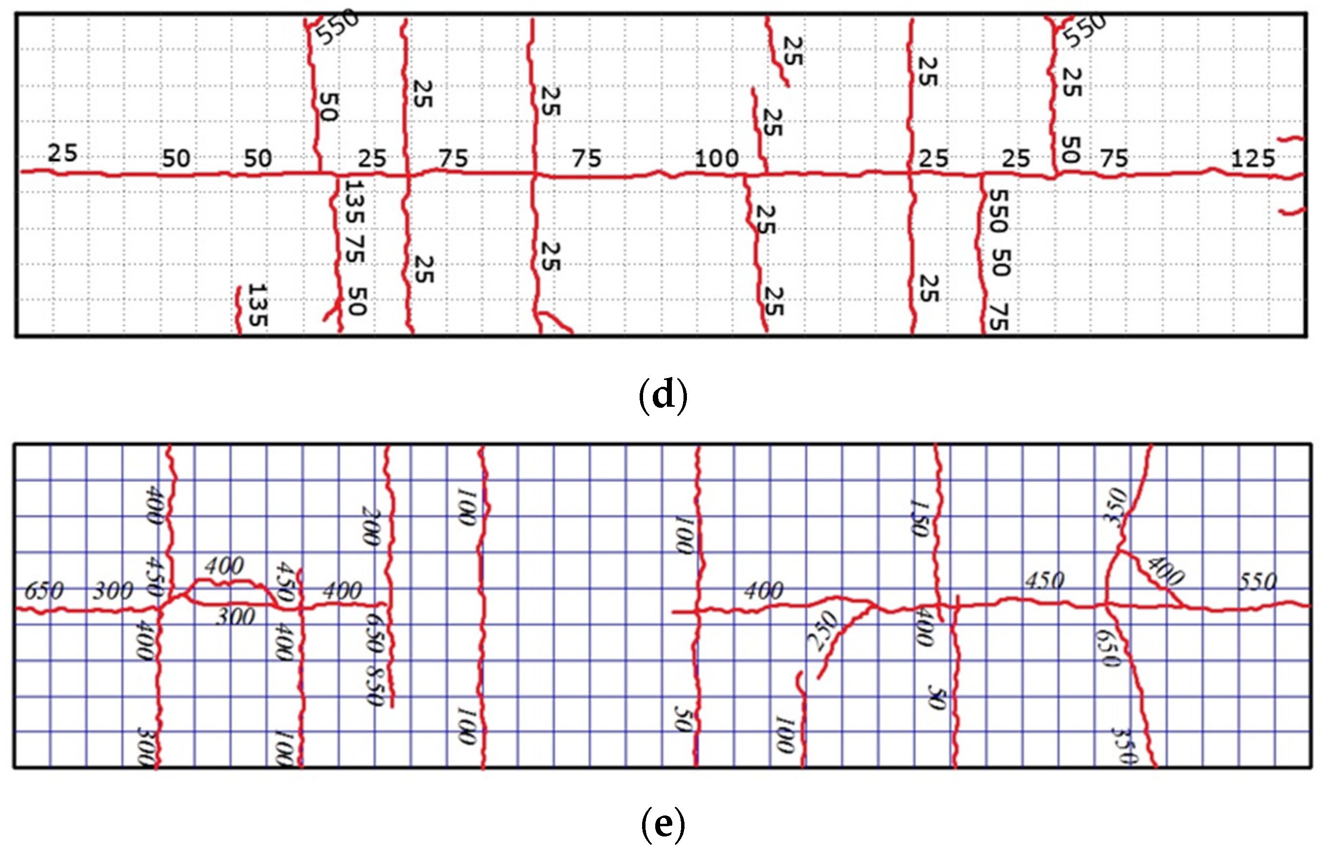
3.1. Crack Distribution and Formation

Observations of the concrete slabs’ external surfaces during fatigue testing revealed fracture initiation and propagation. No developed cracks were expected on the upper surface of the concrete slab under these low-stress conditions, as the neutral axis of the composite section was situated beneath the concrete slab. Minor fractures were, however, detected on the top surface of the concrete slab and the side faces when the number of load cycles increased over 50,000 cycles. As the quantity of load cycles increased, these fissures developed in size and quantity (see Figure 5). The shear span zones were where fatigue cracks were most frequently seen. Cracks in the transverse directions manifested and propagated with increasing the loading cycles in specimens FSB 2 and FSB 3, both featuring complete shear connection. In contrast, cracks in the longitudinal directions emerged and extended amid rows of the headed connectors across the shear span regions in specimen FSB 4. This indicates that the longitudinal fatigue fractures in the concrete slab were significantly influenced by the strength of the shear connection. Moreover, the induced range of shear stress in the headed connectors affected the propagation and distribution of fatigue cracks in the concrete slab. The specimen FSB 5 with the one-row shear connections encountered longitudinal expanding cracks in the concrete slab as a result of concentrations of longitudinal shear stresses, resulting in more extensive damage to the concrete around the headed stud connectors, and these conditions triggered the occurrence of fractures during fatigue loading. While decreasing damage to the concrete slab as well as the occurrence of these longitudinal cracks, these forces were distributed throughout the rows of the headed connectors in the longitudinal directions in specimens FSB 2 and FSB 3.
In the shear span areas of the post-tensioned specimen PFSB 7, longitudinal and transverse fractures developed and spread across the rows of the shear connectors. In addition, more fractures were seen in the fatigued specimens than in the un-strengthened specimens (see Figure 5). This might be explained by the fact that post-tensioning caused early damage and cracks in the longitudinal directions before applying the loading cycles, resulting in a more noticeable spread. The external post-tensioning introduced initial straining actions that were reversed during fatigue loading [10]. The shear connections’ deformations caused by the post-tensioning were reversed during the fatigue loading. Therefore, the longitudinal cracks found solely in the post-tensioned specimen might have been caused by this reversal of stress on the shear connections.

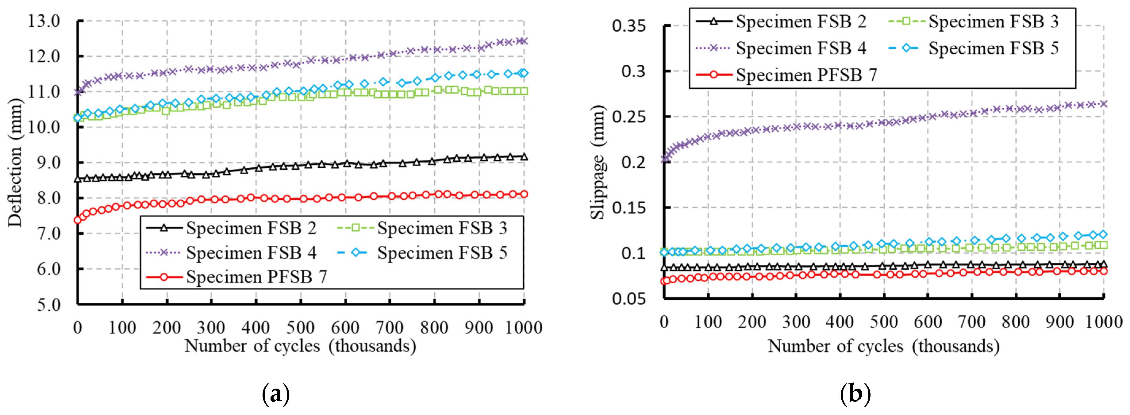
3.2. Cyclic Deformations
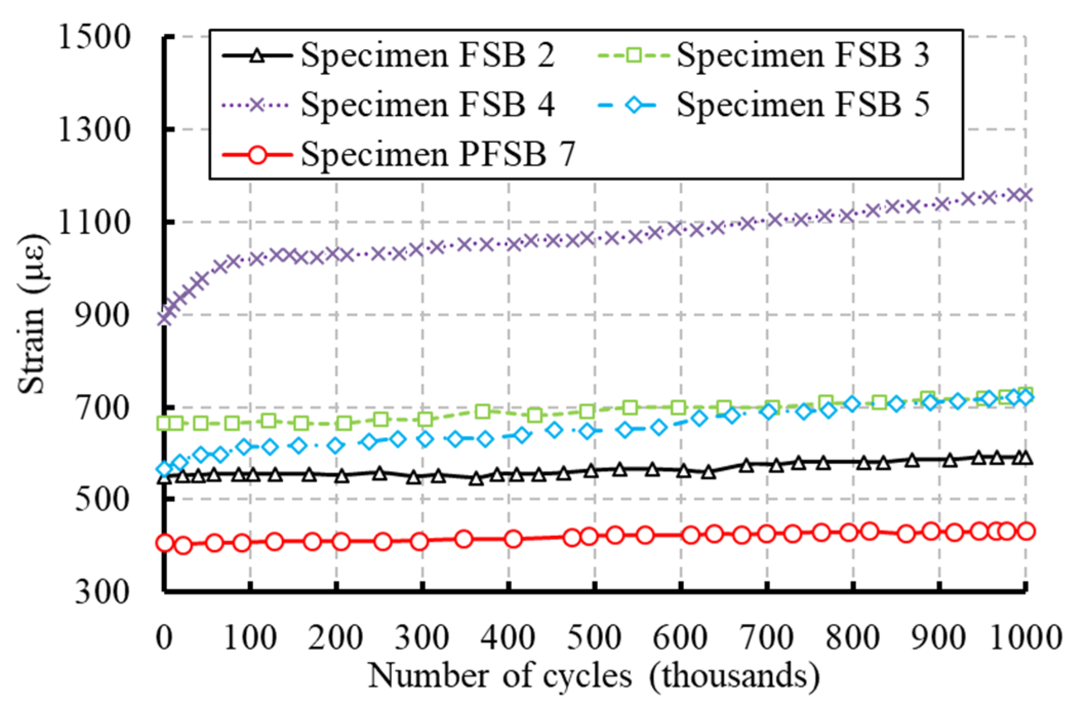
In terms of the cycle load-deflection behavior and the cyclic load-slippage behavior, the cyclic deformations of the fatigued samples are shown in Figure 6. The major causes of the increased residual deformations were the slight spread of the existing cracks and the emergence of new cracks. The shear studs’ damaged area in the concrete slabs produced a loss of stiffness in the connection and an increase in residual deflections as the number of load cycles increased. As the fatigue force range expanded, the residual deflection also grew. Initially, the specimen with partial shear connection showed a quick rise in the remaining mid-span deflection. As opposed to this, specimen FSB 5 showed a larger development in the cyclic deflection after 25% of the cycles (see Figure 6a).
Even while the overall deflection of the reinforced specimen decreased, it quickly increased the residual mid-span deflection in the first 200-or-so cycles of the fatigue test. As can be observed in Figure 6a, the reinforced beam’s maximum upper deflection (8.1 mm) was lower than the un-strengthened specimen’s (9.2 mm). However, the strengthened specimen’s overall rise during the fatigue period (0.74 mm) was larger than the un-stronger specimen’s (0.62 mm), which may be attributed to the strengthened specimen’s enhanced cracking of the concrete slab.
Figure 6b shows the cyclic slippage between the steel and concrete components for the fatigue specimens, with the partial level of shear connection exhibiting the maximum amount of such slippage. The majority of this damage happened during the specimen’s early fatigue life. Moreover, the specimens with full levels of shear connectivity showed identical cyclic slippage. The specimen with the one-row configuration (FSB 5) later exhibited a greater level of cyclic slippage. Despite the fact that the slippage was lower for the post-tensioned specimen (PFSB 7) than the un-strengthened one (FSB 2), the rise in the permanent slippage for PFSB 7 was 3.7 times that for FSB 2.

3.3. Cyclic Strains

The recorded strains in the headed connectors close to supports are depicted in Figure 7. The results show the same behavior, despite the fact that residual deflection (Figure 6a) and plastic slippage (Figure 6b) reveal damage in the level of shear connectivity between the concrete slabs and steel beams. The behavior that coincided shows how well the shear connections and concrete slabs work together. The stresses in the shear connections close to the supports for FSB 4 were quite high (about 50% of the yielding strain), which led to the beginning of a fatigue crack at the shear connectors’ feet. As opposed to the specimen with the two-row configuration (FSB 3), specimen FSB 5 had lower cyclic stresses early in the fatigue testing. At the conclusion of the fatigue testing, the two specimens, however, showed the same degree of stress. Compared to the connections in the two-row configuration, the headed connectors in the one-row design showed incremental stresses that were 152.5% greater. The external PT partially eased the cyclic strain in the shear connections in the reinforced specimen (PFSB 7). In comparison to the specimen without post-tensioning, this 28% reduction in strain can lengthen the lifecycle of the headed connectors for the beam with external post-tensioning.
Figure 8 depicts the cyclic incremental stresses in the bottom flanges of the steel beams alongside the concrete slabs. Throughout the fatigue tests, the cyclic incremental strain consistently elevated due to the progressive accumulation of damage in the connection linking the concrete slab and steel beam. The extent of this damage increased with the fatigue load level, subsequently amplifying the cyclic incremental stresses in both the concrete slabs and steel beams. Notably, in the case of specimen PFSB 7, a fraction of the tensile strain induced by fatigue loading was alleviated by the initial compressive strain generated through the post-tensioning in the steel bottom flange. It is worth noting that maintaining the steel flange at a lower degree of tensile strain can contribute to extending the lifecycle [16].

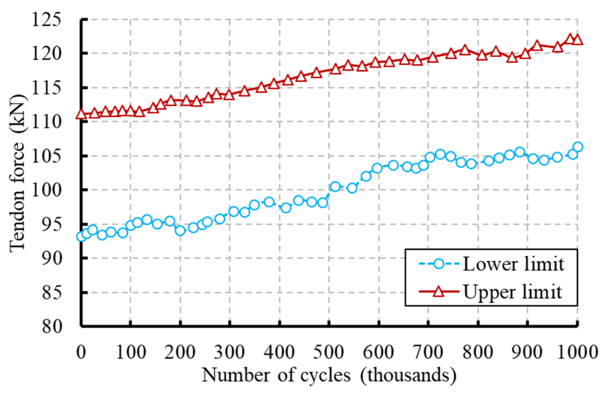
3.4. Cyclic Post-Tensioning Force

The tendons gradually experienced a force increase as a result of the progressive rise in specimen deformation brought on by fatigue (Figure 9). This demonstrated that the tendon did not soften as a result of the repetitive stress. Additionally, it suggested that the end anchors and tendons had a strong grasp on one another. It was adequate to sustain post-tension during the fatigue tests, since the overall increase in the tendons’ force was 10% relative to the initial post-tensioning.

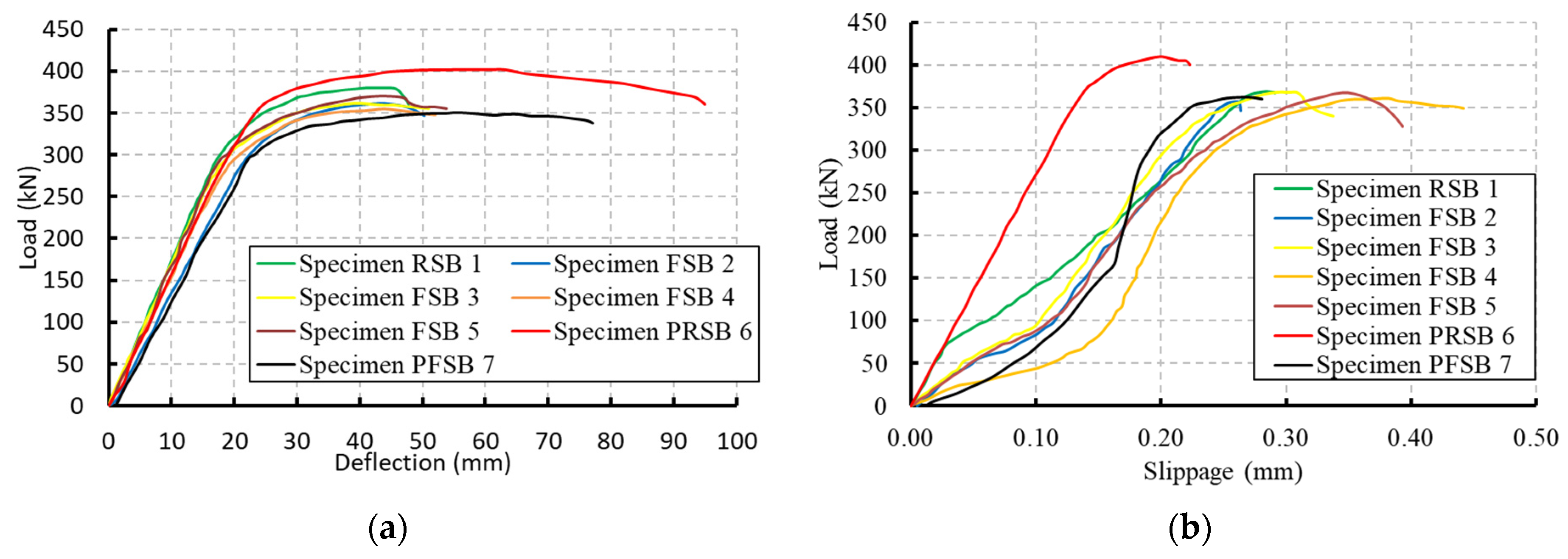
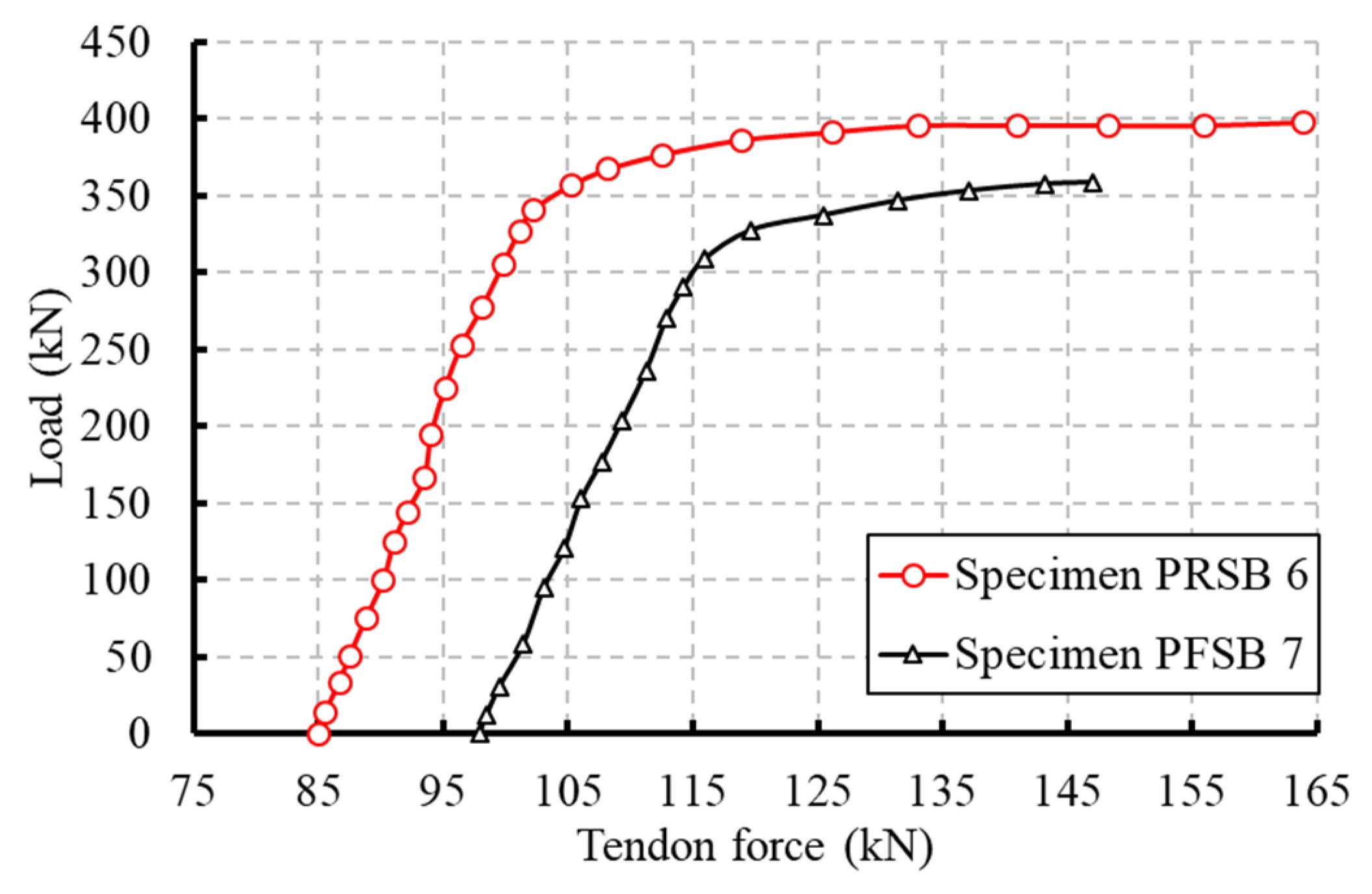
4. Residual Static Behavior

To measure the remaining strength of the tested beams, monotonic tests were conducted up to failure. Additionally, the reference specimens (RSB 1 and PRSB 6) underwent just a static test to compare with the enduring performance of the fatigued samples. The steel beam’s bottom flange’s yielding and the concrete slab’s crushing at the mid-spans were responsible for the detected nonlinear behavior for the control specimens. The static residual strength testing of the fatigued samples revealed the same manner of failure. Measurements of deflection, slippage, strain, and post-tensioning force for the reference and fatigued specimens are compared, and the results are shown in Figure 10, Figure 11 and Figure 12.
According to Figure 10a, all specimens behaved in an elastic manner up to 300 kN, which was linked to the development of non-linear strain in the steel beam’s bottom flange in the center zone (see Figure 11b). The measured strain in the extreme fiber of the concrete slab was very low, below 0.05%, at the start of the steel flange yielding, indicating that the concrete slabs were not damaged at that time (see Figure 11a). As the specimens reached their maximum capacity, the concrete slabs in the center zone began to crumble. The level of shear connectivity was lost as a result of the concrete’s deterioration surrounding the shear connections during fatigue testing. The slippages, which were measured at the loading level of 100 kN, were clear indications of this loss, and are shown in Figure 10b. Figure 10b further demonstrates that once the applied force exceeds the maximum fatigue load of 150 kN, the impact of deterioration surrounding the headed connectors was less severe. The full shear connection prevented the fatigue specimens’ strength from degrading, as shown by Table 4’s change in capacities, despite the fact that the cyclic loads reduced the shear connection between the concrete slab and the steel beam, which decreased the peak loads of the fatigued specimens. Additionally, Figure 10b demonstrates that during the fatigue test, the specimen with the partial level of shear connection sustained higher damage. The patterns for longitudinal slippages for the fatigued specimens with complete shear connection (Figure 10b) after the maximum fatigue load of 150 kN resembled those for the reference specimens. When compared to the reference specimens, the stresses in the concrete slab and steel bottom flange increased, which supported the damage to the shear connection.
Following fatigue loading, the post-tensioning force increased from 46% to 53% of the tendon’s ultimate strength, as illustrated in Figure 12, at the initiation of the residual static testing. This occurred despite a reduction in the strength of the fatigued specimen (PFSB 7). Furthermore, a 10% decline in the maximum post-tensioning force at ultimate strength was observed from the unfatigued specimen (PRSB 6) to the fatigued specimen (PFSB 7).

5. Conclusions

In this paper, experimental findings from fatigue loading tests on composite beams with various arrangements are presented. The fatigue tests were conducted to one million cycles under four-point loading. Additionally, the effects of external post-tensioning and the strength of the shear connection were investigated. Static tests were run until failure to assess the residual behavior. The following conclusions were developed:
  • The longitudinal fatigue shear fractures in the concrete slab were mostly controlled by the degree of the shear connection between the concrete slabs and steel beams. Moreover, the range of shear stress in the headed connectors affected the formation and distribution of fatigue cracks in the concrete slab.
  • By increasing the loading cycles owing to the damaged region that developed in the concrete slab by the headed connectors and which produced a loss of stiffness in the shear connection, an increase in the residual deformations was achieved.
  • The specimen with partial shear connections showed a quick rise in the residual mid-span deflection, and got the greatest enduring deformation in comparison to specimens with the full shear connection.
  • The external post-tensioning greatly reduced the stresses in the shear connections, concrete slab, and steel beam. However, across the shear span areas, fractures in the longitudinal and transverse directions were developed and spread in the concrete slab of the post-tensioned specimen between the rows of the headed connectors.
  • The findings provided in this research show that a larger number of smaller studs with the appropriate shear resistance exhibited more advantageous behavior than a smaller number of larger diameters.
  • While cyclic loads led to a reduction in the shear connection, the intact shear connection successfully averted any deterioration in stiffness and strength for the remaining fatigue specimens.
Conducting additional tests on post-tensioned specimens under increased fatigue cycles is essential for inducing fatigue fractures in headed shear connectors. This will enable a thorough exploration of the fatigue life of these connectors when employed in conjunction with external post-tensioning as a strengthening technique.

Author Contributions

Conceptualization, A.E.-Z. and H.S. (Hesham Shaaban); Formal analysis, H.S. (Hesham Shaaban) and M.T.N.; Investigation, A.E.-Z.; Methodology, H.S. (Hani Salim); Resources, A.E.-Z. and H.S. (Hani Salim); Software, M.T.N.; Supervision, H.S. (Hani Salim) and H.S. (Hesham Shaaban); Visualization, A.E.-Z.; Writing—original draft, H.S. (Hesham Shaaban) and M.T.N.; Writing—review and editing, A.E.-Z. All authors have read and agreed to the published version of the manuscript.

Funding

This research received no external funding.

Data Availability Statement

Data are contained within the article.

Conflicts of Interest

The authors declare no conflicts of interest.

References

  1. Bonopera, M.; Chang, K.C.; Tullini, N. Vibration of prestressed beams: Experimental and finite-element analysis of post–tensioned thin-walled box-girders. J. Constr. Steel Res. 2023, 205, 107854. [Google Scholar] [CrossRef]
  2. Wang, B.; Wang, K.; Liu, X.; Xu, Y. Residual Flexural Capacity of Composite Beams with Corroded Studs after Fatigue. J. Bridge Eng. 2023, 28, 04023026. [Google Scholar] [CrossRef]
  3. Wang, B.; Huang, Q.; Liu, X.; Li, W. Experimental investigation of steel-concrete composite beams with different degrees of shear connection under monotonic and fatigue loads. Adv. Struct. Eng. 2018, 21, 227–240. [Google Scholar] [CrossRef]
  4. Wang, B.; Liu, X.; Zhuge, P. Residual bearing capacity of steel-concrete composite beams under fatigue loading. Struct. Eng. Mech. 2021, 77, 559–569. [Google Scholar] [CrossRef]
  5. Xu, J.; Sun, H.; Chen, W.; Guo, X. Experiment-Based Fatigue Behaviors and Damage Detection Study of Headed Shear Studs in Steel–Concrete Composite Beams. Appl. Sci. 2021, 11, 8297. [Google Scholar] [CrossRef]
  6. Tran, M.-T.; Do, V.N.V.; Nguyen, T.-A. Behaviour of steel-concrete composite beams using bolts as shear connectors. IOP Conf. Ser. Earth Environ. Sci. 2018, 143, 012027. [Google Scholar] [CrossRef]
  7. Lu, K.; Du, L.; Xu, Q.; Yao, Y.; Wang, J. Fatigue performance of stud shear connectors in steel-concrete composite beam with initial damage. Eng. Struct. 2023, 276, 115381. [Google Scholar] [CrossRef]
  8. Kuang, Y.; Wang, Y.; Xiang, P.; Tao, L.; Wang, K.; Fan, F.; Yang, J. Experimental and Theoretical Study on the Fatigue Crack Propagation in Stud Shear Connectors. Materials 2023, 16, 701. [Google Scholar] [CrossRef] [PubMed]
  9. El-Sisi, A.A.; Hassanin, A.I.; Shabaan, H.F.; Elsheikh, A.I. Effect of external post-tensioning on steel–concrete composite beams with partial connection. Eng. Struct. 2021, 247, 113130. [Google Scholar] [CrossRef]
  10. El-Zohairy, A.; Salim, H.; Saucier, A. Steel-Concrete Composite Beams Strengthened with Externally Post-Tensioned Tendons under Fatigue. J. Bridge Eng. 2019, 24, 04019027. [Google Scholar] [CrossRef]
  11. Hassanin, A.I.; Fawzy, H.M.; Elsheikh, A.I. Elsheikh. Fatigue loading characteristic for the composite steel-concrete beams. Frat. Integrità Strutt. 2021, 55, 110–118. [Google Scholar]
  12. El-Zohairy, A.; Salim, H. Parametric study for post-tensioned composite beams with external tendons. Adv. Struct. Eng. 2017, 20, 1433–1450. [Google Scholar] [CrossRef]
  13. El-Zohairy, A.; Salim, H.; Saucier, A. Fatigue tests on steel-concrete composite beams subjected to sagging moments. J. Struct. Eng. 2019, 145, 04019029. [Google Scholar] [CrossRef]
  14. AASHTO. AASHTO LRFD Bridge Design Specifications, 6th ed.; AASHTO: Washington, DC, USA, 2012. [Google Scholar]
  15. ASTM A370; Standard Test Methods and Definitions for Mechanical Testing of Steel Products. ASTM International: West Conshohocken, PA, USA, 2013.
  16. Albrecht, P.; Lenwari, A. Fatigue Strength of Repaired Prestressed Composite Beams. J. Bridge Eng. 2008, 13, 409–417. [Google Scholar] [CrossRef]
Figure 1. Dimensions of the composite specimens (mm). (a) Specimens RSB 1, FSB 2 and FSB 3. (b) Specimen FSB 4. (c) Specimen FSB 5. (d) Specimens PRSB 6 and FPSB 7.
Infrastructures 09 00029 g001aInfrastructures 09 00029 g001b
Figure 2. Post-tensioning system. (a) Schematic layout. (b) On-site photo.
Infrastructures 09 00029 g002
Figure 3. Test setup (mm). (a) Fatigue test. (b) Static test.
Infrastructures 09 00029 g003
Figure 4. Instrumentations. (a) Strain gauges and LVDTs layout. (b) Slippage LVDT and post-tensioning load cells. (c) Shear stud’s strain gauges.
Infrastructures 09 00029 g004
Figure 5. Development and dispersion of fatigue cracks in the concrete slabs (cycle counts are displayed in thousands). (a) Specimen FSB 2. (b) Specimen FSB 3. (c) Specimen FSB 4. (d) Specimen FSB 5. (e) Specimen PFSB 7.
Infrastructures 09 00029 g005aInfrastructures 09 00029 g005b
Figure 6. Cyclic deformations. (a) Cyclic deflection. (b) Cyclic slippage.
Infrastructures 09 00029 g006
Figure 7. Cyclic strains in the shear connectors.
Infrastructures 09 00029 g007
Figure 8. Cyclic strains in the concrete slabs and steel beams. (a) Concrete slab. (b) Steel beam.
Infrastructures 09 00029 g008
Figure 9. Fatigue variations in the post-tensioning force.
Infrastructures 09 00029 g009
Figure 10. Static residual deformations. (a) Residual deflection. (b) Residual slippage.
Infrastructures 09 00029 g010
Figure 11. Static residual strains in the extreme fibers of the composite sections. (a) Concrete slab. (b) Steel beam.
Infrastructures 09 00029 g011
Figure 12. Static residual post-tensioning force.
Infrastructures 09 00029 g012
Table 1. Spacing of the steel reinforcement and shear studs.
SpecimenComposite LevelDiameter (mm)No. of RowsSpacing of Shear Connectors (mm)Spacing of Steel Rebars
(mm)
LongitudinalTransverseLongitudinalTransverse
RSB 1Full (1.0)15.9Two122.263.5215.9122.2
FSB 2Full (1.0)15.9Two122.263.5215.9122.2
FSB 3Full (1.0)15.9Two122.263.5215.9122.2
FSB 4Partial (0.6)15.9Two209.563.5215.9104.8
FSB 5Full (1.0)22.2One112.7-215.9113.0
PRSB 6Full (1.0)15.9Two122.263.5215.9122.2
PFSB 7Full (1.0)15.9Two122.263.5215.9122.2
R: Reference, F: Fatigue, S: Static, P: Post-tensioning, and B: Beam.
Table 2. An overview of the fatigue loadings.
SpecimenLevel of Shear ConnectivityFatigue Load (kN)Shear Stress Range
(MPa)
No. of Cycles (103)
Upper LimitLower LimitRange
RSB 11.0-----
FSB 21.0160.113.3146.877.01000
FSB 31.0177.913.3164.687.41000
FSB 40.6160.113.3146.8132.21000
FSB 51.0177.913.3164.681.31000
PRSB 61.0-----
PFSB 71.0160.113.3146.877.01000
Table 3. Material characteristics.
Steel RebarsConcreteSteel Beam Headed Studs
fy
(MPa)
fu
(MPa)
E
(GPa)
fc′
(MPa)
fy
(MPa)
fu
(MPa)
E
(GPa)
fy
(MPa)
fu
(MPa)
E
(GPa)
294.2402.5207.832.4345450204351.6448.2206.5
Table 4. Residual static results.
SpecimenLevel of Shear ConnectivityPeak LoadYielding LoadSlippage
kN% ChangekN% Changemm% Change
RSB 1Full378.7----295.2----0.06----
FSB 2Full363.8−3.9285.9−3.20.10+66.7
FSB 3Full361.9−4.4277.3−6.10.11+83.3
FSB 4Partial355.4−6.2240.6−18.50.16+166.7
FSB 5Full370.0−2.6299.0−1.60.11+83.0
PRSB 6Full402.3----341.0----0.04----
PFSB 7Full350.8−12.8300.0−12.00.13+225.0
Disclaimer/Publisher’s Note: The statements, opinions and data contained in all publications are solely those of the individual author(s) and contributor(s) and not of MDPI and/or the editor(s). MDPI and/or the editor(s) disclaim responsibility for any injury to people or property resulting from any ideas, methods, instructions or products referred to in the content.

