Article

Strength and Deformation of Concrete-Encased Grouting-Filled Steel Tubes Columns Exposed to Monotonic Quasi-Static Loading Conditions

1
Department of Civil Engineering, University of Baghdad, Baghdad 17001, Iraq
2
L2MGC, CY Cergy-Paris University, 95031 Neuville-sur-Oise, France
*
Author to whom correspondence should be addressed.
Infrastructures 2024, 9(2), 26; https://doi.org/10.3390/infrastructures9020026
Submission received: 3 January 2024 / Revised: 26 January 2024 / Accepted: 30 January 2024 / Published: 1 February 2024

Abstract

:
This study aimed to evaluate the effectiveness of a novel concrete-encased column (CE) using small circular steel tubes filled with cementitious grouting material (GFST) as the primary reinforcement instead of traditional steel bars. The research involved three different types of reinforcement: conventional steel bars, concrete-filled steel tubes with 30% of the reinforcement ratio of steel bars, and concrete-filled steel tubes with the same reinforcement ratio as steel bars. Twenty-four circular concrete columns were tested and categorized into six groups based on the type of reinforcement employed. Each group comprised four columns, with one subjected to concentric axial load, two subjected to eccentric axial load (with eccentricities of 25 mm and 50 mm, respectively), and one tested under lateral flexural loads. To validate the experimental results, finite element (FE) analysis was conducted using ABAQUS software version 6.14. The experimental findings for concentric load reveal that columns with the second type of reinforcement, concrete-filled steel tubes with 30% of the reinforcement ratio of steel bars exhibited a failure load 19% lower than those with steel bars, while columns with the third type of reinforcement, concrete-filled steel tubes with the same reinforcement ratio as steel bars achieved a failure load 17% greater than the traditional steel bars. The FE analysis demonstrates good agreement with the experimental outcomes in terms of ultimate strength, deformation, and failure modes.

1. Introduction

Modern structures frequently incorporate steel and reinforced concrete to create composite elements due to their superior properties. CE-CFST columns are a form of composite column used in tall, long-span buildings in high earthquake-prone areas. They are composed of concrete-enclosed concrete-filled steel tubes [1,2]. These composite columns consist of CFST encased in reinforced concrete (RC). CFST is used in this type of composite column because of its high strength, durability, and ductility due to the composite action [3,4,5].
Comparing the CE-CFST column to traditional reinforced concrete columns reveals improved mechanical characteristics like strength, stiffness, durability, and fire resistance [6]. CE-CFST columns also improve the resistance to buckling since the columns of tall and long-span buildings are usually subjected to imperfections [7]. CE-CFST columns can be made with square or circular steel tubes encased in square or circular RC cross-sections (Figure 1) [8]. Square RC columns and circular steel tubes enhance building structural integrity. Circular RC–circular CFST composite is preferred for bridge piers due to better confinement provided by circular stirrups, resulting in higher strength and ductility [9,10,11].
Numerous studies investigated the performance of box CE-CFST columns under eccentric axial load, focusing on parameters like height-to-width ratio and load eccentricity. Results show higher ultimate strength, stiffness, and ductility of box CE-CFST columns compared to RC columns with a high eccentric ratio [12,13].
Han and An [14] developed a finite element analysis model to investigate the response of concrete-encased CFST box columns under compression using different material models. The study considered various parameters such as concrete and steel strength, steel tube ratio, steel bar ratio, and stirrup spacing to evaluate their impact on the ultimate load. The results reveal that the ultimate load increase and ductility decrease as the strength of concrete increases. Increases in ultimate load were shown with an increased steel bar and steel tube reinforcement ratio. No change in ductility was observed with an increase in the steel bar ratio, whereas the ductility increased as the steel tube ratio increased. A simplified formula is proposed for predicting the ultimate load of the CE-CFST columns under compression load.
Two parameters were considered in the experiments and numerical analysis of CE-CFST columns [15]: Steel tube-to-column diameter ratio (Di/Do) and concrete strength. The results indicate that the maximum strength of CE-CFST columns was slightly lower than that of reference columns. However, the ductility of the CE-CFST specimens showed a slight enhancement compared to the RC specimens. The maximum compressive strength increased with the increase in the Di/Do ratio and the compressive strength of concrete. Conversely, the ductility decreased as the strength of the concrete increased.
Hadi et al. [16] and Alhussainy et al. [17] conducted experiments on self-compacting concrete columns reinforced with small steel tubes instead of traditional reinforcing bars. The results show that steel tubes have comparable ultimate strength to traditional columns and higher ductility when exposed to concentric loading. The study also found that specimens reinforced with a high slenderness ratio experienced a greater decrease in ultimate load when the spiral pitch increased from 50 to 75 mm.
CFST encased in engineered cementitious composite (ECC) columns were tested with varying parameters, including longitudinal and transverse reinforcement ratios, steel tube thickness, and eccentricity ratio [18,19]. The ECC–CFST composite column showed superior strength and ductility under different eccentricities, with compression, balanced, and tension failure modes observed. Enhancement in ultimate strength and ductility can be achieved by increasing longitudinal reinforcement and steel tube thickness. Chen et al. [20] studied the behavior of the CE-CFST box column, a composite CFST element surrounded by a reinforced concrete column. They found that larger diameter steel tubes improved ductility and strength. A simplified model was presented to predict the initial stiffness and maximum strength of CE-CFST box stub columns under concentric load. The mechanical behavior of enclosed CFST columns with engineered cementitious composite (ECC) and reinforced concrete component (RCC) under various eccentric loading scenarios was investigated using a finite element analysis (FEA) [21]. The ultimate strength of CFST columns encased with ECC was better than that of CFST columns encased with RC under different eccentric loads. Additionally, as the eccentricity of the applied load increased, the ultimate strength decreased.
Research under eccentric and concentric compression loads was carried out on CE-CFST columns with thin concrete encasement and high-strength circular steel tubes [22]. The usage of concrete encasement and tie spacing were the main topics of the investigation. The results demonstrate that decreasing the perimeter tie spacing postponed the crushing of the concrete encasement and marginally raised the peak strength. Furthermore, the outcomes demonstrate that the stiffness was more significantly affected by the concrete encasement than by the concrete’s strength inside the steel tube.
ABAQUS software was used to perform FE analysis for the response of CFST encased in ECC under eccentric loads Parametric analysis reveals that the eccentricity ratio significantly influences the composite column’s failure process, with the confinement effect decreasing as the ratio increases. The ultimate strength of the ECC-encased CFST column is also influenced by the steel tube strength, steel tube ratio, and longitudinal reinforcement ratio [23]. Hameed et al. [24] conducted a study to analyze the performance of reinforced concrete columns involving steel tubes placed at the cross-sectional center of the column. The study examined the effects of varying steel tube diameters and eccentric loads. The study’s findings indicate that the employment of steel-embedded tubes resulted in enhanced performance of eccentric columns, namely, strength and ductility.
A review of the literature indicated above reveals that very few studies have looked at the behavior of concrete that has been reinforced using small steel tubes rather than steel bars in terms of strength, deformation, and analytical methods. Thus, more investigation is required using other factors in order to completely comprehend the behavior of these kinds of columns.
As indicated earlier, instead of conventional steel bars, a novel kind of concrete-encased (CE) column has been developed, employing tiny circular steel tubes filled with cementitious grouting material (GFST) as longitudinal reinforcement. However, little is known about how these kinds of composite columns behave. The objective of this research is to investigate the behavior of concrete-encased grout-filled tubes (CE-GFST) under various loading conditions. Specifically, the study will concentrate on the effects of spiral pitch and main reinforcement form on ultimate strength, deformation, and failure mode. It also aims to create interaction diagrams for these structural elements, marking one of the earliest technical studies to establish the feasibility of using steel tubes for reinforcing concrete columns.

2. Experimental Program

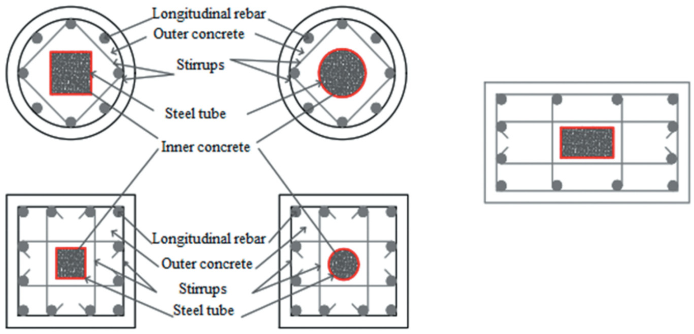
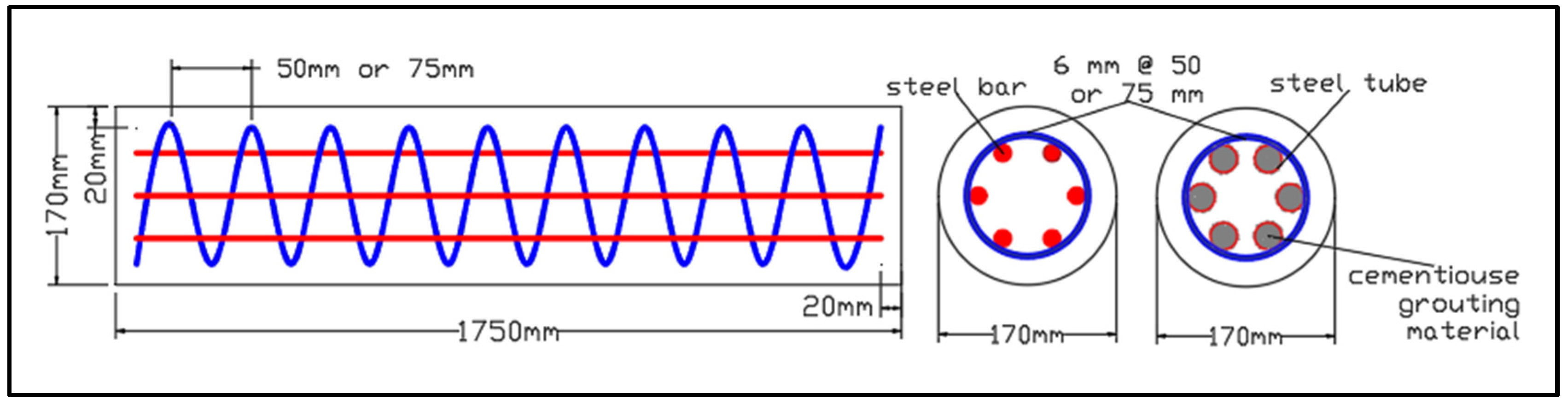
2.1. Test Matrix Specifications

A total of twenty-four circular reinforced concrete columns of mid-scale size were fabricated, cast, and tested under concentric, eccentric, and flexural loading. These specimens were categorized into six groups based on the type of longitudinal reinforcement that was used. The first and second groups, referred to as reference groups, were reinforced with Ø 16 m m -diameter deformed steel bars. To reinforce the third and fourth groups, cementitious-grouting-material-filled steel tubes with an outside diameter of 16 mm were used. For these groups, the longitudinal reinforcement ratio for steel tubes is only 30% of the reinforcement ratio of steel bars used in the first and second groups. The remaining groups were reinforced with cementitious-grouting-material-filled steel tubes with an outside diameter of 25.4 mm, where the longitudinal reinforcement ratio for steel tubes is equivalent to the reinforcement ratio of steel bars used in the first and second groups. Each group consists of four columns. The first column was exposed to concentric axial load; the second and third columns were exposed to eccentric axial load with two different eccentricity values of 25 mm and 50 mm, respectively. Finally, the fourth column underwent testing as a beam subjected to lateral flexural load. These columns had identical reinforcement, including six longitudinal steel bars or tubes uniformly distributed around the perimeter. Spiral transfer reinforcement with a diameter of 6 mm was used with a spiral pitch of either 50 mm or 75 mm. The tested specimens’ dimensions were selected to align with the capabilities and parameters of the laboratory’s testing facilities. The dimensions of all specimens are 1750 mm in height and 170 mm in diameter. They are classified as long columns according to ACI318-19 code limitation (Section 6.5.2.1. (b)) [25]. Highly flowable cementitious grouting materials were utilized to fill small circular steel tubes without any segregation. The tubes were filled with this material before being installed in the column specimens. To prevent the plain steel tube from slipping into the concrete, a combination of epoxy and sand was used to roughen its surface, with epoxy resin applied as an adhesive for this purpose. A paintbrush was used to apply the coating to the surface of each steel tube. The column specimen dimensions, reinforcement, and test matrix used in this study are displayed in Figure 2 and Table 1.

2.2. Materials Properties

The study involved producing normal-strength concrete for casting the tested specimens, while small circular steel tubes were infilled using high-strength cementitious grouting material. The grouting material was treated as concrete to establish the hardened properties. To estimate the compressive strength, splitting tensile strength, rupture modulus, and elasticity modulus of concrete, several standard specimens were tested according to the respective ASTM standards: ASTM C39/C39M [26], ASTM C496/C496M [27], ASTM C78 [28], and ASTM C469 [29], respectively. The hardened properties of concrete have been summarized in Table 2. Three specimens with a length of 500 mm from each steel bar and three coupons from each steel tube were tested according to ASTM A615/A615M [30] and ASTM A370 [31], respectively. The results of the tested steel bar and steel tube reinforcement are presented in Table 3.

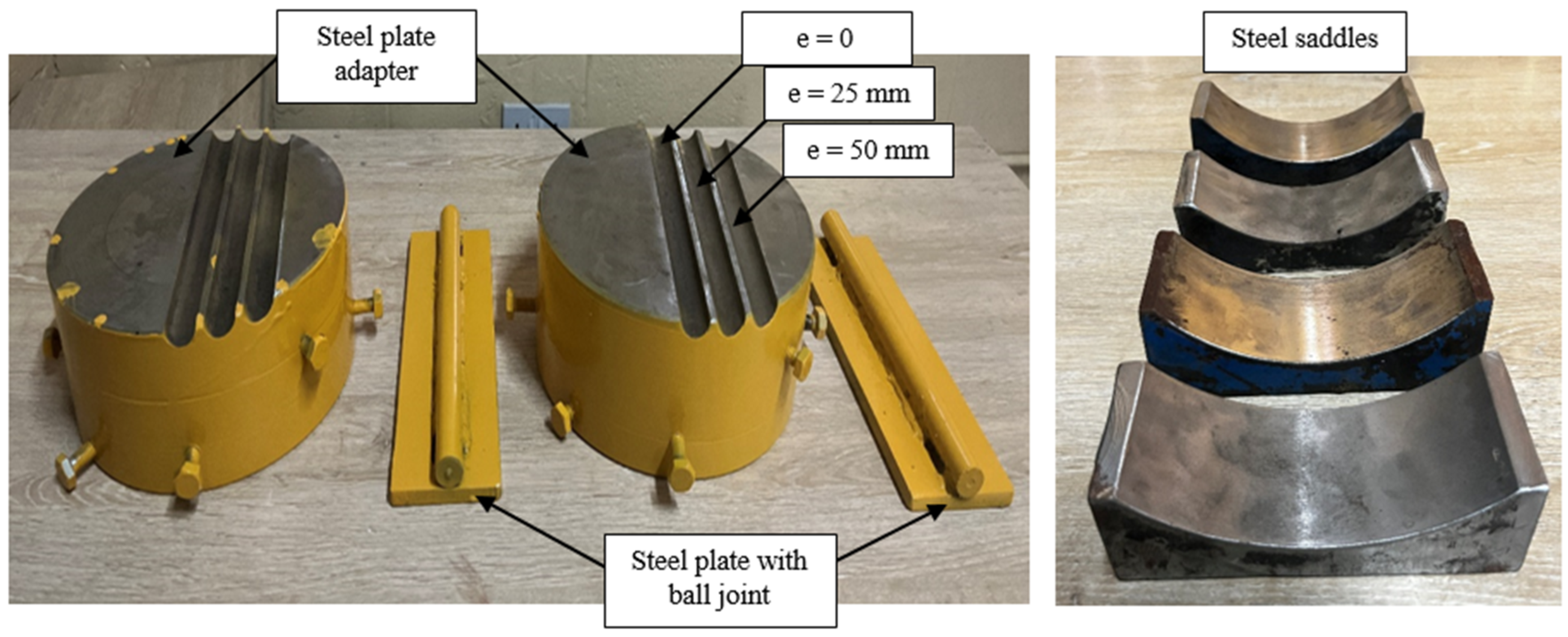
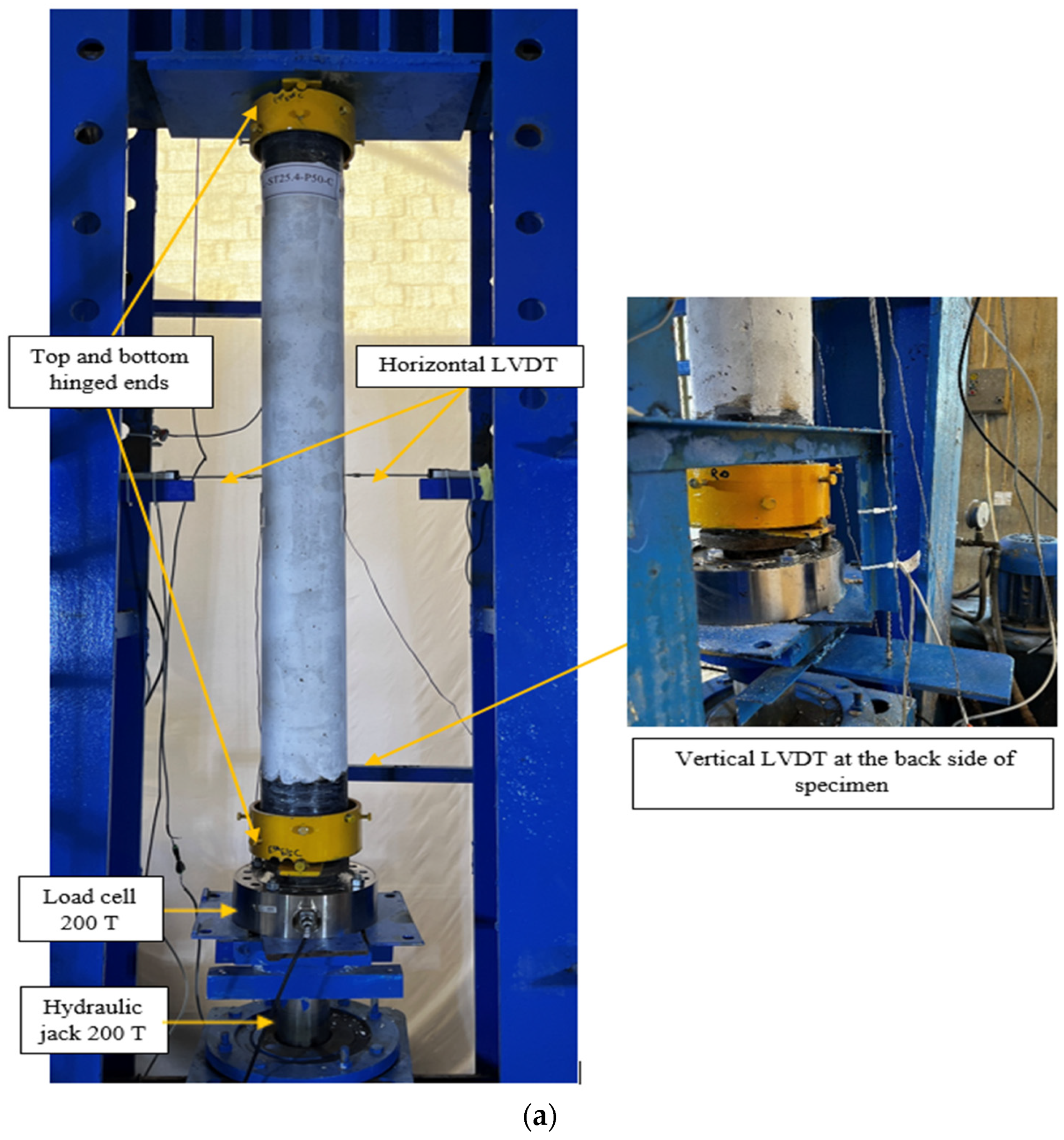
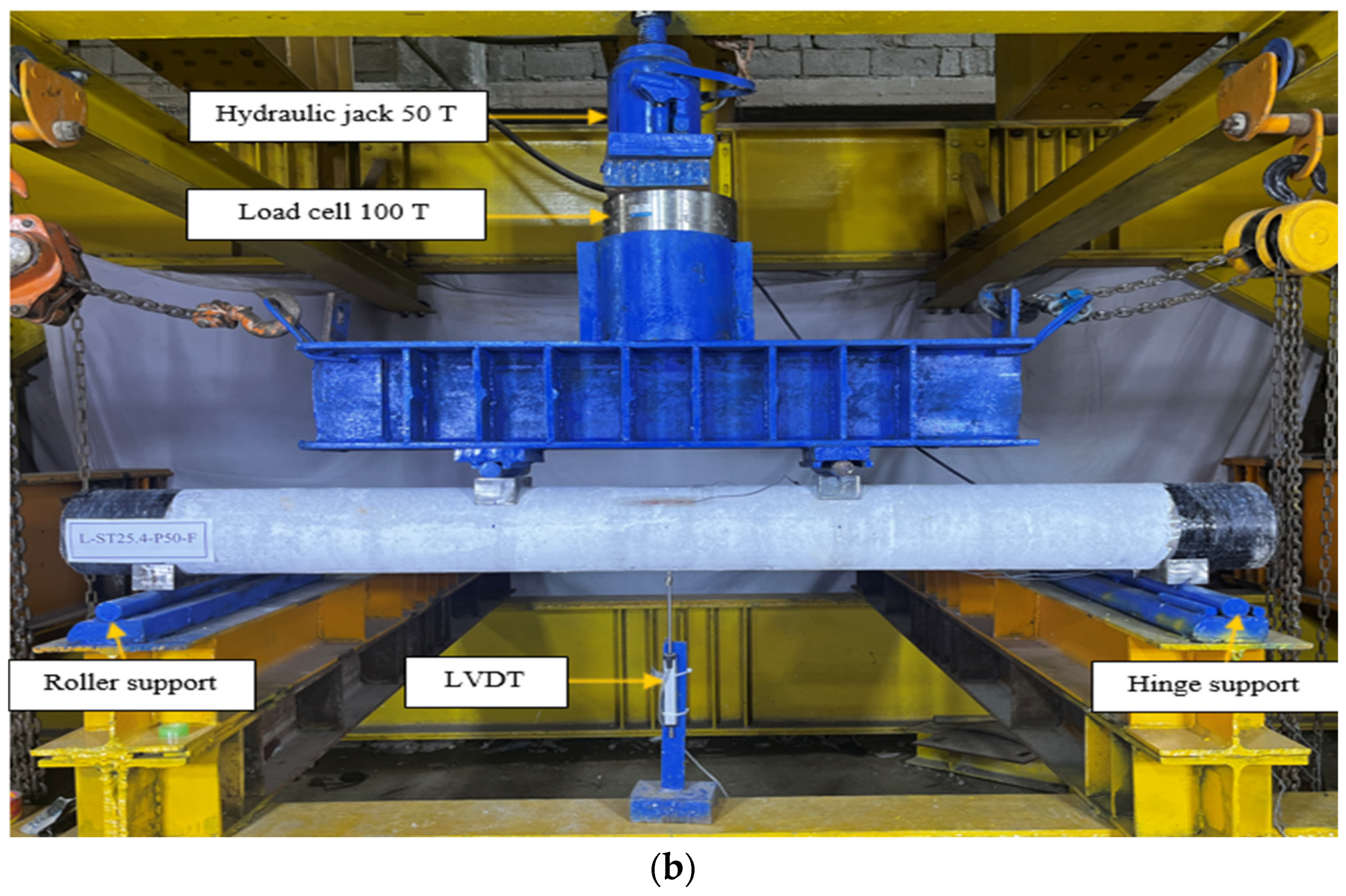
2.3. Setup Details of Tested Specimens

The experimental investigation involved testing columns with hinged connections at both ends, using two loading heads for concentric and eccentric loads. Four steel saddles were manufactured to test a circular column as a beam, creating a simple supported scheme (Figure 3). A hydraulic universal rig with a maximum capacity of 200 tons was used in the column test. This rig was utilized to apply a monotonically increasing load on the column specimens. To prevent local crushing, a 150 mm wide CFRP sheet was used to strengthen column specimen ends, while a 200-ton capacity load cell was installed between the loading head and hydraulic jack for accurate specimen load measurement. Two strain gauges were used to measure axial strain on longitudinal reinforcement sides of steel bars or tubes, with linear variable differential transformers (LVDT) used to record axial and lateral deformation (Figure 4a). The circular column was tested under two-point loading using a 50-ton hydraulic jack and a 100-ton load cell, with deflection at mid-span measured using a single LVDT, as shown in Figure 4b. The load and deformation data were automatically obtained using a computer system.

3. Numerical Part of the Study

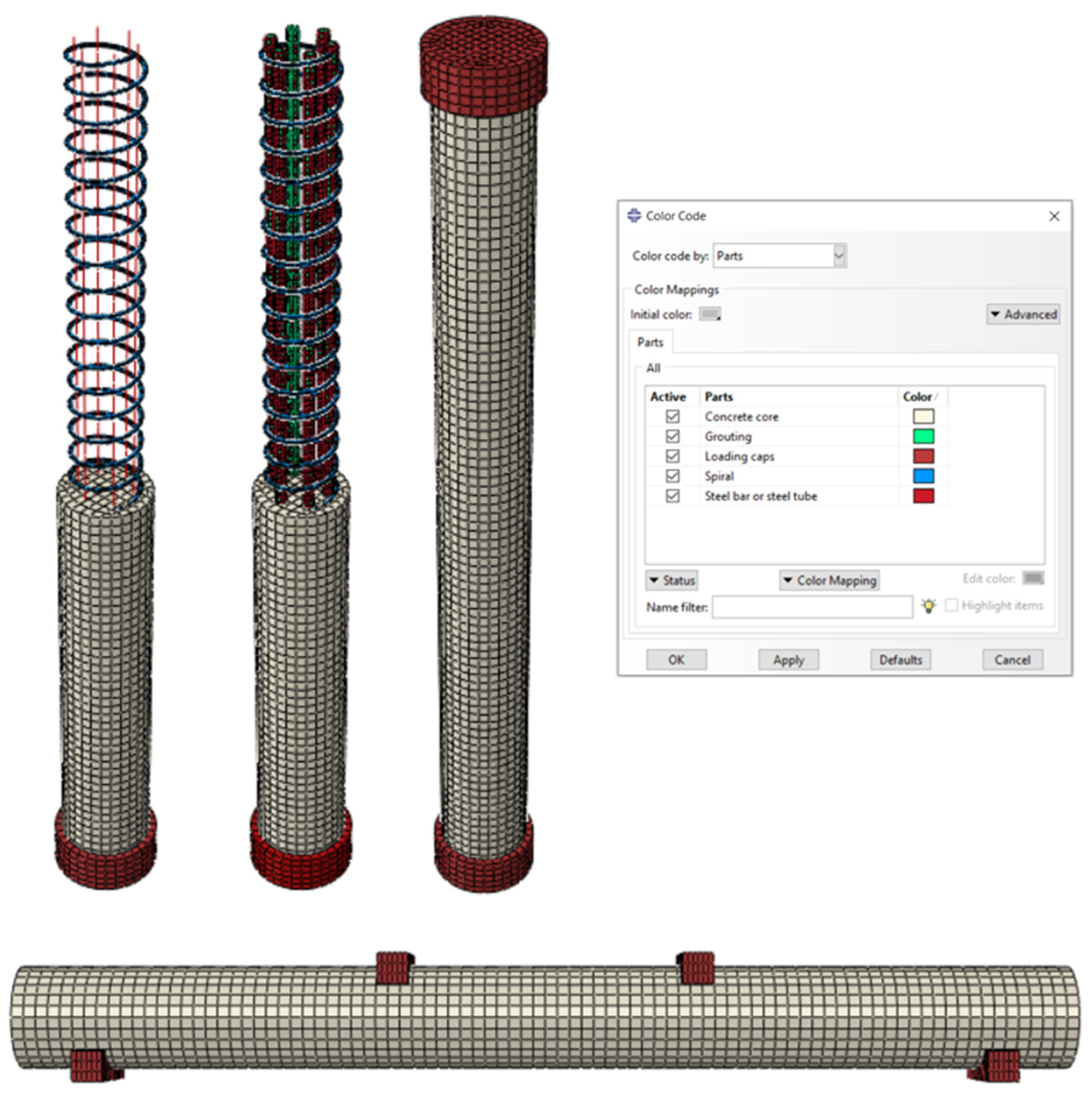
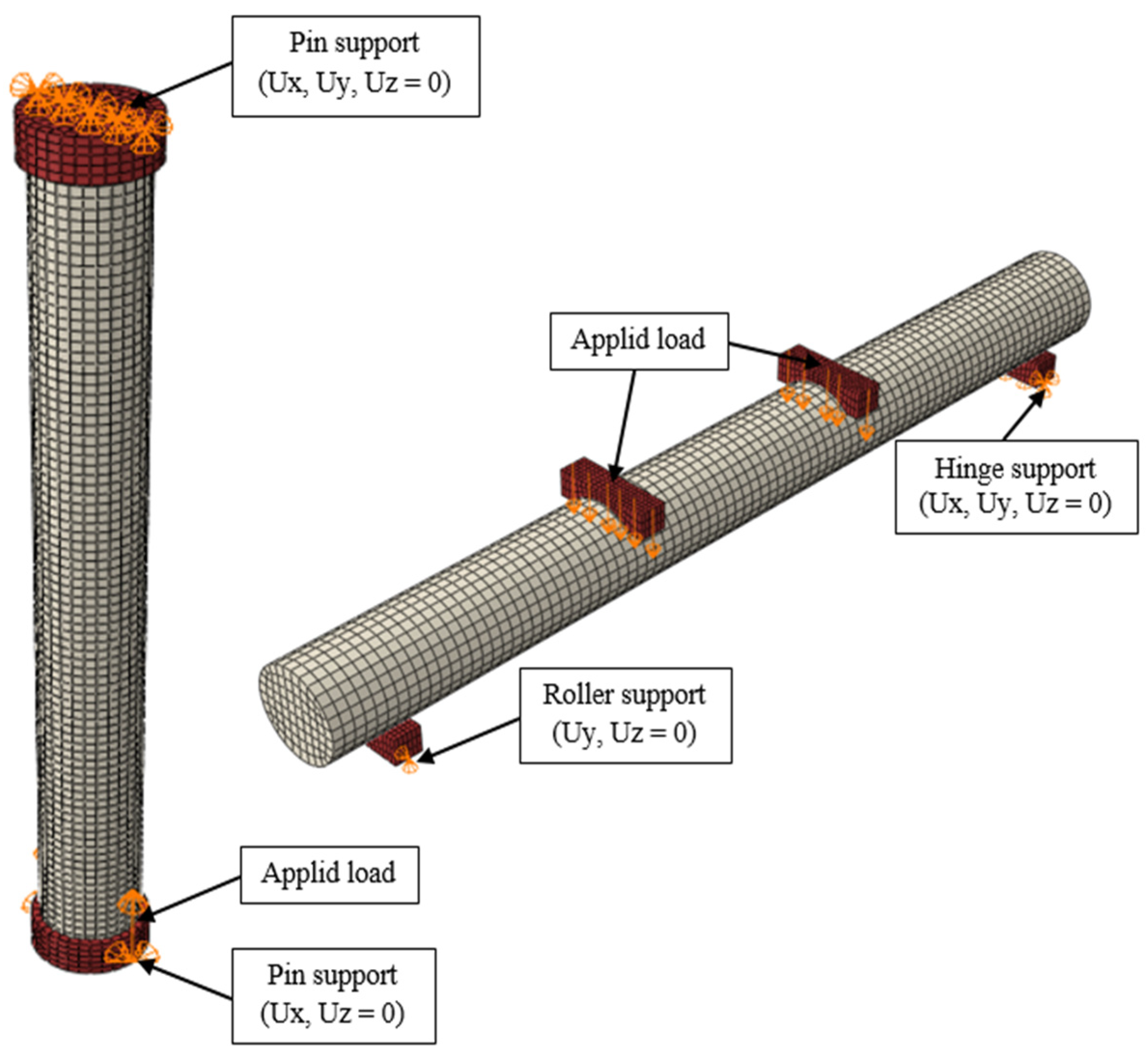
3.1. FE Modeling and Boundary Conditions

This study used ABAQUS software [32] to model the CE-GFST columns. ABAQUS uses two analysis methods: linear buckle and nonlinear Riks analysis, which were used to analyze a slender column. Buckling analysis assesses structure susceptibility to imperfections, generating node coordinates for mode shapes. Riks analysis introduces imperfections for a smooth transition into the post-buckling region and overcomes bifurcation problems. Riks is used for predicting unstable collapses, following an eigenvalue buckling analysis, and involves editing model keywords to introduce imperfections.
The study modeled concrete, cementitious grouting material, steel loading caps, and steel saddle plate using solid C3D8R elements with a 20 mm mesh size. The longitudinal steel bar was modeled using a T3D2 element with a 40 mm mesh size, while the transverse steel bar was modeled using a C3D8R element with a 20 mm mesh size. The steel tube was modeled using shell elements S4R with a 20 mm mesh size (Figure 5). To find the trustworthy mesh size, a numerical example was tried. Using appropriate convergence criteria, this size was selected to closely match the experimental results.
The study tested a hinged column with steel loading caps to meet boundary conditions and applied load. The upper end was constrained in all directions, while the lower end was restricted in movement except for axial deformation. The column was tested as a simply supported beam with steel saddle plates, using displacement control for load application. The FE boundary conditions and the applied load are depicted in Figure 6.

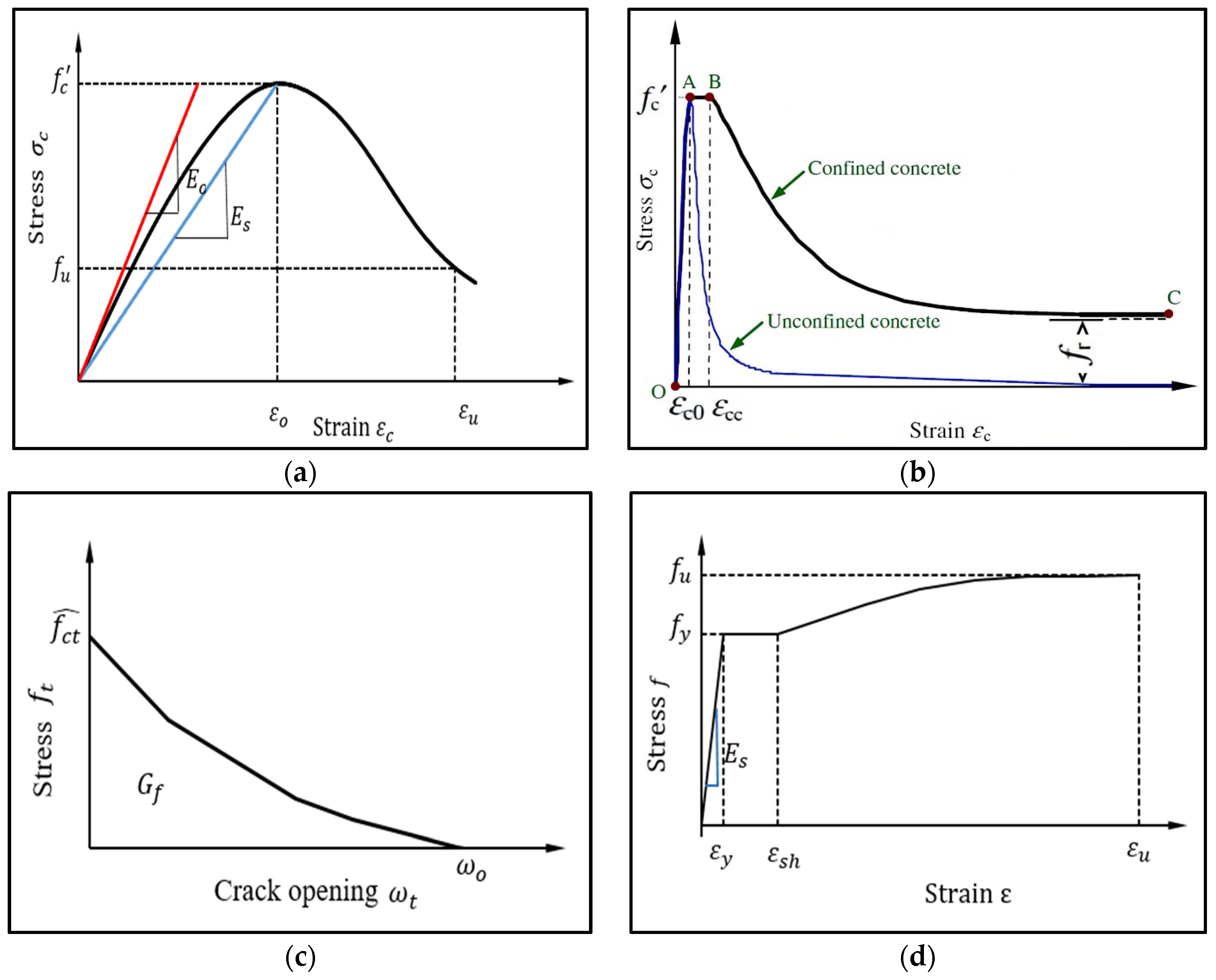
3.2. Modeling of Materials

The nonlinear behavior of concrete and grouting material was considered using the concrete-damaged plasticity CDP model in the software [33]. The CDP model depicts the mechanisms of crushing and cracking failure that occur in concrete. This study adopted the Saenz stress–strain compression model for concrete (Figure 7a) [34]. A CFST stress–strain model was employed to simulate the cementitious grouting material inside the steel tubes. The model adopted by Tao et al. [35] was used to model the cementitious grouting material in compression, as illustrated in Figure 7b. The tension softening of concrete and grouting material was modeled using the Hordijk model [36]; see Figure 7c.
Five crucial parameters must be included in the CDP model. In this study, dilation angle (ψ), eccentricity (ε), the ratio between the biaxial compressive stress and uniaxial compression stress of concrete ( f b o / f c o ), the ratio of the second invariant on the tensile meridian (Κc), and the viscoplastic regularization parameter (μ) were all set at 36, 0.1, 1.16, 0.667, and 0, respectively. Longitudinal, transverse steel bars and loading caps are modeled as elastic-perfect plastic. Figure 7d shows the stress–strain model used to model the steel tube [37].

4. Test Results and Finite Element Validation

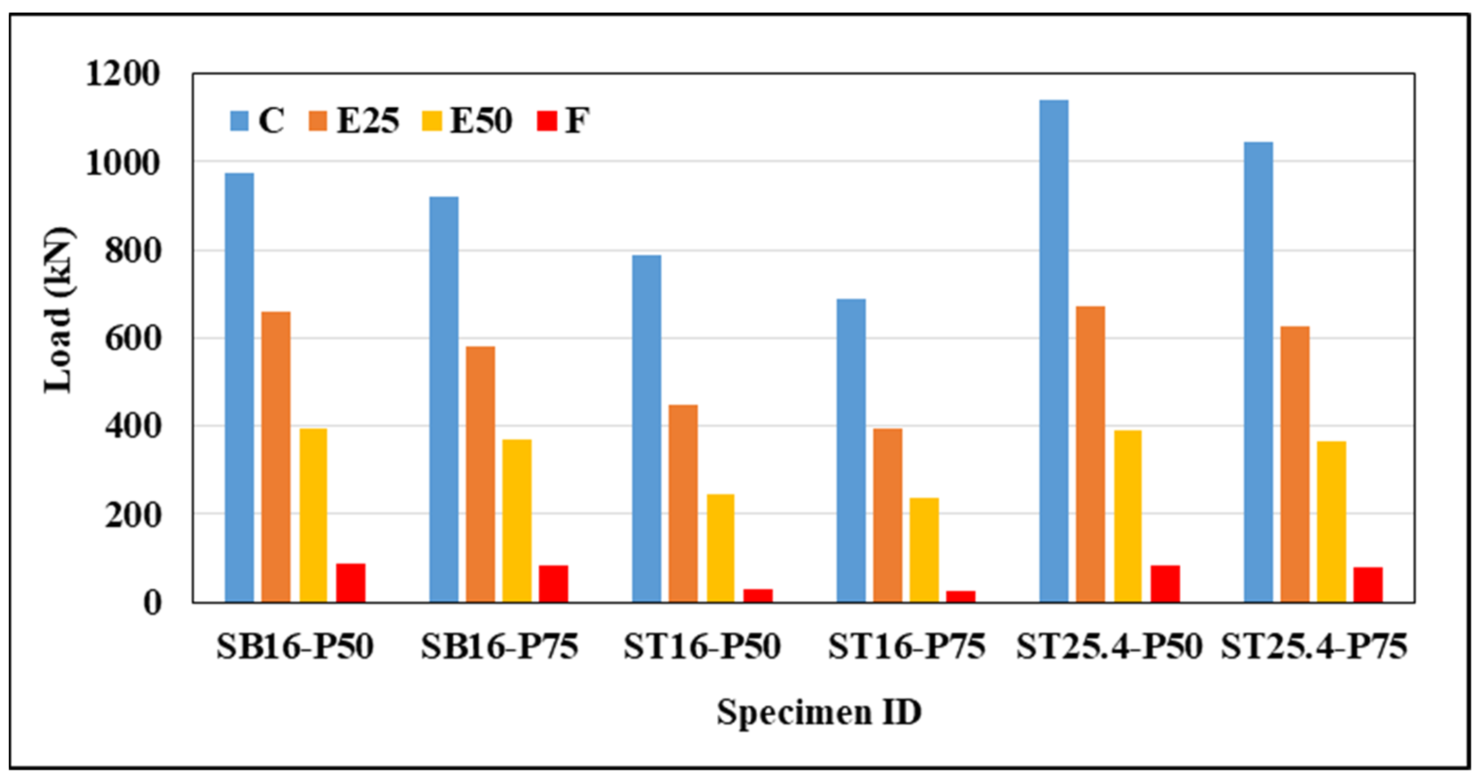
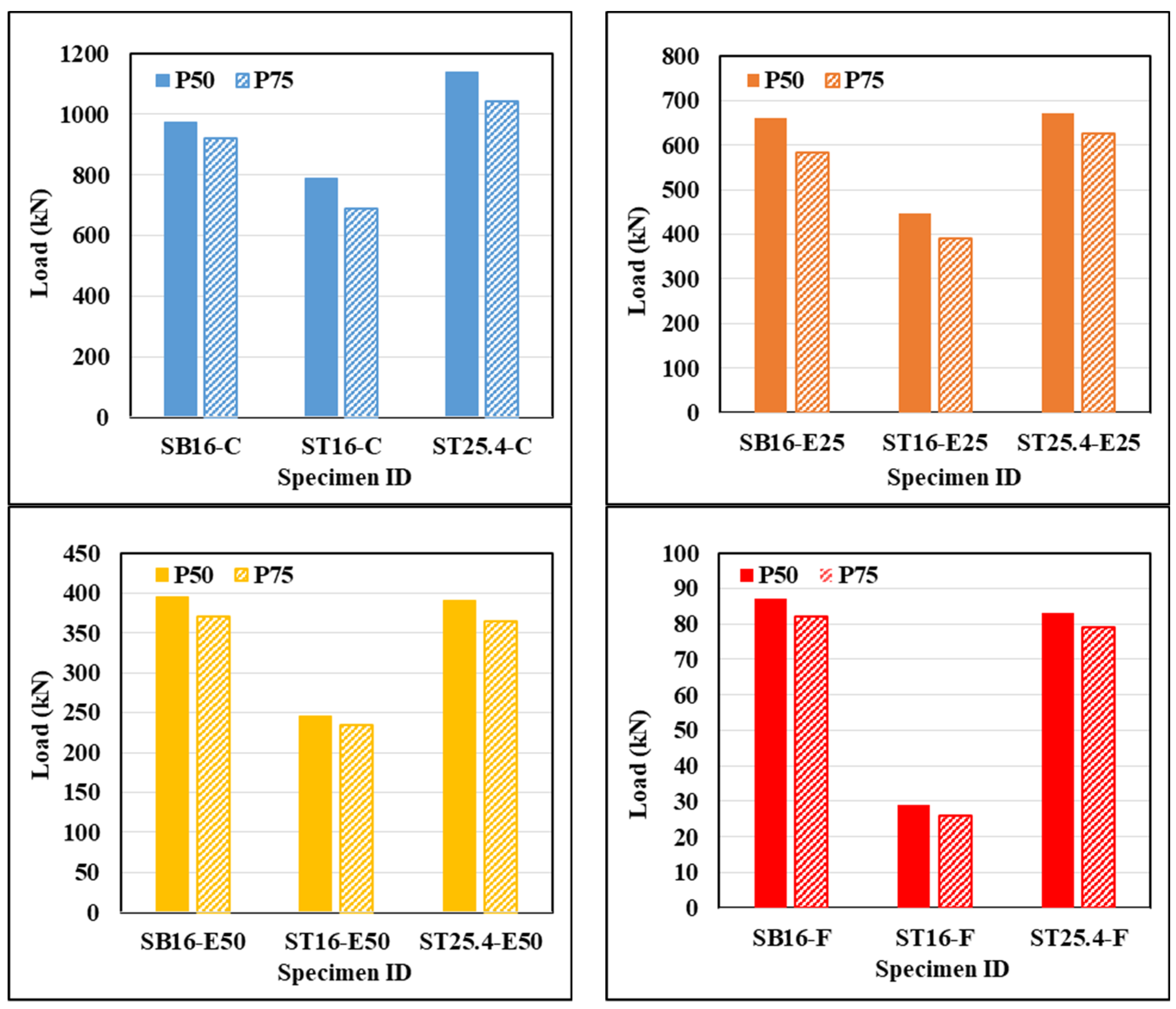
4.1. Load Capacity of CE-GFSTs Columns

The effect of longitudinal reinforcement type and spiral pitch on the ultimate strength of RC columns under several loading conditions are listed in Table 4. The second type of concrete column reinforcement uses 16 mm outer diameter steel tubes representing 30% of the reinforcement ratio of steel bars of 16 mm diameter; the concentric tested specimens ST16-P50-C and ST16-P75-C achieved 81% and 75% ultimate strength, respectively. Under compression loads of 25- and 50-mm eccentricity, specimens ST16-P50-E25, ST16-P75-E25, ST16-P50-E50, and ST16-P75-E50 achieved 68, 67, 62, and 63% ultimate strength, respectively. In flexural loading tests, specimens ST16-P50-F and ST16-P75-F reached 34% and 32% ultimate strength.
For the third type of concrete column reinforcement, the specimens ST25.4-P50-C and ST25.4-P75-C tested under concentric compression load achieved an ultimate strength of 17% and 13% higher than the ultimate strength of the reference specimens. It can be also observed that for a 25-mm eccentric compression load, the ultimate strength of the specimens ST25.4-P50-E25 and ST25.4-P75-E25 is slightly higher than those reinforced with steel bars. The increases in ultimate strength are 2% and 5% compared with reference specimens, respectively. Additionally, the tested results reveal a decrease in the ultimate strength of the identical specimens when they were tested under compression load with an eccentricity of 50 mm and flexural load by about 1, 2, 5, and 4% compared with the reference specimens. Figure 8 illustrates the ultimate strength of tested specimens under various loading scenarios. The study found that column strength was enhanced in the concentric test due to the confinement effect provided by the circular steel tube to infill cementitious grouting material. However, slight enhancements or decreases in ultimate strength occurred under eccentric and flexural load due to the lesser effect of confinement.
The study compared the ultimate strength of concrete column reinforcements under different loading scenarios. The ST16-P50-C and ST16-P75-C specimens achieved 69% and 66% of the ultimate strength of ST25.4-P50-C and ST25.4-P75-C under concentric load, respectively. The specimens ST16-P50-E25, ST16-P75-E25, ST16-P50-E50, and ST16-P75-E50 achieved ultimate strength of 67, 62, 63, and 65% under eccentric compression load, respectively. Finally, the ultimate strength of the specimens ST16-P50-F and ST16-P75-F reached 35% and 33% of the ultimate strength of the specimens ST25.4-P50-F and ST25.4-P75-F under flexural load, respectively.
The study reveals that the eccentricity of the applied load significantly impacts the ultimate strength and lateral deformation of concrete columns. The decreased capacity and increased lateral deformation are due to the bending moment effect, which creates a tension zone, reducing compression cross-sectional area (Figure 8).
Additionally, the tested specimens with the same design parameters exhibited a decrease in ultimate strength when the spiral spacing increased from 50 to 75 mm, as shown in Figure 9. The confinement effect decreases with spiral spacing increase, resulting in a 13% reduction in ultimate strength for a 16 mm outer diameter specimen under concentric load, compared to only 8% for a 25.4 mm specimen. This difference is due to the higher slenderness ratio of the 16 mm outer diameter steel tube.
The outcomes of the FE-developed model reveal that the ultimate strength and deformation can be obtained with reasonable accuracy compared to the tested data (Table 4). The standard deviation for the ratios ( P u ( F E M ) / P u ( e x p ) ) and ( u ( F E M ) / u ( e x p ) ) were 0.018 and 0.011, respectively, with coefficients of variation of 0.017 and 0.01.

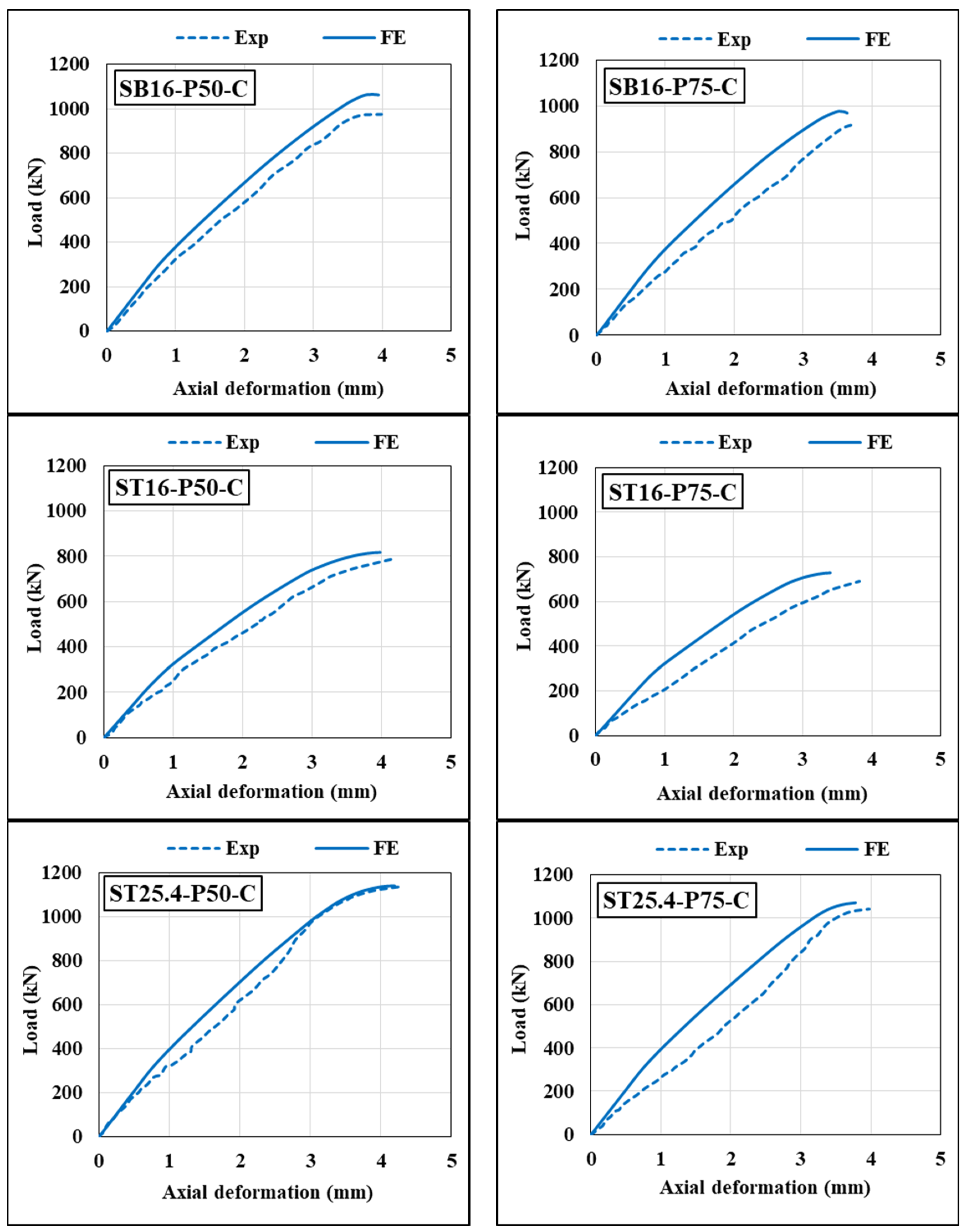
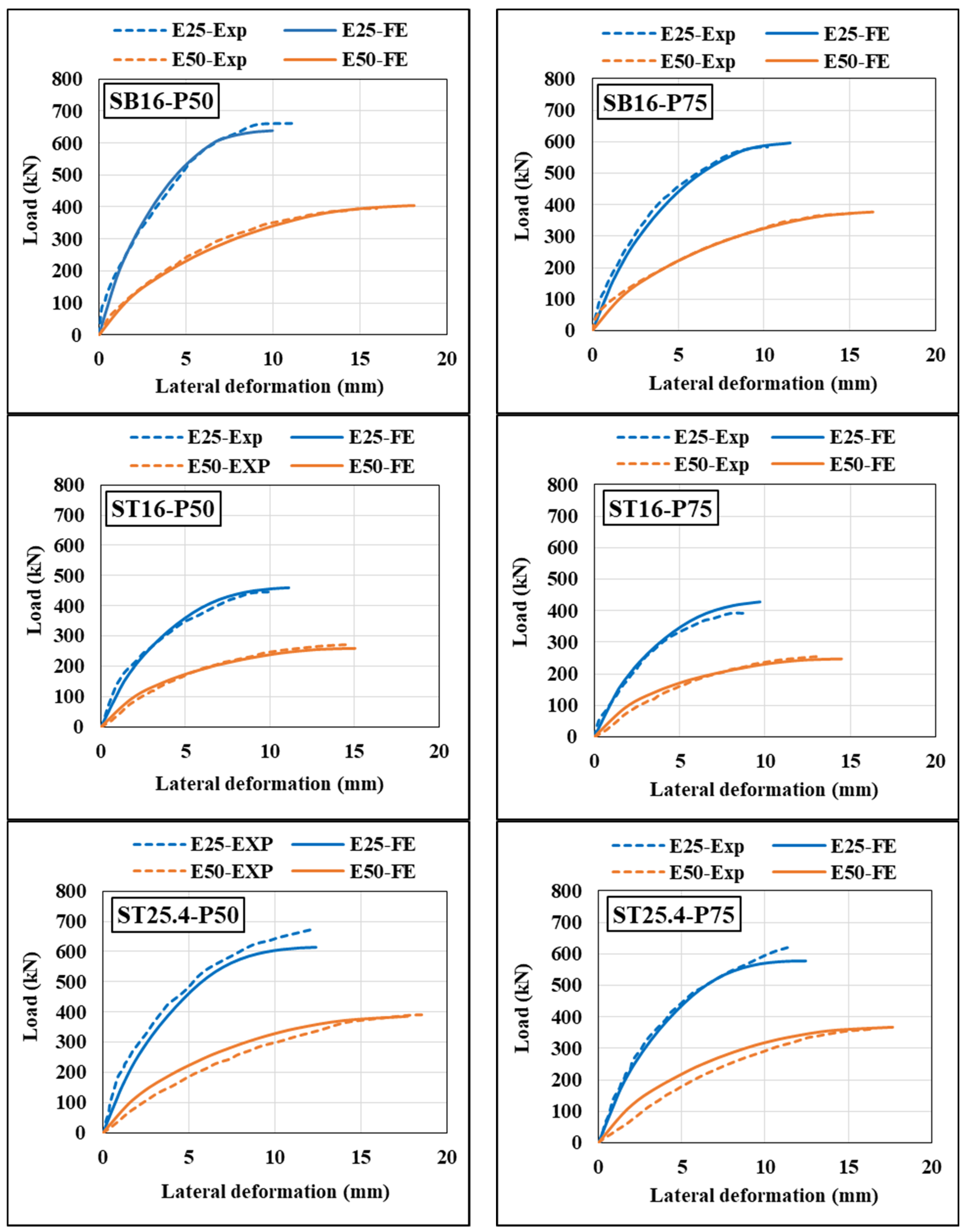
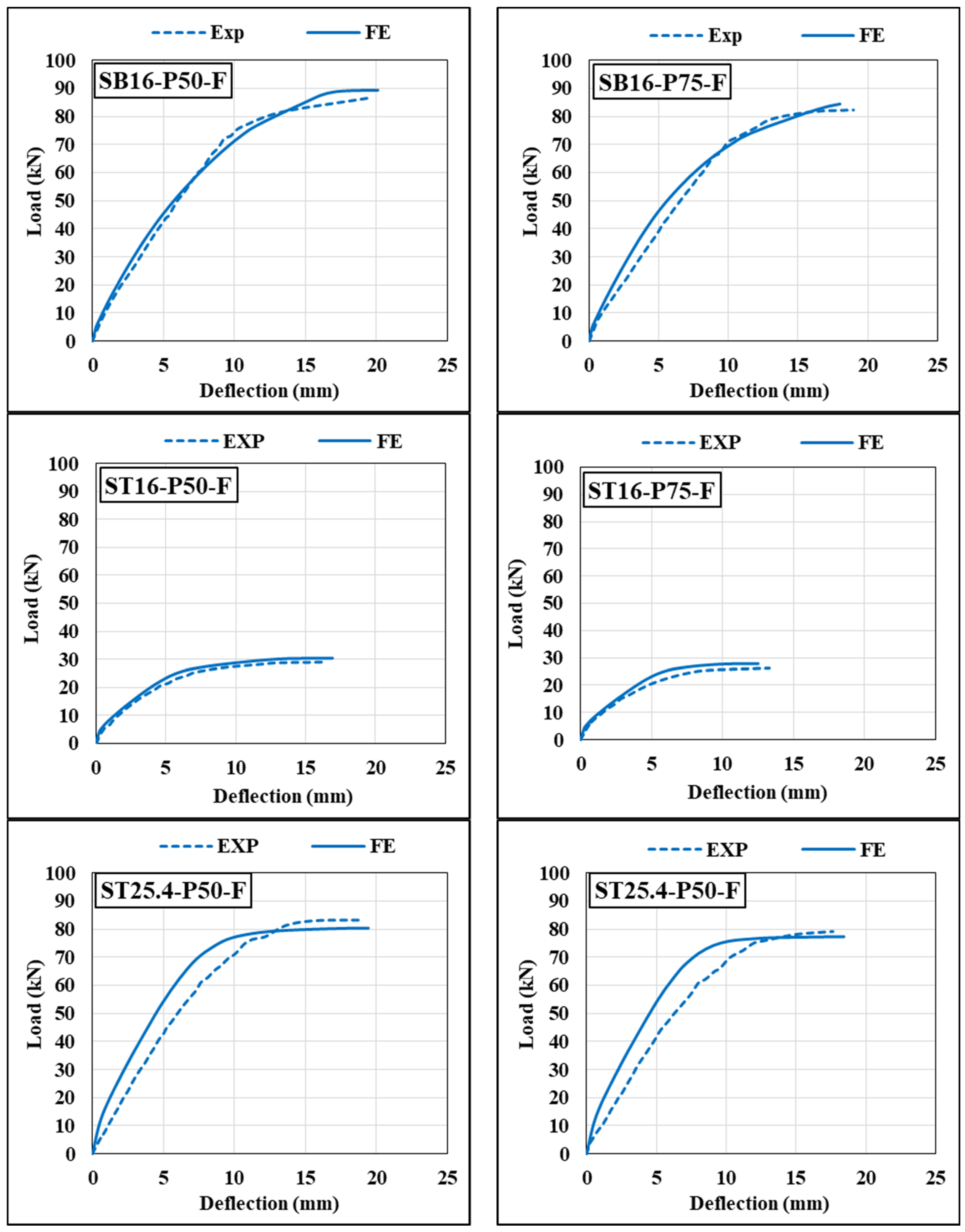
4.2. Load–Deformation Curve of CE-GFSTs Columns

The experimental load–deformation curves of all tested columns show a significant deformation increase with slight load increase before failure, as depicted in Figure 10, Figure 11 and Figure 12. The ductility is an essential indicator of the structure’s ability to maintain deformation after the elastic limit. The ductility index (DI) of columns under eccentric and flexural loads is determined by Park [38] as the ratio between ultimate load deformation u and yield deformation y , based on reduced stiffness and peak load.
Table 5 and Figure 13 provide the ductility index of the specimens that underwent testing under eccentric and flexural loads. The experimental results indicate that that specimens reinforced with 25.4 mm outer diameter steel tubes, with a reinforcement ratio equivalent to steel bars, show significantly lower ductility under eccentric and flexural loading. Steel tubes reinforced with 16 mm outer diameter columns show a lower ductility index under low eccentric load (25 mm) compared to reference specimens. However, specimens tested under high eccentricity (50 mm) and flexural load show higher ductility due to the large tension area in the concrete column section and low reinforcement ratio compared to steel bars. This is due to the creation of a large tension area in the concrete column section. Moreover, specimens with a spiral pitch of 50 mm have higher ductility than those with a pitch of 75 mm, due to the fact that the small spiral pitch achieves more confinement effect of the concrete core of the columns.
Strain in the longitudinal reinforcement (steel bars or tubes) under tension and compression was recorded during testing under eccentric or flexural loads. Table 5 lists the experimental strain at the ultimate load. The test results indicate that compression reinforcement has more strain than tension reinforcement. Tension reinforcement did not yield when subjected to 25 mm eccentric load, but yielded when subjected to 50 mm eccentric load or flexural load.
The numerical load–deformation curves determined by the FEM are compared to the experimental results and presented in Figure 10, Figure 11 and Figure 12. The load–deformation curves from FE analysis are slightly stiffer than experimental curves in linear and nonlinear regions. The assumption of a perfect bond between steel bars, tubes, and concrete causes the structure to behave more rigidly. However, a good agreement was found between the numerical FE model and experimental load–deformation curves for most tested columns.

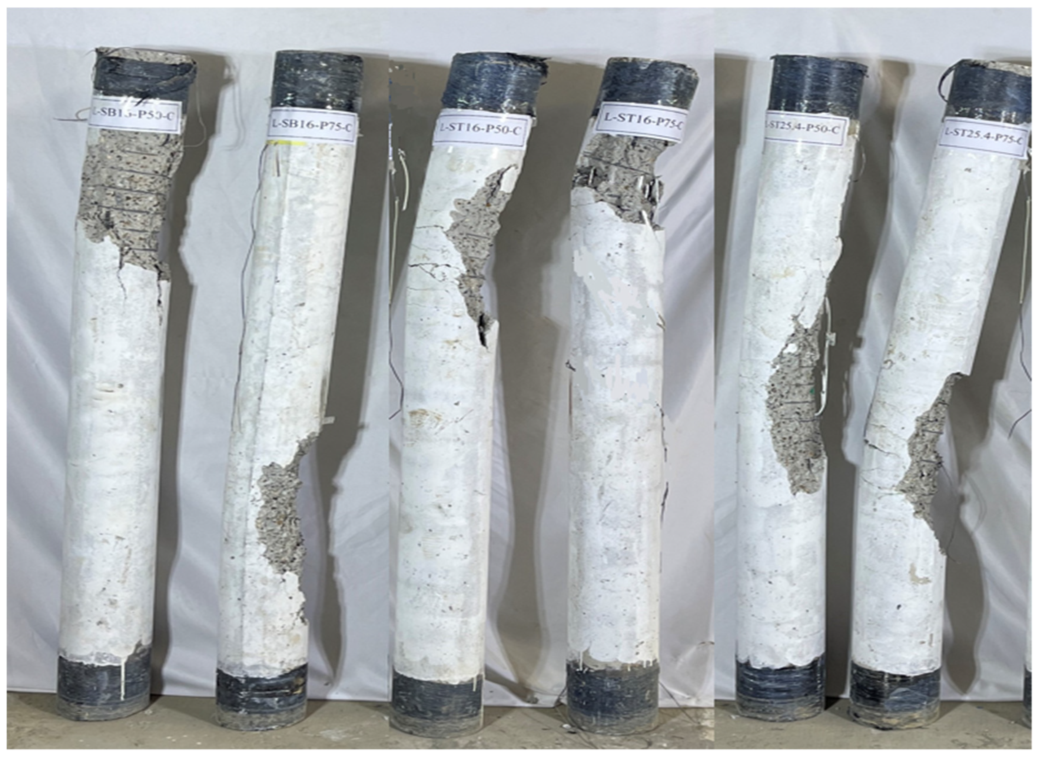
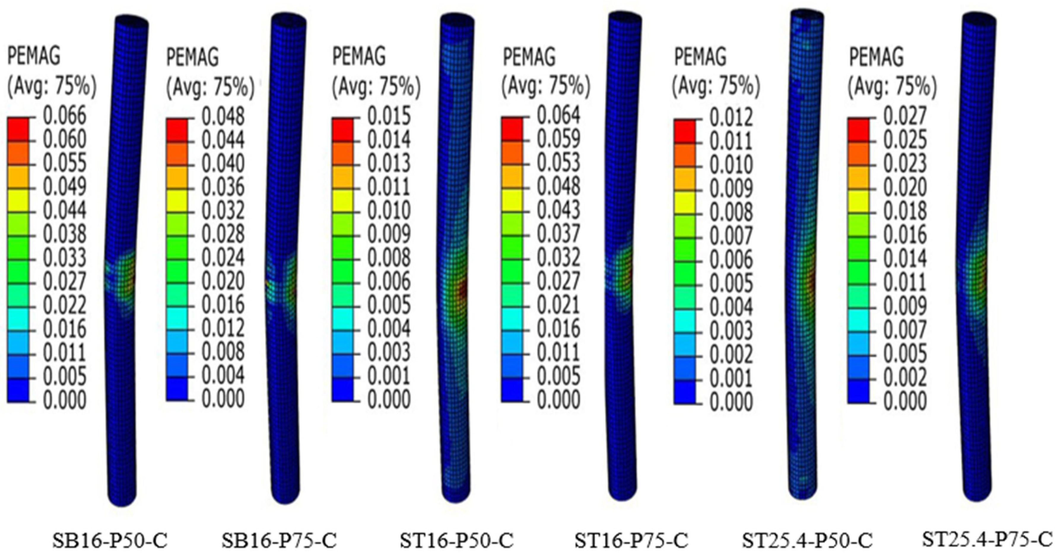
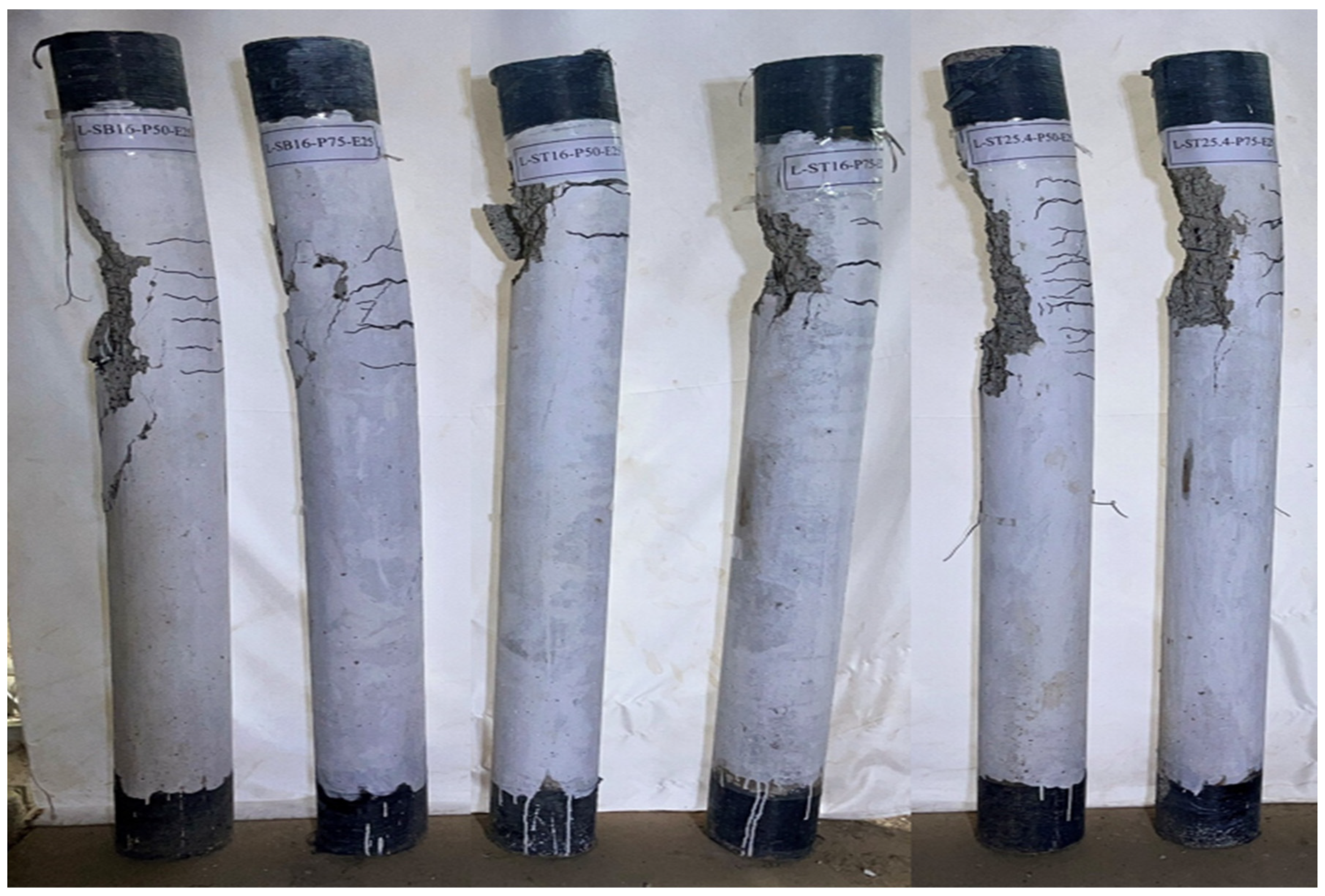
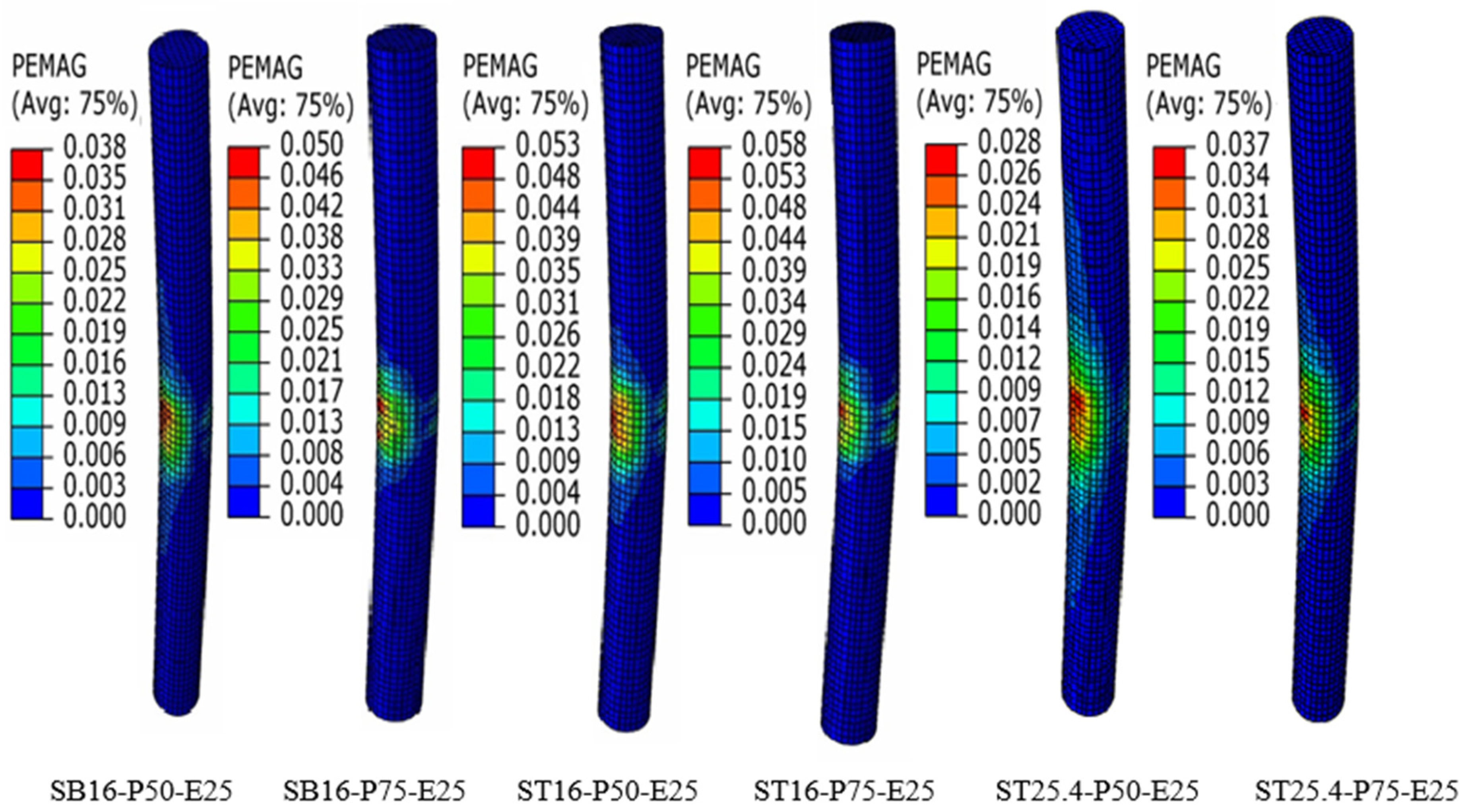
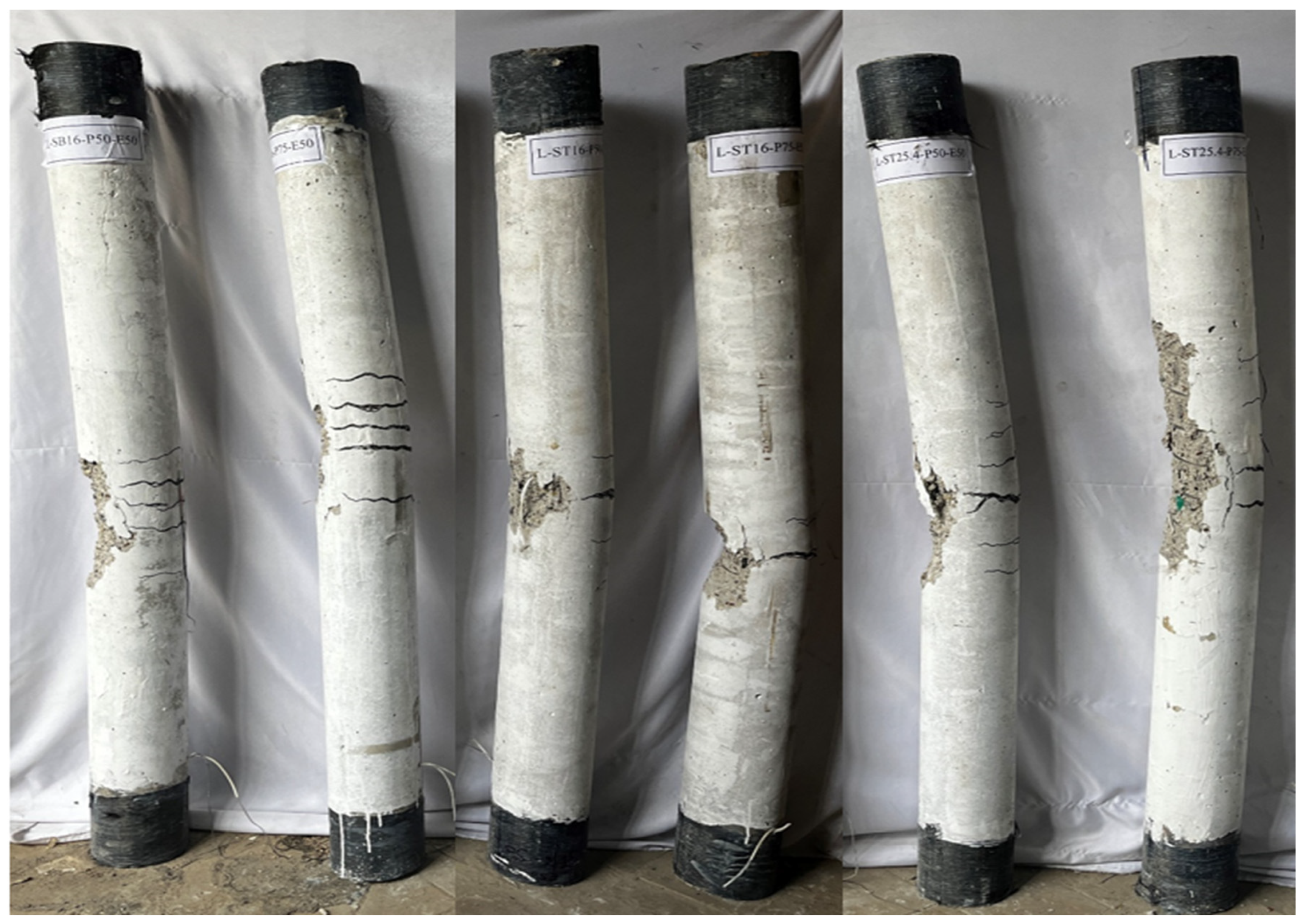
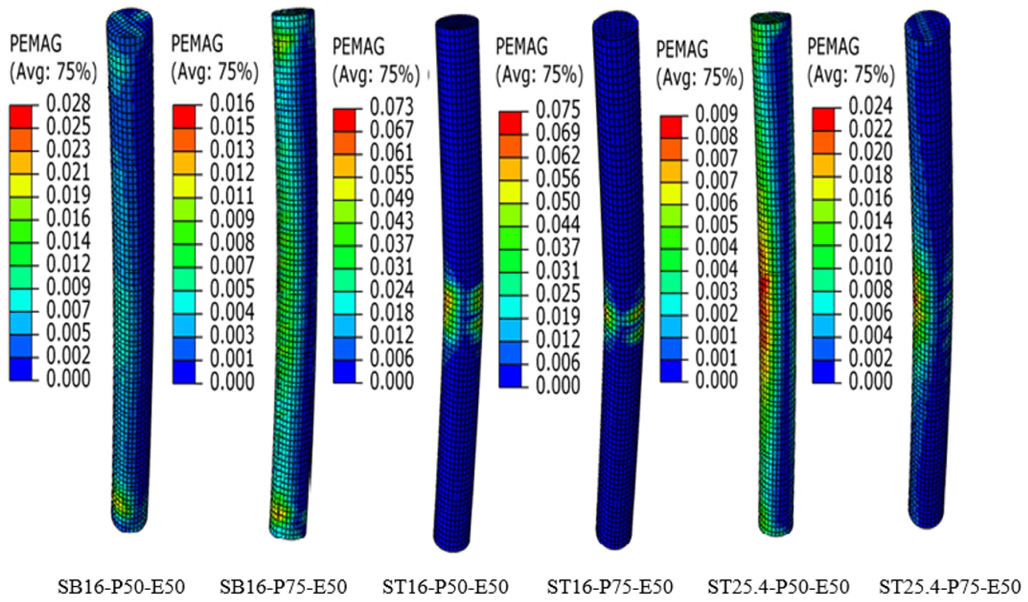
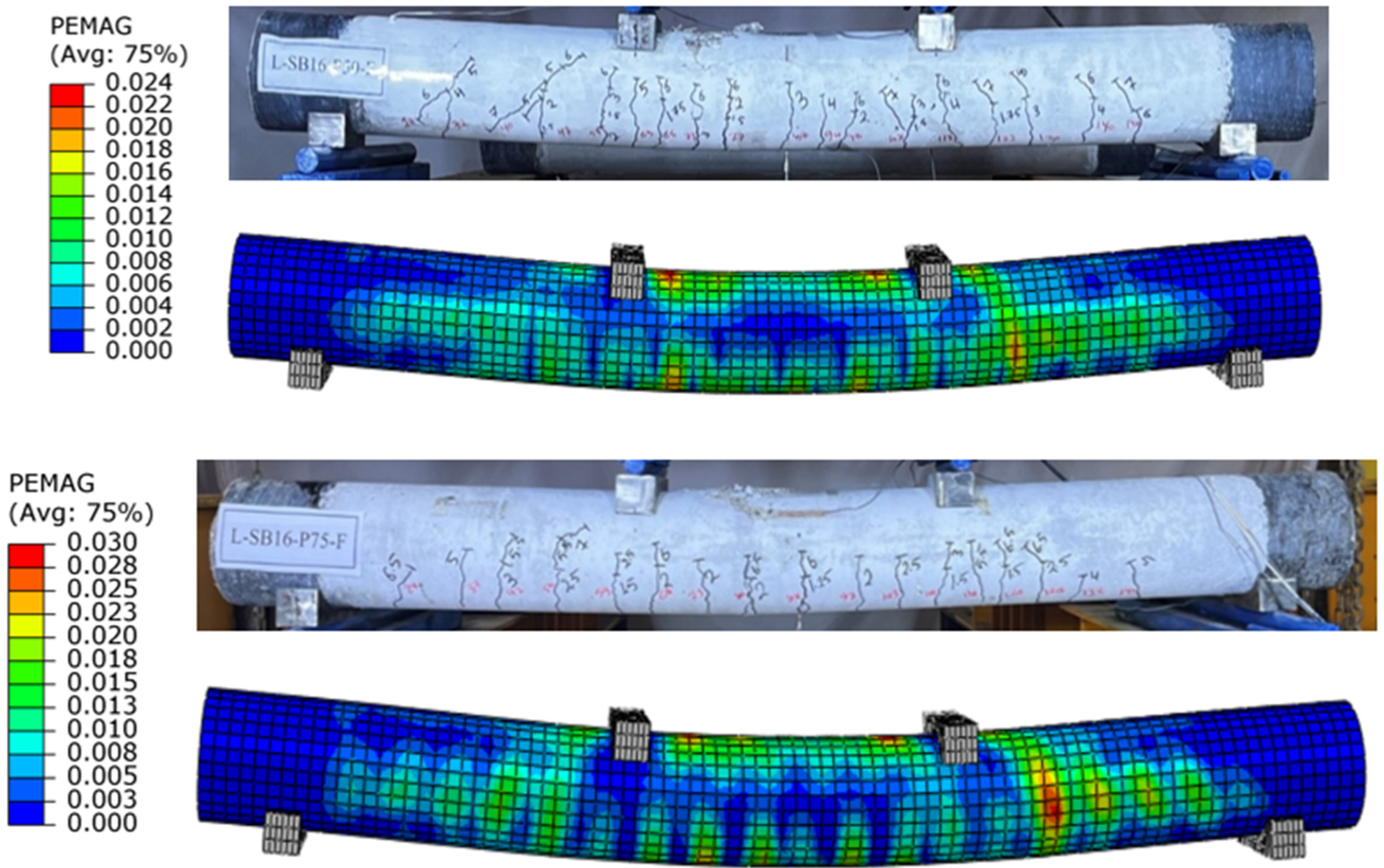
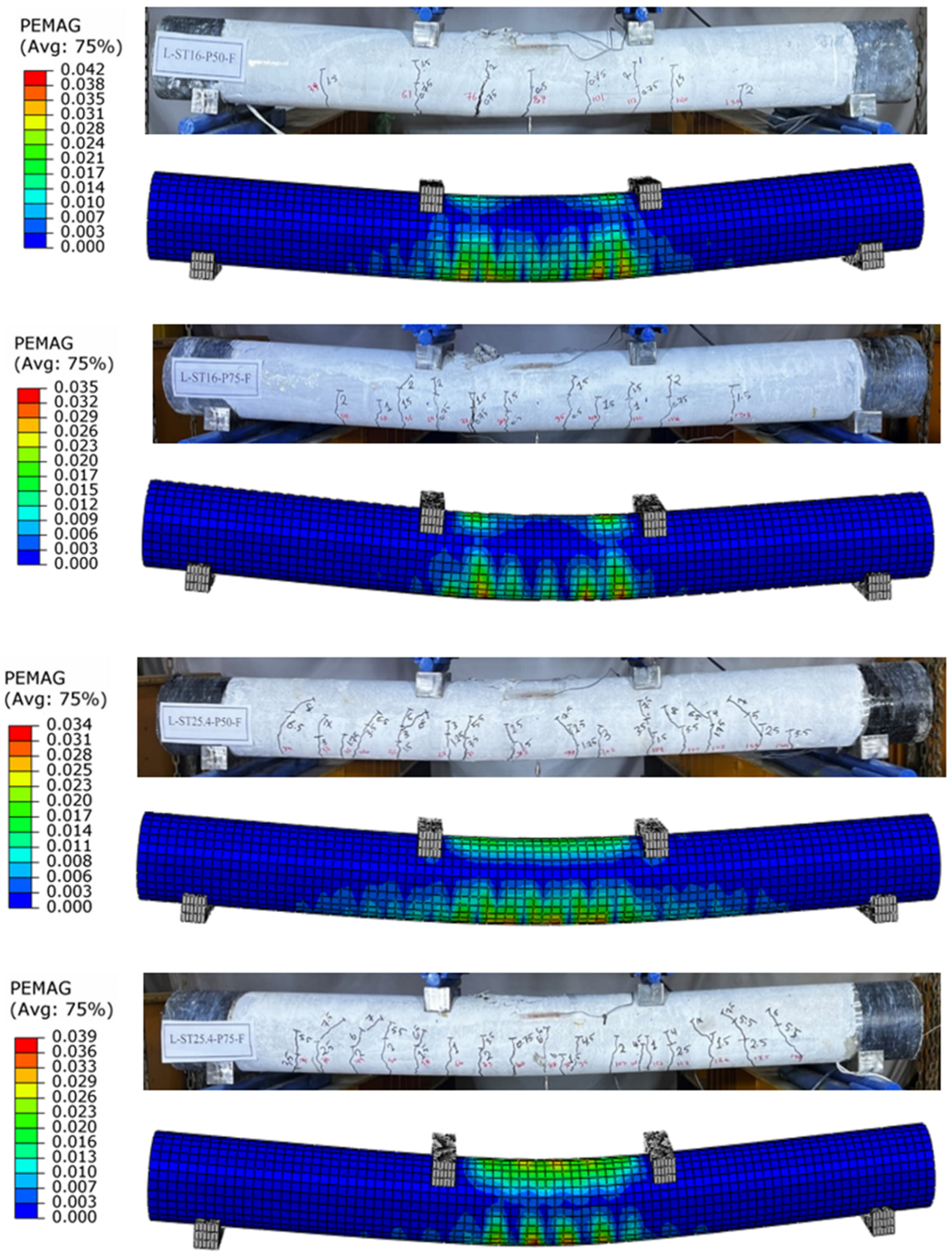
4.3. Crack Pattern and Mode of Failure

The tested specimens exhibit three failure modes based on loading type, with compression failure mode dominating for concentric columns, causing concrete cover spalling at mid-height in most cases (Figure 14). Figure 15 and Figure 16 show the overall failure mode of reinforced concrete columns under compression load with 25 and 50 mm eccentricity, respectively. The concrete column, a compression structural member, undergoes bending failure when exposed to eccentric load, resulting in a change in failure mode, as evident in the experimental failure modes of tested specimens.
The experimental failure mechanism involved compressive crushing and spalling of concrete, with a flexural–compression failure mode observed in columns under 25 mm eccentric load. No yielding occurred in tension reinforcement, and no local buckling of the inside steel tubes was observed. Tested specimens under 50 mm eccentric load showed no tensile failure mode due to tension on column cross-section, resulting in steel bars and tubes yielding and concrete crushing at compression side. The columns tested under flexural load show an initial crack at the mid-span, followed by several cracks developing within the pure bending moment region between two-point loads. As the load increased, the cracks extended upward, and new cracks appeared out of this region, as shown in Figure 17. Yielding in steel reinforcement (steel bars or steel tubes) followed by crushing in concrete was the failure mode of all tested columns under flexural load.
The experimental failure mode of columns under eccentric and flexural load revealed wider cracks in the tension zone of columns reinforced with two types of steel tubes. It was also observed that columns reinforced with 16 mm outer diameter steel tubes had fewer and larger cracks compared to those reinforced with 25.4 mm outer diameter steel tubes, and the crack spacing between main cracks was nearly equal.
The failure mode of tested columns was identified using the FE analysis and confirmed by the experimental tests, giving a good agreement of all tested specimens under different loading conditions, see Figure 14, Figure 15, Figure 16 and Figure 17.

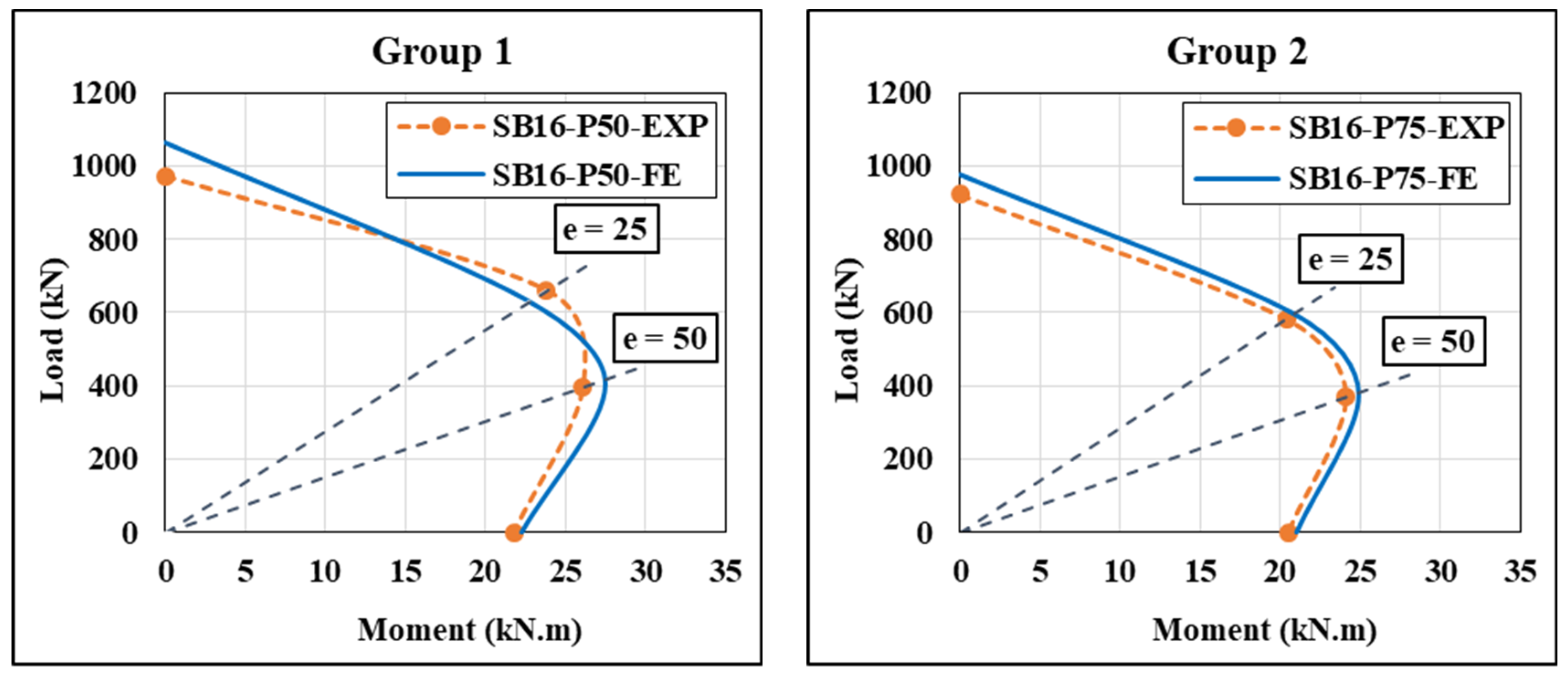
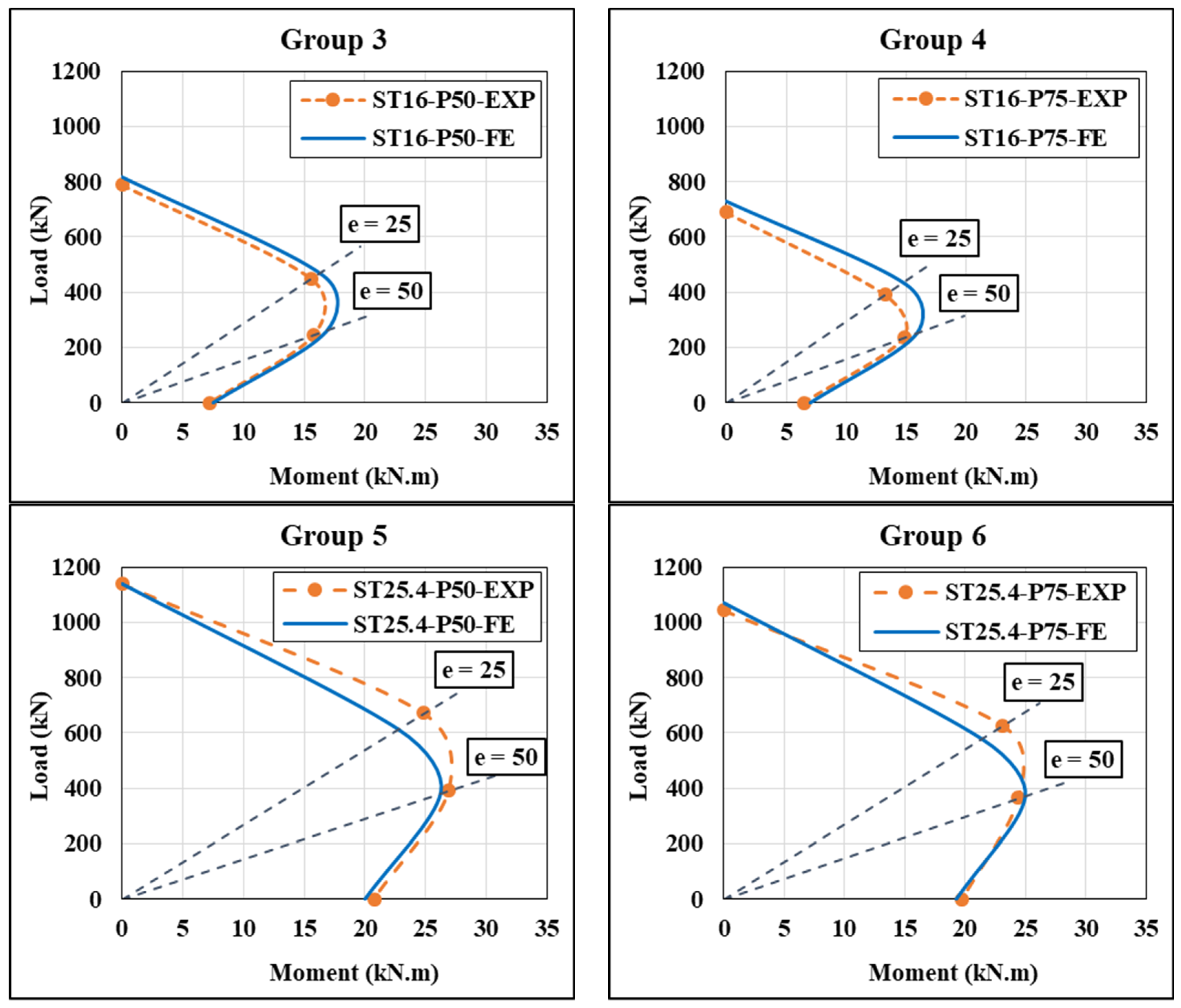
4.4. Column Interaction Diagrams

The strength interaction diagram (P–M) is plotted for a column as the load translates from a pure axial compression load through varying combinations of axial loads and bending moments to a pure bending situation. The study generates an experimental strength interaction diagram using four points: concentric load (pure compression load), 25 mm and 50 mm eccentricity load (concentric and 50 mm eccentricity load), and flexural load (pure bending). This diagram displays the acceptable bending moment and axial compression capacities of a structural concrete member. The flexural moment at mid-height of the column under two compression eccentric loads was obtained as in Equation (1), while the flexural moment when the specimen tested as a beam is calculated as in Equation (2).
M = P ( e + )
M = P l / 6
where P is the maximum applied load, e the eccentricity of the applied load, is the lateral deformation at the maximum applied load, and l is the clear span of the beam.
The FEM was used to construct numerical axial compression load–bending moment (P–M) interaction curves for all tested specimens using ABAQUS computer software. The FEA results were obtained in terms of a concentric, eccentric, and flexural load of the above-adopted columns. Figure 18 illustrates the comparative strength interaction diagrams of the experimental and numerical analysis for the six tested groups. It can be seen from the figure that the test results of the columns are almost coincident with the numerical strength interaction diagrams of the tested columns. The figure shows a similar envelope curve of columns reinforced with steel tubes (Groups 5 and 6) as compared to reference columns (Groups 1 and 2); this is because these groups have the same longitudinal reinforcement ratio (5.31%). The figure shows a significant decrease in column strength capacities for Groups 3 and 4, due to a 30% lower longitudinal reinforcement ratio than reference groups. When eccentricity is increased from 25 mm to 50 mm, columns reinforced with low reinforcement ratios change from compression-controlled to tension-controlled behavior due to the bending effect with high applied load eccentricity.

5. Conclusions

In this article, the behavior of encased concrete grouting-filled small circular steel tubes CE-GFST columns was studied experimentally and numerically. The following findings can be highlighted:
  • Replacing longitudinal steel bars with small circular steel tubes can increase the ultimate strength of columns under concentric load by 17% and 13%, respectively. The use of small circular steel tubes with a 30% reinforcement ratio resulted in an ultimate strength of 81% of the reference specimen’s strength, but this percentage decreased under eccentric or flexural loading;
  • The applied load’s eccentricity significantly impacts the ultimate strength and lateral deformation of columns, causing a decrease in specimen capacity and an increase in lateral deformation;
  • The tested specimens with the same design parameters exhibited a decrease in ultimate strength when the spiral spacing increased from 50 to 75 mm;
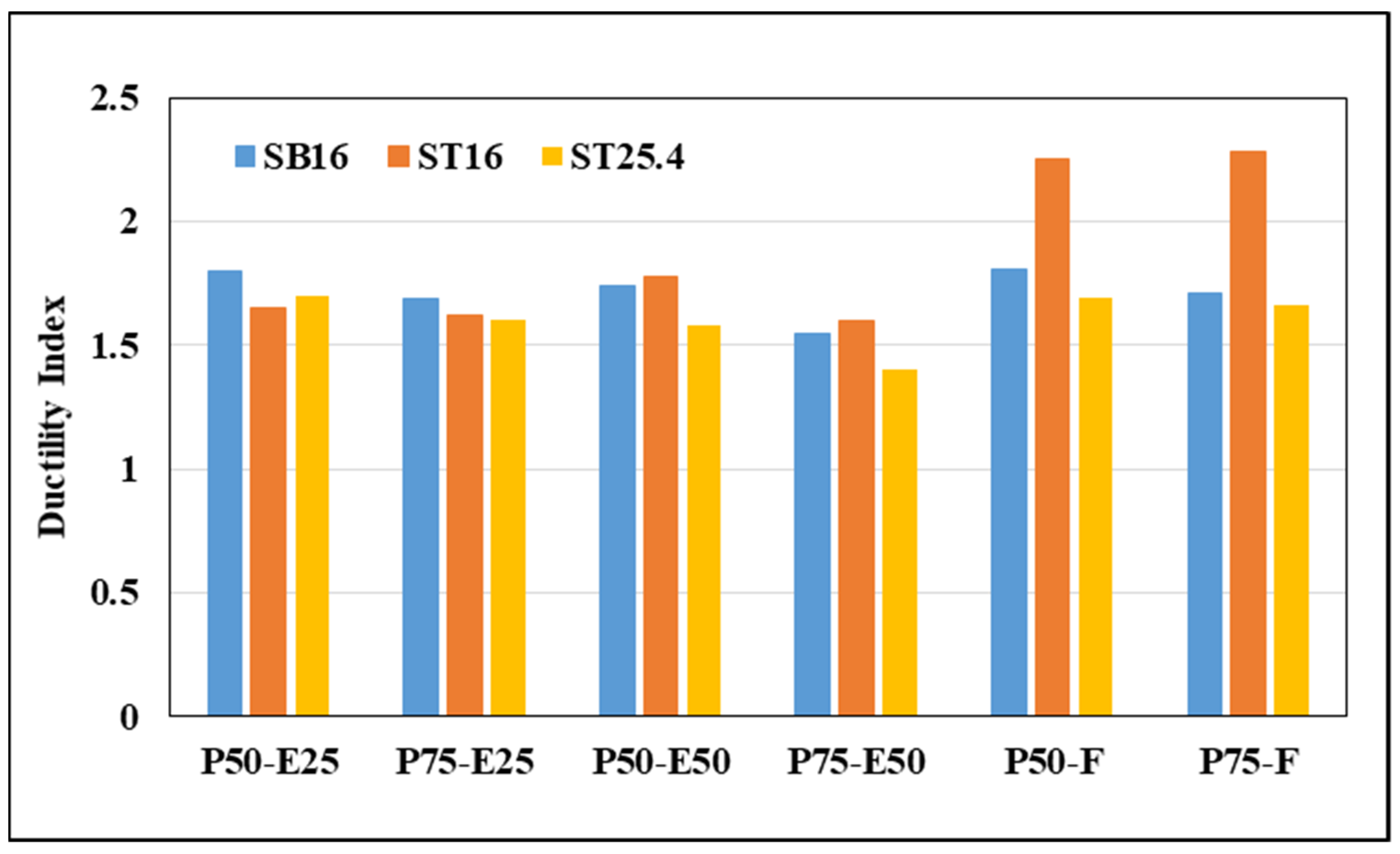
  • Three experimental failure modes of concrete-encased GFSTs columns were observed: compression failure mode for concentrically tested columns, flexural–compression failure mode for columns under 25 mm eccentric load, and tensile failure mode for columns under high eccentricity or flexural load;
  • Finite element models (FEA) were developed to simulate CE-GFST columns’ behavior under different loading conditions. Experimental results validated the models, showing high concordance with test outcomes for ultimate strength, deformation, and failure modes;
  • According to the outcomes of the present study, the first type of reinforcement—conventional steel bars—is 25% more expensive than the second type, which consists of concrete-filled steel tubes with a 30% steel bar reinforcement ratio. On the other hand, the third type—concrete-filled steel tubes with the same reinforcement ratio as steel bars—outperforms traditional steel bars in terms of failure load at the same cost. Nevertheless, the current study has several limitations, including sample size and testing circumstances within the evaluated specimens. Therefore, in order to construct steel tubes filled with cementitious grouting material that is used to reinforce columns, future research should optimize the design parameters by looking at different slenderness ratios, grades of steel tubes, compressive strength of grouting materials, etc.

Author Contributions

Conceptualization, N.O. and A.A.A. (Ahlam A. Abbood); methodology, N.O. and A.A.A. (Abbas A. Allawi); software, A.A.A. (Ahlam A. Abbood); validation, A.A.A. (Ahlam A. Abbood); formal analysis, A.A.A. (Ahlam A. Abbood), N.O. and A.A.A. (Abbas A. Allawi); investigation, A.A.A. (Ahlam A. Abbood), N.O. and A.A.A. (Abbas A. Allawi); resources, A.A.A. (Ahlam A. Abbood), N.O. and G.W.; data curation, A.A.A. (Ahlam A. Abbood), N.O. and G.W.; writing—original draft preparation, A.A.A. (Ahlam A. Abbood); writing—review and editing, N.O. and A.A.A. (Abbas A. Allawi); visualization, A.A.A. (Ahlam A. Abbood), N.O., A.A.A. (Abbas A. Allawi), and G.W.; supervision, N.O. and A.A.A. (Abbas A. Allawi); project administration, A.A.A. (Ahlam A. Abbood), N.O. and A.A.A. (Abbas A. Allawi); funding acquisition, A.A.A. (Ahlam A. Abbood), N.O. and G.W. All authors have read and agreed to the published version of the manuscript.

Funding

This research received no external funding.

Data Availability Statement

Data are contained within the article.

Acknowledgments

The authors gratefully appreciate and thank the Structural Laboratory staff of the Department of Civil Engineering at the University of Baghdad, Iraq, for their support in the experimental part of the research. In addition, the authors are grateful to and thank the Consulting Engineering Bureau at the University of Baghdad (CEB-UOB) for the assistance in fulfilling the material tests.

Conflicts of Interest

The authors declare no conflicts of interest.

References

  1. Ma, D.Y.; Han, L.H.; Ji, X.; Yang, W.B. Behaviour of hexagonal concrete-encased CFST columns subjected to cyclic bending. J. Const. Steel Res. 2018, 144, 283–294. [Google Scholar] [CrossRef]
  2. Zhou, J.; Li, P.; Guo, N. Seismic performance assessment of a precast concrete-encased CFST composite wall with twin steel tube connections. Eng. Struct. 2020, 207, 110240. [Google Scholar] [CrossRef]
  3. Alshimmeri, A.J.H. Structural Behavior of Confined Concrete Filled Aluminum Tubular (CFT) Columns under Concentric Load. J. Eng. 2016, 22, 125–139. [Google Scholar] [CrossRef]
  4. Hassooni, A.N.; Al-Zaidee, S.R. Rehabilitation of Composite Column Subjected to Axial Load. Civil Eng. J. 2022, 8, 595–611. [Google Scholar] [CrossRef]
  5. Hassooni, A.N.; Al Zaidee, S.R. Behavior and Strength of Composite Columns under the Impact of Uniaxial Compression Loading. Eng. Tech. Appl. Sci. Res. 2022, 12, 8843–8849. [Google Scholar] [CrossRef]
  6. Cai, J.; Pan, J.; Tan, J.; Vandevyvere, B.; Xiaopeng, L. Nonlinear analysis of ECC-encased CFST columns under axial compression. J. Build. Eng. 2020, 31, 101401. [Google Scholar] [CrossRef]
  7. Bonopera, M.; Chang, K.C.; Chen, C.C.; Lin, T.K.; Tullini, N. Compressive column load identification in steel space frames using second-order deflection-based methods. Inter. J. Struct. Stab. Dyna. 2018, 18, 1850092. [Google Scholar] [CrossRef]
  8. Niyirora, R.; Niyonyungu, F.; Hakuzweyezu, T.; Masengesho, E.; Nyirandayisabye, R.; Munyaneza, J. Behavior of concrete-encased concrete-filled steel tube columns under diverse loading conditions: A review of current trends and future prospects. Cog. Eng. 2023, 10, 2156056. [Google Scholar] [CrossRef]
  9. Morino, S. Design and construction of concrete-filled steel tube column system in Japan. Earthq. Eng. Eng. Seismol. 2003, 4, 51–73. [Google Scholar]
  10. Nguyen, D.H.; Kee Hong, W.; Hyo Jin, K.; Kyum Kim, S. Finite element model for the interface between steel and concrete of CFST (concrete-filled steel tube). Eng. Struct. 2019, 185, 141–158. [Google Scholar] [CrossRef]
  11. Guo, X.H.; Jiao, J.F.; Wu, Z.A.; Zhang, J.L. Research on the reinforcement mechanism and safety monitoring of heavy-duty concrete-encased CFST columns. Adva. Civil Eng. 2020, 2020, 7372345. [Google Scholar] [CrossRef]
  12. An, Y.F.; Han, L.H.; Zhao, X.L. Experimental behaviour of box concrete-encased CFST eccentrically loaded column. Mag. Conc. Res. 2013, 65, 1219–1235. [Google Scholar] [CrossRef]
  13. An, Y.F.; Han, L.H.; Zhao, X.L. Analytical behaviour of eccentrically loaded concrete-encased CFST box columns. Mag. Conc. Res. 2014, 66, 789–808. [Google Scholar] [CrossRef]
  14. Han, L.H.; An, Y.F. Performance of concrete-encased CFST stub columns under axial compression. J. Const. Steel Res. 2014, 93, 62–76. [Google Scholar] [CrossRef]
  15. Li, Y.J.; Han, L.H.; Xu, W.; Tao, Z. Circular concrete-encased concrete-filled steel tube (CFST) stub columns subjected to axial compression. Mag. Conc. Res. 2016, 68, 995–1010. [Google Scholar] [CrossRef]
  16. Hadi, M.N.; Alhussainy, F.; Sheikh, M.N. Behavior of self-compacting concrete columns reinforced longitudinally with steel tubes. J. Struct. Eng. 2017, 143, 04017024. [Google Scholar] [CrossRef]
  17. Alhussainy, F.; Sheikh, M.N.; Hadi, M.N. Axial load-axial deformation behaviour of SCC columns reinforced with steel tubes. Structures 2018, 15, 259–269. [Google Scholar] [CrossRef]
  18. Cai, J.; Pan, J.; Lu, C. Mechanical behavior of ECC-encased CFST columns subjected to eccentric loading. Eng. Struct. 2018, 162, 22–28. [Google Scholar] [CrossRef]
  19. Cai, J.; Pan, J.; Su, H.; Lu, C. Experimental study on the hysteretic behavior of ECC-encased CFST columns. Eng. Struct. 2018, 173, 107–121. [Google Scholar] [CrossRef]
  20. Chen, J.Y.; Li, W.; Han, L.H.; Wang, F.C.; Mu, T.M. Structural behaviour of concrete-encased CFST box stub columns under axial compression. J. Const. Steel Res. 2019, 158, 248–262. [Google Scholar] [CrossRef]
  21. Manjusha, K.T.; Anila, S. Finite Element Investigation of ECC Encased CFST Columns Under Eccentric Loading. Int. J. Eng. Res. Techn. 2019, 8, 274–279. [Google Scholar]
  22. Lee, H.J.; Park, H.G.; Choi, I.R. Eccentric compression behavior of concrete-encased-and-filled steel tube columns with high-strength circular steel tube. Thin-Walled Struct. 2019, 144, 106339. [Google Scholar] [CrossRef]
  23. Cai, J.; Pan, J.; Tan, J.; Vandevyvere, B.; Li, X. Behavior of ECC-encased CFST columns under eccentric loading. J. Buil. Eng. 2020, 30, 101188. [Google Scholar] [CrossRef]
  24. Hameed, M.H.; Al-Ahmed, A.H.A.; Abbas, Z.K. Enhancing the strength of reinforced concrete columns using steel embedded tubes. Mech. Adva. Mater. Struct. 2022, 29, 2008–2023. [Google Scholar] [CrossRef]
  25. ACI. Committee 318 Building Code Requirements for Structural Concrete (ACI 318-19) and Commentary (318R-19); American Concrete Institute: Farmington Hills, MI, USA, 2019. [Google Scholar]
  26. ASTM C39-18; Standard Test Method for Compressive Strength of Cylindrical Concrete Specimens. ASTM International: Conshohocken, PA, USA, 2018.
  27. ASTM C496-17; Standard Test Method for Splitting Tensile Strength of Cylindrical Concrete Specimens. ASTM International: Conshohocken, PA, USA, 2017; pp. 1–4.
  28. ASTM C78/C78M-22; Standard Test Method for Flexural Strength of Concrete (Using Simple Beam with Third-Point Loading). ASTM International: Conshohocken, PA, USA, 2022; pp. 1–3.
  29. ASTM-C469/C469M-14; Standard Test Method for Static Modulus of Elasticity and Poisson’s Ratio of Concrete in Compression. ASTM International: West Conshohocken, PA, USA, 2014; pp. 1–9.
  30. ASTM A615; Standard Specifications for Testing Methods and Definition for Mechanical Testing Steel Products. Annual Book of ASTM Standards American Society for Testing and Materials: Philadelphia, PA, USA, 2020; Section 1.01. pp. 248–287.
  31. ASTM A370; Standard Test Methods and Definitions for Mechanical Testing of Steel Products. ASTM International: Conshohocken, PA, USA, 2018.
  32. ABAQUS, version 6.14; [Computer software]; Assault Systems: Waltham, MA, USA, 2019.
  33. ABAQUS, Analysis User’s Manual, version 2019; SIMULIA/ABAQUC INC.: Dearborn, MI, USA, 2019.
  34. Elwi, A.A.; Murray, D.W. A 3D hypoelastic concrete constitutive relationship. J. Eng. Mech. Div. 1979, 105, 623–641. [Google Scholar] [CrossRef]
  35. Tao, Z.; Wang, Z.B.; Yu, Q. Finite element modelling of concrete-filled steel stub columns under axial compression. J. Constr. Steel Res. 2013, 89, 121–131. [Google Scholar] [CrossRef]
  36. Hordijk, D.A. Tensile and tensile fatigue behaviour of concrete; experiments, modelling and analyses. Heron 1992, 37, 1–79. [Google Scholar]
  37. Yun, X.; Gardner, L. Stress-strain curves for hot-rolled steels. J. Constr. Steel Res. 2017, 133, 36–46. [Google Scholar] [CrossRef]
  38. Park, R. Evaluation of ductility of structures and structural assemblages from laboratory testing. Bull. N. Z. Soc. Earth Eng. 1989, 22, 155–166. [Google Scholar] [CrossRef]
Figure 1. Cross-sections of CE-CFST columns [8].
Infrastructures 09 00026 g001
Figure 2. Schematic of cross-section dimensions and reinforcement details of tested specimens.
Infrastructures 09 00026 g002
Figure 3. Steel loading heads and saddles were used in the test.
Infrastructures 09 00026 g003
Figure 4. Typical test setup and instrumentation for (a) column specimen; (b) beam specimen.
Infrastructures 09 00026 g004aInfrastructures 09 00026 g004b
Figure 5. The mesh size of all parts of the tested specimen.
Infrastructures 09 00026 g005
Figure 6. FE boundary conditions and applied load were used in the analysis.
Infrastructures 09 00026 g006
Figure 7. Stress–strain curves of material (a) unconfined concrete in compression; (b) confined grouting material in compression; (c) concrete and grouting material in tension; (d) stress–strain for steel tube.
Infrastructures 09 00026 g007
Figure 8. Ultimate load of all tested specimens under various loading conditions.
Infrastructures 09 00026 g008
Figure 9. Effect of spiral spacing on ultimate load for specimens tested under various loading conditions.
Infrastructures 09 00026 g009
Figure 10. Experimental and numerical load–axial deformation curves of the concentric specimens.
Infrastructures 09 00026 g010
Figure 11. Experimental and numerical load–lateral deformation curves of eccentric specimens.
Infrastructures 09 00026 g011
Figure 12. Experimental and numerical load–deflection curves of flexural specimens.
Infrastructures 09 00026 g012
Figure 13. Ductility index of tested specimens under eccentric and flexural loads.
Infrastructures 09 00026 g013
Figure 14. Experimental and numerical failure mode of specimens under concentric load.
Infrastructures 09 00026 g014aInfrastructures 09 00026 g014b
Figure 15. Experimental and numerical failure mode of specimens under 25 mm eccentric load.
Infrastructures 09 00026 g015aInfrastructures 09 00026 g015b
Figure 16. Experimental and numerical failure mode of specimens under 50 mm eccentric load.
Infrastructures 09 00026 g016aInfrastructures 09 00026 g016b
Figure 17. Experimental and numerical failure mode of specimens under flexural load.
Infrastructures 09 00026 g017aInfrastructures 09 00026 g017b
Figure 18. Experimental and numerical strength interaction diagrams for the six groups.
Infrastructures 09 00026 g018aInfrastructures 09 00026 g018b
Table 1. Test matrix of the specimens.
Group No.Specimen ID *Main ReinforcementTransverse ReinforcementType of Applied Load
Diameter of Steel Bar or Tube (mm)Wall
Thickness of Steel Tube (mm)
Total Area (mm2)Reinforcement Ratio (%)Spiral Pitch (mm)Reinforcement Ratio (%)
1SB16-P50-C16-12065.31501.74Concentric
SB16-P50-E25Eccentric (25 mm)
SB16-P50-E50Eccentric (50 mm)
SB16-P50-FFlexural
2SB16-P75-C16-12065.31751.16Concentric
SB16-P75-E25Eccentric (25 mm)
SB16-P75-E50Eccentric (50 mm)
SB16-P50-FFlexural
3ST16-P50-C161.33601.59501.74Concentric
ST16-P50-E25Eccentric (25 mm)
ST16-P50-E50Eccentric (50 mm)
ST16-P50-FFlexural
4ST16-P75-C161.33601.59751.16Concentric
ST16-P75-E25Eccentric (25 mm)
ST16-P75-E50Eccentric (50 mm)
ST16-P50-FFlexural
5ST25.4-P50-C25.42.811935.31501.74Concentric
ST25.4-P50-E25Eccentric (25 mm)
ST25.4-P50-E50Eccentric (50 mm)
ST25.4-P50-FFlexural
6ST25.4-P75-C25.42.811935.31751.16Concentric
ST25.4-P75-E25Eccentric (25 mm)
ST25.4-P75-E50Eccentric (50 mm)
ST25.4-P75-FFlexural
* In the specimen ID, (SB) refers to the steel bar reinforcement, and (ST) refers to the steel tube reinforcement. The numbers (16) and (25.4) refer to the outer diameter of the steel bar or tube. The letter and number (P50) refer to a 50 mm pitch, while (P75) refers to a 75 mm pitch. Finally, C, E25, E50, and F refer to concentric, eccentricity 25 mm, eccentricity 50 mm, and flexural test.
Table 2. Mechanical properties of hardened concrete.
Type of MaterialCompressive Strength (MPa)Splitting Tensile Strength (MPa)Modulus of
Rupture (MPa)
Modulus of
Elasticity (MPa)
Concrete343.063.9627,405
Cementitious grouting material62.94.15.1437,275
Table 3. Physical and mechanical properties of steel bars and tubes used in the present study.
Type of SteelNominal Outer Diameter (mm)Actual Area (mm2)Yield Strength (MPa)Ultimate Strength (MPa)
Steel bars626.42489624
16197428542
Steel tubes25.4198.8316413
1660.03322414
Table 4. Experimental and numerical load capacity and deformation results of tested specimens.
Groups
No.
Specimens IDUltimate Load (kN) P u ( e x p ) P u ( R e f ) P u ( F E M ) P u ( e x p ) Ultimate Deformation (mm) u ( F E M ) u ( e x p )
P u ( e x p ) P u ( F E M ) u ( e x p ) u ( F E M )
1SB16-P50-C9741064Ref.1.093.993.860.97
SB16-P50-E25661639Ref.0.9611.079.970.9
SB16-P50-E50395404Ref.1.0215.9718.111.13
SB16-P50-F8789Ref.1.0219.3720.091.04
2SB16-P75-C922977Ref.1.063.763.520.94
SB16-P75-E25582596Ref.1.0210.2111.521.13
SB16-P75-E50371377Ref.1.0115.1116.341.08
SB16-P75-F8284Ref.1.0218.95180.95
3ST16-P50-C7898170.811.034.163.980.96
ST16-P50-E254484600.781.029.8911.111.12
ST16-P50-E502452590.621.0614.4615.031.04
ST16-P50-F29300.331.0316.2116.921.04
4ST16-P75-C6907290.751.053.823.40.89
ST16-P75-E253924280.671.098.749.71.11
ST16-P75-E502352470.631.0513.1314.481.1
ST16-P75-F26280.321.0713.313.000.98
5ST25.4-P50-C113811401.1714.284.20.98
ST25.4-P50-E256716141.020.9112.1212.381.02
ST25.4-P50-E503903860.990.9918.5917.710.95
ST25.4-P50-F83800.950.9618.919.421.03
6ST25.4-P75-C104310711.131.023.983.780.95
ST25.4-P75-E256255871.070.9411.612.431.07
ST25.4-P75-E503643670.981.0116.5517.661.07
ST25.4-P75-F79770.960.9717.6418.41.04
Average1.01 1.02
Standard of deviation ( σ )0.018 0.011
Coefficient of variation (COV)0.017 0.01
Table 5. Steel strain, yield deformation, ultimate deformation, and ductility index of the tested columns under eccentric and flexural load.
Loading
Mode
Specimens IDUltimate Steel Strain at Tension Zone × 10−6Ultimate Steel Strain at Compression Zone × 10−6Experimental Results
y (mm) u (mm)DI
Eccentricity
25 mm
SB16-P50-E2597734976.1511.071.80
SB16-P75-E2562331226.0510.211.69
ST16-P50-E25123336686.009.891.65
ST16-P75-E25105832015.408.741.62
ST25.4-P50-E2585232597.1012.101.70
ST25.4-P75-E2579929157.2511.601.60
Eccentricity
50 mm
SB16-P50-E50222230229.2015.971.74
SB16-P75-E50183429489.7515.111.55
ST16-P50-E50274424498.1013.201.78
ST16-P75-E50236527768.2011.501.60
ST25.4-P50-E504631414111.7518.591.58
ST25.4-P75-E503479373511.8516.551.40
FlexuralSB16-P50-F6230453010.7019.371.81
SB16-P75-F5958313211.1018.951.71
ST16-P50-F1397110717.9014.102.25
ST16-P75-F1211617457.1012.022.18
ST25.4-P50-F10282334111.2118.901.69
ST25.4-P75-F11948420710.6017.601.66
Disclaimer/Publisher’s Note: The statements, opinions and data contained in all publications are solely those of the individual author(s) and contributor(s) and not of MDPI and/or the editor(s). MDPI and/or the editor(s) disclaim responsibility for any injury to people or property resulting from any ideas, methods, instructions or products referred to in the content.

