1. Introduction
Since greenhouse gases have a great impact on the environment, various measures are being taken to reduce or perhaps even eliminate harmful emissions of exhaust gases. Trains are not big polluters in themselves [
1], but limits for harmful gas emissions are still prescribed for diesel trains by Leaflet UIC624 (
Table 1).
In order to decrease or completely eliminate the harmful emission of exhaust gases, hybrid vehicles powered by a fuel cell can be introduced [
2,
3]. Such vehicles do not pollute the environment, unlike diesel vehicles, and compared to pure battery vehicles, they have a much longer range.
The advantages of introducing hybrid fuel cell trains are:
Zero harmful emissions of exhaust gases;
Energy savings by recuperation of regenerative braking;
Reduced mass of all power sources;
Optimal power distribution on each auxiliary power source.
Table 1.
UIC624 ICE Emission Standards [
4].
Table 1.
UIC624 ICE Emission Standards [
4].
| Stage | Date | Power,
P [kW] | Engine Speed,
r [min−1] | CO | HC | NOx | PM | Smoke |
|---|
| g/kWh | |
|---|
| UIC I | up to 31 December 2002 | | | 3 | 0.8 | 12 | - | 1.6–2.5 a |
| UIC II | 1 January 2003 | P ≤ 560 | | 2.5 | 0.6 | 6.0 | 0.25 | |
| P > 560 | r > 1000 | 3 | 0.8 | 9.5 | 0.25 b | |
| r ≤ 1000 | 3 | 0.8 | 9.9 | 0.25 b | |
Hybrid vehicles can have numerous advantages over each individual component. A supercapacitor could enable instantaneous cold-start operation of auxiliary devices while the fuel cell warms up. If the temperature is not too low, the battery could run the train from the depot to the departure station during a cold start. A hybrid system can allow all drive components to be smaller in size and operate with greater efficiency since none would have to provide full load and capacity.
Fuel cells could have zero harmful emissions of exhaust gases only if the fuel is hydrogen. In general, fuel cells can also work with methanol, natural gas, and gasoline. Since such fuels, in addition to hydrogen, contain carbon, it is impossible to avoid the exhaust gas carbon dioxide. Since the aim of this paper is to achieve zero harmful emissions of exhaust gases, only hydrogen is considered as a fuel. When using hydrogen as fuel, a chemical process produces water and energy.
Software and algorithms for simulations and optimization can contribute significantly to research. Matlab software has already been used to develop train motion simulations with Object Oriented Programming (OOP). Research in [
5] shows the movement of a train with optimal driving times, which was compared with the actual railway. It showed that the simulation is very effective and applicable for the research and application of train operations.
Likewise, ADVISOR software is also a good modeling and cost-effectiveness analysis tool that was used to introduce a fuel cell hybrid locomotive. According to the traction characteristics of the Indian WDM-7 locomotive and the fuel cell as the main power source, in a certain driving cycle, the dynamic performance of the hybrid system was verified using an advanced vehicle simulator [
6].
Fuel cells, batteries, and supercapacitors are very expensive devices, and it is necessary to efficiently determine their hybridization ratios. The aim is to reduce the power of the fuel cell to the lowest value and to design the battery and supercapacitor with the lowest losses [
7]. In ref. [
8], the numerically verified methods of hybridization are presented, and thus the optimal values of the power source are selected.
The possibility of installing fuel cells in trains has already been researched [
9]. In the mentioned paper, the operation of the shunting locomotive according to the actual working cycle is presented. Energy management and power distribution between power sources were developed but without optimization. Since the shunting locomotive has demanding work, it still works on a straight railway in shorter time intervals. This is a good template for simulating a train on a mountain railway and can still show better system performance.
Matlab-Simulink™ (M/S™) can also be used to develop tools such as TrEnO, which provides tools for optimizing total energy consumption [
10]. The tool is also able to estimate the efficiency, power dissipation, and thermal behavior of the traction system components. It is used during the conceptual faze of train prototypes to optimize the overall traction and braking of trains on a given railway.
The SQP optimization tool is incorporated into the M/S™ environment [
11]. One of the first steps is to model the train speed trajectory. The minimum energy consumption can be set as an optimization goal, and a trade-off between energy consumption and accuracy can be made using the train trajectory model [
12].
In this study, the SQP algorithm is used to optimize the hybridization of power sources of the train [
13]. The model uses SQP to find the optimal hybridization ratio between the fuel cell, the battery, and the supercapacitor according to the trajectory of the train movement on the mountain railway between Knin and Perković in Croatia. The simulation itself calculates the power of the fuel cell, battery, and supercapacitor according to the given load currents of each power source [
14]. The aim is the lowest consumption of hydrogen in fuel cells [
15].
The energy management developed in this paper is based on SOC control. It is designed to maintain the charge of the battery and supercapacitor with optimal values, and the design was developed based on the prototype of a passenger train and a mountain railway.
2. Materials and Methods
2.1. Model and Topology of the Train
The train model in this work is based on the HŽ7022 prototype train of Croatian Railways. The train’s propulsion system is modeled as a hybrid of a fuel cell (FC), battery, and supercapacitor.
A passenger train has a uniform demand for maximum power during acceleration and cruising for reduced power that must overcome the force of movement resistance. In order to analyze the electricity demand of the train, a typical timetable with a railway profile was set according to the real railway in Croatia between Knin and Perković [
16].
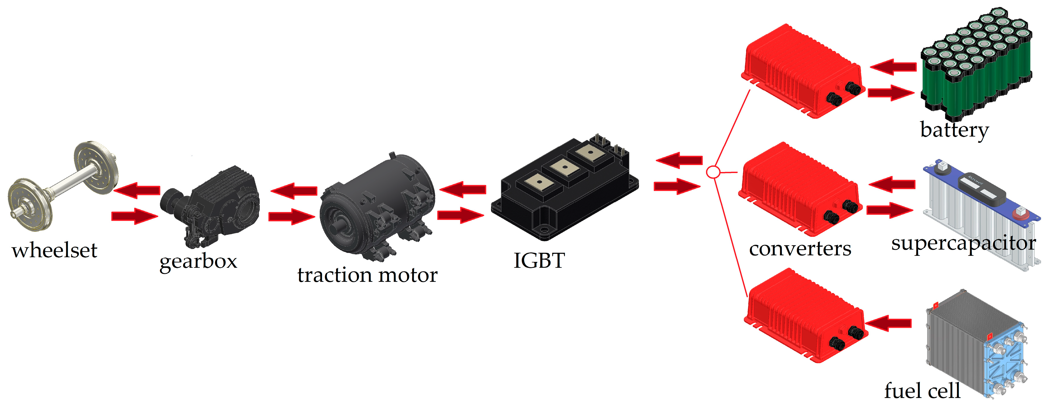
The simulation model in M/S™ calculates the traction power at the wheels according to the railway trajectory and calculates the distribution of total train power between the power sources. The traction system topology used in trains can be connected in series or in parallel. The traction hybrid system for this train is connected in series [
17] (
Figure 1). Induction motors are connected to an IGBT (insulated gate bipolar transistor) converter that is connected to DC/DC converters that are directly connected to power sources [
18]. The battery and supercapacitor are connected to bidirectional DC/DC converters for charging/discharging, while FC is connected to a chopper, a converter in one direction [
19].
According to the existing DMU (diesel multiple unit) train that will be converted into a hybrid fuel cell train, the maximum traction power is 1255 kW, and the maximum traction force is 125 kN. In a hybrid fuel cell train, the total power will be obtained from the fuel cell and auxiliary energy storage devices and taken over by the IGBT. The voltage on the IGBT is 2.4 kV, which is provided by the converters of power devices that receive a voltage of 0.8 kV. Such a high voltage generally corresponds well to the requirements of the drive system and enables lower losses in the power system.
The advantage of such a parallel system is the different voltages of the power sources. Each power source can work at its nominal voltage because the converter will raise the voltage to 2.4 kV, which is necessary for IGBT. However, it is desirable that the voltages of all power sources are approximately the same and as high as possible because the losses will be the lowest.
2.2. Energy Management System
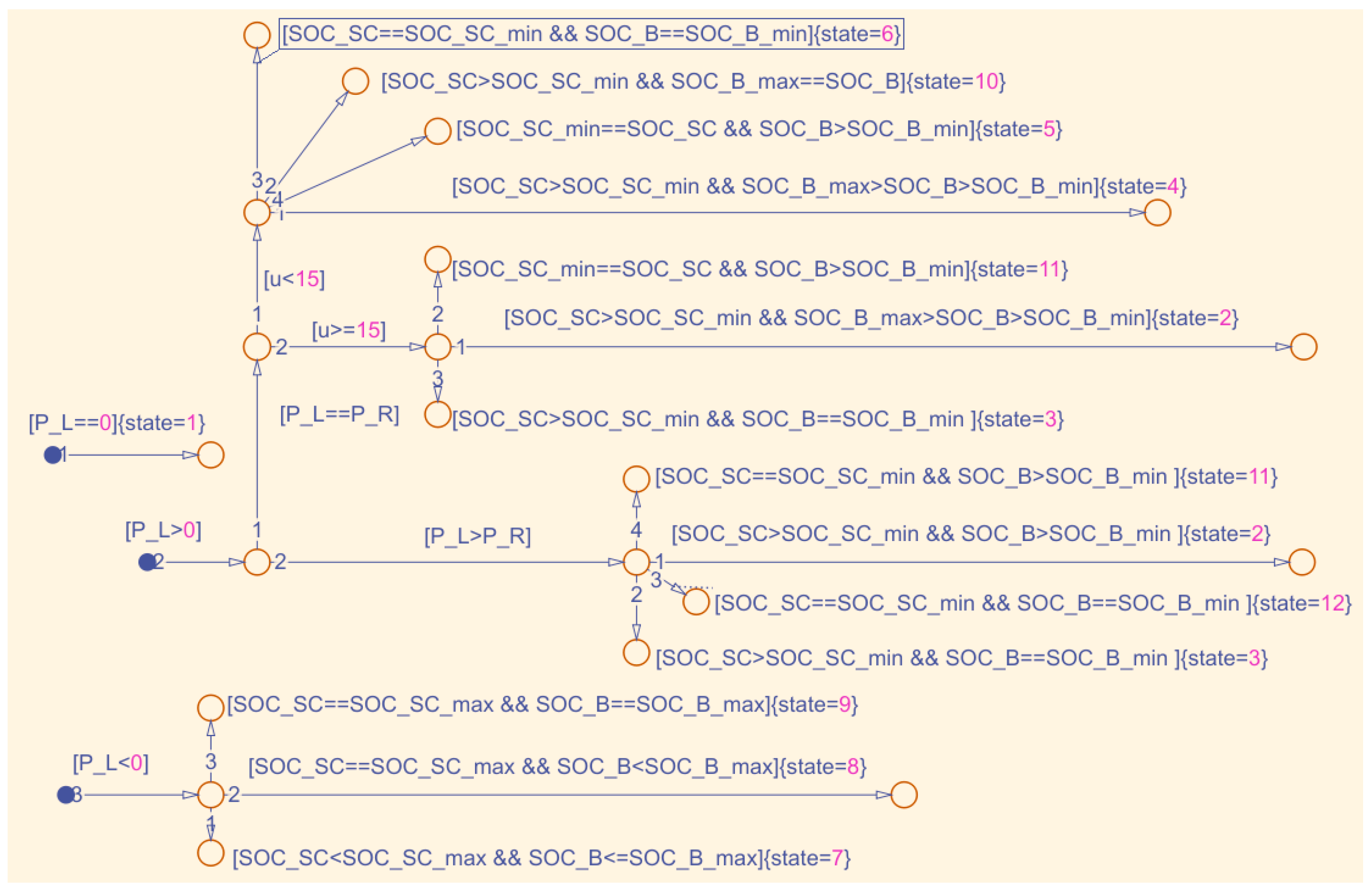
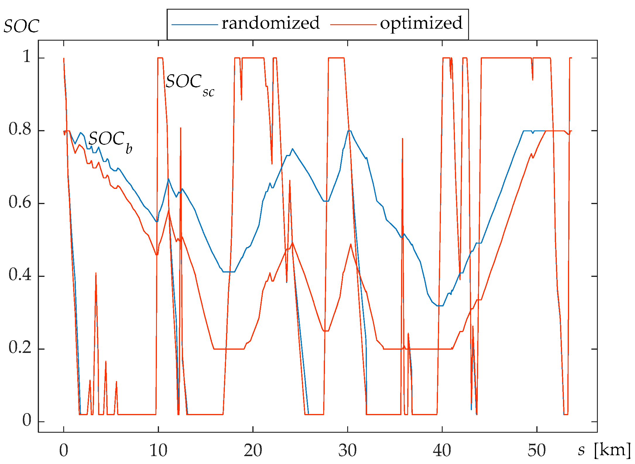
The power flow passes with losses, and the energy management coordinates the operation of power devices and distributes the power to devices according to the hybridization ratio (
Figure 2). When accelerating, energy management uses a fuel cell, battery, and supercapacitor for traction. For cruising, the supercapacitor performs traction until a state of charge
SOCsc = 0.01, and then the battery is used. If, during acceleration and cruising, the climb is greater than 15%, all devices are switched on. If
SOCb = 0.2, traction is performed by supercapacitor, and fuel cell will charge the battery. The battery drives the traction only after the supercapacitor is discharged (
SOCsc = 0.01). Regenerative braking will first charge the supercapacitor to
SOCsc =1, and the battery only will be charged after supercapacitor is fully charged. Energy management does not allow
SOCb = 0.2 and
SOCsc = 0.01 at the same time.
The hybridization ratio is affected by the total power, the properties of the railway, and the strength of the discharge currents of the fuel cell, battery, and supercapacitor.
2.3. Traction Force
Total power of the train is calculated as
where
Ftot is the total force for movement in N,
vtr is the train speed in m/s,
Pfc is the fuel cell power in W,
ηfc is the fuel cell efficiency,
ηdc is the DC/DC converter efficiency,
Pb is the battery power in W,
Psc is the supercapacitor power in W,
ηti is the traction inverter efficiency,
ηtm is the traction motor efficiency, and
ηti is the gear box efficiency. For regenerative braking, each efficiency is calculated reciprocally (1/
η), except for the fuel cell.
The total power (the total force) must be sufficient to overcome all resistances of the train:
where
Ftr is the traction force on wheels in N (positive for traction, negative for braking);
mtot is the total mass of the train in kg, increased by 6% due to the inertia of the rotating masses [
20];
rrr is the rolling resistance force in N;
rpm is the resistance coefficient of parasitic movements in N/kmh
−1;
rar is the air resistance coefficient in N/(kmh
−1)
2;
vtr is the train speed in km/h;
g is the gravitational acceleration;
grt is the gradient of the railway in ‰; and
R is the radius of curvature of the railway in m.
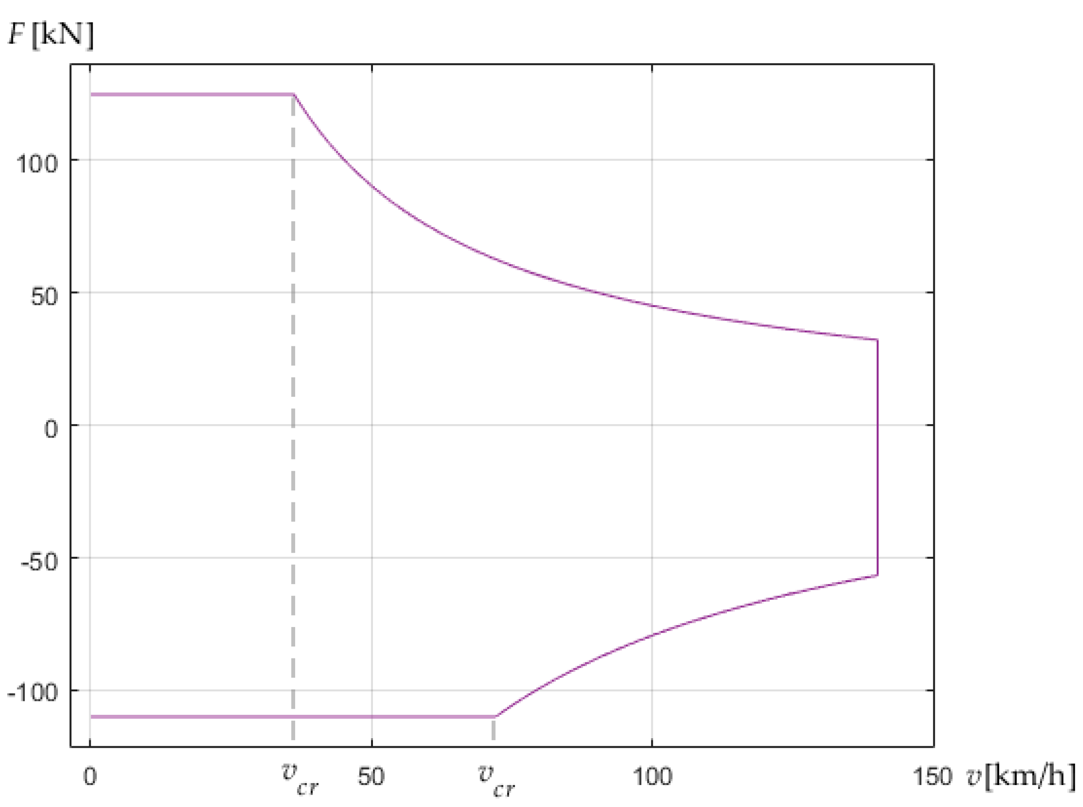
The traction force of the train is achieved up to the critical speed through torque, and after that, through the power of the traction motor. The torque is constant, and therefore the traction force is also constant. The manufacturer always provides the highest constant traction force on the wheels resulting from the torque. When a critical speed is reached, the traction force decreases with increasing speed. Accordingly, the traction force is:
For acceleration, the train will use the maximum traction force; for cruising, the traction force will be equal to the total movement resistance forces; and for regenerative braking, it will use the maximum braking force (
Figure 3).
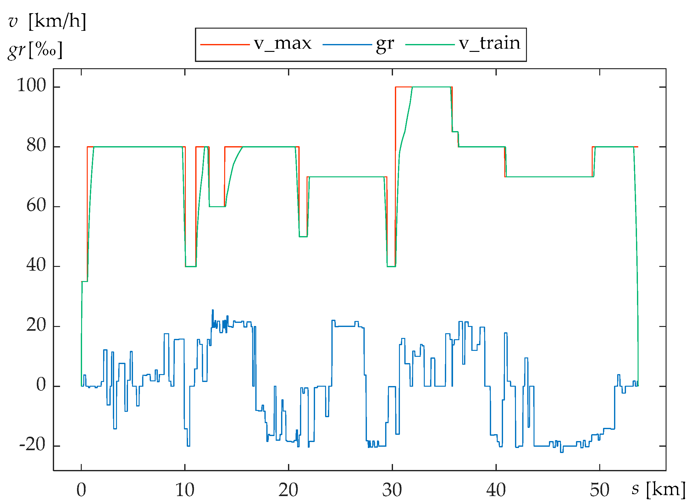
In
Figure 4, the railway profile is depicted. The yellow line represents the gradient of the railway in ‰, the red line represents the speed limit, and the blue line represents train speed.
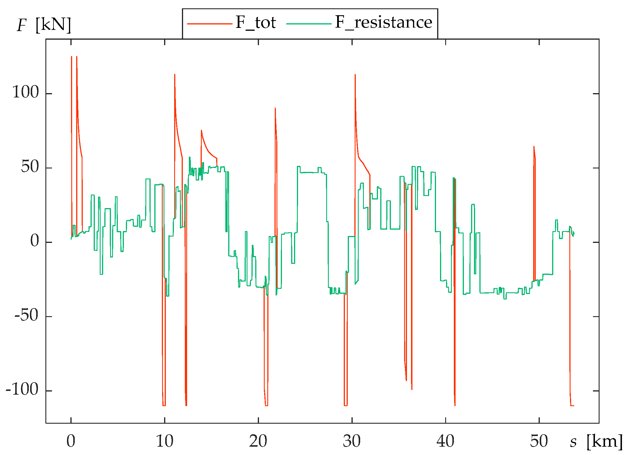
In
Figure 5, red line represents power demand, and green line represents resistance force of the railway.
Based on the railway profile data depicted in
Figure 5 and train parameters, resistance power and demand power were calculated.
Figure 4 shows the calculated power distribution on the railway. Green line represents calculated resistance power, and red line represents the necessary traction power for the simulated train.
The railway is extremely hilly and full of radiuses, which thoroughly tests the endurance of all power sources and shows whether regenerative braking can store enough energy to make the system sustainable.
2.4. Fuel Cell
Fuel cells are devices that convert chemical energy into electrical energy. The fuel cell system contains a fuel supply system, an air supply system, a water management system, and a fuel cooling system. They include AFC (alkaline fuel cell), PEMFC (Polymer Electrolyte Membrane), DMFC (Direct Methanol), PAFC (Phosphoric Acid), MCFC (Molten Carbonate), and SOFC (Solid Oxide). Only PEMFC has zero harmful emissions of exhaust gases.
PEMFC operates at relatively low temperatures and has a high power density. It cannot change the output power very fast, so PEMFC has slow dynamics. This can be compensated by faster dynamics from storage devices. The voltage of one cell is about 1 V with a current density of 0.5 A/cm2 to 1 A/cm2. To obtain higher power, the cells are joined in stacks. The fuel is hydrogen, and pure oxygen or oxygen from the air can be used as an oxidant.
PEMFC can reach 1.3 kW/L power density, 0.6 kW/L system power density, and 0.6 kW/kg mass-specific power density. It operates at low temperatures and can be started and operated in sub-zero temperatures, although normal operating temperatures are 20–90 °C [
21]. For the above reasons, PEMFC was chosen for this study, even though other cells exist.
The load power of the fuel cell stack is:
where
Ufc is the fuel cell stack voltage in V,
ILoad,fc is the fuel cell current load in A,
Eoc is the open circuit voltage in V,
Uohm is the ohmic voltage drop in V, and
Uact is the activation voltage drop in V [
22].
2.5. Battery
Lithium iron phosphate (LiFePO
4) is the safest cathode material used for the high-power modules required in hybrid vehicles. The advantages of this type of battery are the theoretical specific capacity of 170 Ah/kg and greater thermal stability against the release of oxygen, which makes it safer and more tolerant under extreme operating conditions [
23].
It can change the output power much faster than a fuel cell, so it can compensate for power in the fuel cell. In the nominal operating range of the battery, during discharge, the voltage changes slightly. When the rated capacity is discharged, the battery enters the operating range, where the battery voltage decreases rapidly.
The load power of the battery cell for discharging is:
where
Ub is the battery cell voltage in V,
E0 is the constant voltage in V,
K is the polarization constant or the polarization resistance in Ω,
Qb is the standard battery capacity in Ah,
ILoad,b is the battery current load in A,
Rb is the battery internal resistance in Ω,
A is the voltage drop during the exponential zone in V, and
B is the exponential time inverse constant in Ah
−1.
The load power of battery for charging is:
2.6. Supercapacitor
Supercapacitor (EDCL, Electrochemical Double Layer Capacitors) is a device used for energy storage, and it has high energy and power densities, high efficiency (almost 95%), and long lifetime. The main property of supercapacitor is the possibility of rapid charging and discharging without loss of efficiency (>95%) during thousands of cycles [
24].
Supercapacitors can be recharged in a very short time and have an excellent ability to change the output power very fast, faster than battery, and to operate with frequent peak power demands. All these reasons improve the efficiency of the vehicle and save energy, so they are suitable for installation. They especially show their excellent properties during regenerative braking.
The load power of the supercapacitor cell is:
where
Usc is the voltage of the supercapacitor cell in V,
R1 is the resistance of the supercapacitor’s main cell in Ω,
ILoad,sc is the supercapacitor’s load current in A,
U1 is the voltage of the supercapacitor’s main cell in V,
C0 is the constant capacitance in F,
Cv is the constant parameter in F/V, and
Q1 is the instantaneous charge in the supercapacitor’s main cell in As.
2.7. Method of Sequential Quadratic Programming
To solve the nonlinearity and non-convexity of the resulting optimal control problem, sequential quadratic programming is used [
25]. SQP is used to optimally control the management of power sources with the aim of the lowest amount of fuel consumption.
The main objective function for minimization is:
where
v(
t) is the speed of the train;
s(
t) is the distance; and
u(
t) is the set of all variables that affect driving, as shown by Equation (3).
To obtain the minimum fuel consumption, which is directly a function of energy, it is necessary to determine the discrete-time formulation of the problem. The problem of energy consumption is defined by hybridization ratios [
26]. Minimization is achieved by composing a Quadratic Programming (QP) subproblem based on the quadratic approximation of the Lagrange function [
27].
where
f(
x) is the main objective function,
gi(
x) are the inequality constraints,
λi are Lagrange multipliers under the non-negativity constraint, and
m is the total number of restrictions.
QP subproblem is given by
where
d is the number of iterations,
Hk is the Hessian Matrix, and
me is the equality constraints number. Updated, the Hessian Matrix is:
where
Duration of the simulation in time, boundary conditions, and time-dependent constraints and control variables are:
where
ILoad,sc is the discharge current of the supercapacitor,
ILoad,b is the discharge current of the battery,
SOCsc is the state of charge of the supercapacitor,
SOCb is the state of charge of the battery,
hrsc is the supercapacitor hybridization ratio, and
hrb is the battery hybridization ratio.
2.8. Model Parameters
In the simulation model, the PEMFC modules “Ballard” Fcvelocity-HD6, rechargeable LFP battery “Lithium Werks” 26650, and “Maxwell” supercapacitor BCAP3000 were used (
Table 2). According to the proportion of hybridization, the power used to discharge the battery and the supercapacitor was determined. In the simulation model, it was set that the algorithm optimizes the discharge current and thus obtains the optimal hybridization ratio for both the battery and the supercapacitor. As a result, the optimal discharge current of both the battery and the supercapacitor was obtained. The load currents are:
where
npar,sc is the number of supercapacitor cells in parallel,
nser,sc is the number of supercapacitor cells in series,
npar,b is the number of battery cells in parallel,
nser,b is the number of battery cells in series, and
Ptot is demand power.
The fuel cell stack load current is:
where
hrfc is the fuel cell stack hybridization ratio, and
npar,fc is the number of fuel cell stacks in parallel.
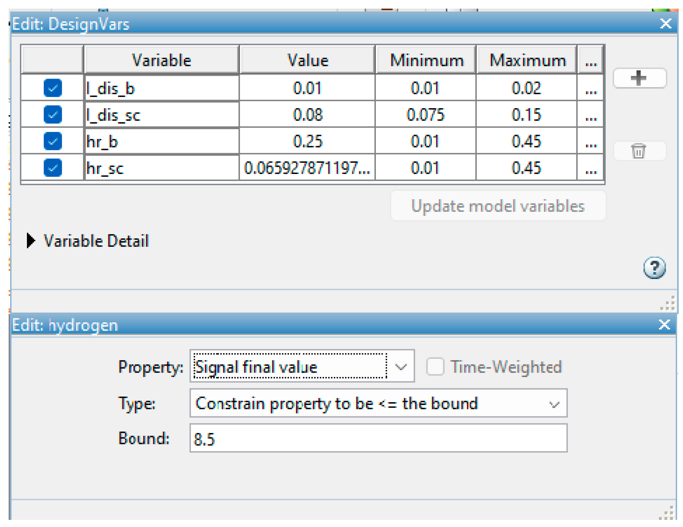
First, the optimization parameters with boundaries in the simulation and the objective function with the final desired value are selected (
Figure 6).
Boundaries for the hybridization ratio have been proven, and it has already been shown that with the ratio
hrb/
hrfc = 0.33, the vehicle can travel the most kilometers per kilogram of hydrogen. Since the supercapacitor also participates in traction, the upper boundary is 0.45 for both energy stores, as there is space for optimization. If the system does not converge, the values will expand [
28].
Energy storages discharge current constraints are set according to the manufacturer’s datasheet.
3. Results and Discussion
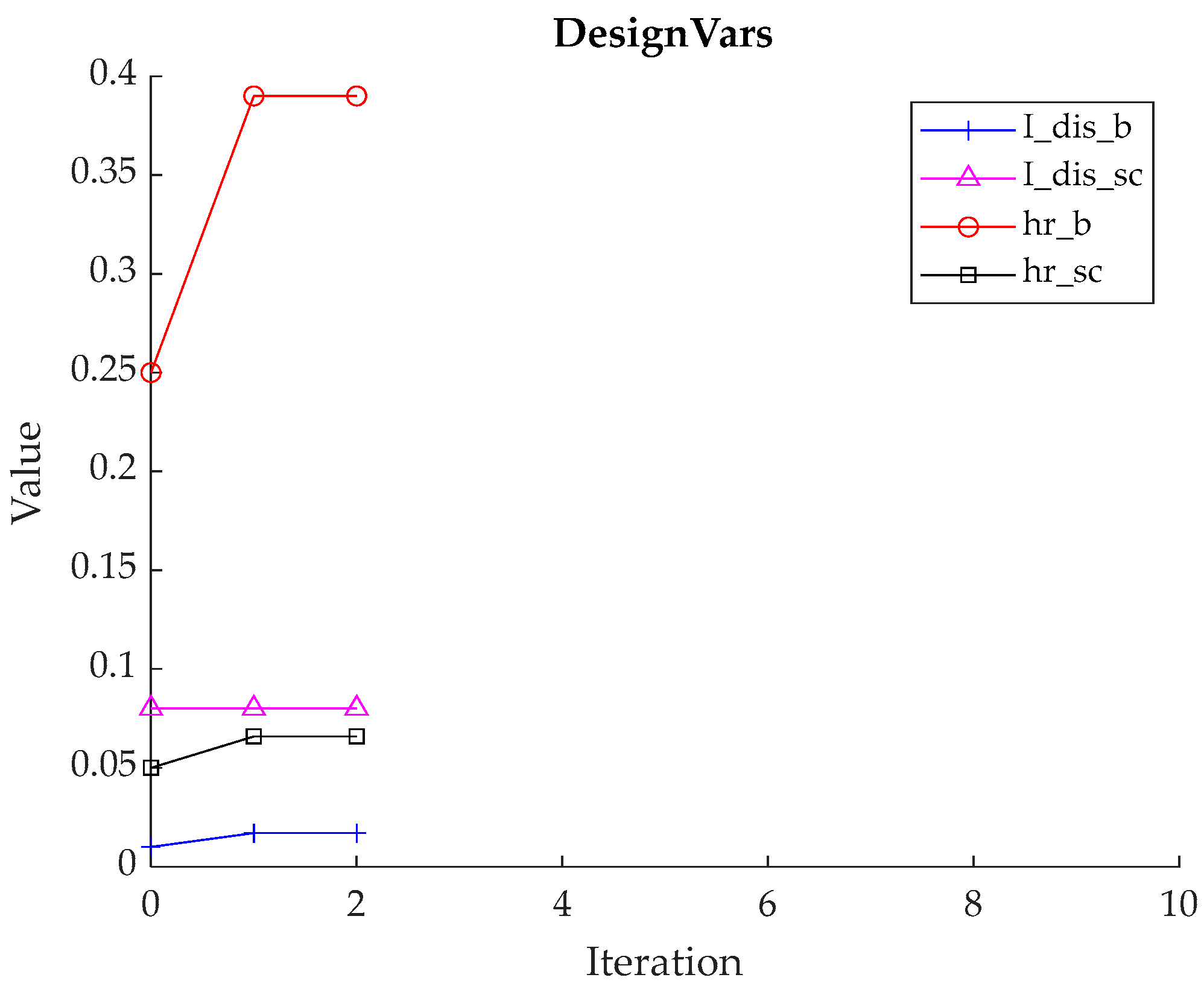
In the simulation, randomly selected parameters were taken and then optimized. Simulation results are values for the battery hybridization ratio, supercapacitor hybridization ratio, battery discharge current, and supercapacitor discharge current. Optimal parameter values for the presented study were obtained through iteration (
Table 3,
Figure 7).
The optimal values were calculated through 2 iterations.
Figure 7 depicts the iteration process.
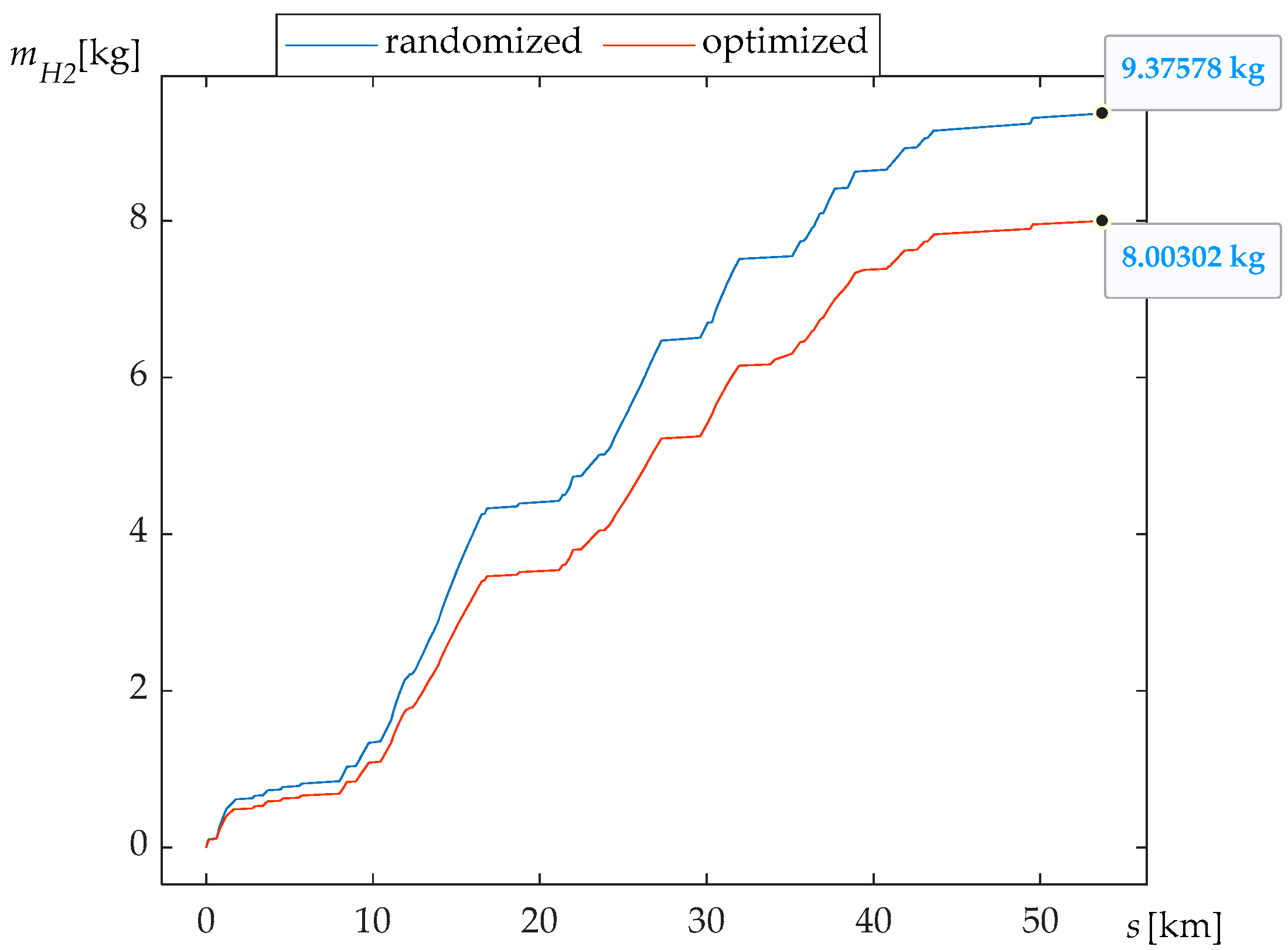
With the optimal parameters for the proposed hybrid system, the consumption of hydrogen is 8 kg over a distance of 53.71 km, which the train travels in 2717 s. During acceleration or when driving uphill, energy management uses the power of the fuel cell, the battery, and the supercapacitor together. When cruising, the supercapacitor is first completely discharged, and then the battery is used. In order not to discharge both the battery and the supercapacitor at the same time, energy management determines the optimal hybridization ratio. Likewise, if only the supercapacitor is pulling the train, the fuel cell charges the battery. The hybridization ratio of the fuel cell is obtained by hrfc = 1 − hrb − hrsc, which determines the power of the fuel cell and can be said to be optimal.
All that data can be graphically shown with the presented simulation model.
Figure 8 shows the difference in hydrogen consumption for randomly selected and optimized parameters of the propulsion system. The optimized solution yields a decrease in fuel consumption of 14.7%. That is a saving of 1.373 kg of hydrogen compared to the initial solution.
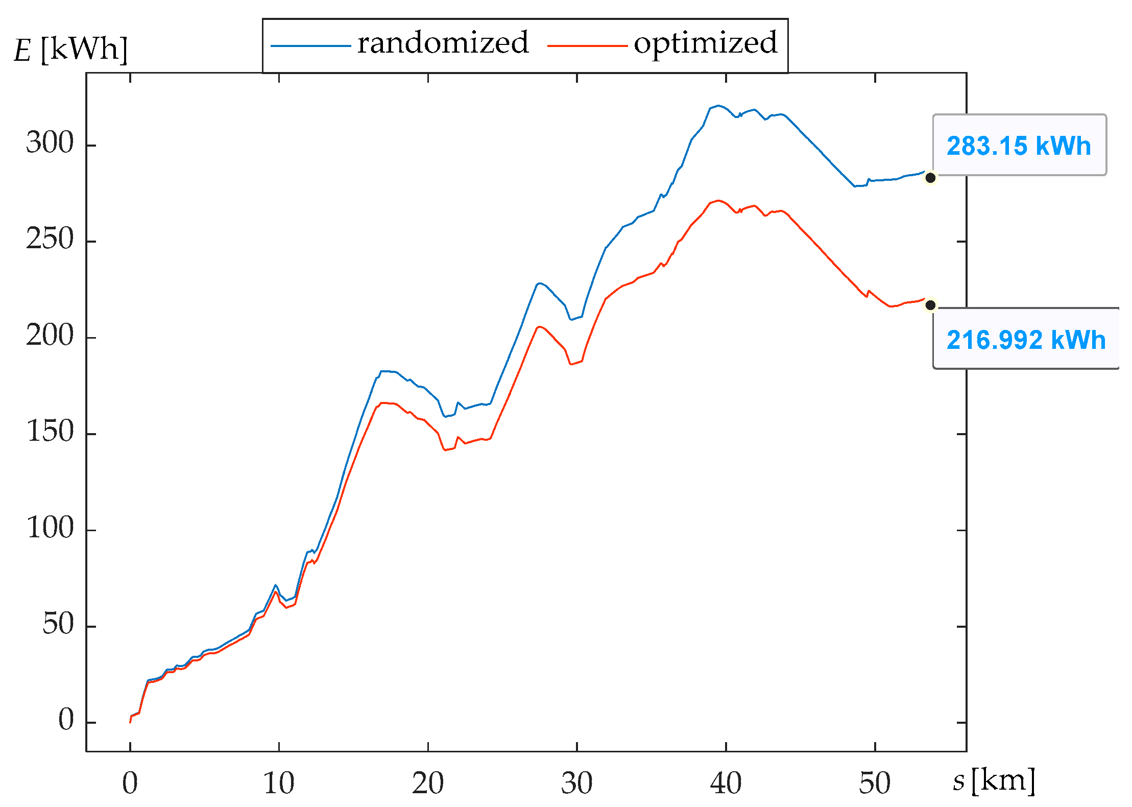
Since hydrogen consumption is a consequence of energy consumption, the consumed energy for the optimized solution is 216.99 kWh (
Figure 9). Compared to the initial solution of 283.15 kWh, the optimized system results in a decrease in energy consumption of 23.37%. Due to the optimal selection of parameters and energy management that uses power sources according to given conditions, savings are possible. The profile of the railway with pronounced uphills and downhills enables regenerative braking, which is optimally used to discharge and charge the energy storage and thus save energy (
Figure 10).
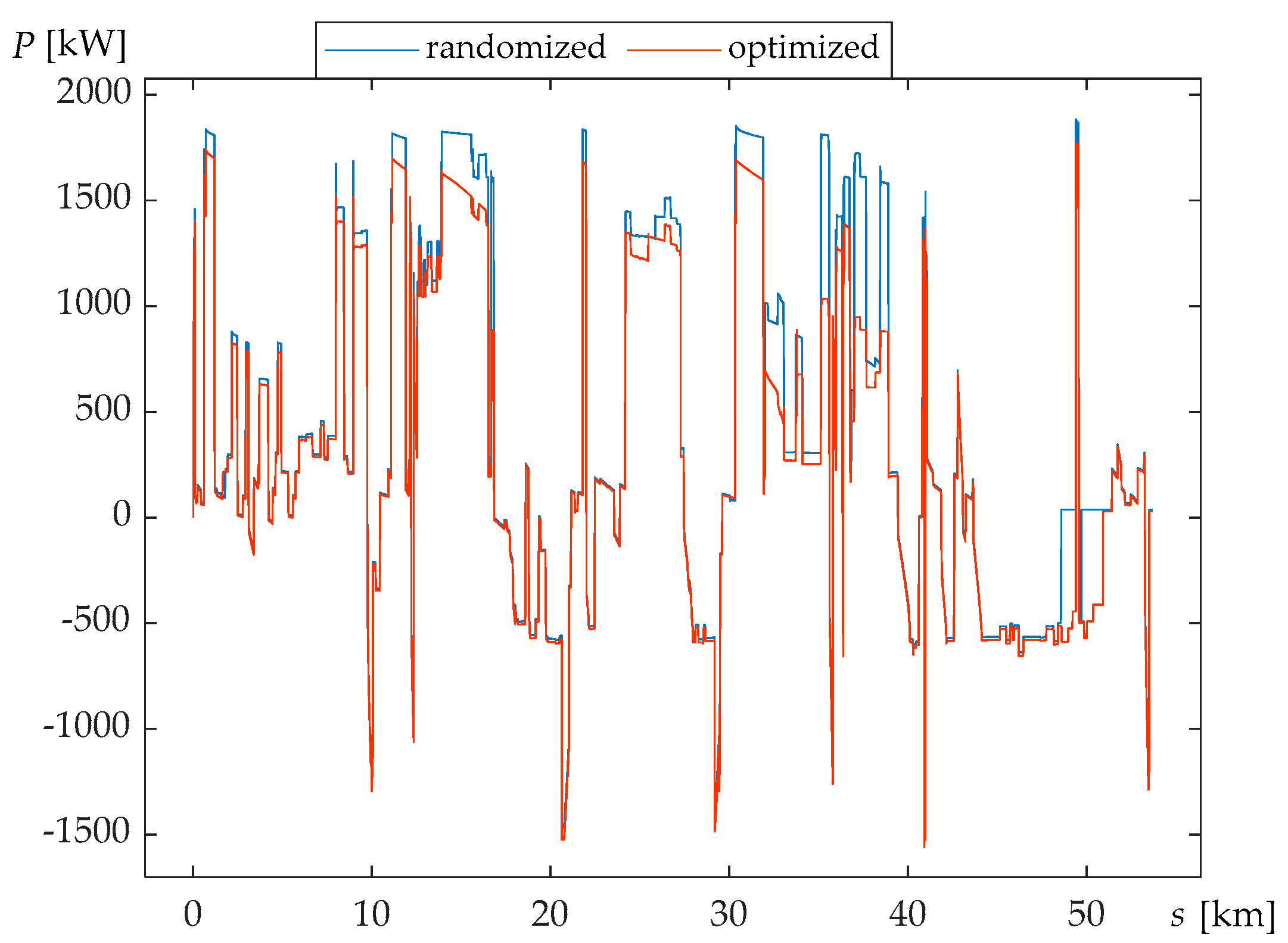
Due to the different losses in the devices, according to the hybridization ratios, the total power of all power sources will not always be the same. Consequently, with the optimal hybridization ratio, a lower required total power to propel the train was achieved. By comparing the required train power on the modeled railway for the initial and optimized drive system, this was revealed during acceleration and regenerative braking (
Figure 11).
According to all losses, the highest power of all power sources is 1772 kW. According to the optimal hybridization ratio, the fuel cell consumes 964 kW. This power requires 7 stacks of fuel cells, which have a total mass of 2828 kg. The fuel cell with 7 stacks has 1050 kW, which means that the rest of the optimal value is used to propel auxiliary devices.
Since the hybridization ratio and discharge current of the battery package are found through optimization, the battery package has a power of 691 kW. The operating voltage of each power source is 800 V, so 243 cells will be connected in series in the battery package. According to the discharge current in the battery package, 52 cells will be connected in parallel. The mass is 960 kg.
The same types of parameters affect the supercapacitor. According to the operating voltage, 296 cells are connected in series in a supercapacitor package. By optimizing the hybridization ratio and the discharge current, the supercapacitor package has a power of 117 kW, and 2 cells are connected in parallel. According to this connection, the mass is 302 kg.
4. Conclusions
This paper presents the development of a hybrid power train system with fuel cells and presents the parameters of each component. A new energy management strategy based on railway loads and the state of charge of the energy storage is proposed. Then, the system was optimized using the SQP method, and the hydrogen consumption was calculated. By optimizing using Matlab/Simulink, it was shown that the mass of the train and the consumption of hydrogen could be reduced.
Because the railway is sharp and demanding, the energy management had to be different than what is usually set. Big uphill transits consume a lot of energy, but traveling downhill can be used for energy regeneration, which is why supercapacitor charging is used when traveling downhill, while the battery is charged via the fuel cell only when the supercapacitor conducts the traction itself. Nevertheless, the simulation showed that the train could overcome such a railway and, at the same time, find the lowest hydrogen consumption with optimal hybridization parameters and discharge currents. The result is a 14.7% decrease in hydrogen fuel consumption and 23.37% less energy consumed.
The current fuel cell systems do not leave much space for optimization. Only by optimally choosing the hybridization ratios of the battery and the supercapacitor can the power of the fuel cell be said to be optimal. The batteries and supercapacitors are delivered in smaller cells, and they give the possibility of optimization.
On the existing train prototype, the total mass of 3 diesel engines and 3 alternators is around 7300 kg. By optimizing the hybrid train with fuel cells, the mass of the power sources (including converters and inverter) was obtained at less than 4091 kg, which indicates that a fuel cell hybrid train is favorable for mass reduction. Therefore, it can be argued that a fuel cell hybrid train can have the same acceleration as a diesel train, which is important in passenger traffic.
The presented simulation model could be a useful tool in the conceptual development phase of future hybrid train propulsion systems and train modifications and shorten the development time of future environmentally friendly railway systems.


