Article

Testing System for PV Grid-Connected Power Condition Systems with Support for Ancillary Services

1
ESTSetúbal, DEE, IPS—Instituto Politécnico de Setúbal, 2910-761 Setúbal, Portugal
2
Sustain.RD, IPS—Instituto Politécnico de Setúbal, 2914-508 Setúbal, Portugal
3
INESC-ID, Lisboa, 1000-029 Lisboa, Portugal
4
ISEL, DEEEA, IPL—Instituto Politécnico de Lisboa, 1959-007 Lisboa, Portugal
5
UNINOVA-CTS, UNL, 2829-516 Caparica, Portugal
6
FCT, DEEC, UNL—Universidade Nova de Lisboa, 2829-516 Caparica, Portugal
7
School of Electrical Engineering, China University of Mining and Technology, Xuzhou 221000, China
*
Author to whom correspondence should be addressed.
Designs 2023, 7(2), 40; https://doi.org/10.3390/designs7020040
Submission received: 12 February 2023 / Revised: 23 February 2023 / Accepted: 2 March 2023 / Published: 4 March 2023
(This article belongs to the Section Energy System Design)

Abstract

:
Due to the high spread of photovoltaic (PV) systems in the low voltage distribution grids there is a substantial number of requirements for the connection of these systems. Therefore, several tests should be performed before the integration of the PV systems into the grid. Moreover, new requirements have been established that are most likely to be implemented in the near future. To provide these tests and verify if PV systems are in accordance with requirements and recommendations, a testing setup for the PV systems was developed. This testing system consists of a controllable power source prepared to receive energy and to inject it into the grid. In fact, that system imposes a controllable voltage, in amplitude and frequency, to the PV system to simulate the perturbations of the grid. Since the system under test must inject energy in accordance with the standards’ specifications, then the controllable power source that emulates the grid must receive that energy. Moreover, it should also be prepared for PV systems that are able to provide ancillary services, including new ones that support imbalanced networks. A fast and robust control system will be used for this controllable power source. Several experimental tests from the developed prototype are presented.

1. Introduction

The importance of producing sustainable electrical energy is nowadays recognized as fundamental due to environmental problems such as global warming and air pollution. The production of electrical energy from renewable energy sources is the path to achieve this desired goal. Among the several renewable energy sources, PV generators are now recognized as one of the most important and with high possibilities of great growth [1,2,3]. However, the integration of the PV generators into the distribution grids requires that their power condition system should take into consideration several issues, such as the ones related with grid injected harmonic currents, other power quality issues, islands and the capability to provide ancillary services [4,5,6]. There are several standards for PV interconnection, the most known being published by the Institute of Electrical and Electronics Engineers (IEEE) and International Electrotechnical Commission (IEC), although several National Standards should also be considered [7]. Under these circumstances PV generators should be subject to extended tests.
The importance of testing the PV generators leads to the development of several types of testing systems. One of these systems is the so-called PV emulator that allows substituting the PV arrays and testing the PV inverter in an easy way for different testing conditions (associated with solar irradiation and temperature). This kind of emulator behaves as a controlled source emulating the PV array characteristic. This controlled source allows emulating the I-V and PV characteristics of a specific PV array considering several ambient factors. There are two types of controlled voltage sources: the linear power amplifier [8,9,10,11,12,13,14] and the switch mode power converter [15,16,17,18,19,20]. One aspect that is critical in these emulators is the use of the PV model that can be more or less complex [21,22,23,24,25,26,27,28]. For example, one aspect that is not considered in many emulators is a model in which the nonlinear dynamic characteristics bias region, in both forward and reverse, is used [29]. Regarding the linear power amplifier, this presents a very high dynamic performance. However, its efficiency is low, being not indicated for medium- and high-power applications. On the other hand, the switch mode power converter presents several advantages, such as high efficiency, high power density and low cost, being indicated for medium- and high-power applications. Another aspect associated with the PV panels testing is regarding arc faults that are one of three major failures in PV systems. Thus, detectors for this kind of fault are required by, for example, the National Electric Code and Underwriters Laboratories standard 1699B. Thus, a testing system for this kind of fault was also proposed [30]. This system was developed specifically for PV systems since this kind of fault is different when compared with AC-system arc fault detectors.
Regarding the test for the PV grid-connected power condition systems, a grid emulator that will allow verifying if the standards and other requirements are met should be used. This grid emulator must be connected, preferably to the grid, in order to transfer the generated active power by the PV array. Several grid emulators have been developed [31,32,33,34]. However, these emulators have been specifically developed to study classical power systems (such as protection relays, industrial equipment and transformers), wind turbines and wave energy converters [35,36,37,38,39,40]. Several types of grid emulators were proposed in the past, namely, the linear power amplifier based, the transformer based and the switch mode power amplifier based. The first one presents a very high dynamic performance, but is very expensive and is characterized by a high volume and weight. The second type (transformer based) is very limitative since only can generate AC voltages with different amplitudes [41]. Regarding the switch mode power amplifier based, it is a very competitive solution since it is characterized by high efficiency, high power density and low cost. However, the opposite of what has been executed regarding the PV emulator, specially developed for PV grid-connected power condition systems, have not been reported. These systems have specific requirements that are not associated with other power system components. In fact, the emulator must be prepared for any kind of PV inverter, both from the point of view of its topology and its control [42,43,44,45,46,47,48,49,50,51]. Moreover, new ancillary services, such as the support to imbalanced networks is expectable in the future, and this has also been considered.
This work seeks to present a testing system specially designed for PV grid-connected power condition systems. The proposed testing system includes a four-wire voltage source inverter in the power conversion stage with the purpose of allowing ancillary services that support imbalanced networks. Additionally, a fast and robust current control system to ensure the desired dynamic response of the testing system is also proposed. In this way, it is ensured that the proposed system is useful to be used as a testing system in real applications. The control system consists of a voltage and current controller to regulate the output voltage of the power converter in the desired reference in a very fast way. A laboratory prototype was developed in this way to test real PV grid-connected power condition systems with support for ancillary services.
Regarding the structure of this paper, it consists of six sections, this one being the introduction. In the second section, the problems related to the connection of a PV system to the grid and the requirements that already exist to avoid that are mentioned. The third section presents the proposed testing systems and the power electronic converters. The control strategy for the power electronic converters used in the proposed testing system are presented in section four. The experimental results obtained with this experimental system are presented in section five. In section six, a discussion of this kind of testing systems is presented. Finally, the conclusions of the work and some perspectives are presented in section seven.

2. Requirements for PV Grid-Connected Power Conditions Systems

Connecting a PV system to the grid may affect the effectiveness of the power system, either in transient mode or on steady state mode. The safe and trusted grid connection of several PV systems remains a huge challenge in today’s modern grid developments and their connection most likely presents side effects that demand particular attention. Amongst others, the effects of connecting PV systems to the grid could include voltage problems, harmonic distortion problems, power factor, DC current injection or island operation [52,53,54]. To further reinforce grid stability and reliability, the European Network of Transmission System Operators for Electricity (ENTSO-E) has defined precise rules that are applicable to all types of grid-connected generators. Typically, grid-connected PV systems are only considered for standard operation under the three following conditions: (a) continuous operation, where they operate at nominal voltage and frequency levels (with some small tolerance); (b) constrained operation, where curtailment or DSO imposed power set points are considered; and (c) disconnection, where they should stop power injection.
There are a huge number of applicable grid codes, and usually those rules differ from country to country, which is a strong barrier regarding grid-connected PV system’s large deployment [55,56,57,58]. The system described in this paper presents the strong advantage of being fully parameterized, thus country-independent, and capable of being used for every grid code in every country.
One important aspect of the grid codes associated to the problem of grid blackouts is due to the fact that power generator systems starts to disconnect under a problem that appears in the grid. To avoid this problem, several grid-code regulations appear with the purpose to maintain renewable energy sources (such as the wind and PV generators) connected to the grid during a specific time when the voltage drops. This specification is usually known as low-voltage ride-through (LVRT). Several countries such as Germany, China and the US among others proposed standards associated with this. Some of the standards that can be referred are the IEEE 1547, GB/T 19964, Q/GDW 617, GB/T 29319 and VDE AR N4105. Another aspect is related to the voltage fluctuation. In this context, there are standards such as IEC 61727 and IEEE 1547 that do not impose a voltage level for PV systems. However, Korea KEPCO Technical Guidelines impose limitations either on the short or long term (less than 4% in 2 s fluctuations). When considering the power factor, the majority of the standards impose a minimum of 0.9. Additionally, as an example, IEC 61727 impose 50% of the PV system nominal power as minimum power to be injected into the grid. Power quality is highly affected by harmonic distortion caused by PV systems. IEC 61727 and IEEE 929 impose a maximum of current distortion for odd harmonics below the 9th order and a maximum of 5% for the total harmonic distortion. Most regulations and connection standards also demand that a PV system detects island situations and stop power injection in those circumstances. IEC 61727 and IEEE 1547 impose 2 s as stop time after island appears, and a maximum of 5 min to reconnect after normal grid conditions are established.
If proper measures are not considered, PV systems inverters could inject a current DC component into the grid, leading, for example, to distribution transformers overheating due to asymmetrical magnetization levels. IEC 61727 imposes a maximum of 1% of the rated output current while IEEE 1547 or IEEE 929 impose a maximum of 0.5%. Voltage imbalance limits are quite different from country to country. Nevertheless, the 2% limit is usually considered. Regarding power imbalance, the German “Power Generating Plants Connected to the Low-voltage Grid” Code of Practice (E VDE-AR-N 4105) [59] considers a maximum of 4.6 kVA of power imbalance between the three phases for a maximum installed power of single phase 10 kVA. Thus, to eliminate or attenuate this problem of imbalance, it has been considered and studied with the implementation of four-wire PV inverters [60]. In this case, it will be possible to inject an imbalanced active power by the PV systems in a way that will compensate the load grid imbalance.

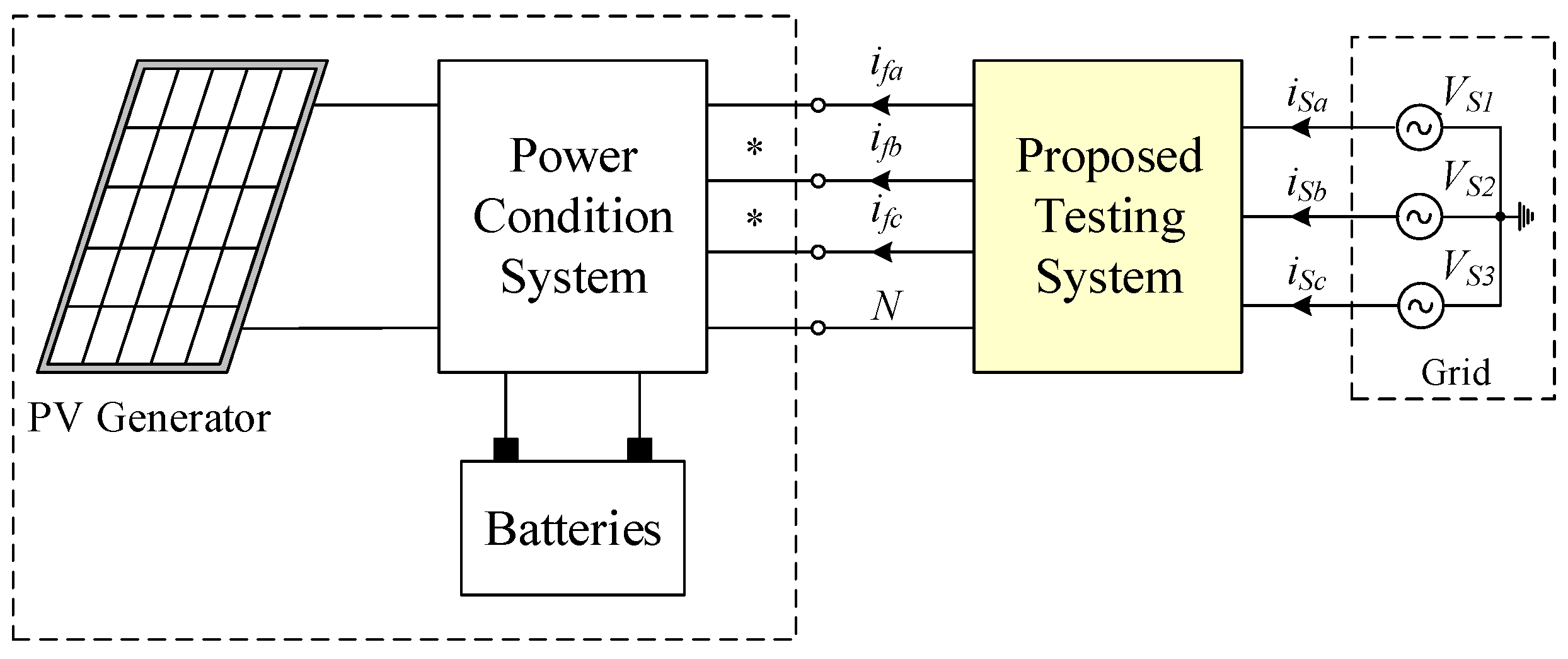
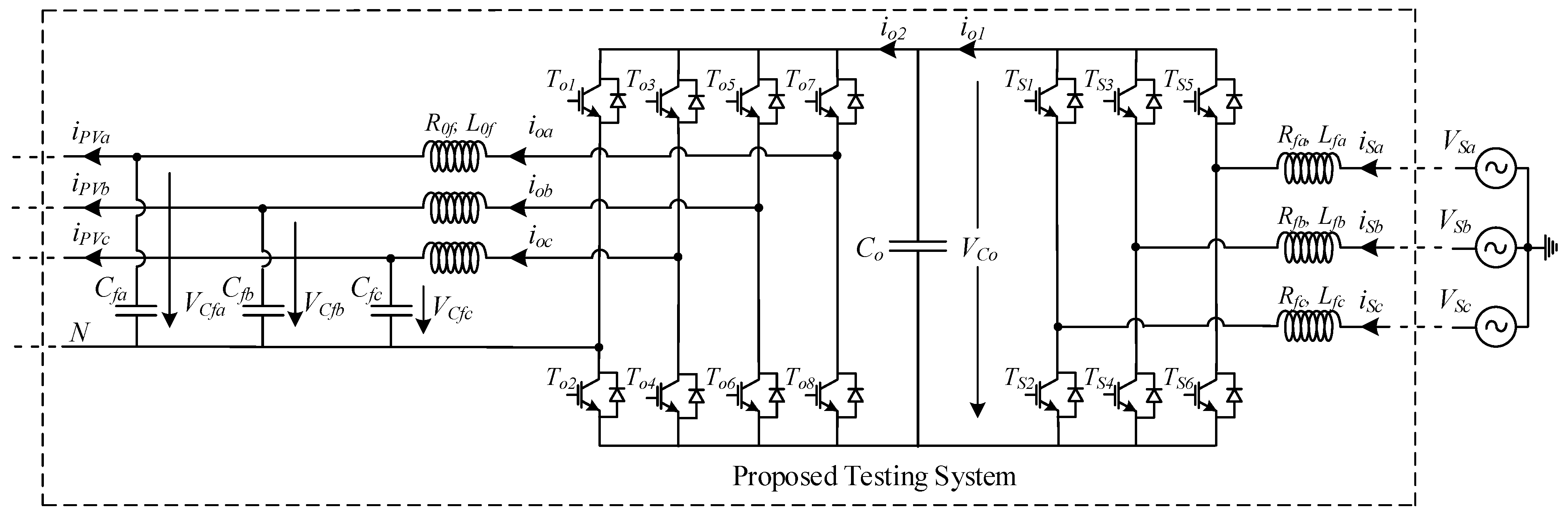
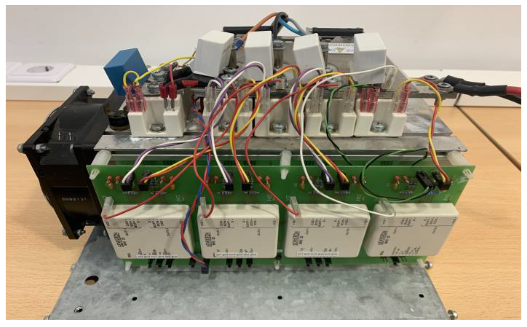
3. Description of the Proposed Testing System

As described in the previous section, there are nowadays many standards that impose or recommend specifications for the PV systems connected to the grid. There are also new recommendations addressing new functions, such as the reactive power control and power factor regulation and the load balance through the injection of imbalanced active and reactive powers. To test PV systems in accordance with those specifications and studies, an adapted testing system was designed. A simplified block diagram of the overall system is presented in Figure 1. The overall system under test consists of PV panels, power condition system (that integrates the MPPT, and DC-AC converter), batteries (optional), testing system and grid. Associated with the testing system, there is a communication module, allowing for connecting the testing system to a computer in order to receive signals and program the required tests.
Regarding the testing system, a Back to Back system was adopted to allow bidirectional energy transfer. For the power converter connected to the grid, a three-leg three-phase voltage source inverter was adopted. However, for the power converter connected to the PV systems, a four-leg three-phase voltage source inverter that allows for testing the system in conditions such as transfer of the energy in an imbalanced way to provide ancillary services such as the support of the imbalanced networks was adopted. A LC low pass filter is connected to the output of this converter. Figure 2 shows the power circuit of the proposed testing system.
The proposed system will be able to test the PV generators even in conditions of imbalance or in a distortion mode; however, it will transfer the energy to the grid in a balanced mode and with a near-unity power factor.

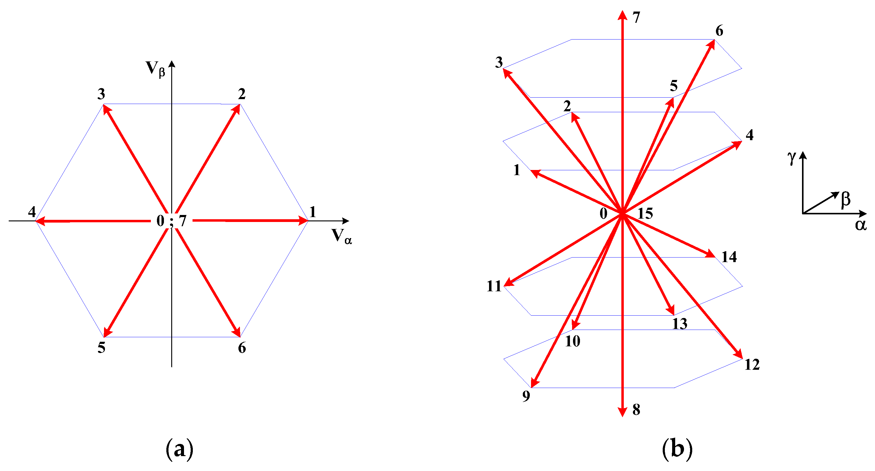
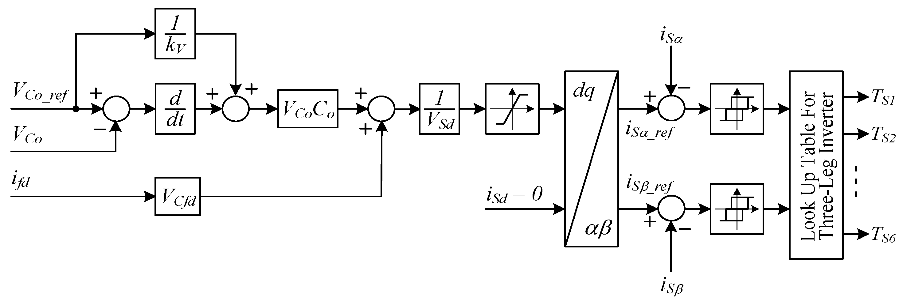
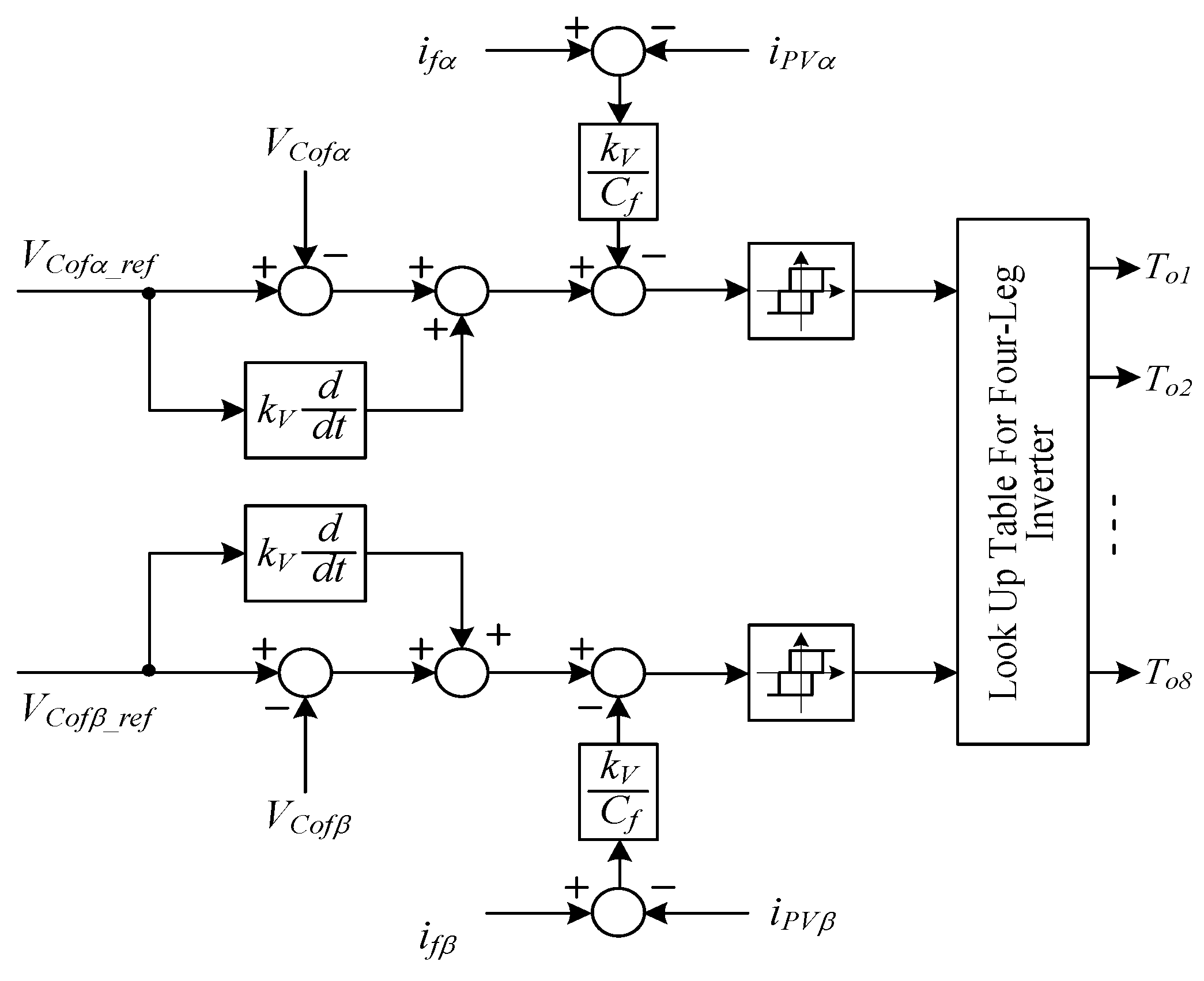
4. Control Strategy for the PV System

As verified in the previous section, the PV testing system must be controlled taking into consideration two sides: the grid side, and the connection to the PV power condition system. Thus, the power converter associated to the grid side (rectifier part) will be controlled with the purpose of regulating the DC voltage bus. The power converter will transfer the energy from or to the grid depending on if the DC voltage is lower or higher than its reference value. On the other hand, the power converter associated to the PV system under test will be controlled in order to behave as a grid in which the parameters could be defined in accordance with the required tests. For the development of the control systems, the mathematical model of the correspondent power circuits is required. Thus, these models are obtained from the state-space equations that allow for describing the dynamic behavior of the testing system. Considering the power circuit of Figure 2, the correspondent displayed state variables and applying Kirchhoff’s voltage law, those equations are:
[ v R a v R b v R c ]   =   [ v S a v S b v S c ]     R f   [ i S a i S b i S c ]     L f   d d t [ i S a i S b i S c ]
[ v C a v C b v C c ]   =   [ v a v b v c ]     R o f   [ i f a i f b i f c ]     L o f   d d t [ i f a i f b i f c ]
d d t [ v C o v C f a v C f b v C f c ]   =   [ 1 C o 0 0 0 0 1 C f 0 0 0 0 1 C f 0 0 0 0 1 C f ]   [ i o 1 i f a i f b i f c ]     [ 1 C o 0 0 0 0 1 C f 0 0 0 0 1 C f 0 0 0 0 1 C f ]   [ i o 2 i P V a i P V b i P V c ]
The pole voltages of each of the converters ( v R a , b , c and v a , b , c ) are functions of the switches’ state and the DC link voltage. These voltages are described by Equations (4) and (5), considering that the switches are represented by binary variables (γ for three-leg converter and δ for four-leg converter), where 1 is for upper switch ON and lower OFF and 0 is for the vice versa condition.
[ v R a v R b v R c ]   =   [ γ a γ b γ c ]   v C o
[ v C a v C b v C c ]   =   [ δ a δ b δ c ]   v C o
For the implementation of the control system, an approach is used that will be based on the αβο coordinates. To develop this control system, taking this into consideration, obtaining the system model in αβο coordinates is required. Hence, the equations of the system in these coordinates (αβο) are given by Equation (6), where Equation (7) is the Clarke-Concordia transform [61].
{ v R α β ,   i S α β   =   T α β   v R a , b , c ,   T α β   i S a , b , c v C α β o ,   i f α β o   =   T α β o   v C a , b , c ,   T α β o   i f a , b , c
T α β o   =   2 3   [ 1 1 2 1 2 0 3 2 3 2 1 2 1 2 1 2 ]
The state-space representation of this system, considering αβο coordinates, will then be given by Equations (8) and (9):
d d t [ i S α i S β i f α i f β v C o ] = [ R f L f 0 0 0 γ α L f 0 R f L f 0 0 γ β L f 0 0 R o f L o f 0 δ α L o f 0 0 0 R o f L o f δ β L o f γ α C o γ β C o δ α C o δ β C o 0 ] [ i S α i S β i f α i f β v C o ]   + [ 1 L o f 0 0 0 0 1 L o f 0 0 0 0 1 L o f 0 0 0 0 1 L o f 0 0 0 0 ] [ v S α v S β v C f α v C f β ]
d d t [ v C f α v C f β ]   =   [ 1 C o f 0 0 1 C o f ] [ i f α i f β ]   [ 1 C o f 0 0 1 C o f ] [ i P V α i P V β ]
In this system, the variables under control are the input currents of the three-leg converter (isa, isb and isc), the capacitor voltage of the DC bus (vCo) and the three-phase capacitor voltages associated to the four-leg converter (vCfa, vCfb, vCfc). However, the reference of the AC currents of the converter connected to the grid (three-leg inverter) will be defined by the controller associated to the DC bus. On the other hand, the controller associated to the PV systems (four-leg inverter) will be independent of the other system to ensure the desirable characteristics that are required for the applied voltage. With the purpose of obtaining a robust controller for the AC voltages and currents, controllers based on the variable structure control are adopted. However, for the activation of the switches of both converters, αβο vectorial modulators will be used (or αβο for the four-leg inverter). Hence, the control equations will be defined in the αβο plane (or αβο for the four-leg inverter). Taking into consideration the state space model of the converters in the controllability canonical form and the feedback errors, the control equations are defined by Equations (10) and (11) [62]:
{ S i s α   =   k i   ( i s α r e f i s α ) S i s β   =   k i   ( i s β r e f i s β )
{ S v C o f α   =   ( v C o f α r e f v C o f α ) + k v ( d v C o f α r e f d t d v C o f α d t ) S v C o f β   =   ( v C o f β r e f v C o f β ) + k v ( d v C o f β r e f d t d v C o f β d t ) S v C o   =   ( v C o r e f v C o ) + k v ( d v C o r e f d t d v C o d t )
From the last control Equation (11) is possible to see that the control is dependent on the derivate of the capacitor voltages. However, under the point of view of a real application, this can be a problem since normally there is noise associated with the acquired signals. Hence, through Kirchhoff’s current law, the derivate of the capacitor voltages could be replaced by the inductor and PV system currents, leading to a new control law as described by Equation (12).
{ S v C o f α   =   ( v C o f α r e f v C o f α ) + k v ( d v C α r e f d t i f α i P V α C f ) S v C o f β   =   ( v C o f β r e f v C o f β ) + k v ( d v C o f β r e f d t i f β i P V β C f ) S v C o   =   ( v C o r e f v C o )   + k v ( d v C o r e f d t γ α i S α + γ β i S α δ α i f α δ β i f β C o )
By the analysis of the control law associated to the control of the DC voltage of the two inverters, a problem related with this nonlinear system is verified. This problem is associated with the sliding function that controls the DC voltage of the two inverters since include the nonlinear terms γα, γβ, δα and δβ. Thus, using a transformation from the referential αβ to the referential dq applying the transform given by Equation (13), a new sliding surface is obtained in accordance with Equation (14) [61].
T d q o   =   [ cos ( θ ) sin ( θ ) 0 sin ( θ ) cos ( θ ) 0 0 0 1 ]
S v C o   =   ( v C o r e f v C o )   + k v ( d v C o r e f d t γ d i S d + γ q i S q δ d i f d δ q i f q C o )
This can be solved considering: (a) the power balance equations are in steady-state, (b) that the converter connected to the grid only exchanges active power, and (c) that the mean value of the capacitor current in steady state is zero. In agreement with these three considerations, the following relationships are obtained:
{ v C o i o 1     v S d i S d + v S q i S q v C o i o 2     v C f d i f d + v C f q i f q γ d i S d + γ q i S q     i o 1 δ q i f d + δ q i f q     i o 2
Using the relationships given by Equation (15) and considering that in the Park rotating reference frame vSq = 0, a new sliding surface associated to the control of the DC voltage of the two inverters will be obtained, as expressed by Equation (16):
S v C o   =   ( v C o r e f v C o ) + k v ( d v C o r e f d t v S d i S d v C f d i f d v C o C o )
Taking into account that the sliding surface must be equal to zero, it will be possible to obtain the current d component that the three-leg inverter must ensure to balance the DC capacitor voltage. This current component will, in this way, be given by Equation (17):
S v C o   =   ( v C o r e f v C o )   + k v ( d v C o r e f d t γ d i S d + γ q i S q δ d i f d δ q i f q C o )
This current component will be used as a reference in the sliding surfaces given by Equation (11). However, since sliding surfaces are defined in the referential αβ, this component and the iSq that will be zero (to ensure that the power absorbed or injected into the grid is only the active) and will be converted to this referential through the inverse of the Clarke-Concordia transform.
To ensure that the variables under control follow the references, the sliding surfaces given by Equations (10) and (12) should be equal to zero. To ensure that those conditions are reached and after that maintained at the sliding surfaces, a reachability condition must be guaranteed. In this way, the conditions that will ensure the reachability condition will be given by Equations (18) and (19) [62]:
S i α ( e i s   α , t ) S i α ( e i s   α , t )   < 0
S i β ( e i s   β , t ) S i β ( e i s   β , t )   < 0
The conditions given by Equations (18) and (19) will be ensured through a vectorial modulator that will choose the state of the switches in order to apply the desired voltage. The AC voltages of the two inverters in αβ and αβο coordinates leads to a diagram in which for the three-leg converter there are eight voltage vectors and sixteen for the four-leg converter. Since the testing system should be prepared to test the PV system for imbalanced tests, for the four-leg converter, in addition to the vectors in the αβ plane, the third dimension given by the o component should also be considered. These vectors are presented in Figure 3.
Taking into consideration converter voltage vectors, it is possible to define conditions to ensure that the trajectory of the sliding surfaces will be in the direction to zero. Consider an example for the three-leg inverter. Assuming, for example, the condition is negative. It should choose a converter voltage vector with a positive α component. For the other component of the sliding surfaces ( S i s β ), the same principle should be applied. For the four-leg inverter, the o component should also be considered, since in this inverter the neutral wire is also considered. The implementation of this strategy will be achieved using proper look-up tables. These look-up tables are function of the signal of the sliding surfaces. However, to limit the switching frequency of the power semiconductors between the look-up tables and the result of the sliding surfaces, hysteretic comparators will be used. Given eight and sixteen voltage vectors for the three-leg and four-leg inverters, respectively, hysteretic comparators with three levels are considered (at which their outputs will by dSiα, dSiβ, dSvα, dSvβ and dSvo that will assume −1, 0 or +1). Thus, the look-up table for the control system of the three-leg inverter will be given by Table 1, while the four-leg inverter will be given by Table 2. The control system for the three-leg inverter and for the four-leg inverter can be seen in Figure 4 and Figure 5, respectively.

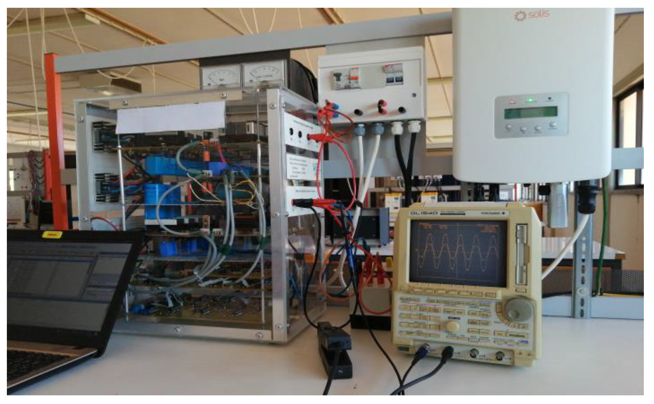
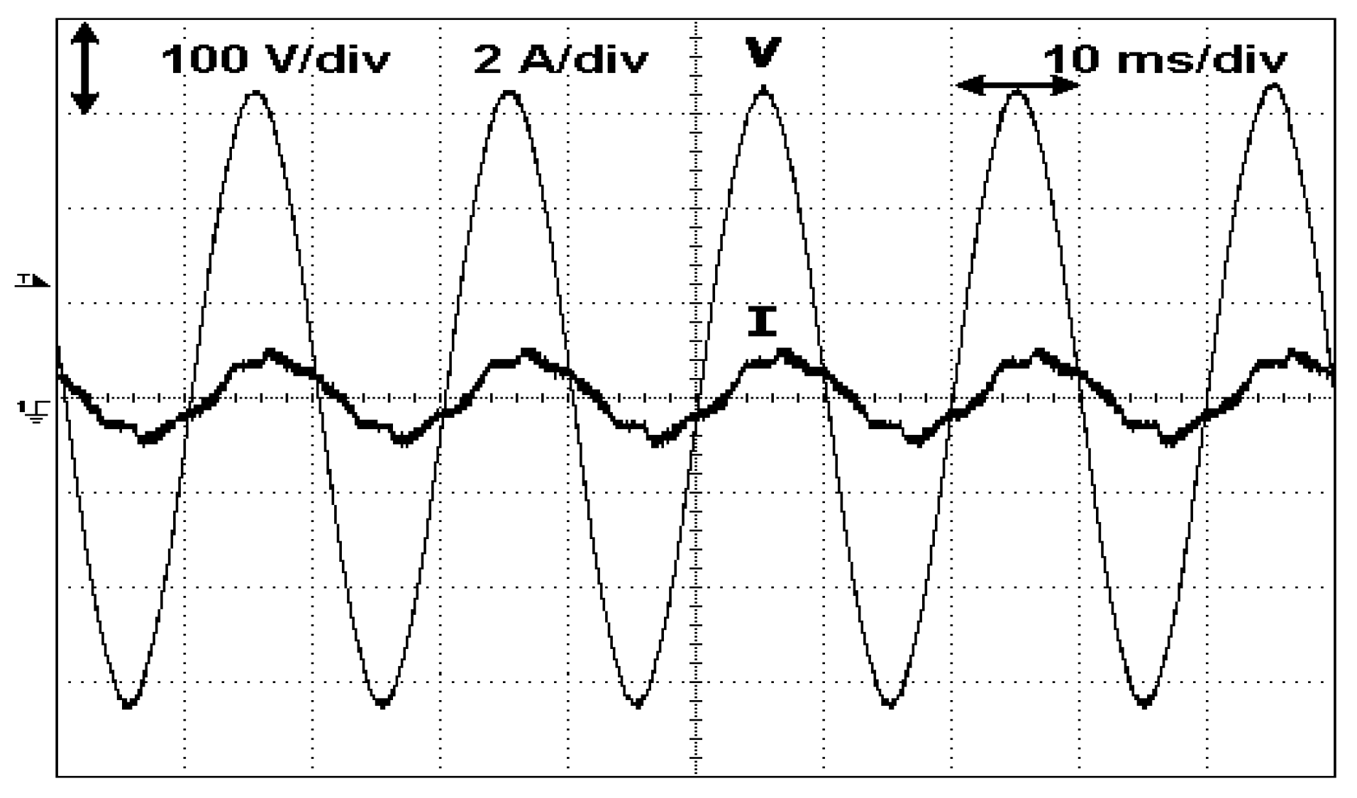
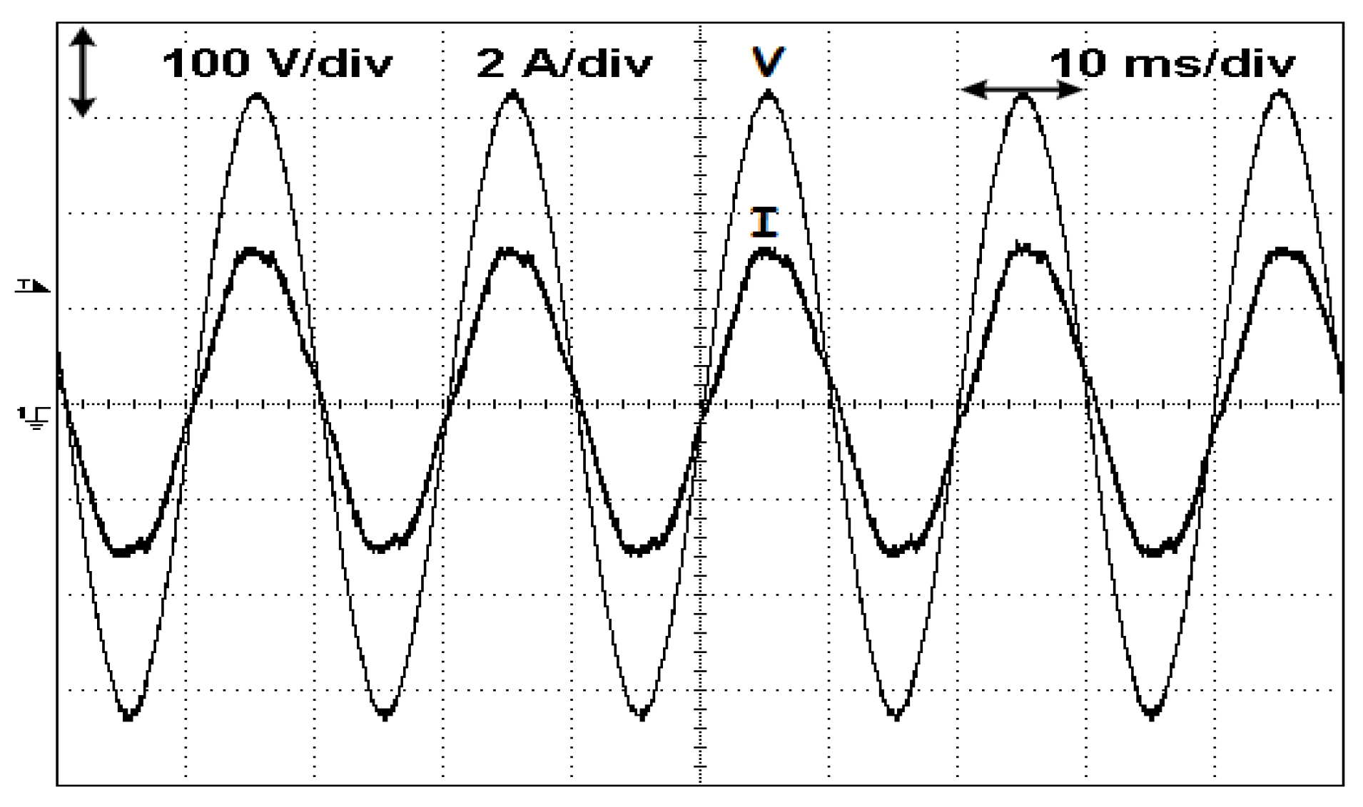
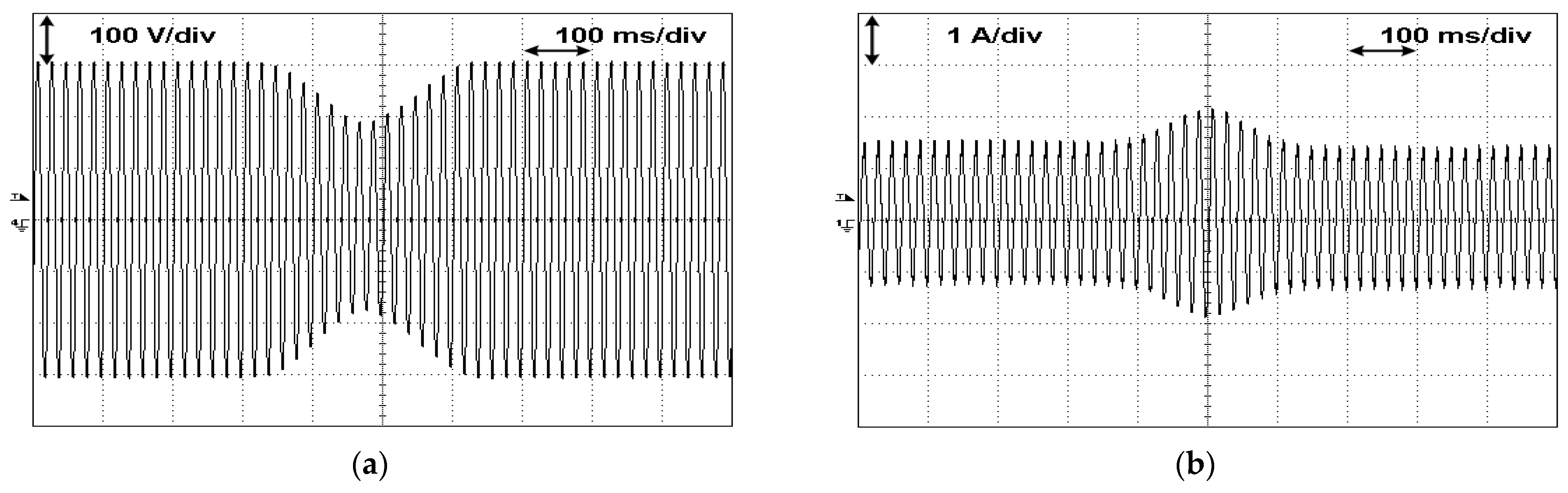
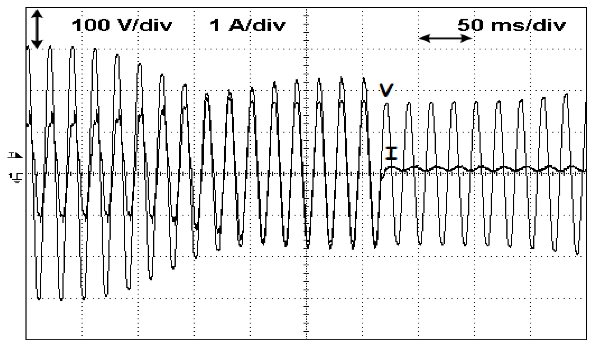
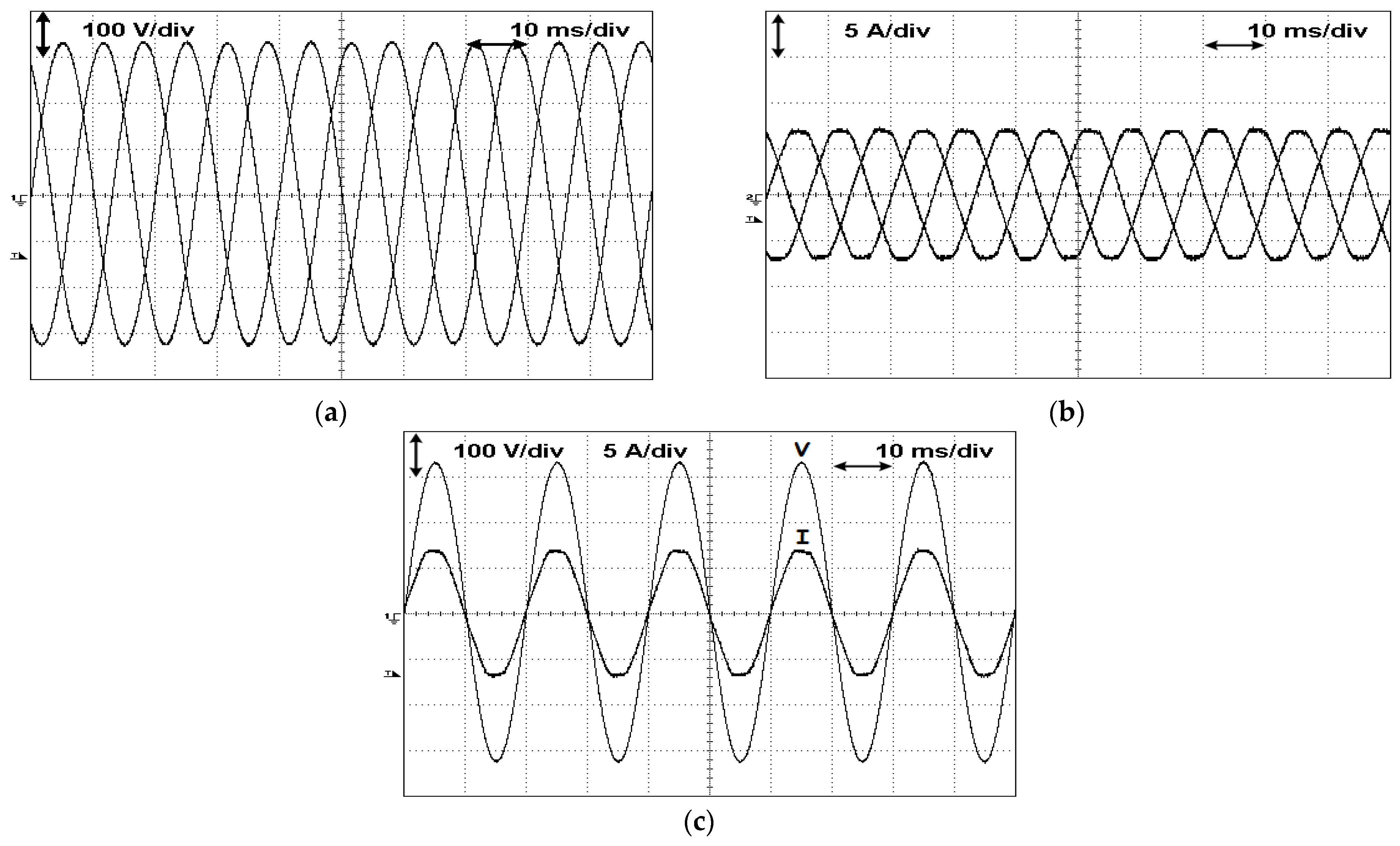
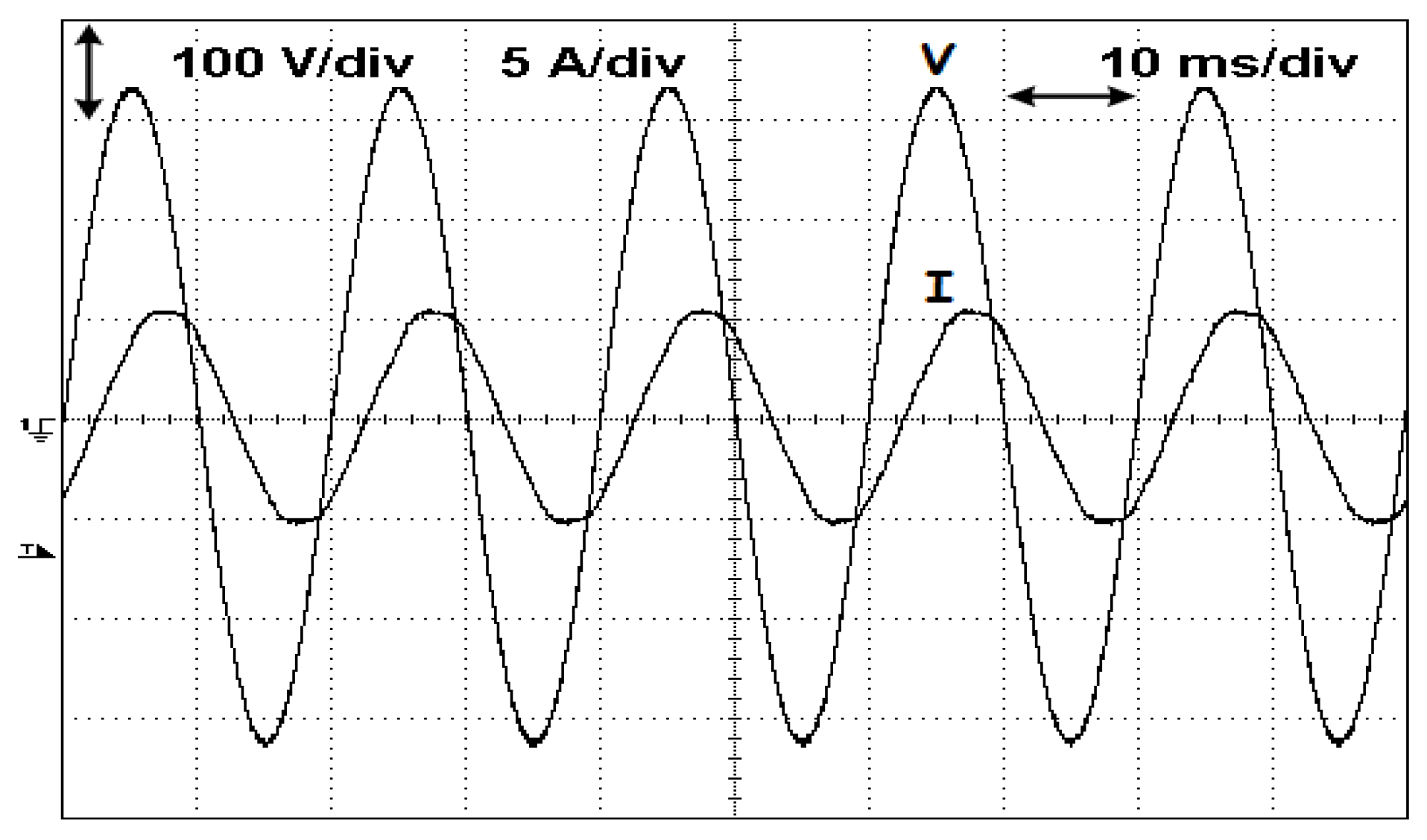
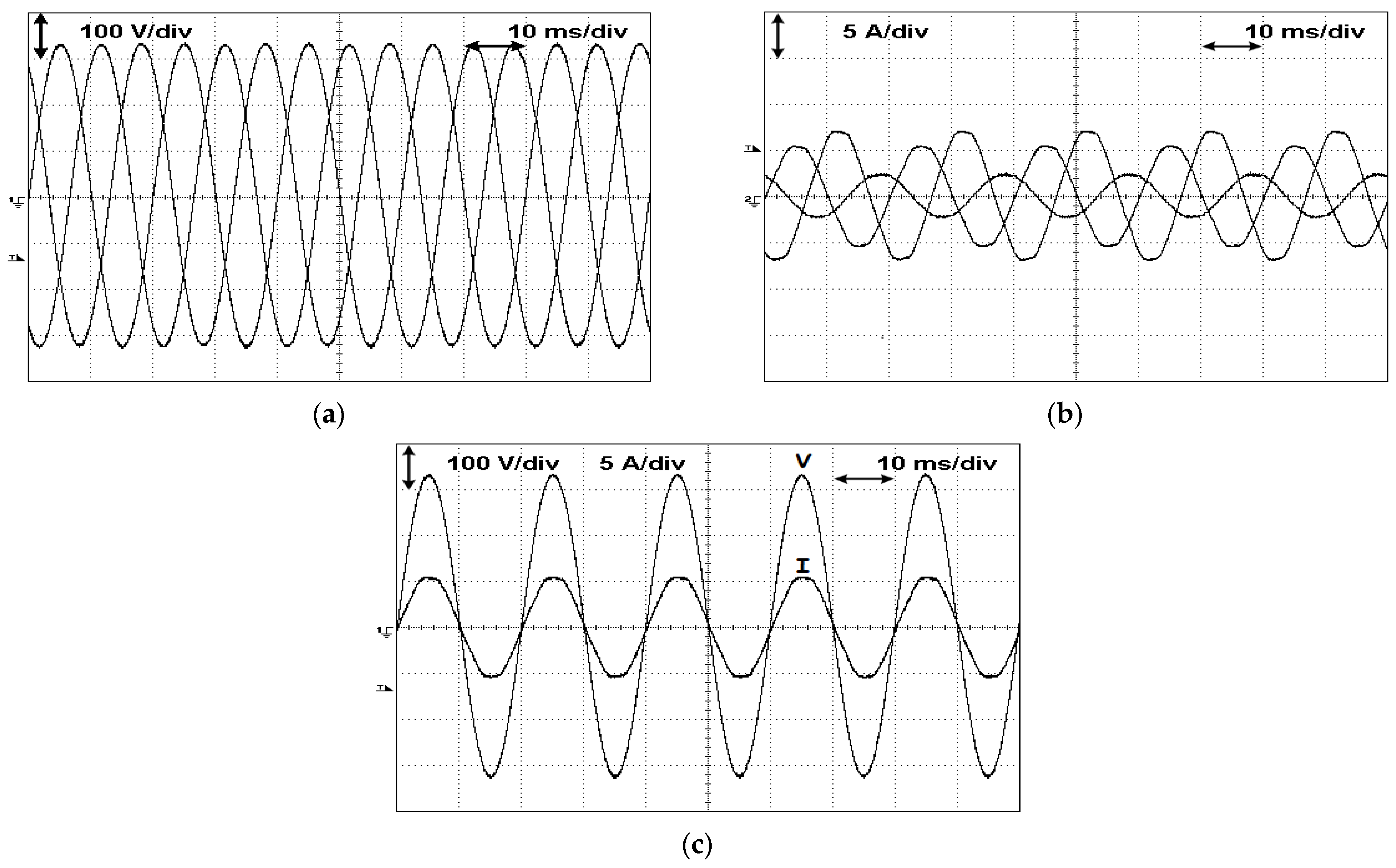
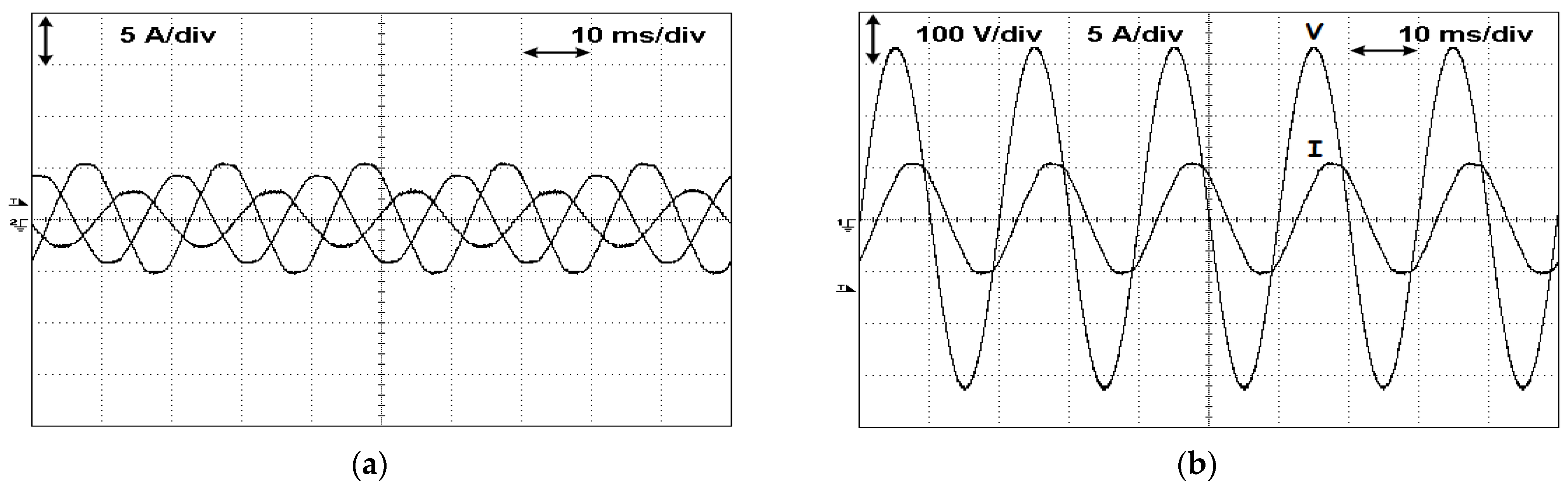
5. Experimental Results

The developed testing system for PV generators (in which the inverters are considered) was tested with different systems. For the implementation of this testing system, IGBT’s CM100DY 24NF, low-pass filters with 10 mH and 10 μF and input inductors with 10 mH were used. Associated to these power electronic converters, a set of low-power components was considered. These components were designed taking into consideration several aspects, such as the galvanic isolation of the control system and the signal distortion between input and output of the electronic devices [63]. In addition to that, it allows connecting to a laptop with the purpose of choosing the test conditions that will be imposed to the PV system under test. This laptop has a program that generates the references for the control system of the power converter and where the user can define the test to be performed. A picture of this testing system is presented in Figure 6. A power quality analyser (Fluke 43B, Fluke Corporation, U.S.) was also used to obtain the values of several parameters, such as active, reactive and apparent power, THD and power factor, among others.
The first results that are presented were obtained from a test with a commercial solar inverter, namely, a Solis mini-1000. It is a single-phase inverter with a rated output power of 1000 W. Four solar panels (Solton SPI 60-250P, Solton Power Inc., Chino, CA, USA) were connected to this inverter. Since the PV inverter is single phase, only two of the terminals of the proposed testing system (L1 and N) were used.
The first test with this commercial solar inverter was performed in steady-state conditions in which the testing system simply applies a single-phase voltage with the nominal value of 230 VRMS. The voltage applied by the testing system and the current injected by the solar inverter into this testing system are presented in Figure 7. One aspect that is possible to see is that the injected current presents some distortion. Measuring the THD of this current a value of 12.6% was executed. Another aspect is that the current is not perfectly in phase with the voltage. This can be confirmed by the power factor of the system that is 0.79 and the displacement power factor of 0.81 (being the active, reactive and apparent powers of 107 W, 82 VAR and 135 VA, respectively). In this way, the inverter is not only injecting active power but also reactive power. However, when the injected power increases, the THD and reactive power reduces. In Figure 8, the voltage applied by the testing system and the current injected by the solar inverter into this testing system is presented again, but for a higher power (the injected power from the PV generator changed from 135 VA to 508 VA). The power factor and the displacement power factor increases to 0.99 (being the active, reactive and apparent powers of 503 W, 71 VAR and 508 VA, respectively). The THD also was reduced from 12.6% to 4.6%. This shows that the tested PV inverter presents a low-power quality when it operates at low-power conditions.
Other tests that were performed with this commercial system addressed voltage sags and MPPT operation. A voltage sag of 35% was applied by the testing system to the PV system, as presented in Figure 9a. The current injected from the PV system to the testing system is presented in Figure 9b. It is possible to see that the PV system is immune to this type of voltage sag. Moreover, the operation of the MPPT is confirmed, since the PV system maintains the value of the injected power (with the reduction in the voltage, the current increases). However, for voltage sags with higher percentage, the system will disconnect. In Figure 10, a test is presented in which the PV testing system started with a voltage with a nominal value and this value was reduced until the PV inverter disconnects. From this result, it is possible to confirm that for voltage sags higher than 50%, the inverter will disconnect from the grid.
Tests with a three-phase PV inverter with four legs were also performed. This system, presented in Figure 11, was developed in the context of a European Project. The purpose of this PV inverter was also to give support to low-voltage grids with imbalanced loads.
The first tests with this three-phase PV inverter were performed for grid-balanced conditions. In accordance with the performed tests, the three-phase power supplied from the PV inverter to the grid (testing system) is balanced. The three-phase voltages that the testing system imposes on the PV inverter are presented in Figure 12a. On the other hand, the three-phase currents of the PV inverter are shown in Figure 12b. From those obtained results, it is possible to see that the voltages imposed by the testing system and currents injected by the PV inverter are balanced. The THD of the currents is also low, with a value of 4.3%. Another important parameter is the power factor that presents a very high value of 0.99 (in this test, the PV inverter was set to only inject active power to the grid). This high power factor can also be confirmed by the result shown in Figure 12c, in which the voltage and current in phase L1 of the testing system are presented.
One of the ancillary services that has been considered important is the possibility of the PV inverter supplying reactive power in order to give support to grids suffering from voltage drop conditions [64]. The inverter under test was designated to provide this service, being the developed testing system used to test this capability. The obtained results in this test can be seen in Figure 13. The voltage and current in phase L1 of the testing system that are presented in Figure 13 show that the current is shifted from the voltage with an angle of around 45°. This confirms that the PV inverter is injecting active and reactive power.
A test in which the PV inverter provides ancillary services associated to low-voltage grids with imbalanced loads was also performed. In this case, the PV inverter operates in a way that injects imbalanced currents to the grid (testing system). In this way, the capability of the PV inverter to provide ancillary services to networks with imbalanced loads was tested. The results of this test are shown in Figure 14. From this figure, it is possible to see that although the voltages that the testing system applies are balanced, the injected currents from the PV inverter are imbalanced. This test was performed for a condition in which the PV inverter does not provide reactive power. This can be confirmed through Figure 14a, where it is possible to see the near-unity power factor operation. This inverter was tested again for the condition of injecting imbalanced currents, but in this case compensating also reactive loads. Figure 15 shows the waveforms of the three phase currents injected into the testing system and voltage and current of phase L1. Through their analysis, it is possible to confirm that the currents are imbalanced and that they are not in phase anymore. It is possible to confirm the active and reactive compensation of the imbalanced loads.

6. Discussion

Due to the importance of the PV generators in the actual context of the renewable energy sources, the criteria to interconnect them into the electrical grid increases constantly. Thus, these kind of generators should be tested before their integration into the grid. Those tests must be in accordance with the applicable grid codes that exist in different countries. In fact, those rules usually differ from country to country, which is a strong barrier regarding grid-connected PV systems’ large deployment. Nowadays, there are already testing systems for PV generators. However, they only allow for testing the generators for the existing applicable grid codes, and they are not adapted for new grid codes that can appear in the future or requirements from specific clients. This is the case of testing the PV inverters that allows giving support to the network under the perspective of the balance of low-voltage networks with neutral wire. For this kind of tests, there is the need for a testing system that supports a four-wire connection for the PV inverter. However, this is not the standard in the industry, since they typically only allow for a three-wire connection. Thus, this work proposes a solution that can be used in the future by the industry, based on classical converters such as the H-bridge inverters which allow for developing a low-cost testing system. This is an important aspect for a future industry application. In Table 3, several types of equipment can be seen that have already been developed for PV generators. As shown in that table, there are several different pieces of equipment that have been developed for this system. However, each of them is designed for a specific test, since there are different aspects that need to be tested. Nevertheless, one piece of test equipment that was not developed was for the test of the PV inverter, taking into consideration their capability to provide ancillary services requiring a neutral connection. Another important aspect is the control of the testing system. Many times, the controller presents a low dynamic, which could affect the test of the PV inverter under, for example, fast perturbations. This work also tried to focus on this. Finally, another aspect that is also important is that with the implementation of PV generators, new grid codes could appear in the near future. Thus, the testing system should be flexible enough to allow the implementation of tests taking into consideration these new grid codes. This is an aspect not considered in this work, since its purpose was more to have an approach under the perspective of the hardware of the testing system. Nevertheless, the software is also an important part that needs many resources.

7. Conclusions

In this work, the design of a testing setup for grid-connected PV systems was presented and described. This setup was developed taking into consideration the last requirements and recommendations for the integration of PV systems in distribution grids (micro and smart grids frameworks). In this context, the standards and recommendations for the referred integrations were presented and considered. In accordance with those specifications, a controllable power source prepared to receive energy, as well as to inject it into the grid, was developed for the testing system. The capability of injecting energy into the grid has the purpose of testing PV systems with storage devices. The power converters of the system allow for imposing a controllable voltage, in amplitude and frequency, to the PV system. In this way, it will be possible to simulate the perturbations of the grid. Two power converters were used, namely a four-leg voltage source inverter with an LC filter to connect to the PV system and a three-phase power factor corrector connected to the grid. To choose the test that will be imposed to the PV system, the setup is connected to a laptop. In this laptop, there is a program that generates the references for the control system of the power converter and in which the user defines the test to be performed. Several experimental tests were obtained, in which a commercial solar inverter and a PV generator developed in the context of a European project, were used. The results showed the characteristics and capabilities of the developed testing system. Due to those capabilities, it was possible to verify that the setup gives an easy and flexible way to test PV systems in accordance with the latest requirements and recommendations. One aspect not considered in the work is the software, since the purpose was more to have an approach under the perspective of the hardware of the testing system. However, the software is also an important part due to the fact that in the near future, new grid codes could appear. In this way, a perspective of further research is the development of the components’ software, especially taking into consideration the possibility of testing the PV generators under new grid codes that eventually could appear.

Author Contributions

Conceptualization, V.F.P., H.C. and J.F.M.; methodology, V.F.P. and H.C.; simulations, V.F.P. and J.F.M.; validation, V.F.P., D.F., A.C. and A.P.; formal analysis, V.F.P. and J.F.M.; investigation, V.F.P.; resources, V.F.P.; data curation, V.F.P.; writing—original draft preparation V.F.P., D.F. and A.C.; writing—review and editing, A.P. and A.C.; visualization, A.P. and A.C.; supervision, A.P.; project administration, J.F.M.; funding acquisition, A.P. and J.F.M. All authors have read and agreed to the published version of the manuscript.

Funding

This work was supported by national funds through FCT—Fundação para a Ciência e a Tecnologia with reference UID/CEC/50021/2020 and UID/EEA/00066/2020.

Data Availability Statement

Not applicable.

Acknowledgments

This work was supported by national funds through FCT—Fundação para a Ciência e a Tecnologia with reference UID/CEC/50021/2020 and UID/EEA/00066/2020.

Conflicts of Interest

The authors declare no conflict of interest.

References

  1. Gielen, D.; Boshell, F.; Saygin, D.; Bazilian, M.D.; Wagner, N.; Gorini, R. The role of renewable energy in the global energy transformation. Energy Strategy Rev. 2019, 40, 38–50. [Google Scholar] [CrossRef]
  2. International Energy Agency. Renewables 2022: Analysis and Forecasts to 2027. Available online: https://www.iea.org/reports/renewables-2022 (accessed on 6 February 2023).
  3. Rehman, A.; Radulescu, M.; Cismas, L.M.; Alvarado, R.; Secara, C.G.; Tolea, C. Urbanization, Economic Development, and Environmental Degradation: Investigating the Role of Renewable Energy Use. Sustainability 2022, 14, 9337. [Google Scholar] [CrossRef]
  4. Strasser, T.; Andrén, F.; Kathan, J.; Cecati, C.; Buccella, C.; Siano, P.; Leitão, P.; Zhabelova, G.; Vyatkin, V.; Vrba, P. A Review of Architectures and Concepts for Intelligence in Future Electric Energy Systems. IEEE Trans. Ind. Electron. 2015, 62, 2424–2438. [Google Scholar] [CrossRef] [Green Version]
  5. Kavya Santhoshi, B.; Mohana Sundaram, K.; Padmanaban, S.; Holm-Nielsen, J.B. Critical Review of PV Grid-Tied Inverters. Energies 2019, 12, 1921. [Google Scholar] [CrossRef] [Green Version]
  6. Gupta, N.; Dogra, R.; Garg, R.; Kumar, P. Review of islanding detection schemes for utility interactive solar photovoltaic systems. Int. J. Green Energy 2022, 19, 242–253. [Google Scholar] [CrossRef]
  7. Rangarajan, S.S.; Collins, E.R.; Fox, J.C.; Kothari, D.P. A survey on global PV interconnection standards. In Proceedings of the IEEE Power and Energy Conference at Illinois (PECI), Champaign, IL, USA, 23–24 February 2017; pp. 1–8. [Google Scholar]
  8. Jin, S.; Zhang, D.; Bao, Z.; Liu, X. High Dynamic Performance Solar Array Simulator Based on a SiC MOSFET Linear Power Stage. IEEE Trans. Power Electron. 2018, 33, 1682–1695. [Google Scholar] [CrossRef]
  9. Moussa, I.; Khedher, A.; Bouallegue, A. Design of a Low-Cost PV Emulator Applied for PVECS. Electronics 2019, 8, 232. [Google Scholar] [CrossRef] [Green Version]
  10. Sanaullah, S.; Khan, H.A. Design and implementation of a low cost Solar Panel emulator. In Proceedings of the IEEE 42nd Photovoltaic Specialist Conference (PVSC), New Orleans, LA, USA, 14–19 June 2015; pp. 1–5. [Google Scholar]
  11. Korasiak, P.; Jaglarz, J.A. New Photovoltaic Emulator Designed for Testing Low-Power Inverters Connected to the LV Grid. Energies 2022, 15, 2646. [Google Scholar] [CrossRef]
  12. Ahmed, M.; Harbi, I.; Kennel, R.; Abdelrahem, M. Maximum Power Point Tracking Implementation under Partial Shading Conditions Using Low-Cost Photovoltaic Emulator. Energy 2022, 3, 424–438. [Google Scholar] [CrossRef]
  13. Chen, C.-C.; Chang, H.-C.; Kuo, C.-C.; Lin, C.-C. Programmable energy source emulator for photovoltaic panels considering partial shadow effect. Energy 2013, 54, 174–183. [Google Scholar] [CrossRef]
  14. Merenda, M.; Iero, D.; Carotenuto, R.; Della Corte, F.G. Simple and Low-Cost Photovoltaic Module Emulator. Electronics 2019, 8, 1445. [Google Scholar] [CrossRef] [Green Version]
  15. Prasanth Ram, J.; Manghani, H.; Dhanup, S.; Pillai, T.; Babu, S.; Miyatake, M.; Rajasekar, N. Analysis on solar PV emulators: A review. Renew. Sustain. Energy Rev. 2018, 81, 149–160. [Google Scholar]
  16. Schofield, D.M.K.; Foster, M.P.; Stone, D.A. Low-cost solar emulator for evaluation of maximum power point tracking methods. Electron. Lett. 2011, 47, 208–209. [Google Scholar] [CrossRef]
  17. Ma, C.-T.; Tsai, Z.-Y.; Ku, H.-H.; Hsieh, C.-L. Design and Implementation of a Flexible Photovoltaic Emulator Using a GaN-Based Synchronous Buck Converter. Micromachines 2021, 12, 1587. [Google Scholar] [CrossRef]
  18. Jayawardana, I.D.G.; Ho, C.N.M.; Pokharel, M.; Valderrama, G.E. A Fast-Dynamic Control Scheme for a Power-Electronics-Based PV Emulator. IEEE J. Photovolt. 2021, 11, 485–495. [Google Scholar] [CrossRef]
  19. Ayop, R.; Tan, C.W. Rapid Prototyping of Photovoltaic Emulator Using Buck Converter Based on Fast Convergence Resistance Feedback Method. IEEE Trans. Power Electron. 2019, 34, 8715–8723. [Google Scholar] [CrossRef]
  20. Cordeiro, A.; Foito, D.; Pires, V.F. A PV panel simulator based on a two quadrant DC/DC power converter with a sliding mode controller. In Proceedings of the International Conference on Renewable Energy Research and Applications, Palermo, Italy, 22–25 November 2015; pp. 928–932. [Google Scholar]
  21. Premkumar, M.; Jangir, P.; Sowmya, R.; Rajvikram Elavarasan, M.; Kumar, B.S. Enhanced chaotic JAYA algorithm for parameter estimation of photovoltaic cell/modules. ISA Trans. 2021, 116, 139–166. [Google Scholar] [CrossRef] [PubMed]
  22. Batzelis, E. Non-Iterative Methods for the Extraction of the Single-Diode Model Parameters of Photovoltaic Modules: A Review and Comparative Assessment. Energies 2019, 12, 358. [Google Scholar] [CrossRef] [Green Version]
  23. Shinde, U.K.; Kadwane, S.G.; Gawande, S.P.; Keshri, R. Solar PV emulator for realizing PV characteristics under rapidly varying environmental conditions. In Proceedings of the IEEE International Conference on Power Electronics, Drives and Energy Systems, Trivandrum, India, 14–17 December 2016; pp. 1–5. [Google Scholar]
  24. Fahim, S.R.; Hasanien, H.M.; Turky, R.A.; Aleem, S.H.E.A.; Ćalasan, M. A Comprehensive Review of Photovoltaic Modules Models and Algorithms Used in Parameter Extraction. Energies 2022, 15, 8941. [Google Scholar] [CrossRef]
  25. Raya-Armenta, J.M.; Ortega, P.R.; Bazmohammadi, N.; Spataru, S.V.; Vasquez, J.C.; Guerrero, J.M. An Accurate Physical Model for PV Modules with Improved Approximations of Series-Shunt Resistances. IEEE J. Photovolt. 2021, 11, 699–707. [Google Scholar] [CrossRef]
  26. Kihal, A.; Krim, F.; Laib, A.; Talbi, B.; Afghoul, H. An improved MPPT scheme employing adaptive integral derivative sliding mode control for photovoltaic systems under fast irradiation changes. ISA Trans. 2019, 87, 297–306. [Google Scholar] [CrossRef]
  27. Villalva, M.G.; Gazoli, J.R.; Filho, E.R. Comprehensive Approach to Modeling and Simulation of Photovoltaic Arrays. IEEE Trans. Power Electron. 2009, 24, 1198–1208. [Google Scholar] [CrossRef]
  28. Sheikhipour, S.; Ghadimi, A.A.; Mirzaei, A. A sensor-less control and optimal energy management algorithm for a stand-alone photovoltaic system considering partial shading condition. ISA Trans. 2021, 128, 606–623. [Google Scholar] [CrossRef] [PubMed]
  29. Mahmoud, Y.; Xiao, W.; Zeineldin, H.H. A Simple Approach to Modeling and Simulation of Photovoltaic Modules. IEEE Trans. Sustain. Energy 2012, 3, 185–186. [Google Scholar] [CrossRef]
  30. Ameen, R.; Abdulmawjood, K.; Abbas, S.; Shukri, S.; Khraisheh, K.; Alpuerto, L.; Balog, R.S. Mechatronics Arc Generator for Photovoltaic Arc Fault Detector Testing. In Proceedings of the IEEE 46th Photovoltaic Specialists Conference (PVSC), Chicago, IL, USA, 16–21 June 2019; pp. 1306–1311. [Google Scholar] [CrossRef]
  31. Kim, K.A.; Xu, C.; Jin, L.; Krein, P.T. A Dynamic Photovoltaic Model Incorporating Capacitive and Reverse-Bias Characteristics. IEEE J. Photovolt. 2013, 3, 1334–1341. [Google Scholar] [CrossRef]
  32. Vogel, S.; Nguyen, H.T.; Stevic, M.; Jensen, T.V.; Heussen, K.; Rajkumar, V.S.; Monti, A. Distributed Power Hardware-in-the-Loop Testing Using a Grid-Forming Converter as Power Interface. Energies 2020, 13, 3770. [Google Scholar] [CrossRef]
  33. Si, G.; Cordier, J.; Kennel, R.M. Extending the Power Capability with Dynamic Performance of a Power-Hardware-in-the-Loop Application-Power Grid Emulator Using Inverter Cumulation. IEEE Trans. Ind. Appl. 2016, 52, 3193–3202. [Google Scholar] [CrossRef]
  34. Hildebrandt, N.; Luo, M.; Dujic, D. Robust and Cost-Effective Synchronization Scheme for a Multicell Grid Emulator. IEEE Trans. Ind. Electron. 2021, 68, 1851–1859. [Google Scholar] [CrossRef]
  35. Wang, J.; Yang, L.; Ma, Y.; Wang, J.; Tolbert, L.M.; Wang, F.; Tomsovic, K. Static and dynamic power system load emulation in a converter-based reconfigurable power grid emulator. IEEE Trans. Power Electron. 2016, 31, 3239–3251. [Google Scholar] [CrossRef]
  36. Ahmad, Z.; Torres, J.R.; Kumar, V.N.; Rakhshani, E.; Palensky, P.; Meijden, M. A Power Hardware-in-the-Loop Based Method for FAPR Compliance Testing of the Wind Turbine Converters Control. Energies 2020, 13, 5203. [Google Scholar] [CrossRef]
  37. Pires, V.F.; Martins, L.S.; Amaral, T.G.; Marçal, R.; Rodrigues, R.; Crisóstomo, M.M. Distance Learning Power System Protection Based on Testing Protective Relays. IEEE Trans. Ind. Electron. 2008, 55, 2433–2438. [Google Scholar] [CrossRef]
  38. Collins, E.R.; Morgan, R.L. A three-phase sag generator for testing industrial equipment. IEEE Trans. Power Deliv. 1996, 11, 526–532. [Google Scholar] [CrossRef]
  39. Bielemeier, J.; Frehn, A.; Monti, A.; Frühmann, R.; Santjer, F. Comparison of multi-megawatt LVRT testing setups for the certification of wind turbines. In Proceedings of the IEEE Milan PowerTech, Milan, Italy, 23–27 June 2019; pp. 1–6. [Google Scholar]
  40. Mesbah, M.; Moses, P.S.; Islam, S.M.; Masoum, M.A.S. Digital Implementation of a Fault Emulator for Transient Study of Power Transformers Used in Grid Connection of Wind Farms. IEEE Trans. Sustain. Energy 2014, 5, 646–654. [Google Scholar] [CrossRef]
  41. Biligiri, K.; Harpool, S.; Jouanne, A.; Amon, E.; Brekken, T. Grid emulator for compliance testing of Wave Energy Converters. In Proceedings of the IEEE Conference on Technologies for Sustainability, Portland, OR, USA, 24–26 July 2014; pp. 30–34. [Google Scholar]
  42. Zeb, K.; Uddin, W.; Adil Khan, M.; Ali, Z.; Umair Ali, M.; Christofides, N.; Kim, H.J. A comprehensive review on inverter topologies and control strategies for grid connected photovoltaic system. Renew. Sustain. Energy Rev. 2018, 94, 1120–1141. [Google Scholar] [CrossRef]
  43. Mohamed Hariri, M.H.; Mat Desa, M.K.; Masri, S.; Mohd Zainuri, M.A.A. Grid-Connected PV Generation System—Components and Challenges: A Review. Energies 2020, 13, 4279. [Google Scholar] [CrossRef]
  44. Fernão Pires, V.; Cordeiro, A.; Foito, D.; Pires, A.J.; Hao, C.; Martins, J.F.; Castro, R. Compensation of Unbalanced Low-Voltage Grids Using a Photovoltaic Generation System with a Dual Four-Leg, Two-Level Inverter. Electronics 2022, 11, 320. [Google Scholar] [CrossRef]
  45. Shahparasti, M.; Savaghebi, M.; Adabi, E.; Ebel, T. Dual-Input Photovoltaic System Based on Parallel Z-Source Inverters. Designs 2020, 4, 51. [Google Scholar] [CrossRef]
  46. Ali Khan, M.Y.; Liu, H.; Yang, Z.; Yuan, X. A Comprehensive Review on Grid Connected Photovoltaic Inverters, Their Modulation Techniques, and Control Strategies. Energies 2020, 13, 4185. [Google Scholar] [CrossRef]
  47. Hassan, Z.; Amir, A.; Selvaraj, J.; Rahim, N.A. A review on current injection techniques for low-voltage ride-through and grid fault conditions in grid-connected photovoltaic system. Sol. Energy 2020, 207, 851–873. [Google Scholar] [CrossRef]
  48. Ahmed, M.; Harbi, I.; Kennel, R.; Rodríguez, J.; Abdelrahem, M. Evaluation of the Main Control Strategies for Grid-Connected PV Systems. Sustainability 2022, 14, 11142. [Google Scholar] [CrossRef]
  49. Verbytskyi, I.; Lukianov, M.; Nassereddine, K.; Pakhaliuk, B.; Husev, O.; Strzelecki, R.M. Power Converter Solutions for Industrial PV Applications—A Review. Energies 2022, 15, 3295. [Google Scholar] [CrossRef]
  50. Haq, S.; Biswas, S.P.; Hosain, M.K.; Rahman, M.A.; Islam, M.R.; Jahan, S. A Modular Multilevel Converter with an Advanced PWM Control Technique for Grid-Tied Photovoltaic System. Energies 2021, 14, 331. [Google Scholar] [CrossRef]
  51. Medina-García, J.; Martín, A.D.; Cano, J.M.; Gómez-Galán, J.A.; Hermoso, A. Efficient Wireless Monitoring and Control of a Grid-Connected Photovoltaic System. Appl. Sci. 2021, 11, 2287. [Google Scholar] [CrossRef]
  52. Zeb, K.; Islam, S.U.; Khan, I.; Uddin, W.; Ishfaq, M.; Busarello, S.M.; Muyeen, I.A.; Kim, H.J. Faults and Fault Ride through strategies for grid-connected photovoltaic system: A comprehensive review. Renew. Sustain. Energy Rev. 2022, 158, 112125. [Google Scholar] [CrossRef]
  53. Zhiyong, Y.; Guangbin, L.; Hong, W. Development of generator for voltage dips, short interruptions and voltage variations immunity test. In Proceedings of the 3rd International Symposium on Electromagnetic Compatibility, Beijing, China, 21–24 May 2002; pp. 67–70. [Google Scholar]
  54. Callegaro, L.; Konstantinou, G.; Rojas, C.A.; Avila, N.F.; Fletcher, J.E. Testing Evidence and Analysis of Rooftop PV Inverters Response to Grid Disturbances. IEEE J. Photovolt. 2020, 10, 1882–1891. [Google Scholar] [CrossRef]
  55. Wu, Y.; Lin, J.; Lin, H. Standards and Guidelines for Grid-Connected Photovoltaic Generation Systems: A Review and Comparison. IEEE Trans. Ind. Appl. 2017, 53, 3205–3216. [Google Scholar] [CrossRef]
  56. Crăciun, B.; Kerekes, T.; Séra, D.; Teodorescu, R. Overview of recent Grid Codes for PV power integration. In Proceedings of the 13th International Conference on Optimization of Electrical and Electronic Equipment (OPTIM), Brasov, Romania, 24–26 May 2012; pp. 959–965. [Google Scholar]
  57. Al-Shetwi, A.Q.; Hannan, M.A.; Jern, K.P.; Alkahtani, A.A.; PGAbas, A.E. Power Quality Assessment of Grid-Connected PV System in Compliance with the Recent Integration Requirements. Electronics 2020, 9, 366. [Google Scholar] [CrossRef] [Green Version]
  58. Abubakr, H.; Vasquez, J.C.; Mahmoud, K.; Darwish, M.M.F.; Guerrero, J.M. Comprehensive Review on Renewable Energy Sources in Egypt—Current Status, Grid Codes and Future Vision. IEEE Access 2022, 10, 4081–4410. [Google Scholar] [CrossRef]
  59. Power Generation Systems Connected to the Low-Voltage Distribution Network—Technical Minimum Requirements for the Connection to and Parallel Operation with Low-Voltage Distribution Networks. In Association for Electrical, Electronic & Information Technologies; VDE-AR-N 4105-2011; VDE Publishing House: Berlin, Germany, 2011.
  60. Weckx, S.; Gonzalez, C.; Driesen, J. Reducing grid losses and voltage unbalance with PV inverters. In Proceedings of the IEEE PES General Meeting Conference & Exposition, National Harbor, MD, USA, 27–31 July 2014; pp. 1–5. [Google Scholar]
  61. O’Rourke, C.J.; Qasim, M.M.; Overlin, M.R.; Kirtley, J.L. A Geometric Interpretation of Reference Frames and Transformations: dq0, Clarke, and Park. IEEE Trans. Energy Convers. 2019, 34, 2070–2083. [Google Scholar] [CrossRef] [Green Version]
  62. Gao, W.; Hung, J.C. Variable structure control of nonlinear systems: A new approach. IEEE Trans. Ind. Electron. 1993, 40, 45–55. [Google Scholar] [CrossRef]
  63. Havrlík, M.; Libra, M.; Poulek, V.; Kouřím, P. Analysis of Output Signal Distortion of Galvanic Isolation Circuits for Monitoring the Mains Voltage Waveform. Sensors 2022, 22, 7769. [Google Scholar] [CrossRef] [PubMed]
  64. Al-Shetwi, A.Q.; Sujod, M.Z.; Blaabjerg, F.; Yang, Y. Fault ride-through control of grid-connected photovoltaic power plants: A review. Sol. Energy 2019, 180, 340–350. [Google Scholar] [CrossRef]
Figure 1. Simplified block diagram of the overall system (single phase without *phases or three-phase with *phases).
Designs 07 00040 g001
Figure 2. Power circuit configuration of the proposed DC-DC converter for transformerless PV applications.
Designs 07 00040 g002
Figure 3. Voltage Vectors for the: (a) three-leg converter (b) four-leg converter.
Designs 07 00040 g003
Figure 4. Diagram of the current control scheme for the three-leg inverter.
Designs 07 00040 g004
Figure 5. Diagram of the current control scheme for the four-leg inverter.
Designs 07 00040 g005
Figure 6. Prototype of the implemented solar inverter testing system.
Designs 07 00040 g006
Figure 7. Voltage applied by the testing system and current injected by the solar inverter into the testing system when the injected power is 135 VA.
Designs 07 00040 g007
Figure 8. Voltage applied by the testing system and current injected by the solar inverter into the testing system when the injected power is 508 VA.
Designs 07 00040 g008
Figure 9. Test with a voltage sag: (a) output testing system voltage (b) current injected by the PV system.
Designs 07 00040 g009
Figure 10. Test with a continuous reduction in the output testing system voltage until the PV inverter disconnects.
Designs 07 00040 g010
Figure 11. Three-phase PV inverter with four legs developed in the ambit of a European Project.
Designs 07 00040 g011
Figure 12. Waveforms obtained from the test using the PV inverter with four legs for a balanced condition and without reactive compensation: (a) three-phase voltages imposed by the testing system, (b) three-phase currents injected by the PV system, (c) voltage and current in phase L1 of the testing system.
Designs 07 00040 g012
Figure 13. Waveforms of the voltage and current in phase L1 of the testing system obtained from the test using the PV inverter with four legs for a balanced condition and with reactive compensation.
Designs 07 00040 g013
Figure 14. Waveforms obtained from the test using the PV inverter with four legs for an imbalanced condition and without reactive compensation: (a) three-phase voltages imposed by the testing system, (b) three-phase currents injected by the PV system, (c) voltage and current in phase L1 of the testing system.
Designs 07 00040 g014
Figure 15. Waveforms obtained from the test using the PV inverter with four legs for an imbalanced condition and with reactive compensation: (a) three-phase currents injected by the PV system, (b) voltage and current in phase L1 of the testing system.
Designs 07 00040 g015
Table 1. Adopted Voltage Vectors Function of the Sliding Surfaces for Three-Leg Inverter.
dSvαdSvβVector
−1−15
−104
−1+13
0−15, 6
000, 7
0+12, 3
+1−16
+101
+1+12
Table 2. Adopted Voltage Vectors Function of the Sliding Surfaces for Four-Leg Inverter.
dSvαdSvβdSvoVector
−1−1−113
−1−105, 13
−1−1+15
−10−112
−1004, 12
−10+14
−11−111
−1103, 11
−11+13
0−1−113, 14
0−105, 6, 13, 14
0−1+15, 6
00−18
0000, 15
00+17
01−110, 11
0102, 3, 10, 11
01+12, 3
1−1−114
1−106, 14
1−1+16
10−19
1001, 9
10+11
11−110
1102, 10
11+12
Table 3. Comparison of the proposed PV generator testing system with other developed equipment.
Equipment[8][9][30][33]Proposed
Characteristic
PV emulatorYesYesNoNoNo
MPPTYesYesNoNoNo
Arc fault detectorNoNoYesNoNo
Test InverterNoNoNoYesYes
Test typical ancillary servicesNoNoNoYesYes
Test ancillary services requiring a neutralNoNoNoNoYes
Disclaimer/Publisher’s Note: The statements, opinions and data contained in all publications are solely those of the individual author(s) and contributor(s) and not of MDPI and/or the editor(s). MDPI and/or the editor(s) disclaim responsibility for any injury to people or property resulting from any ideas, methods, instructions or products referred to in the content.

