1. Introduction
One of the applications in which electrical machines have been playing a very important role is related to water pumping. In fact, water pumps have been used for many purposes, such as agriculture, residences, industry and commerce. One aspect associated with these applications that has been considered, especially in recent years, is the supply of these water pumping systems from renewable energy sources. Some examples can be found in the following literature. The work proposed in [
1] presents a review on solar, wind and hybrid wind–PV water pumping systems. Similarly, paper [
2] also presents a review of solar-powered water pumping systems. The study presented in [
3] demonstrated a viability case study of solar/wind for water pumping systems in the Algerian Sahara regions. Research paper [
4] proposes a solution for reducing carbon emissions by integrating urban water systems and solar-powered systems. One of the renewable energy sources that have been considered to be highly applicable is photovoltaic generators. In rural and remote areas, this kind of renewable energy source has even been considered to be extremely important. For example, in [
5], a photovoltaic water pumping system for horticultural crop irrigation in Mozambique is proposed. A comprehensive review on solar-powered water pumping systems for irrigation developments and prospects towards green energy is presented in [
6]. A case study regarding the feasibility of renewable energy sources for pumping clean water in sub-Saharan Africa is described in [
7]. In [
8], a PV microgrid design for rural electrification that can be applied to water pumping systems and other systems is proposed. There are several factors that must be considered in the design and application of these systems, such as, for example, the cost and reliability. Thus, besides the PV panels, in the design and choice of these systems, the power electronics and machine characteristics must be considered.
Several electrical machine types have been used for water pumping systems. Among them, one that has been recently used is the switched reluctance machine (
SRM). This machine has been adopted due to several important characteristics, such as low manufacturing cost, free of rare-earth elements, simple design, robustness and efficiency. For example, in [
9], a design and optimization model of a high-speed switched reluctance motor is proposed. A comparison of design and performance parameters in switched reluctance and induction motors is presented in [
10], showing the main important characteristics of the
SRM. It should be mentioned that some of the characteristics, such as low cost and reliability, are very interesting in pumping systems, especially for developing countries. Some examples of the importance of pumping systems in developing countries can be found in [
11] applied to certain regions of India, or Latin American countries [
12]. Another aspect of these pumping systems is the required power electronic converters to operate the
SRM. Several types of power converter topologies have been proposed for this machine. One group of topologies that has been used is characterized by the application of two voltage levels to the motor windings. Some examples of two-voltage-level topologies can be found in [
13]. A review of switched reluctance motor converter topologies, including two voltage levels, can also be found in [
14]. Another group that is now becoming very popular is characterized by applying more than two levels to the motor winding. These topologies, designated as multilevel, present several advantages, such as reduced switching frequency, reduced current ripple, lower voltage rate of power semiconductor devices, faster motor phase magnetization and demagnetization and inherent fault-tolerant capability. For example, the review proposed in [
15] summarizes several
SRM multilevel topologies. A performance comparison of multilevel converter topologies for high-power high-speed switched reluctance machines can be found in [
16]. A torque ripple analysis of several multilevel converter topologies for switched reluctance machines can be found in [
17]. As well as the two-level converters, the majority of these multilevel structures present an asymmetric configuration. The first topologies were derived from the classical multilevel converters used, for example, for induction motors. In this way, the flying capacitor (
AFC), asymmetric neutral point clamped (
ANPC) and cascaded H-bridge were usually proposed, as described in the next references. An asymmetric three-level neutral point diode clamped converter topology for
SRM drives is proposed in [
18]. Another asymmetric neutral point diode clamped topology considering reduced component count for
SRM drives can be found in [
19]. An asymmetric flying capacitor multilevel H-bridge inverter for SRM drives can be found in [
20]. A cascade multilevel converter of
SRM drives is proposed in [
21]. It is also possible to find several of these topologies in [
22], now considering torque ripple minimization with multicarrier
PWM strategies. This application also has been extended to other kinds of multilevel topologies. One of them is the
T-Type, although the required blocking voltage of power devices is not the same. An asymmetric three-level T-Type converter for
SRM drives applied to hybrid electric vehicles is presented in [
23]. Additionally, an advanced multi-level converter for four-phase SRM drives based on the
T-Type converter can be found in [
24]. Another solution is the modular multilevel converter (
MMC). However, since this topology consists of a higher number of power converters, it has been used for applications in which a decentralized battery energy storage system is required [
25] or hybrid electric vehicle applications [
26]. Meanwhile, many other topologies have been proposed. Some of them take into consideration specific applications, for example, electric vehicles or pumping systems. A comparative review of
SRM converters for electric vehicle applications can be found in [
27]. A multi-battery block module power converter for electric vehicles driven by a switched reluctance motors is proposed in [
28]. A multi-purpose fault-tolerant multilevel topology for an 8/6
SRM drive is proposed in [
29]. A novel converter topology for a photovoltaic water pump based on switched reluctance motors can be found in [
30]. Additionally, a grid-interfaced solar
PV water pumping system with energy storage is proposed in [
31]. Others take into consideration specific factors, such as fast magnetizing and demagnetizing [
32] or fault tolerance of the power semiconductors of the converter [
33]. However, one important disadvantage is related to the higher number of power semiconductors.
In addition to the drive associated with the machine, a
DC/
DC converter associated with the
PV panels must also be considered in these pumping systems. These
DC/
DC converters are also associated with
MPPT (maximum power point) algorithms to constantly maintain the
PV panels at full power. There are many
DC/
DC power converter topologies that have been proposed for this kind of system. Usually, these
DC/
DC converters are designed for a single output. Some examples where a single output is required can be found in following examples. In [
34], a simplified
PWM MPPT approach for a direct PV-fed switched reluctance motor in a water pumping system using a
DC/
DC converter is proposed. Other renewable energy-fed switched reluctance motors for
PV pump applications requiring a
DC/
DC converter with single output can be found in [
35]. A
PI controller design for the
MPPT of a photovoltaic system supplying
SRM via the
BAT-inspired search algorithm is presented in [
36]. A similar solution of
MPPT control design of a
PV system supplying
SRM considering the
BAT-inspired search algorithm is proposed in [
37]. An analysis and study regarding the performance of several
DC/
DC converters that are indicated to be used in
BLDC motor drive applications is presented in [
38]. However, several solutions have been proposed in which a dual output is required for the
SRM drive
DC/
DC converters. Some examples of these type of converters can be found in the next references. A sensorless
SRM-driven solar irrigation pump with grid support using the Vienna rectifier requiring dual output voltages is presented in [
39]. A three-level quadratic boost
DC/
DC converter associated with an
SRM drive for photovoltaic water pumping requiring dual output voltages is proposed in [
40]. Another topology presenting dual output voltages for a four-phase
SRM-driven solar-powered water pumping solution can be found in [
41]. These solutions present boost characteristic and require two switches. Thus, in [
42], another boost converter with a dual output but with only one switch is presented.
DC/
DC converters characterized by
buck–boost operation were also proposed to be used for this kind of. In [
43], a
DC/
DC buck–boost converter for a
PV pumping system that uses an
SRM is proposed. A similar approach was also used by [
44]. However, in this case, a new configuration of a dual-output buck–boost converter was used. In [
45], a
DC/
DC converter with dual output but based on
Luo converters and with an advanced voltage-lift technique is proposed. A topology with similar characteristics is also proposed by [
46], but in this case, a topology based on a combination of the
SEPIC and
Cuk converters was used. It should be noted that, in the case of motor drives with multilevel topologies, it is usual to supply them with two or more outputs. Some solutions using multilevel topologies for other types of motors can also be found in the literature. A boost multilevel
NPC-fed asynchronous pumped storage hydro-generating unit is proposed in [
47]. An isolated cascaded multilevel
qZSI converter for a single-phase induction motor for water pump application can be found in [
48]. A
PV generator-fed water pumping system based on an
SRM with a multilevel fault-tolerant converter is proposed in [
49]. An
NPC inverter-based solar
PV-fed induction motor drive for water pumping is proposed in [
50]. However, one aspect of these solutions is that the design of the drive is not usually optimized taking into consideration the reduction in the power semiconductor switches and/or passive components. On the other hand, most solutions have not considered water pumping systems based on
SRM drives connected to multilevel converters. Another aspect associated with these
PV pumping systems is the
MPPT algorithm that must be associated with the power electronic converters. Many different approaches have been proposed for the implementation of these algorithms. Among them, the algorithms that are most used and also considered as classical ones are the perturb and observe and the incremental conductance [
51]. Other algorithms that use metaheuristic optimization techniques have also been proposed. Examples of these can be seen in works [
52,
53]. Although these algorithms usually allow excellent results to be obtained, their implementation usually requires some complexity.
Taking into consideration the aspects already mentioned, this paper proposes a
PV-powered water pumping system in which an
SRM is used. In this proposal, the
SRM drive is composed of a multilevel converter with a reduced number of power devices [
54]. On the other hand, a combined
DC/
DC converter associated with the
PV panels is also proposed, which was designed with a single switch [
55]. This
DC/
DC converter presents a buck–boost characteristic and continuous input current. Associated with this
DC/
DC converter, the use of an
MPPT algorithm based on the concept of the time derivative of the power and voltage is also proposed. It should be mentioned that the adoption of this algorithm was chosen taking into consideration its simplicity and possibility to be implemented with a simple analogue electric circuit. Finally, the proposed system for the
PV-powered water pumping system will be tested in two ways. Firstly, through a computer simulation, and secondly, using a laboratory prototype.
Regarding the organization of this paper, it consists of six sections, the first one being this introduction. In the next section, the proposed water pumping system supplied by
PV panels and with an
SRM drive based on a multilevel converter with reduced switches will be presented. The control system developed for this application will be presented in the third section. In the fourth section, several results that were obtained through a simulation program will be presented. These results will also be confirmed using a laboratory prototype, with the obtained results presented in
Section 5.
Section 6 is dedicated to the discussion of the results and comparison with other solutions. Finally, in the last section, the conclusions of this work will be presented.
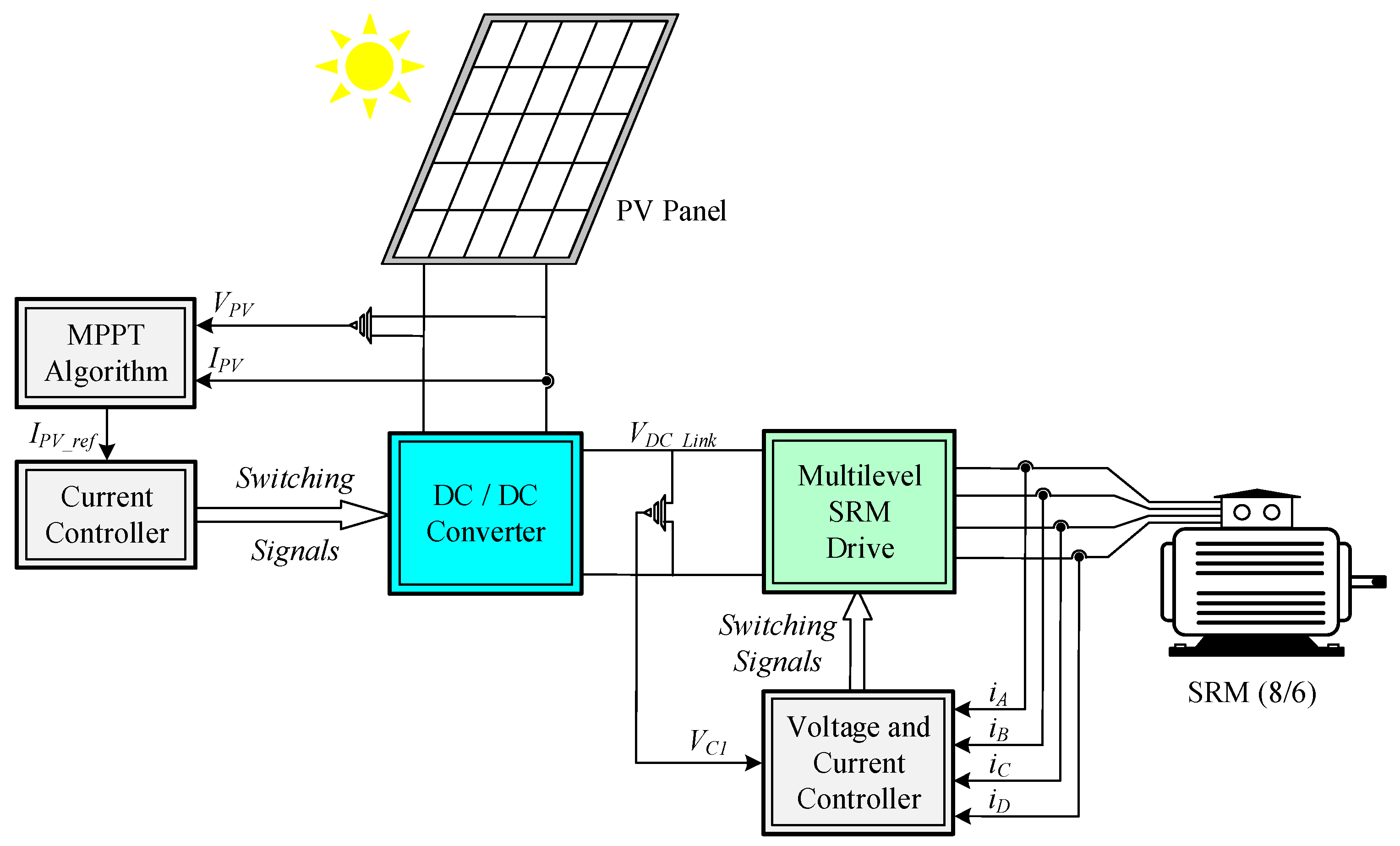
2. Proposed Water Pumping System Supplied by a PV Generator
The proposed water pumping system will be driven by an 8/6
SRM. In addition, it will be fed by a renewable energy source, namely by
PV panels. To obtain the maximum power from the
PV generators, a
DC/
DC converter with dual output is proposed. To obtain the dual output, a converter derived from a combination of the Zeta converter with a
buck–boost converter is used. This combination allows a single switch to be used. Another aspect is that the input current of the converter (output
PV current) will be continuous. The
SRM drive is composed of a multilevel converter that will be supplied by the dual output of the
DC/
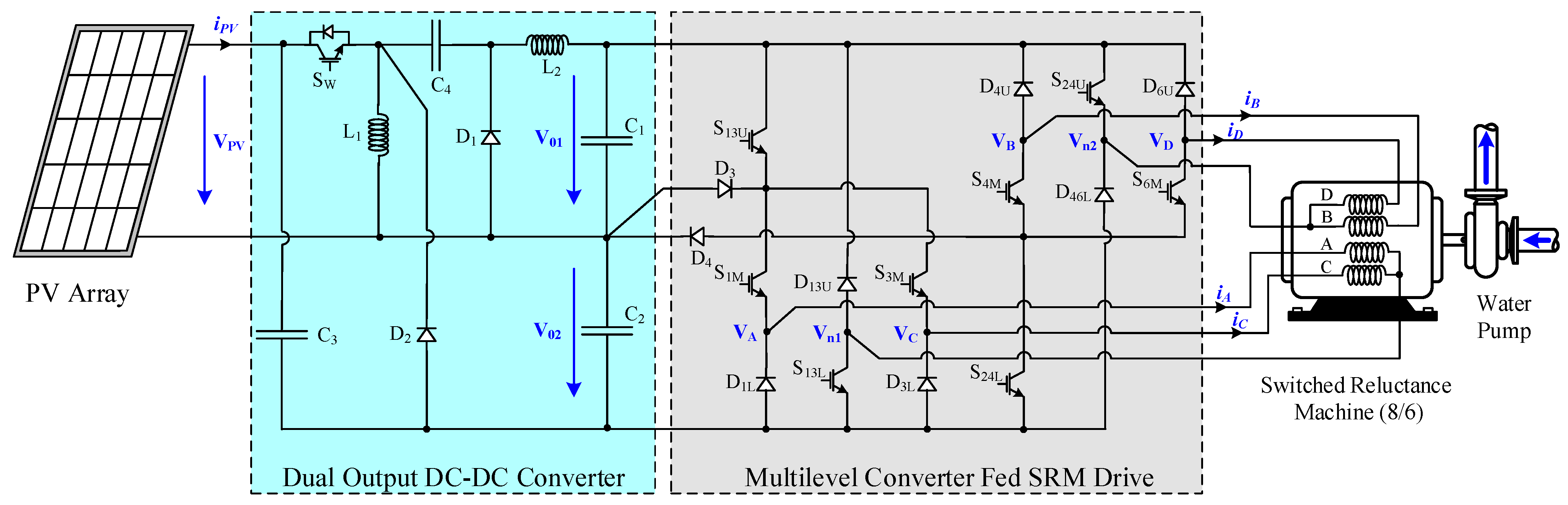
DC converter. The proposed water pumping system is presented in
Figure 1.
As described and presented in
Figure 1, the electronics associated with the pumping system consist of two converters. These converters can be analyzed in a separated way as described in the next section.
In the context of this paper, the water pump is a mechanical device where the shaft is coupled to the SRM using an appropriate transmission. The use of a centrifugal water pump is assumed, since this is one of the most common types of pumps for transferring fluids. The centrifugal pump operates on a concept called forced vortex flow. This means that when a specific quantity of fluid is forced to rotate imposed by an external torque, there is a rise in the rotating liquid’s pressure head, which transfers the fluid from one place to another. The necessary external torque to move the impeller is given by:
where
ρ is the water density in (kg/m
3),
g is the acceleration due to gravity (m/s
2),
HT is the pump’s total head (m),
Q is the water flow rate (m
3),
ω is the speed of the impeller (rad/s) and
η is the efficiency of the pump. The operation limits of this application for water pumping purposes should be determined by the minimum water flow rate required and necessary head (elevation) according to pump characteristic (typical operation curve) such as speed and efficiency.
2.1. Multilevel Converter Fed SRM Drive
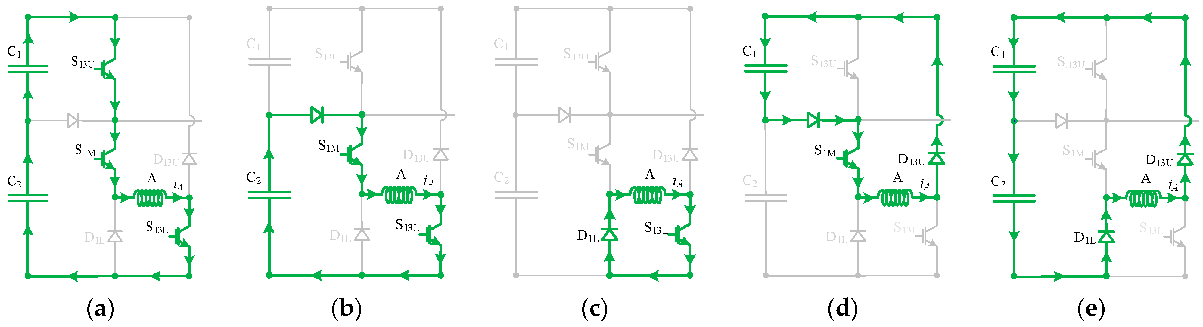
The proposed multilevel converter adopted in the SRM drive was designed with the purpose of minimizing the number of components. In this way, although allowing the application of multilevel voltages to the 8/6 SRM, it only requires eight transistors and eight diodes. Analyzing the possible combinations for the transistor state (ON/OFF) conditions, it is possible to conclude that there are five working modes associated with each motor winding, respectively (example given for motor winding A):
Mode 1: This mode is verified when the devices
S13U,
S1M and
S13L are in the
ON condition. As shown in
Figure 2a, this circuit applies the two input
DC voltages (
VC1 =
Vo1 and
VC2 =
Vo2) to the motor winding. In this mode, the maximum positive voltage applied to the motor winding is (+
VC1 +
VC2).
Mode 2: In this mode, the transistors
S1M and
S13L are in the
ON condition, and the resulting circuit allows the application of the intermediate positive voltage (+
VC2) to the motor winding.
Figure 2b presents the diagram of this circuit.
Mode 3: In this mode, the converter applies the zero-voltage level to the motor winding. This circuit is obtained when only
S13L is in the
ON condition (see
Figure 2c).
Mode 4: In this mode, the circuit allows the application of the intermediate negative voltage level (−
VC1) to the motor winding. This circuit results from the condition in which only the transistor
S1M is in the
ON condition (see
Figure 2d).
Mode 5: This mode is verified when none of the transistors are in the
ON condition. As shown in
Figure 2e, the circuit applies the maximum reverse voltages of the two input
DC sources (
VC1 and
VC2) to the motor winding. Therefore, the maximum negative voltage applied to the winding is (–
VC1 −
VC2).
These operating modes can also be presented mathematically. Thus, for the development of the mathematical model, the power semiconductors are considered as ideal switches. In this way, associated with the transistors, Boolean variables are considered, as described by (2):
where
k = 1, 3, 4, 6,
j = 13, 24 and
I =
U,
M.
Using these variables, taking into consideration the possible combinations for the transistors’
ON/OFF conditions and in accordance with the Kirchhoff laws, it is possible to obtain the mathematical expressions of the voltages applied to the motor windings, as function of the switches. These expressions are then given by:
where
β is binary variable that is a function of:
where
w = A, B, C, D.
According to the previous expressions, it is possible to confirm the multilevel voltage operation of the converter, namely by verifying that five different voltage levels can be applied.
2.2. Operation in Continuous Conduction Mode
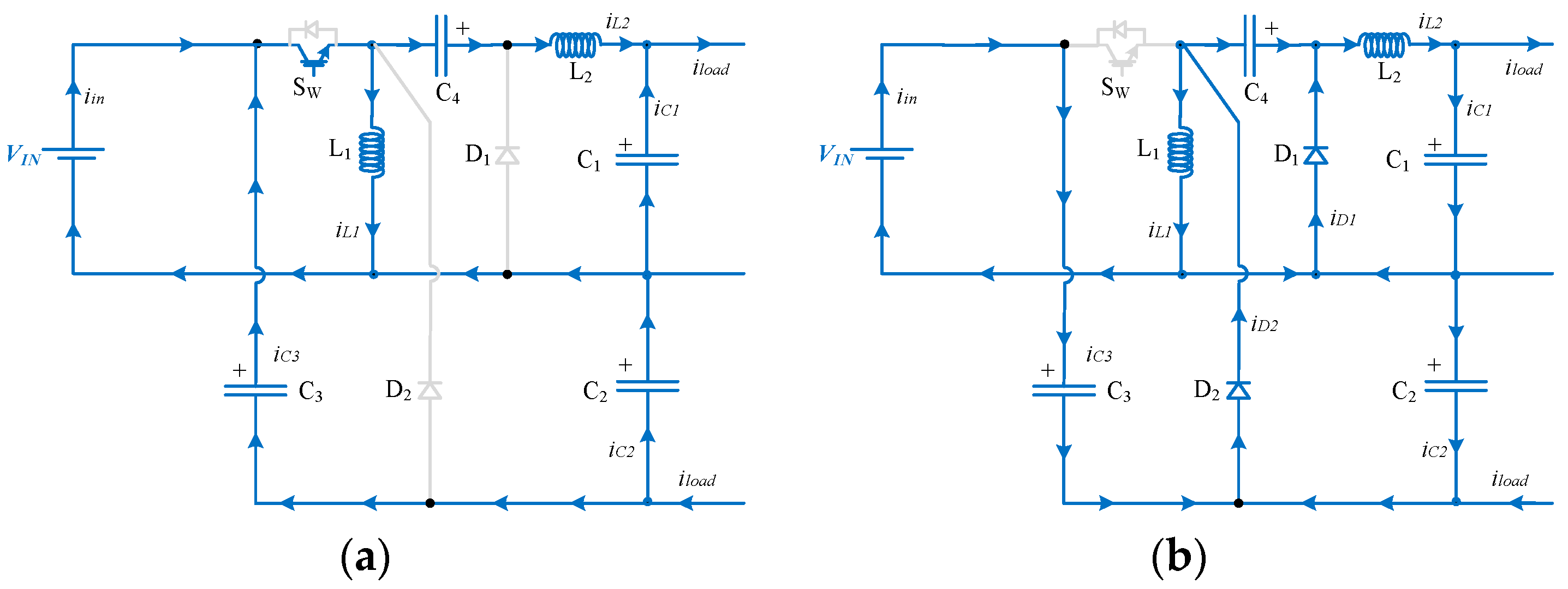
Similar to the SRM drive that operates the motor, the DC/DC converter was also designed with a reduced component count. In this way, although the converter has the specification of having two outputs, it only requires one switch. Thus, considering that the converter operates in continuous conduction mode (CCM), it is possible to conclude that there are only two working modes, respectively:
Mode 1: This mode is verified when the converter switch
Sw is in the
ON state and diodes
D1 and
D2 are in the
OFF state, resulting in the circuit configuration of
Figure 3a. In this mode, both inductors (
L1 and
L2) are in charging mode, through which their currents will increase. Inductor
L1 will be charged by the input power source. On the other hand, the capacitors
C3 and
C4 will discharge their storage energy to the inductor
L2 and to the load. In this mode, capacitors
C1 and
C2 will also discharge to the load. The equations for the inductors’ voltages and capacitors’ currents in this mode are as follows, where
iload is the nominal current of the
SRM:
Mode 2: In this mode, the converter switch
Sw changes to the
OFF state. In an opposite way, diodes
D1 and
D2 change to the
ON state, resulting in the circuit presented in
Figure 3b. In contrast to mode 1, in this mode, both inductors (
L1 and
L2) will be in discharging mode. In this way, their current will decrease. The capacitors
C3 and
C4 will be in charging mode, through which inductor
L1 will discharge to such capacitors. Inductor
L2 will discharge to capacitors
C1 and
C2. The equations for the inductors’ voltages and capacitors’ currents in this mode are as follows:
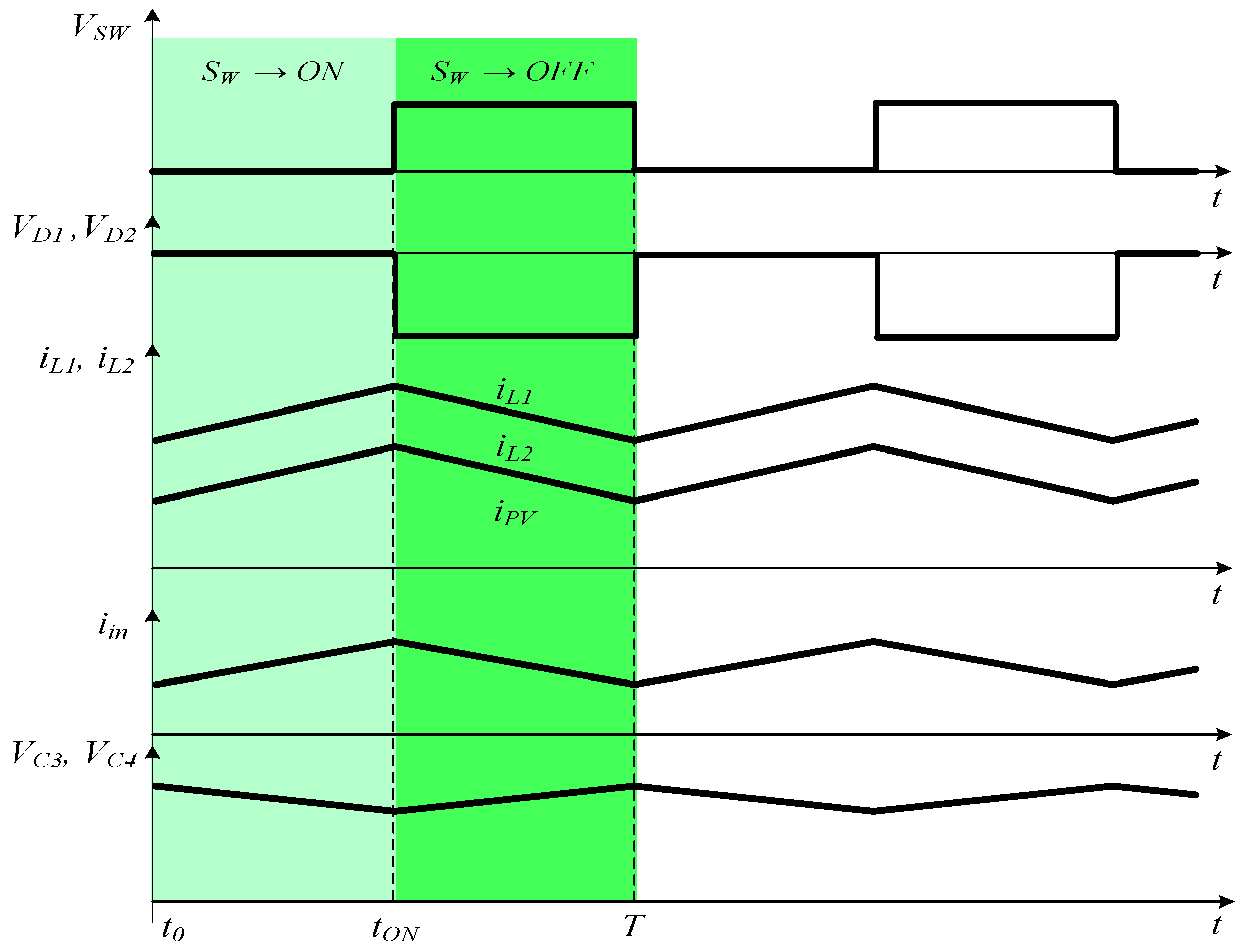
One aspect that is possible to verify from these modes is that the
PV current (input of the converter) will be continuous. The converter waveforms associated with the two operating modes are presented in
Figure 4.
Taking into consideration both operating modes and the zero average voltage in both inductors over one cycle, the static voltage gain of this
DC/
DC converter can be obtained. The average voltages in the inductors are given by:
Taking into account the expressions given by (5) and (6), the converter static voltage gain of each output and capacitor voltages can be obtained, which are given by:
From the expressions given in (8), it is possible to see that the static voltage gains of both outputs are equal and have a buck–boost characteristic.
2.3. DC/DC Component Design
This section presents the design of the components of the
DC/DC buck–boost converter. During mode 1, the capacitor
C4 discharges according to the
iL2 current (see
Figure 3a) given by Equation (9).
Therefore, is possible to design the capacitor for a permissible voltage ripple. The previous equation can also be expressed as (10), where
δ is the duty cycle and
fsw the switching frequency.
Considering that the average current over the output capacitor
C1 in each cycle is zero, the capacitor
C4 value depends on the load current, resulting in Equation (11).
Inserting the duty cycle and considering Equation (8), this leads to Equation (12).
From the charge variation of
C3, it is possible to conclude that the voltage across
C3 decreases during mode 1, which leads to:
Similarly, one can also design the capacitor
C3 for a permissible voltage ripple as happens with capacitor
C4, Equation (14).
Considering that the average current over the output capacitor C
3 in each cycle is zero, the capacitor C
3 value depends on the load current, resulting in Equation (15):
Inserting the duty cycle and considering Equation (8), this now leads to Equation (16).
In general, the differential Equation (17) represents the current evolution on a capacitor C
2.
After linearization, Equation (17) becomes Equation (18).
During mode 1, the instantaneous current in the capacitor C
2 is equal to the output current. Additionally, in mode 1, we have Δ
t =
δTsw =
δ/
fsw, thus:
Observing
Figure 4, it is possible to verify that when the power semiconductor is turned on, the charge variation
ΔQ over the capacitor C
1 is equivalent to the area of a triangle with
height and time base 0.5
Tsw, thus:
Similar calculations can be performed to obtain the values of both inductors. During mode 1, the input voltage lies across
L1 and the current through it increases by Δ
IL1. The inductor
L1 can be obtained for a chosen current ripple according to Equation (21).
Replacing the duty cycle given in (8), it is possible to obtain Equation (22).
During mode 1, the voltage across
L2 is given by Equation (5), and the current through it increases by Δ
IL2. The inductor
L2 can be obtained for a chosen current ripple according to (23).
Replacing the duty cycle and other relations given in Equation (8), it is possible to obtain (24).
The maximum reverse voltage of the converter switch
Sw and maximum continuous current are given by Equations (25) and (26).
When the converter switch
Sw is turned on, diodes
D1 and
D2 are turned off. In this situation, the maximum reverse voltage and maximum continuous current over
D1 (during the
ON state) are given by (27) and (28), respectively.
Similarly, for the diode
D2, we have Equations (29) and (30).
To analyze the design of these components, an example of the determination of their values is now presented. The following calculations are based on Equations (8)–(30) to estimate the component values. A
DC voltage of 40 V and a
DC output voltage of 200 V are assumed, which results in a duty cycle of:
Considering a switching frequency
fsw = 10 kHz and assuming a maximum variation of 0.5 A in
L1 (Δ
IL1), it is possible to calculate the value of inductor
L1 based on Equation (21):
Considering the duty cycle of Equation (30), the input voltage
Vi = 40 V and the voltages of capacitors
C1 and
C4 given by Equation (8), and assuming a maximum variation of 0.5 A in
L2 (
ΔIL2), it is possible to calculate the value of inductor
L2 based on Equation (23):
Assuming an output power of 1500 W and considering that
C3 and
C4 achieve a voltage variation of 2%, is possible to calculate the values of these capacitors according Equations (12) and (16):
In the same conditions, assuming that the output capacitors
C1 and
C2 achieve a voltage variation of 1%, is possible to calculate the values of these capacitors according Equations (19) and (20):
3. Control of the Proposed System
Another aspect that must be taken into consideration is the control of the proposed pumping system. There are several aspects that should be considered, such as the extraction of the energy from the
PV panels and the control of the motor. The control of the extracted energy from the
PV panels will be ensured by the
DC/
DC converter. Thus, since the purpose is to extract the maximum energy, an
MPPT algorithm will be considered. This algorithm will establish the control of the
DC/
DC converter switch. In order to maintain the balance between the generated energy from the
PV panels and the motor consumption, there is a voltage controller associated with the motor drive. In this way, this voltage controller will ensure that the
DC/
DC converter output voltages will be stable at a specific reference value. A block diagram of the control system for the proposed solution is presented in
Figure 5.
Regarding the
MPPT algorithm that will ensure the harnessing of the maximum energy that the solar panels can supply, different approaches have been proposed. Among them, the algorithms that are most used are the incremental conductance and perturb and observe [
51]. Other algorithms including the use of metaheuristic optimization techniques were proposed. Examples of these can be seen in works [
52,
53]. Although these algorithms usually allow excellent results to be obtained, their implementation usually requires some complexity. Thus, for this system, an approach considering its simplicity and possibility of being implemented with a simple analogue electric circuit will be used. This algorithm is based on the time derivative of power, as well as voltage. In this way, singularities are avoided that can be found with an algorithm based on the derivative of the power and voltage or current [
56]. This algorithm will then be developed taking into consideration the typical
I–V curve of the
PV panels. In accordance with this, the
MPP is achieved when the derivative of the voltage and power are zero. However, the movement to that point can be achieved through the derivative of the power and voltage in order of time. Therefore, if the system is within the left side of the
MPP and if the condition
dP/
dt > 0 and
dV/
dt > 0 is ensured, this will result in a trajectory in the direction of the
MPP. On the other hand, if the system is within the right side of the
MPP and if the condition
dP/
dt > 0 and
dV/
dt < 0 is ensured, this will also result in a trajectory in the direction of the
MPP. Thus, the conditions to ensure that the system will move to the
MPP are given by (37).
Starting from the conditions given by (37), the
MPPT function regarding the derivative of voltage and power in order of time can be developed. Therefore, taking into consideration that the input current of the
DC/
DC converter is regulated by a hysteretic current controller, the reference current is given by the following control law:
However, it is possible to simplify the previous control law even more. To do so, instead of using the derivative of the power and voltage in order of time, their signal will simply be considered. In this way, the
MPPT only consists of a single expression given by Equation (39), which can easily be implemented through an analogue electronic circuit.
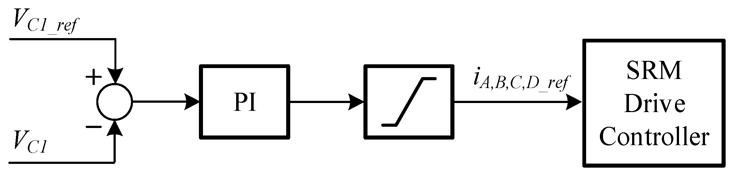
One important aspect that must also be considered is the balance between the generated power and the power consumption of the motor. This will be ensured by the adopted voltage controller of the
SRM drive. Therefore, this voltage controller must ensure that the output voltage of the proposed
DC/
DC converter remains in steady state in the reference value. To ensure this, the voltage controller will define the current references for the
SRM drive controller. A
PI compensator will be used for this voltage controller, as shown in
Figure 6. Regarding the
PI parameters, they have been determined through trial and error obtained from several repeated experiments.
4. Simulation Results
With the purpose of confirming the expected performance of the proposed solution, the system was initially implemented in a simulation software. The adopted program was one of the most used in these kinds of systems, namely the
Matlab/Simulink. For the power electronic converters, inductors (
L1 and
L2) of 5 mH and 10 mH, respectively, and capacitors of 22 μF (
C1), 680 μF (
C2) and 220 μF (
C3 and
C4) were used. It should be mentioned that these values are based on the previous determination of these components. However, they are not completely equal, since for the experimental tests, components that exist in the laboratory were used, and the same values that were used in that part were used for comparison purposes. Regarding the machine, an 8/6
SRM was used. Regarding the
PV panels used in this system, their characteristics can be seen in
Table 1. The component values of the power electronic converters were obtained from the equations presented in
Section 2.3, and input
DC voltage 40 V,
DC output voltage 200 V, 1500 W output power,
fsw = 10 kHz, a ripple limit in capacitor voltages Δ
VC1 = Δ
VC2 ≤ 1%, Δ
VC3 = ΔVC4 ≤ 2%, and inductor current ripples Δ
IL1 = Δ
IL1 < 10% were used, which are values that are usually used by designers. However, the adopted values are higher since they have been chosen because of the existing components in our laboratory.
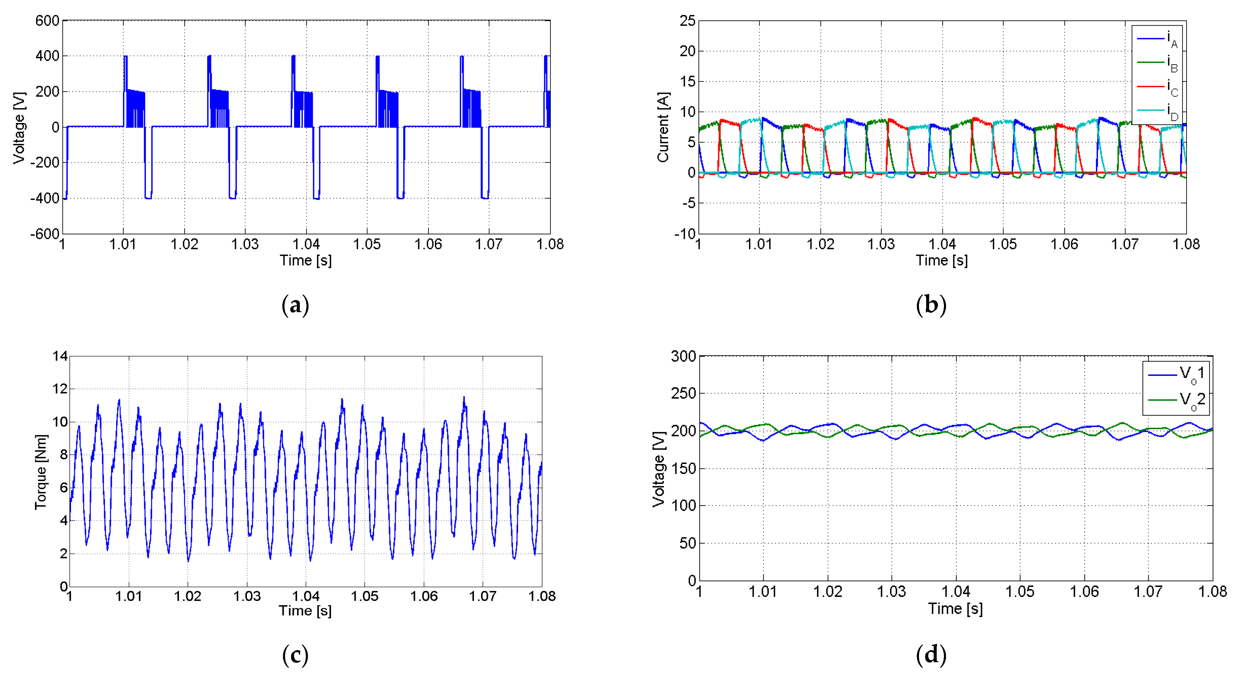
Several simulation tests are presented in this section. The first test was conducted with 700 W/m
2 (irradiance) and 25 °C (ambient temperature). The obtained waveforms of this test are presented in
Figure 7. The waveforms of this figure are related to the voltage applied to winding A, with currents in all windings and input
DC voltages applied to the drive (or
DC/
DC output voltages). From the analysis of the voltage applied the motor winding
A (
Figure 7a), the multilevel operation of the drive is noticeable, where the two positive voltage levels are clearly visible. Moreover, it is possible to see that, initially, when the winding is magnetized and at the end when it is demagnetized, the maximum voltage levels are applied. One of the voltage levels that does not appear in this waveform is the −
VC1 (
Figure 2d). The reason for this is because when the demagnetization is necessary, it should be carried out as fast as possible. In this way, the negative voltage that is applied is −
VC1 −
VC2 (
Figure 2e). Since there are no negative currents in this motor, there is no need to apply the negative voltage level
−VC1 (
Figure 2d) to maintain a specific negative current level. On the other hand, the currents in the motor windings are clearly controlled, as visible from the waveforms presented in
Figure 7b. Another aspect that can be seen is the effect of the switching action of the inverter devices on the
SRM pulsation torque. As can be seen from
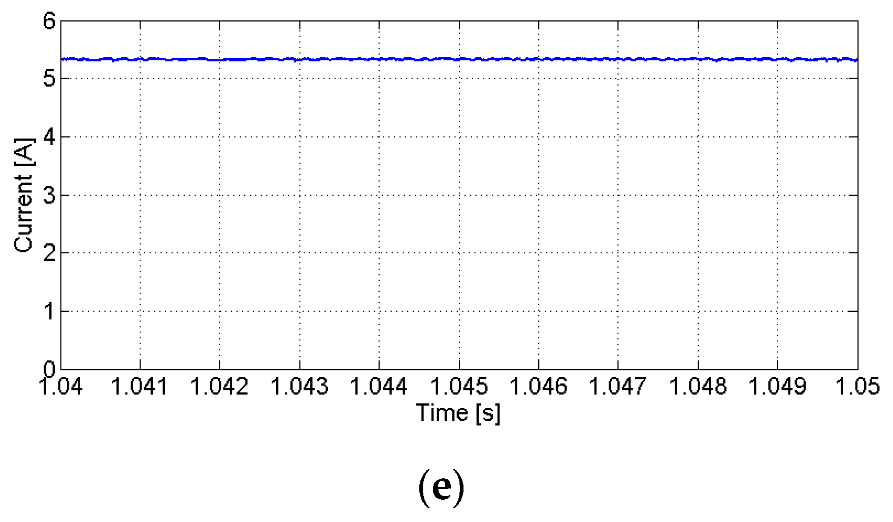
Figure 7c, there are two different impacts. The first one is related to the high-frequency switching of the inverter devices originating from the hysteretic comparator. Since this hysteresis is low, the current ripple is also low, so the impact on the torque is also low. On the other hand, this high-frequency switching will affect the voltage applied to the motor windings but has a lower impact on the current. Due to this high frequency, the motor winding will behave as a low-pass filter. As a result, this will also attenuate the impact on the torque. However, the major problem appears during the transitions between the phase current, from which a pulsation torque will originate. This last problem can be attenuated using advanced control techniques. However, for this specific application, this is not significant. Finally, analyzing the waveforms of the input
DC voltages applied to the drive (output voltages of the
DC/
DC converter) presented in
Figure 7d, it is possible to see that they are balanced and stable at the reference value (set to 200 V). On the other hand, as shown in
Figure 7e, the converter input current is continuous, which is one advantage considering the characteristics of the
PV panels.
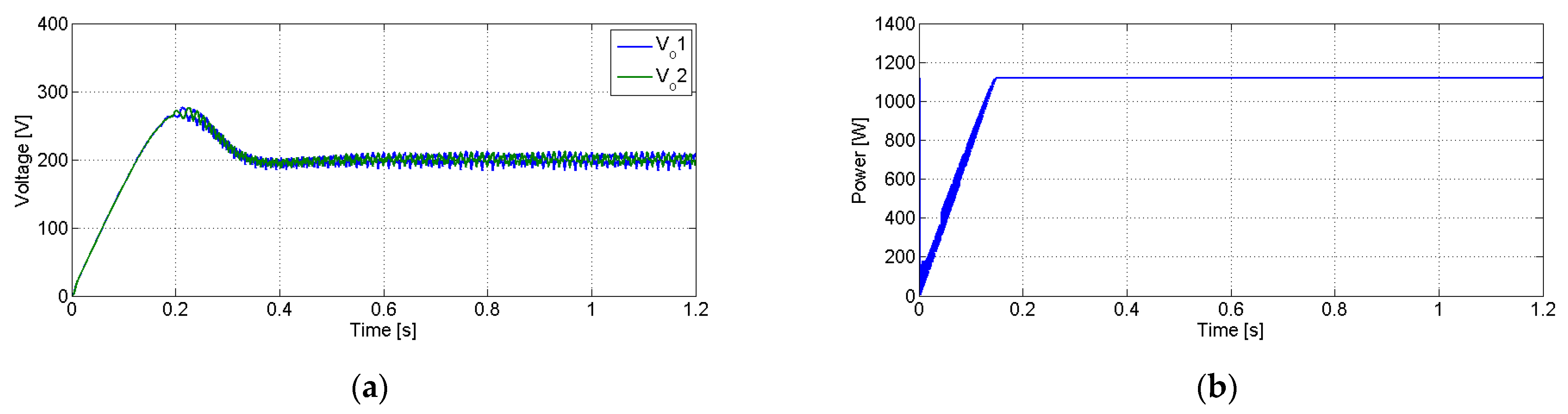
Simulation tests in transient conditions were also carried out. In this condition, the system was suddenly connected considering the same values of the previous test, which can be seen in
Figure 8 (notice that the voltages and currents of the capacitors and inductors are initially zero). Analyzing the output
DC/
DC converter voltage waveforms presented in
Figure 8a, it is possible to see they started at 0 V and stabilized at 200 V (reference value) in a balanced state. It should be mentioned that until the output voltages reach the reference value, the pumping system is not operating. In this way, these results confirm the predicted operation of the voltage controller. Regarding the generated power from the
PV panels, it is possible to see from
Figure 8b that, starting from zero, it will increase immediately until it reaches the
MPP. On the other hand, it is also possible to confirm that after reaching the
MPP, it will stay at that point. In this way, the predicted capability of the proposed
MPPT algorithm is confirmed.
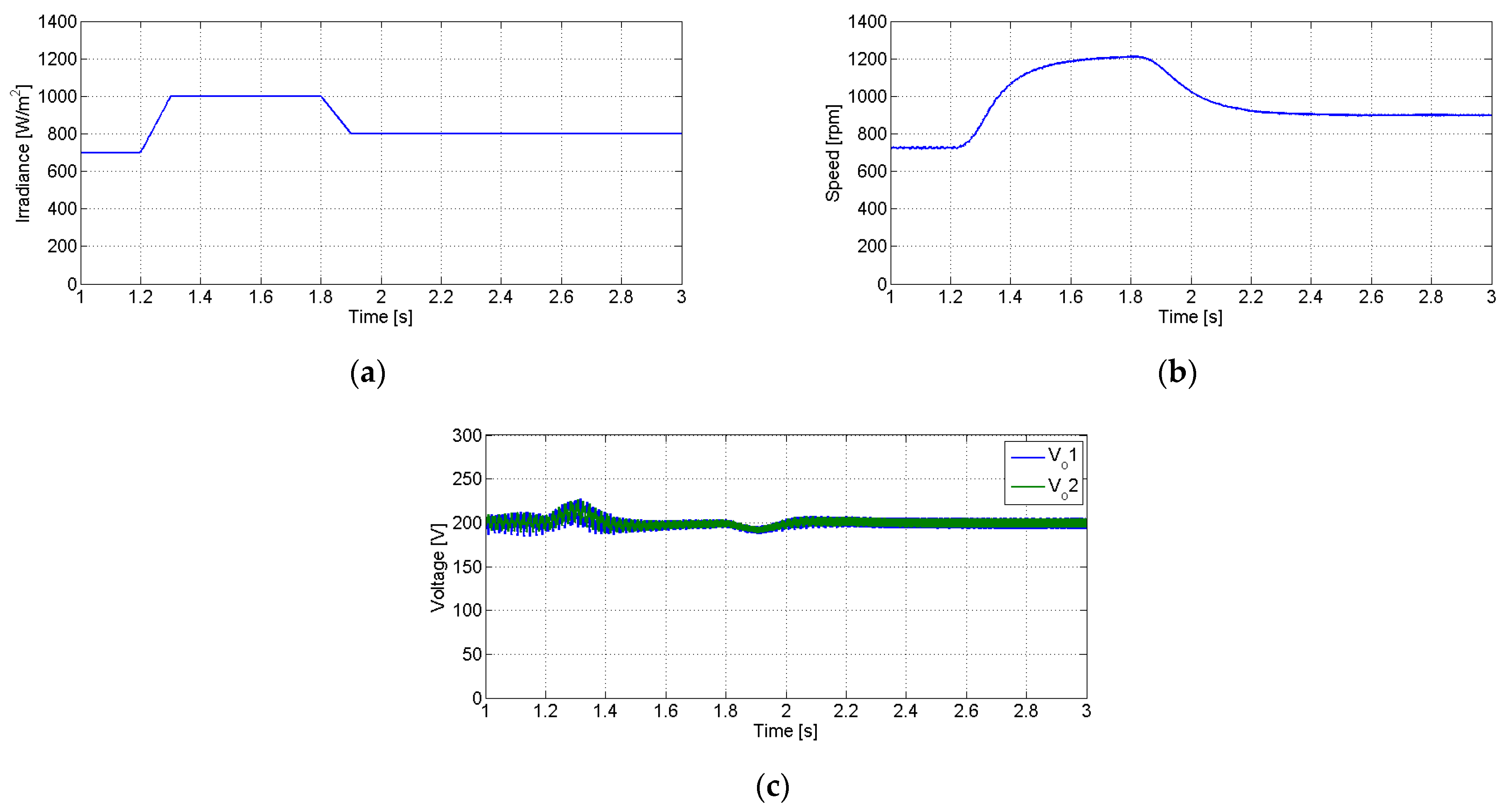
Another transient test that was considered was the solar irradiance variation. Thus, initially a solar irradiation of 700 W/m
2 was considered, increasing to 1000 W/m
2 at 1.2 s and returning again to 800 W/m
2 at 1.8 s. This irradiation profile is shown in
Figure 9a. The waveform of the
SRM motor speed is shown in
Figure 9b. As expected, with the increment in the
PV generated power (due to the increase in the irradiance), there is also an increment in the motor speed, and vice versa. The behavior of the voltage controller is also presented through the
DC/
DC output voltages shown in
Figure 9c. Indeed, this figure shows that these voltages remain in the reference value, confirming that the balance between the generated power and the power consumption of the motor is ensured.
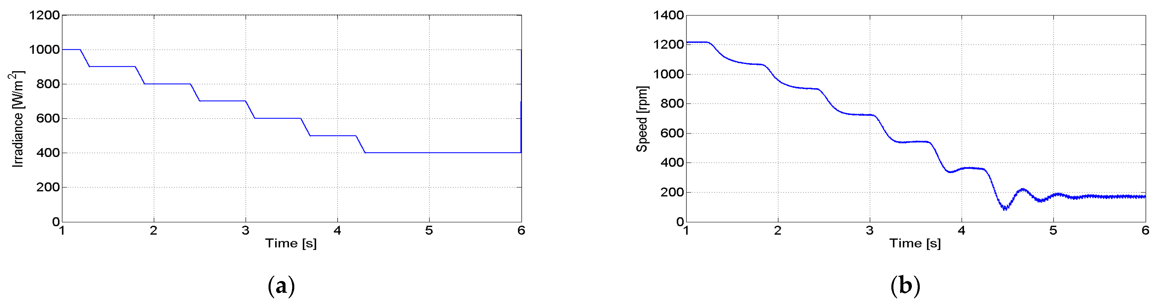
Tests with respect to various irradiances applied to the
PV panel were also carried out. Thus, in order to see the impact of these changes in the system, in
Figure 10, the obtained waveforms when the irradiance changes from 1000 W/m
2 to 400 W/m
2 in steps of 200 W/m
2 are presented. In
Figure 10a, the irradiance applied to the
PV panel is presented, and
Figure 10b shows the motor speed. As expected, the motor speed changes with the irradiance once the generated power also changes. In fact, the motor speed changes from 1220 rpm to 170 rpm in steps just like the irradiance. It should be stated that in pumping systems, this change in speed is generally not very important, although it must be above a specific minimum value.
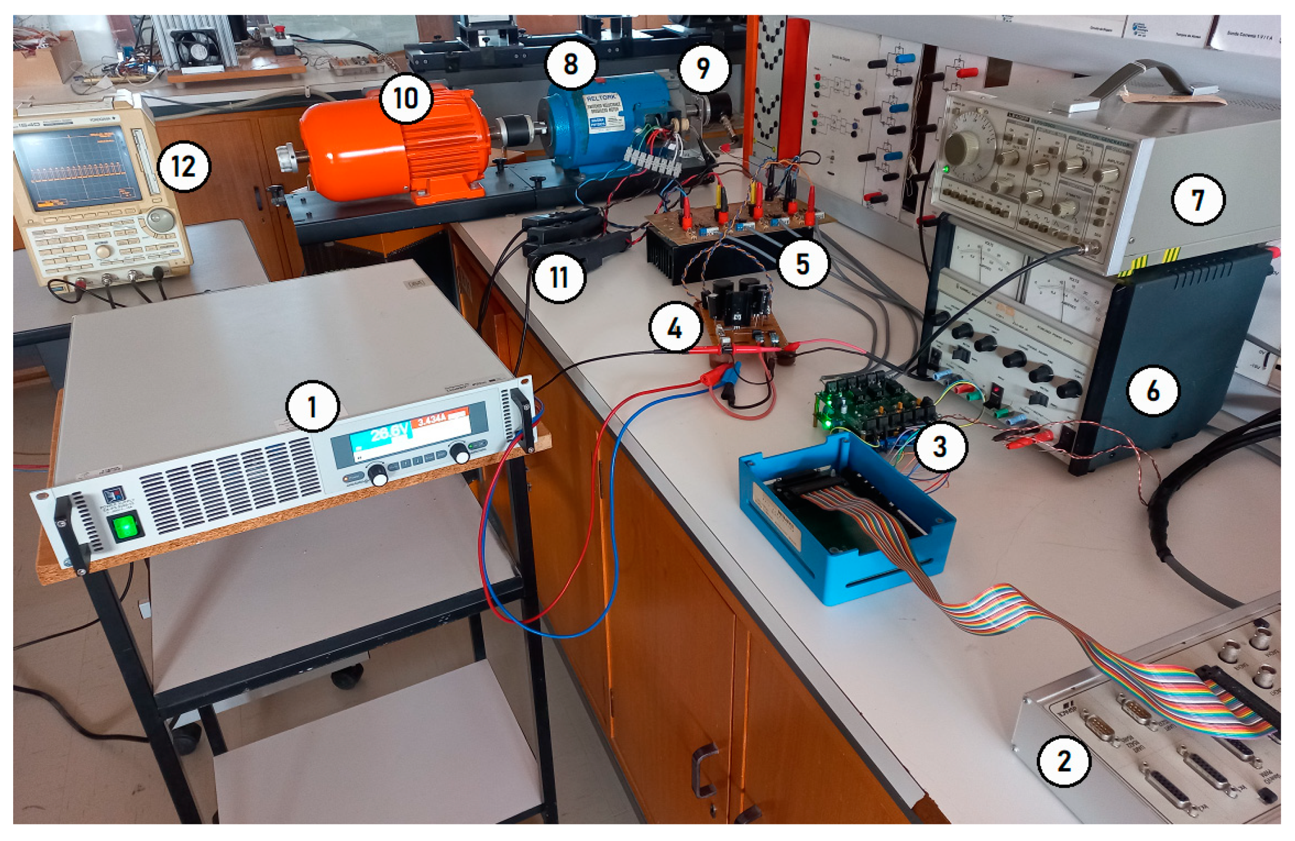
5. Experimental Results
The proposed solution was also tested using a laboratory prototype combining the power electronic converters and the
SRM. The parameters of the components used for this prototype were the same as the ones used for the simulation tests. The
PV panels were simulated using a controlled voltage source (EA PS8360-30 2U) in which their characteristics were programmed to obtain the typical I–V curves. An 8/6
SRM machine was also used.
Figure 11 shows the experimental test bench with the proposed laboratorial prototype. In figure, it is possible to see: 1—the controlled voltage source (EA PS8360-30 2U); 2—the digital signal processor (DSPACE 1104) used to control the multilevel
SRM drive and
MPPT algorithm; 3—the gate drive circuits; 4—the
DC/
DC converter; 5—the multilevel
SRM drive; 6—the auxiliary power source for the gate drive circuits; 7—the signal generator; 8—the 8/6
SRM machine; 9—the absolute encoder for measuring speed and rotor position; 10—the
DC machine used to simulate the water pump; 11—the current probes and 12—the DL1540 Yokogawa oscilloscope.
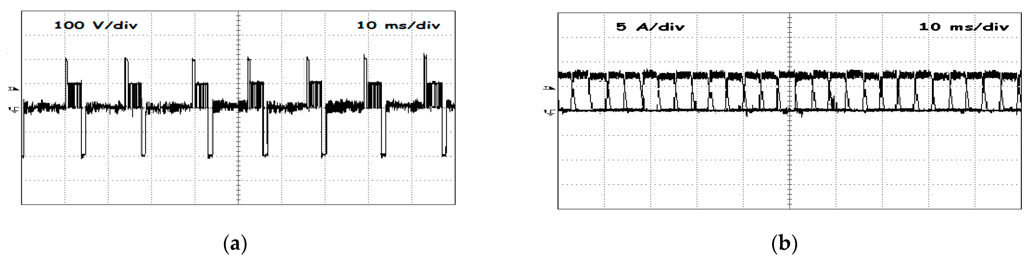
The laboratory results of the first test presented in
Figure 12 were obtained in steady state considering a 700 W/m
2 irradiance and a 25 °C ambient temperature. The results shown in this figure are the voltage applied to motor winding
A (
Figure 12a) and currents in all the phases of the
SRM (
Figure 12b), as well as the output voltage (
Figure 12c) and input current (
Figure 12d) (applied to the
SRM drive) of the
DC/
DC converter. From these waveforms, it is possible to conclude that they are similar to the ones obtained in the simulation tests. They also confirm the multilevel voltage characteristics of the
SRM drive and continuous input current of the
DC/
DC converter.
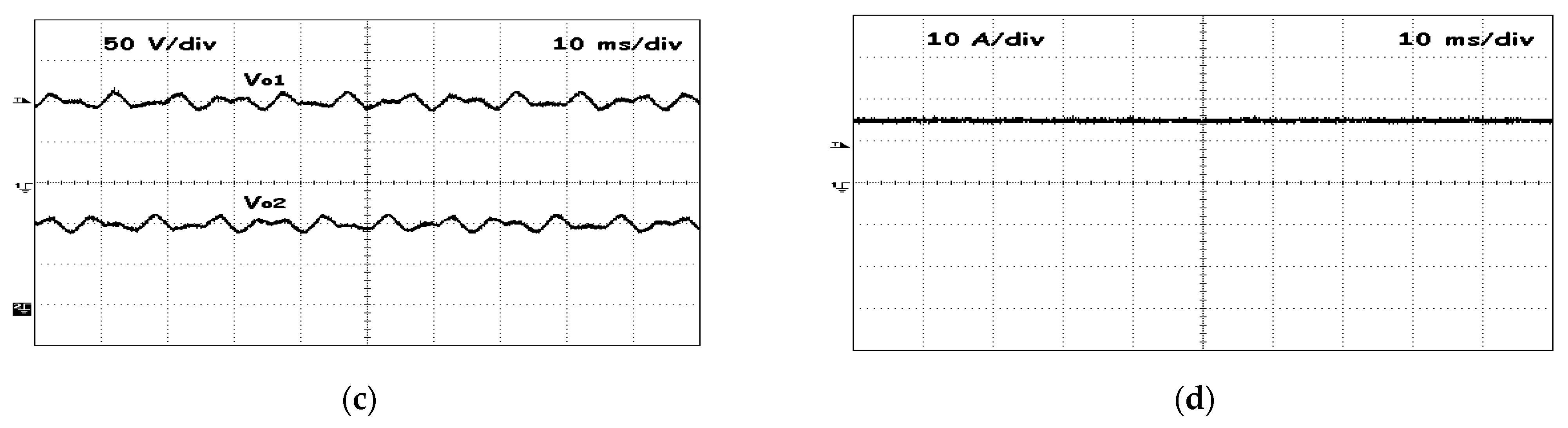
Similar to the simulation tests, experimental transient tests were also performed. The first one was carried out considering the initial connection of the system. As shown in
Figure 13, it is possible to conclude that the output voltage of the
DC/
DC converter starts at 0 V, but will rapidly achieve the desired (reference) value of 200 V. The balance of the
DC/
DC output capacitors voltages is also verified. It should be mentioned that, like in the simulation tests, the pumping system was only operated after the
DC/
DC output voltages reached the reference value.
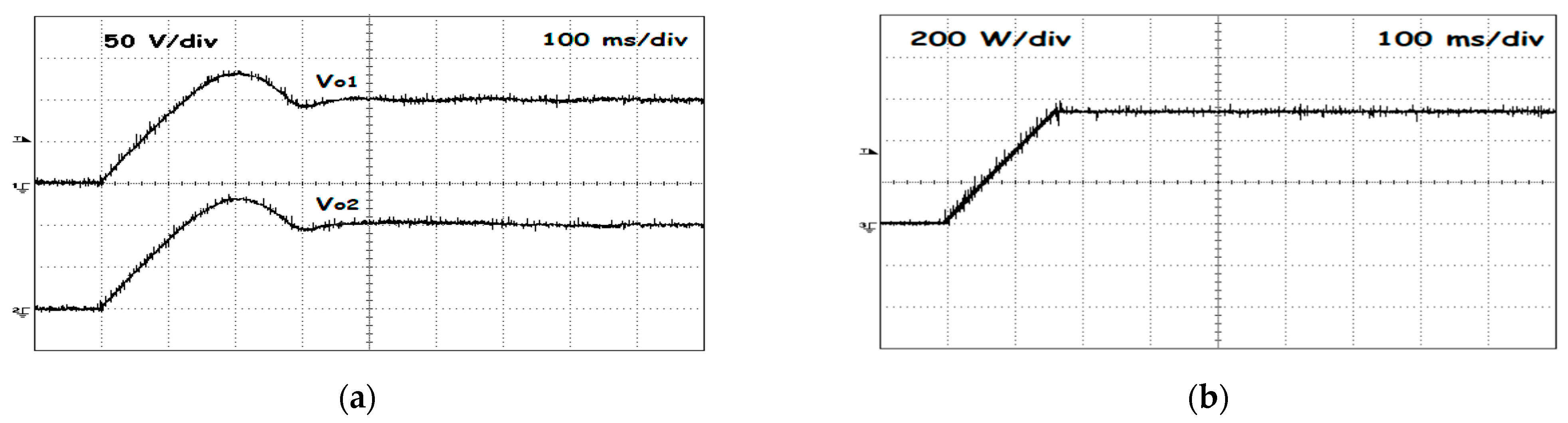
A laboratory test in which the solar irradiance was not always constant was also performed. Thus, for this test, a first change in the solar irradiance from 700 W/m
2 to 1000 W/m
2 was implemented, then this irradiance was maintained and finally another change to 800 W/m
2 was implemented. The implemented solar irradiance, speed of the
SRM and output voltages of the
DC/
DC converter results are presented in
Figure 14. This figure confirms that the motor speed follows the irradiance and that the
DC/
DC output voltages are maintained at the reference value. These results also confirm the ones obtained in the simulation tests.


 ,
, 


