
New Simulation Tool for Architectural Design in the Realm of Solar Radiative Transfer

 , , , and
Abstract
:
1. Introduction
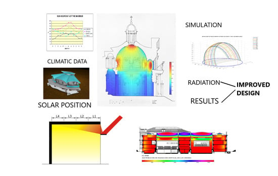
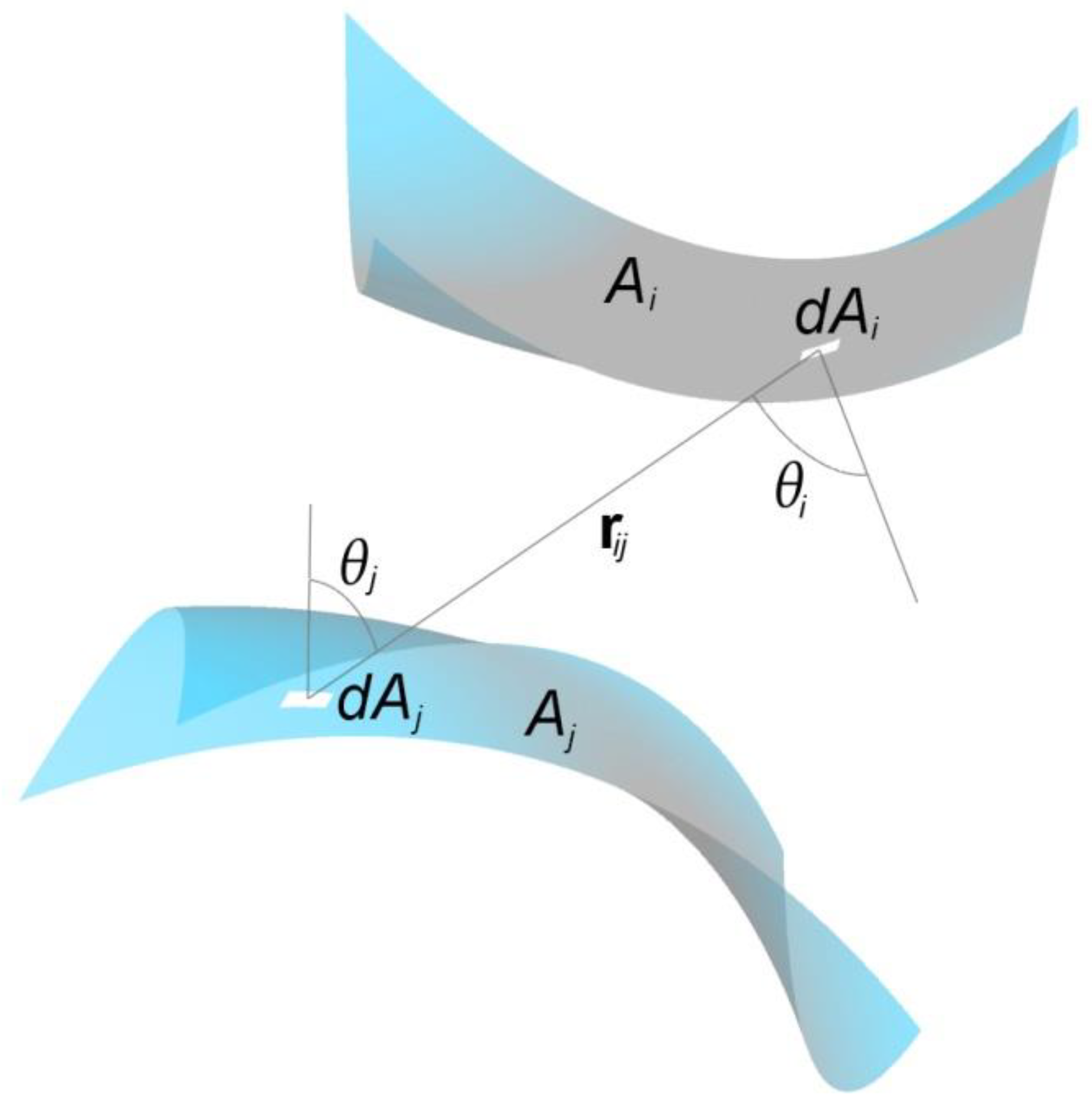
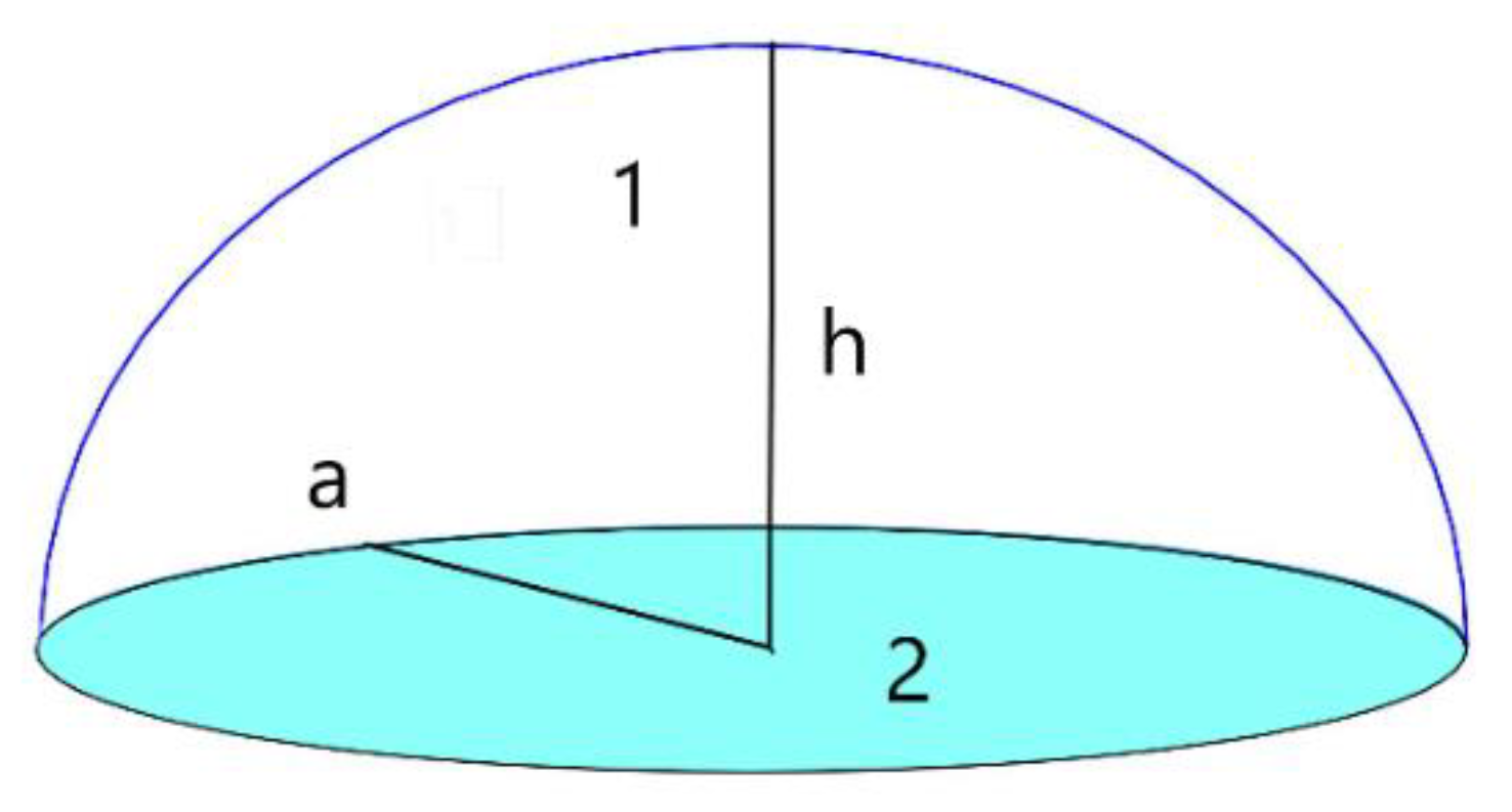
2. Methodology
3. Results of Utilizing the Simulation Tools
3.1. Simulations of Radiative Transfer in Buildings of the Past
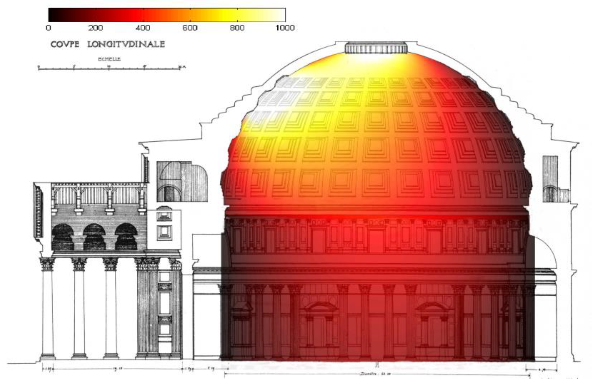
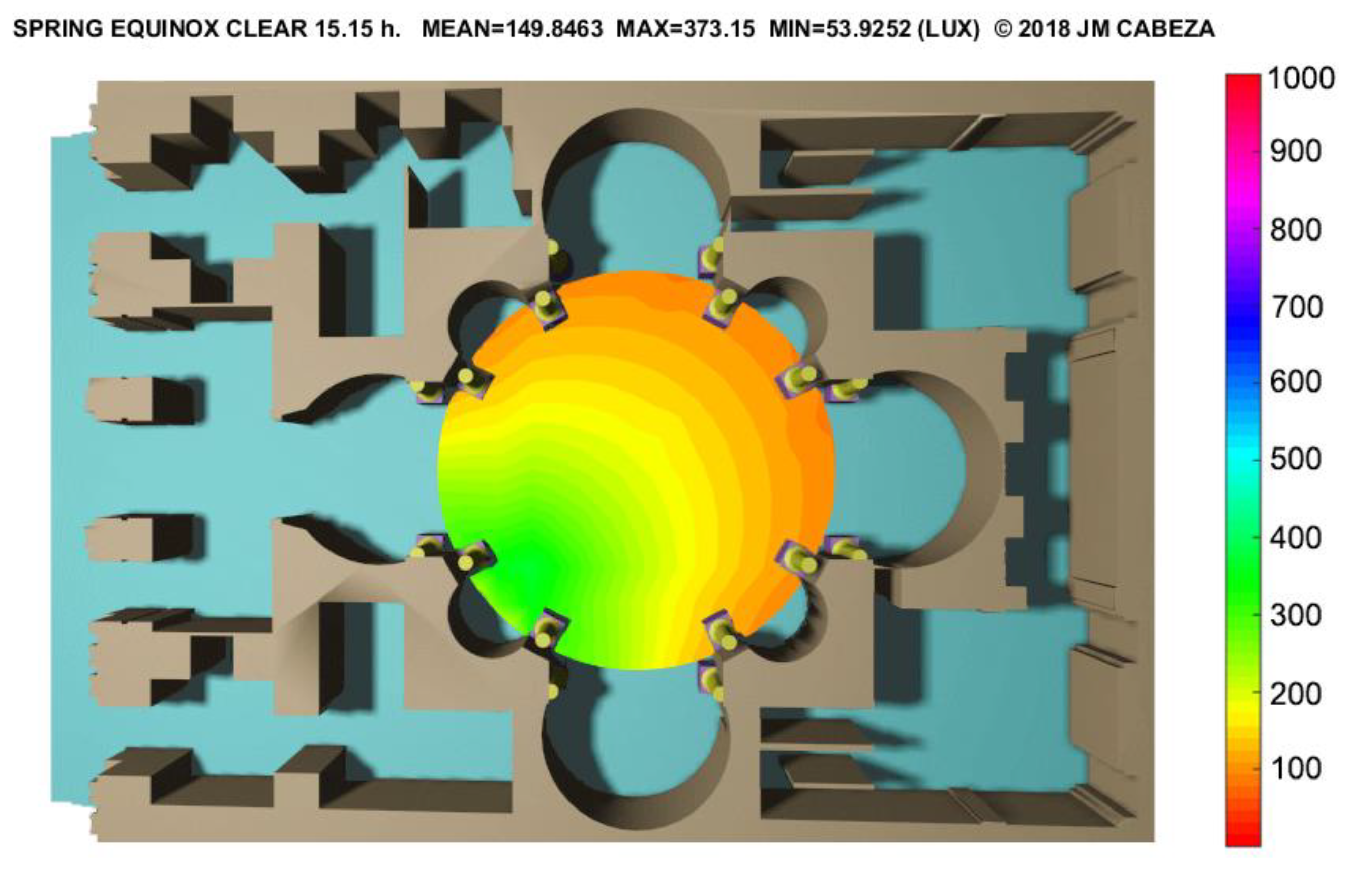
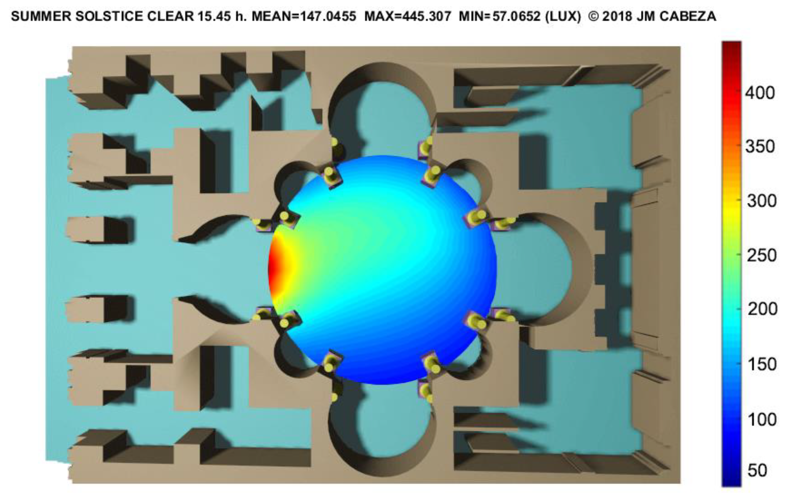
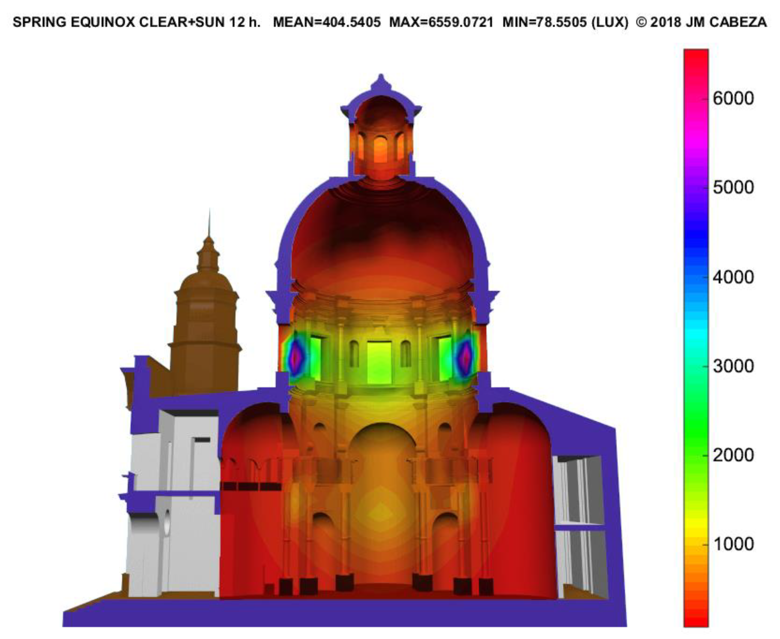
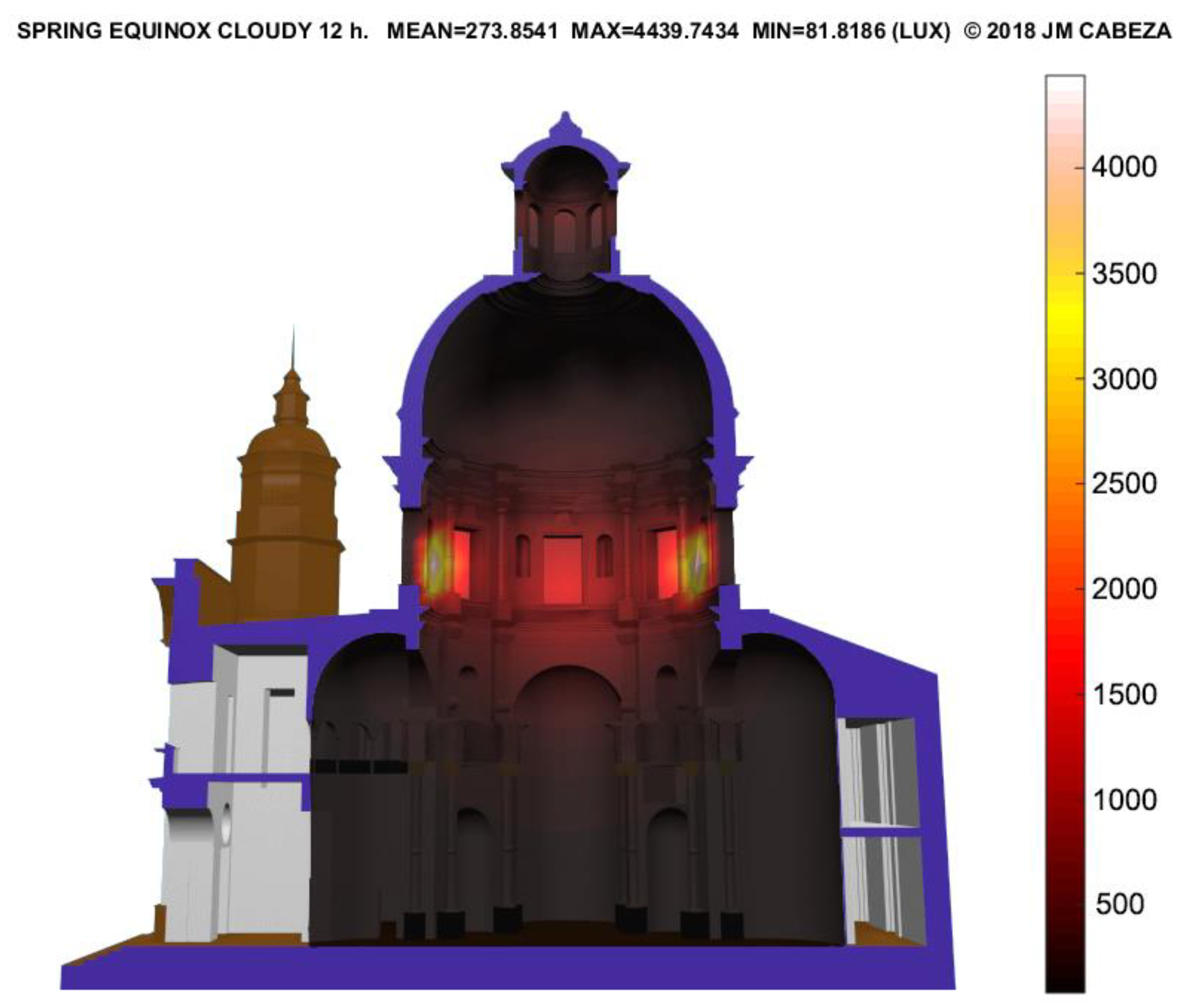
3.1.1. The Roman Pantheon
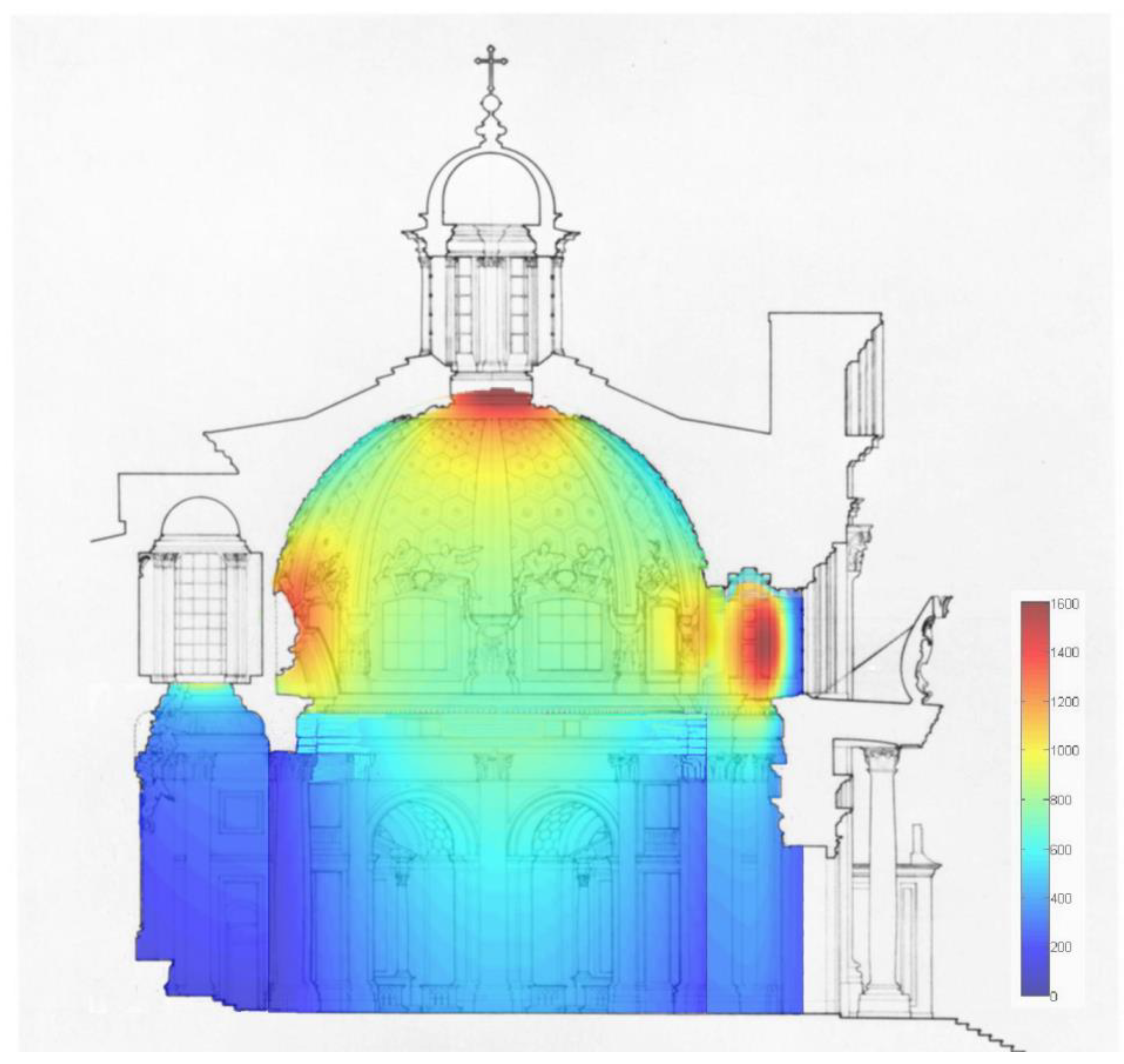
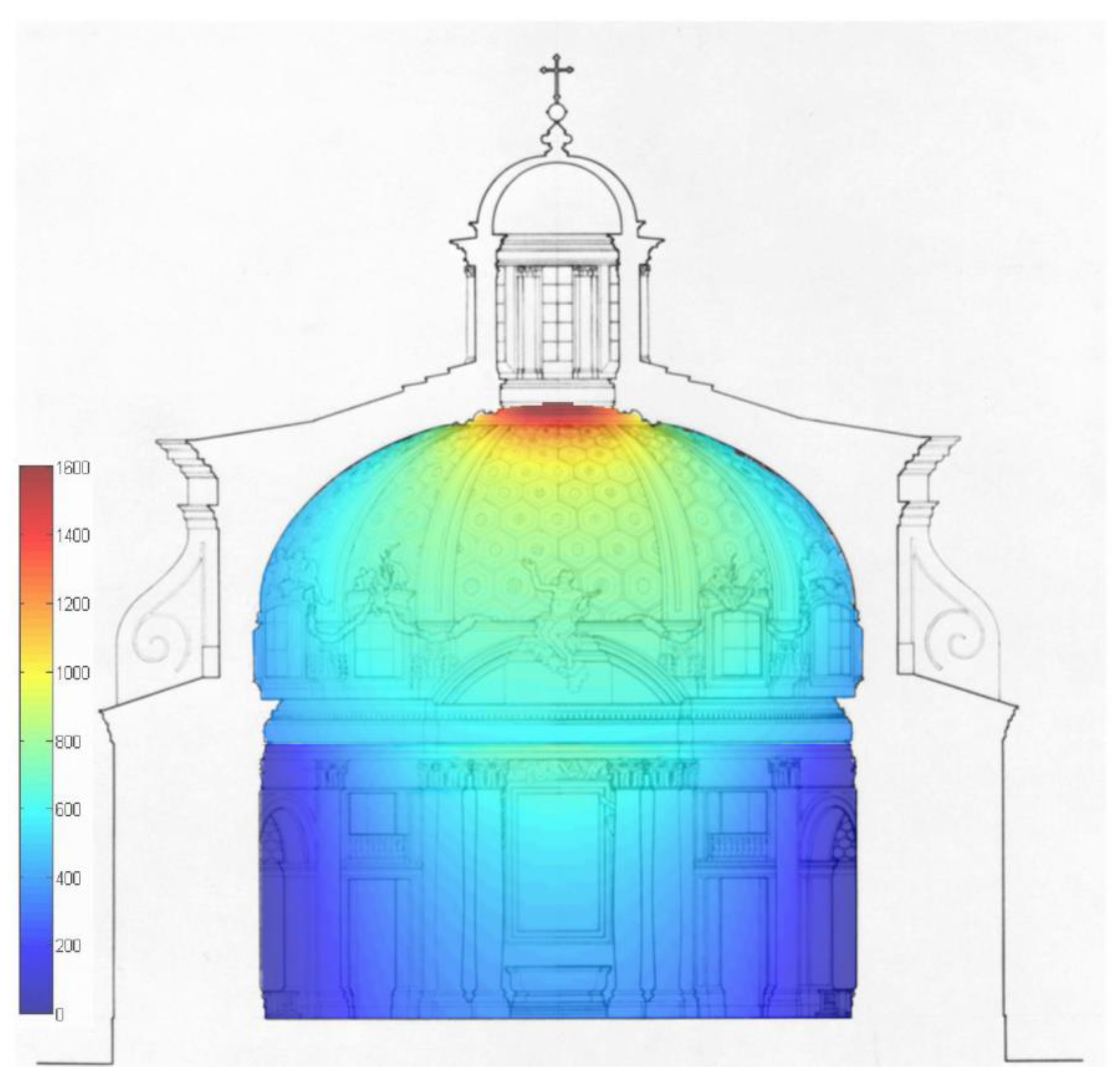
3.1.2. The Church of St. Louis of France (Seville)
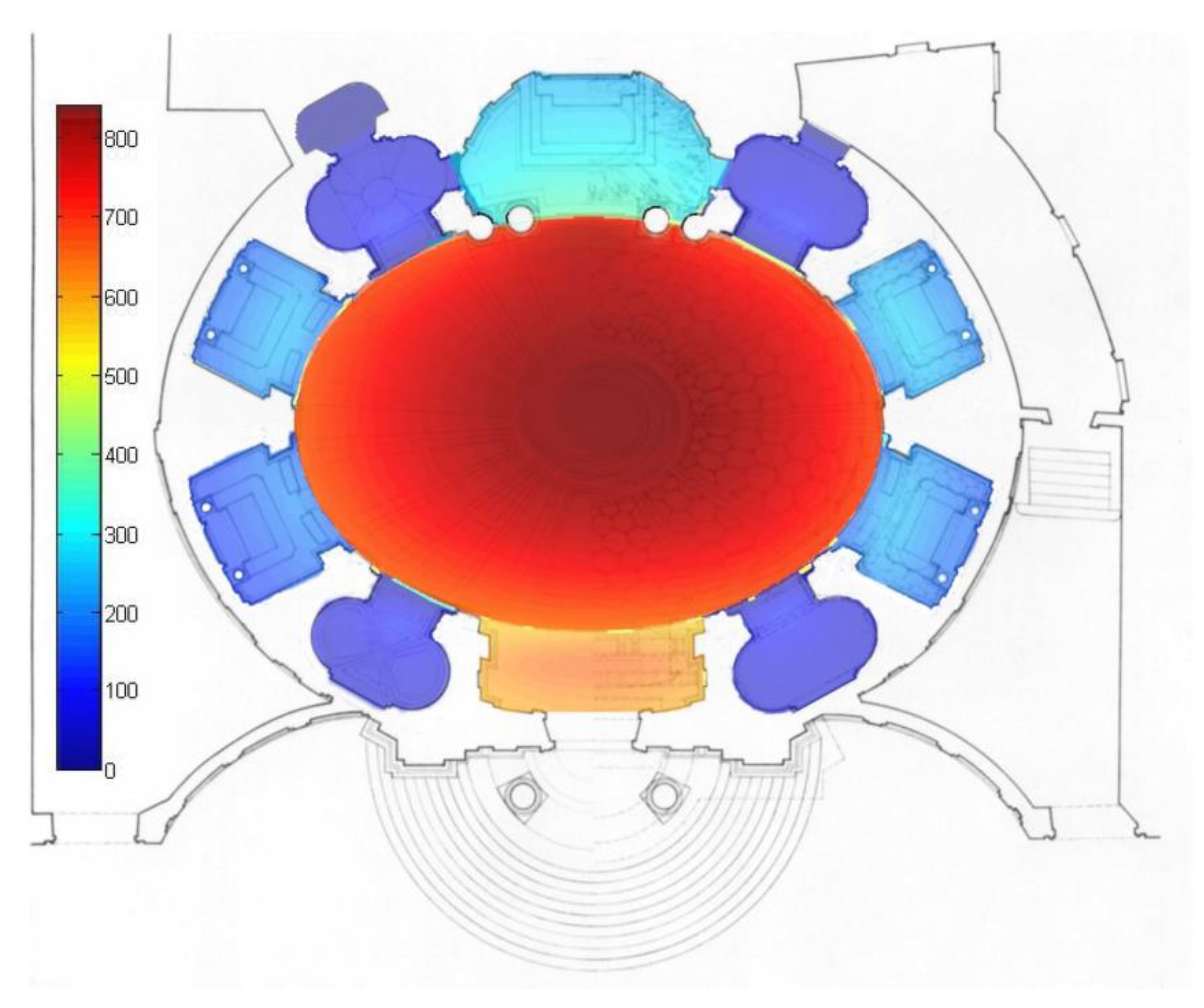
3.1.3. The Church of St. Andrew on the Quirinal (Rome)
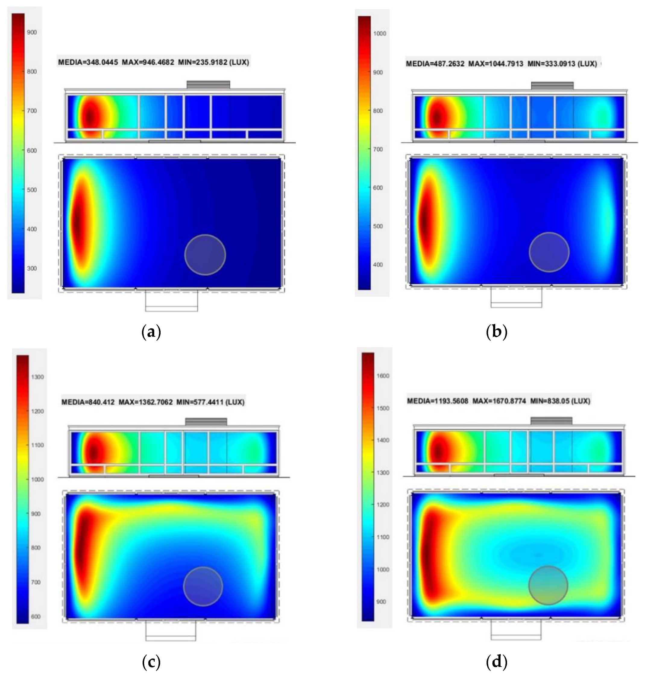
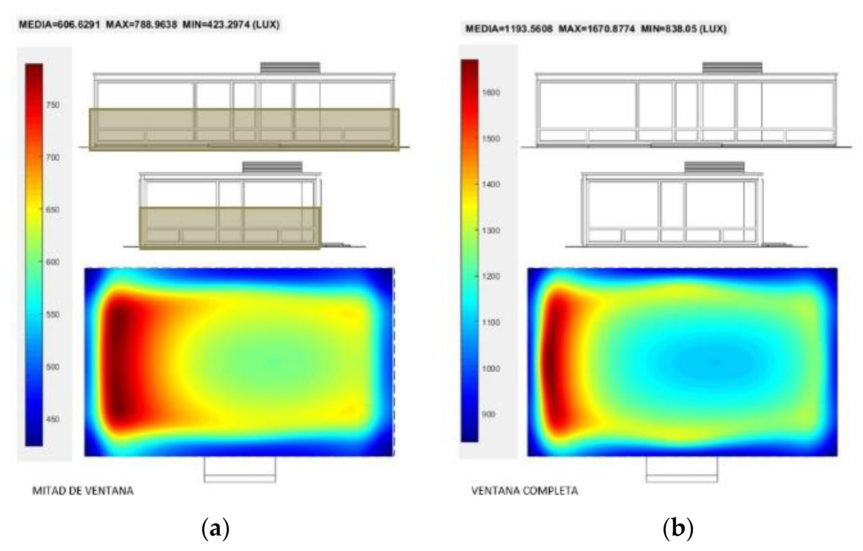
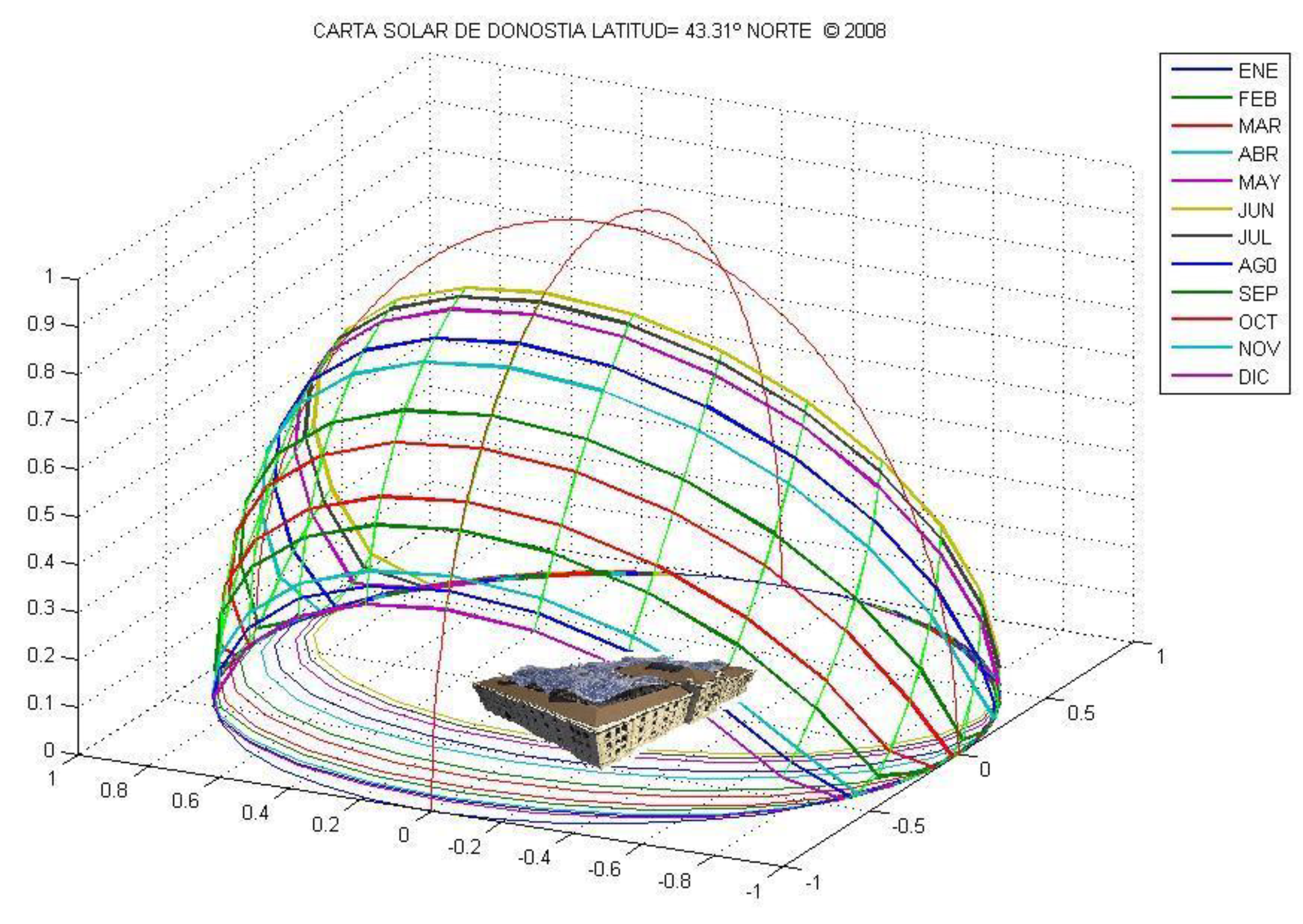
3.2. Simulations of Contemporary Buildings by A. Aalto and P. Johnson
3.3. Simulations of Architectural Projects
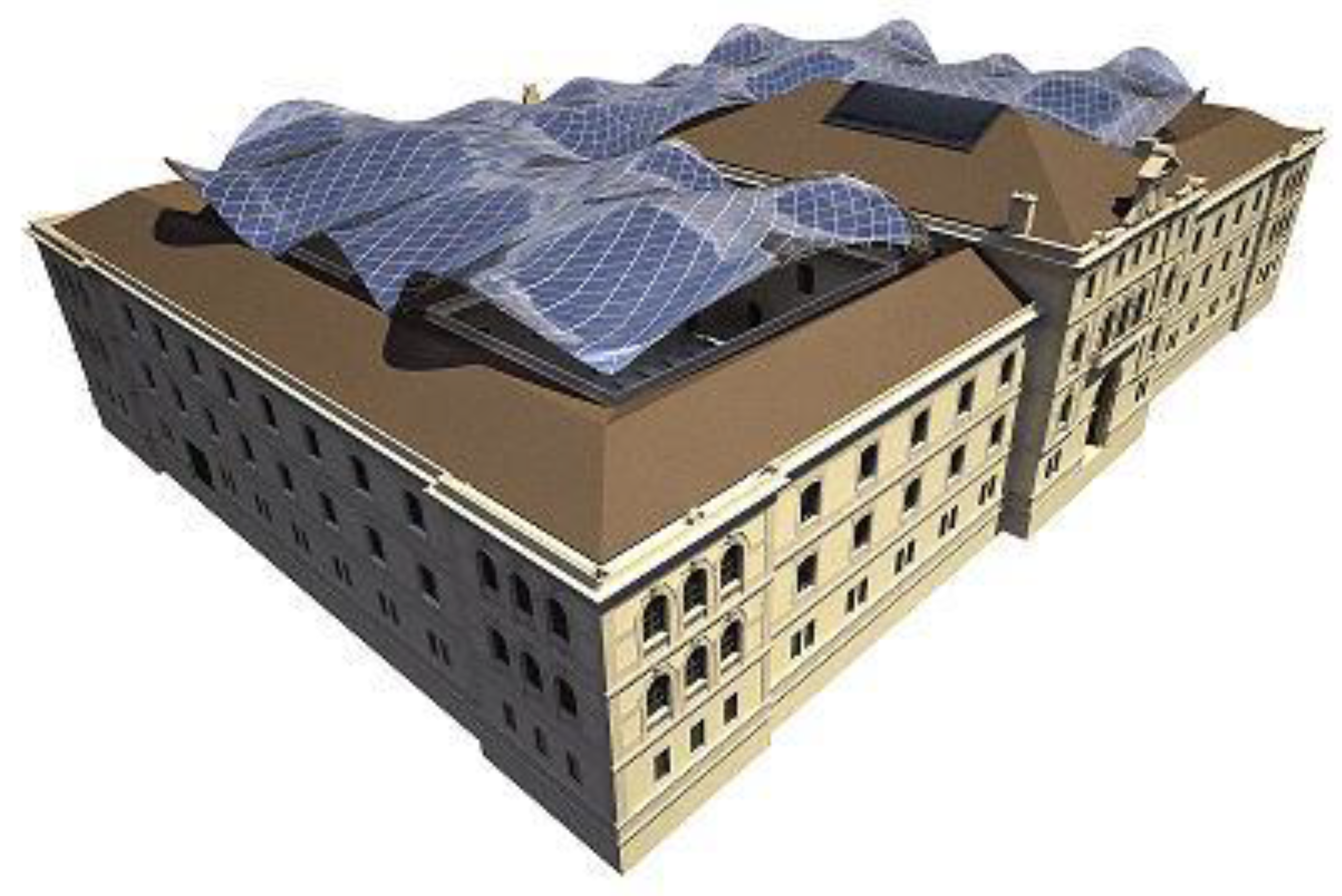
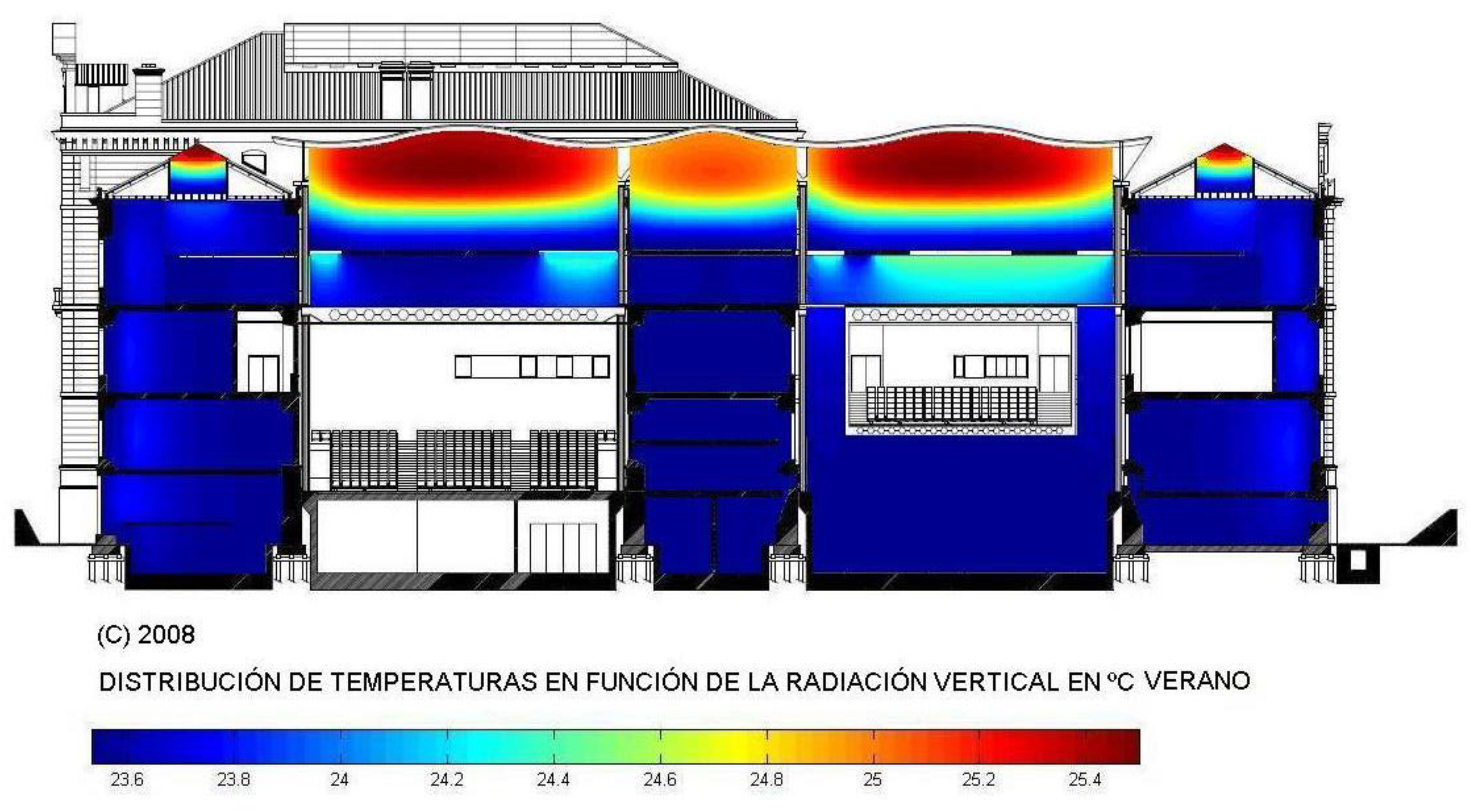
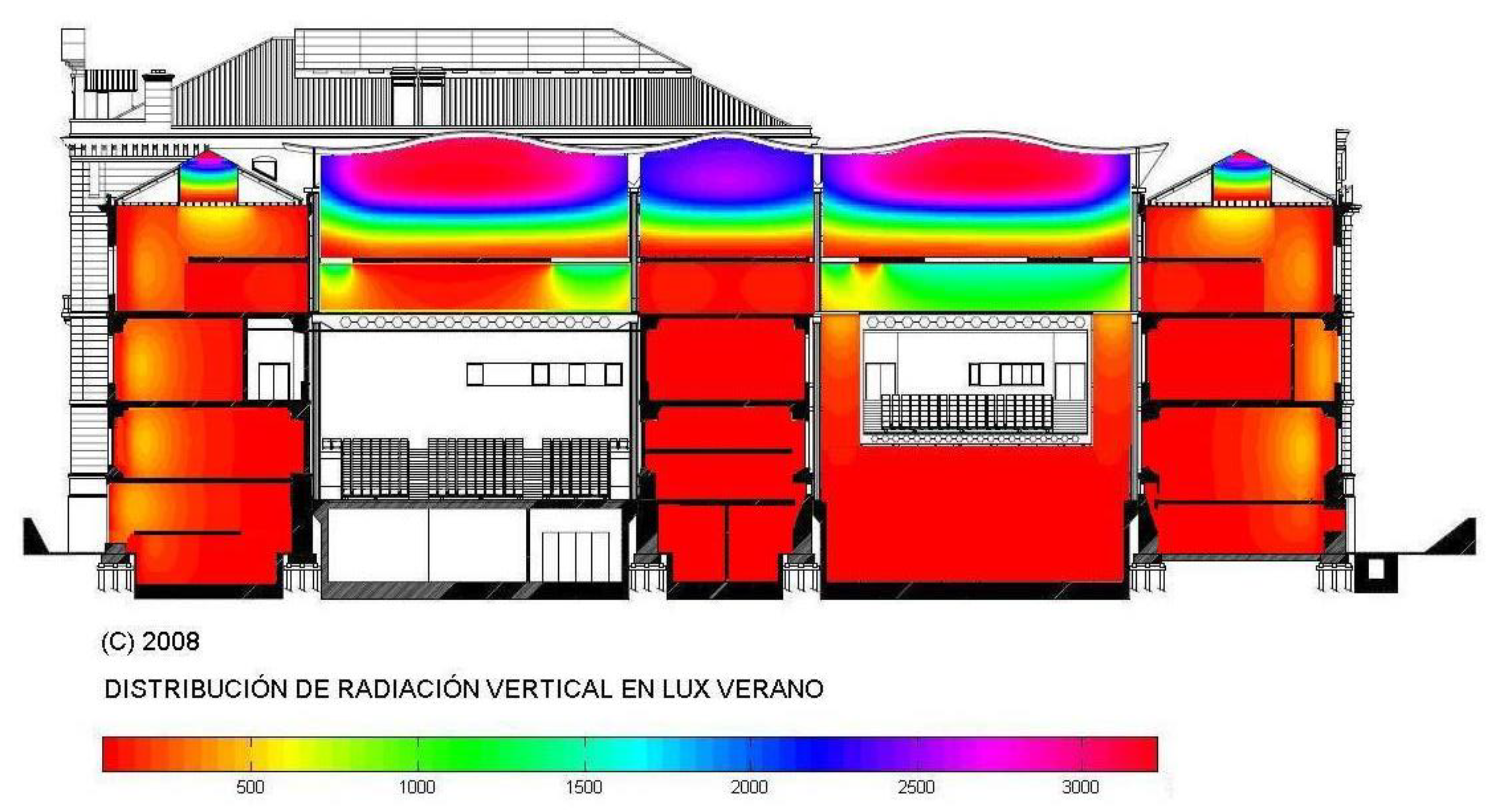
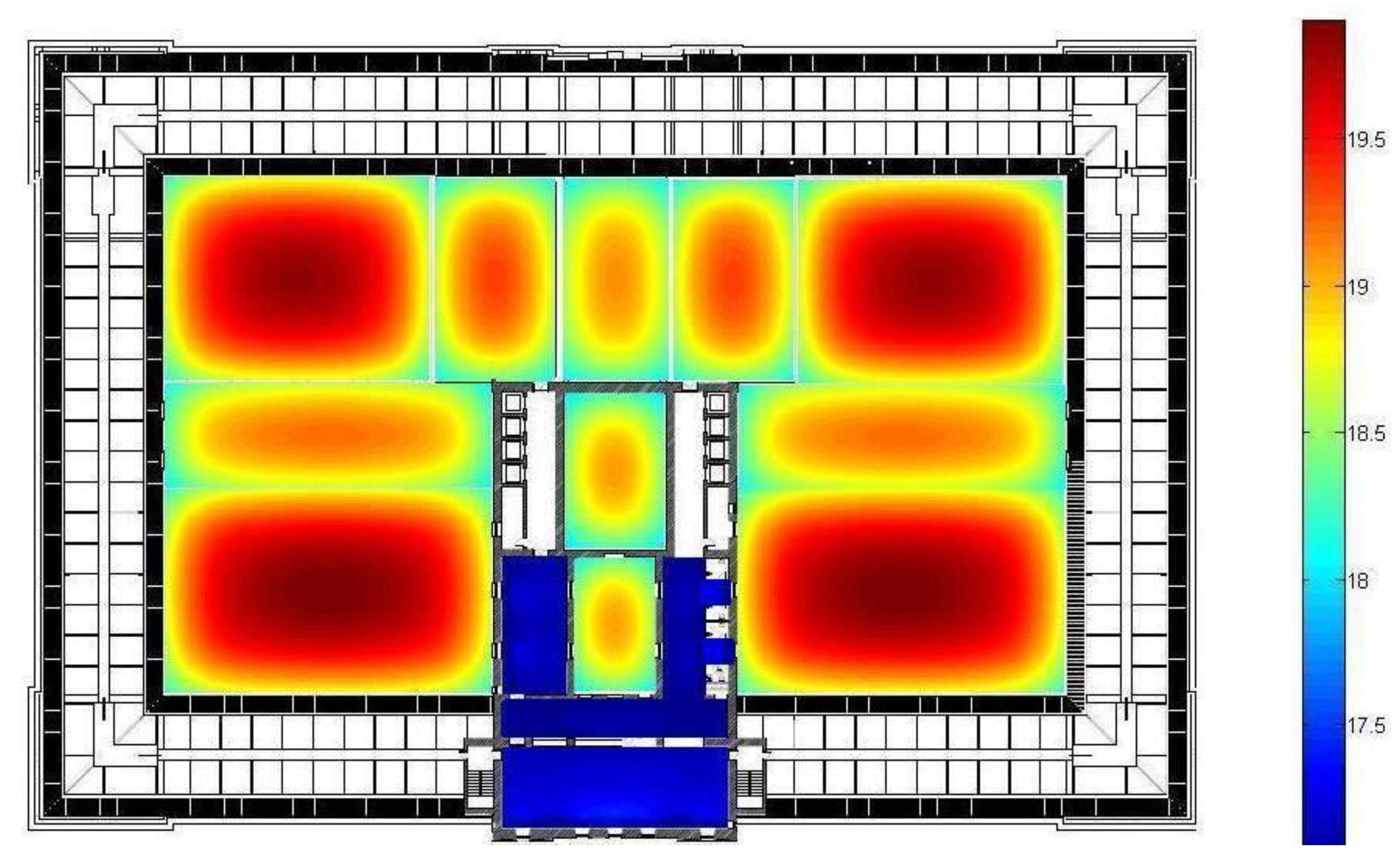
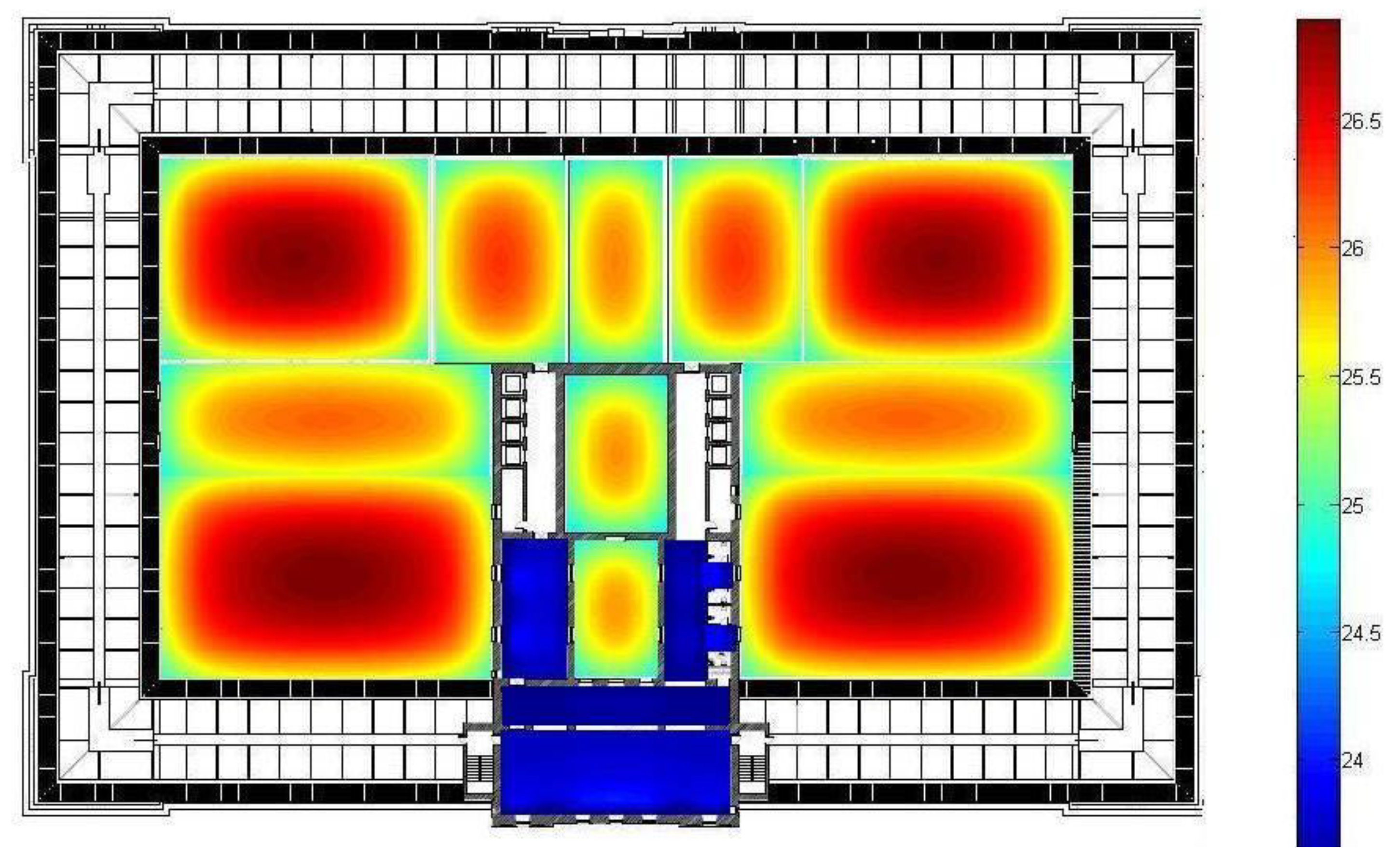
3.3.1. Conversion Project of an Old Tobacco Factory in Donosti (San Sebastian) into a New Cultural Center Called Tabakalera
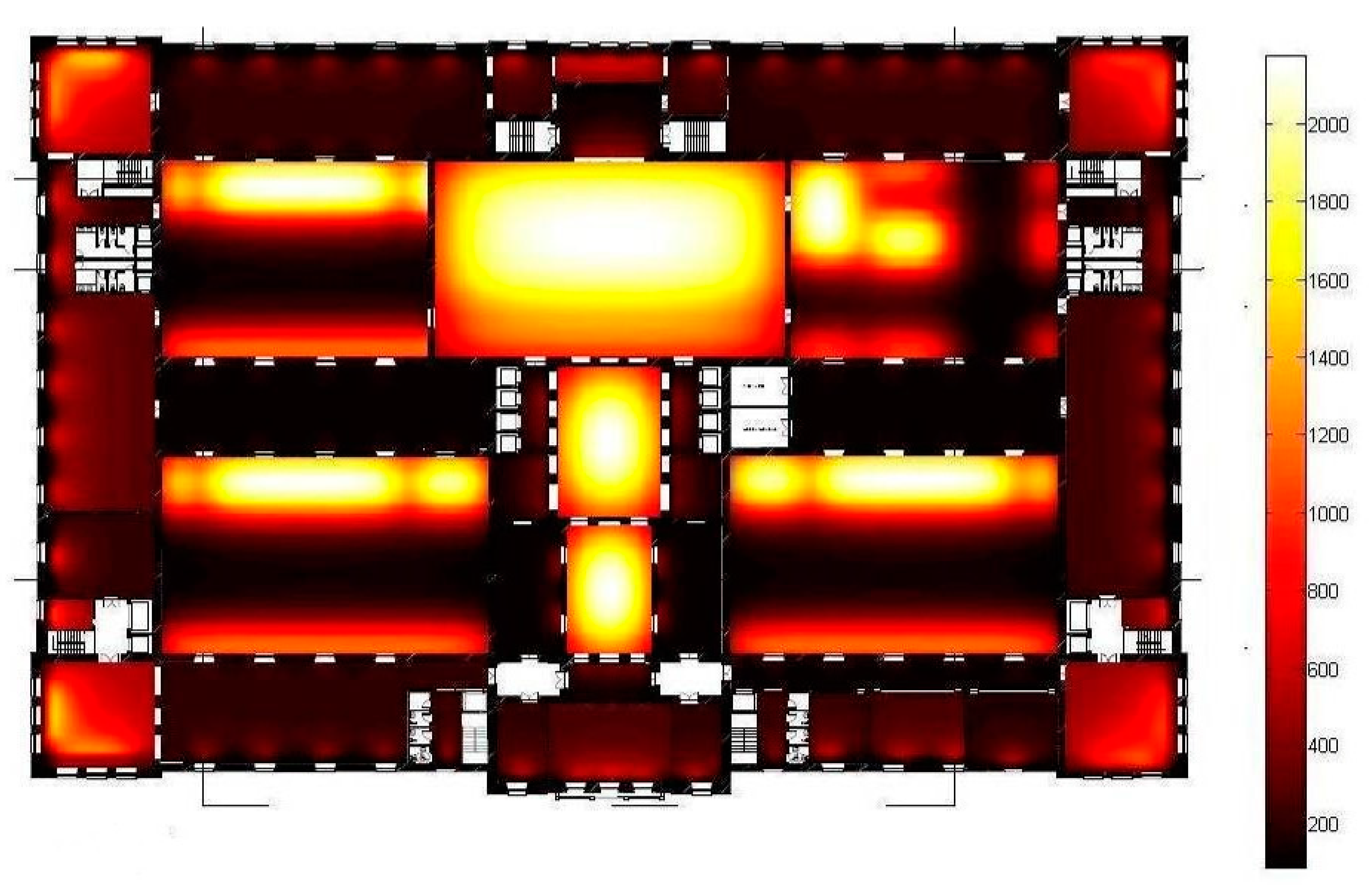
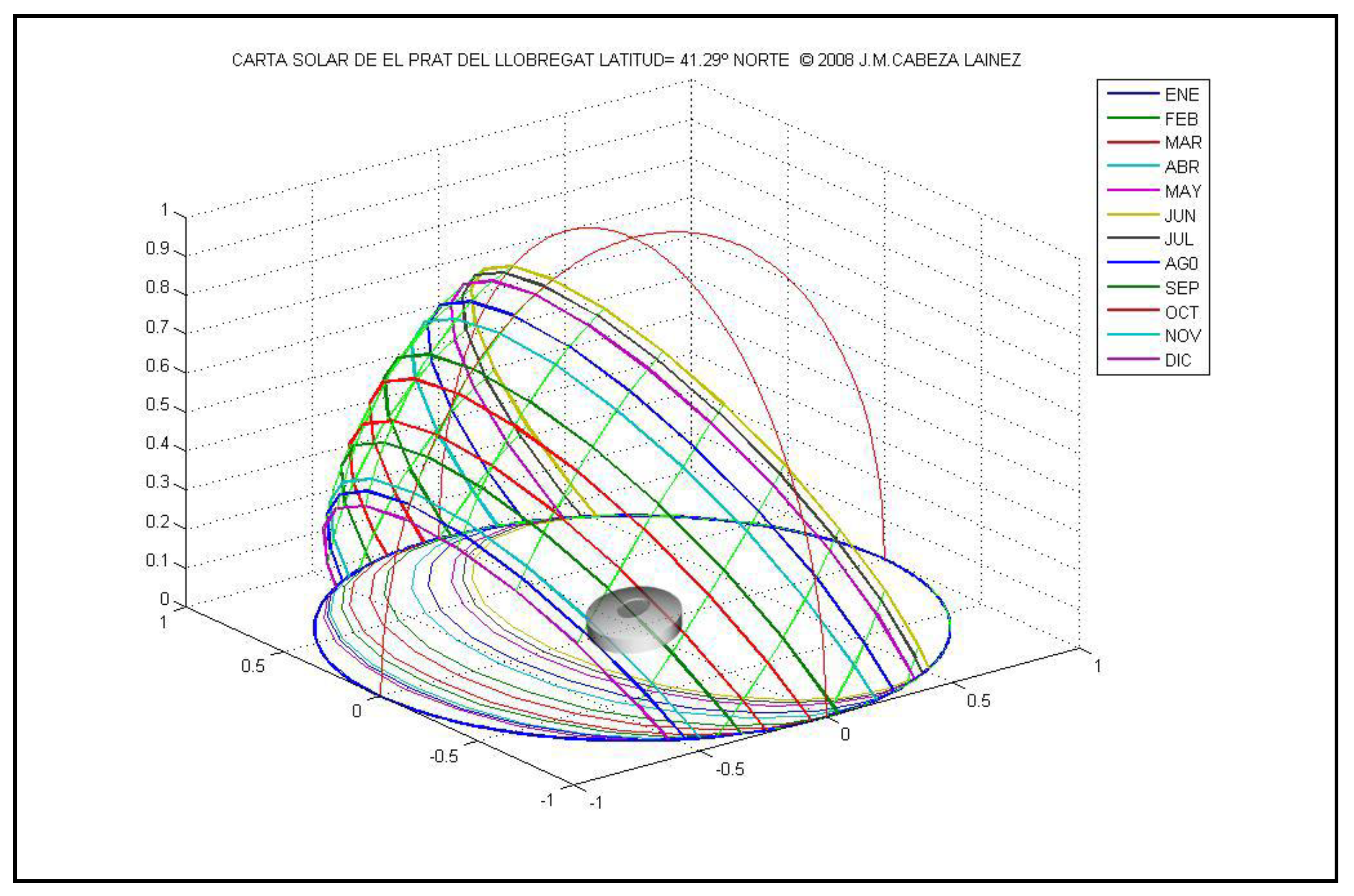
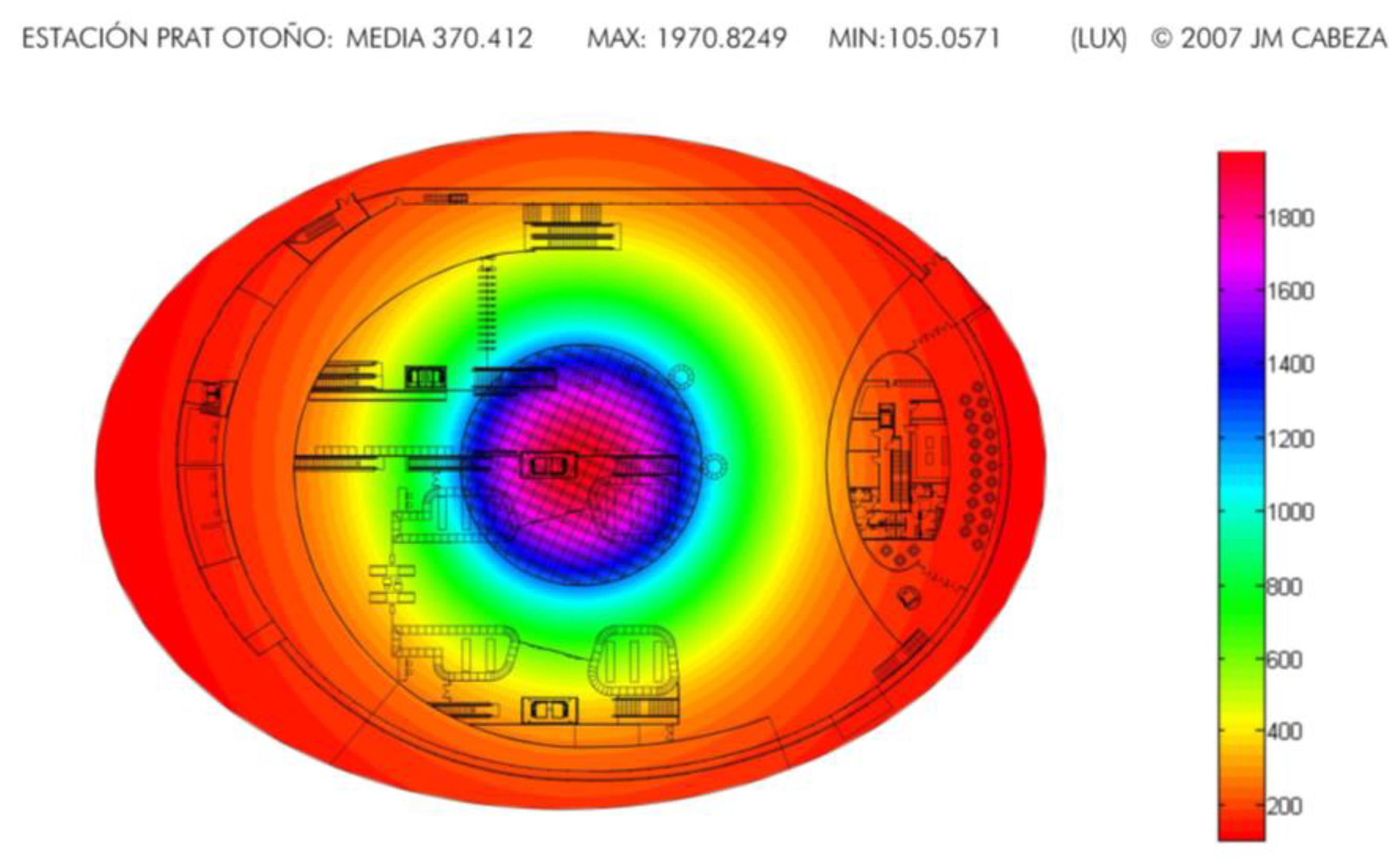
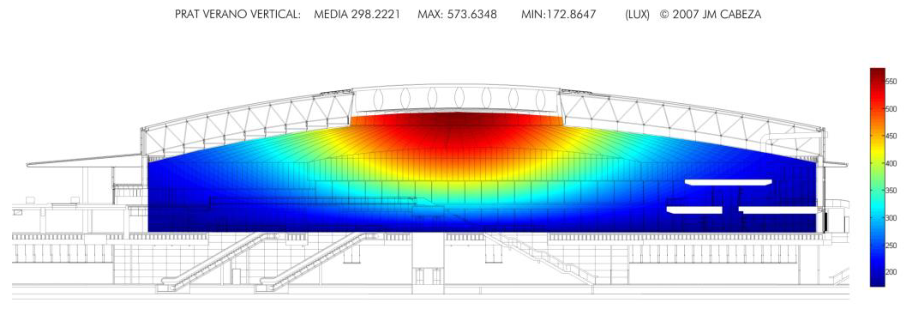
3.3.2. Project for a Transport Hub at Barcelona Airport
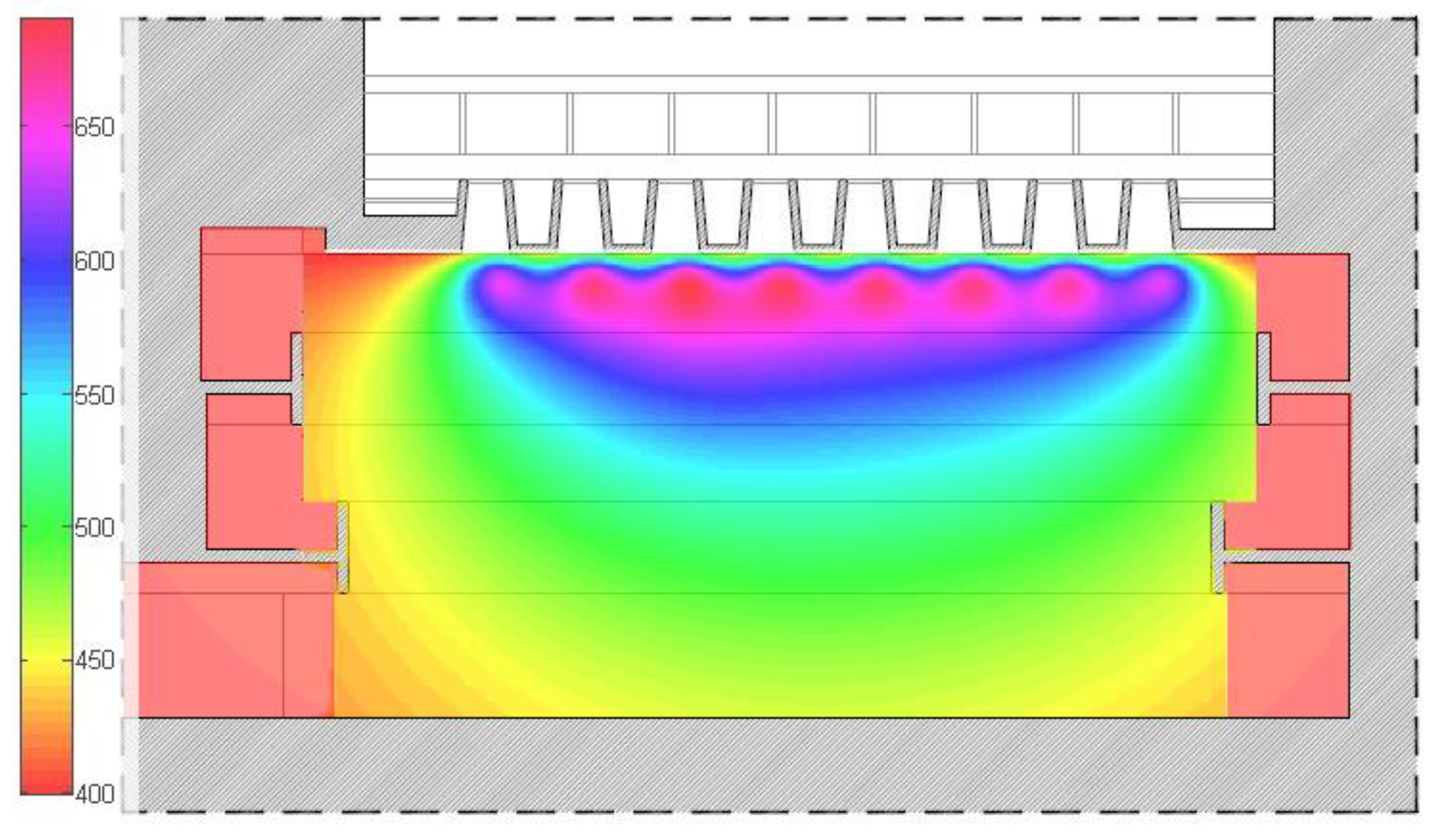
3.3.3. Artificial Lighting of School Comparing Two Types of Luminaires and Our SOFTWARE against Lightscape 3.2
- 1
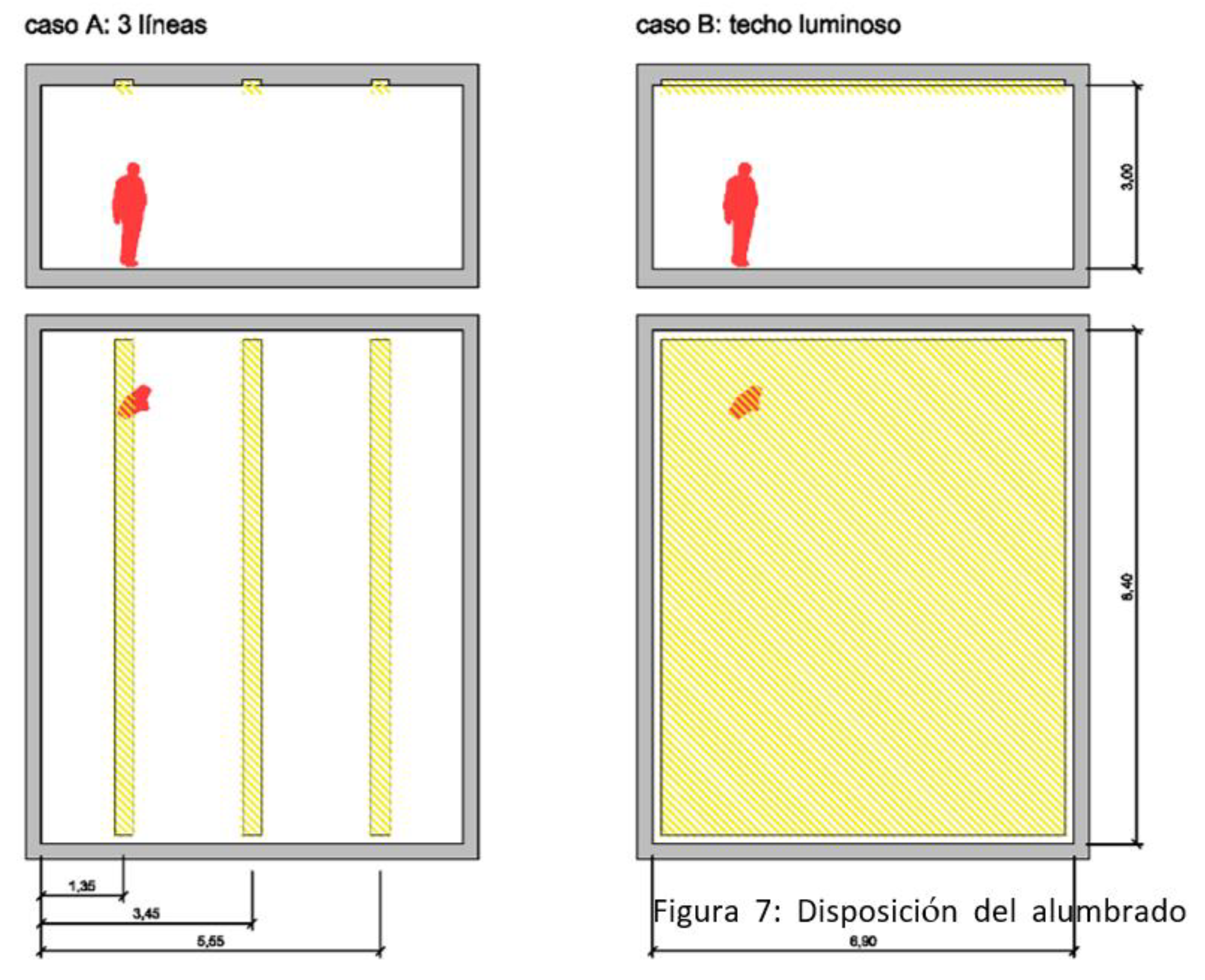
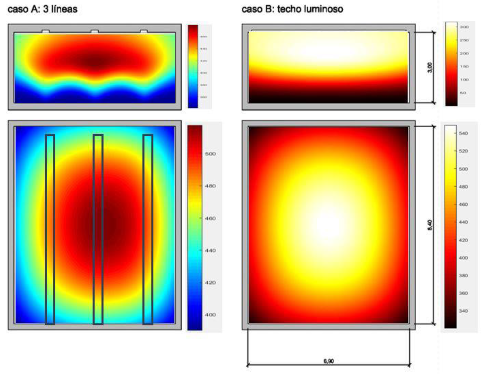
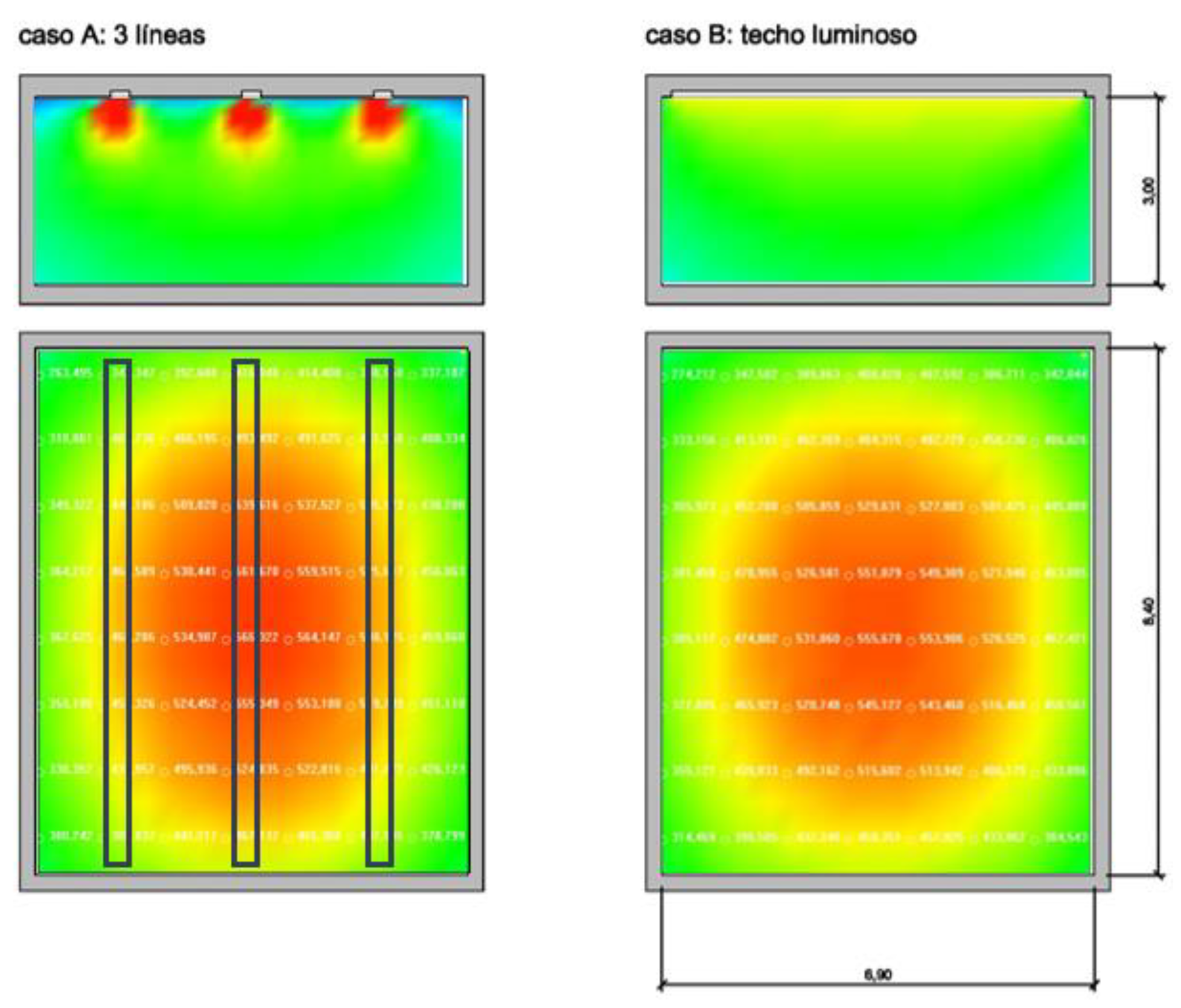
- Linear lighting. Three line fixtures of luminaires are set on the ceiling and orientated longitudinally and parallel to the wider side of the room. The dimensions of such lines are fixed at 0.30 m. by 8.40 m and 12,600 lumens. In the classroom, there are three lines 2.1 m apart from axis to axis and centred with respect to the Y-axis (Figure 25).
- 2
- Surface source. A luminaire covering the whole breadth of the ceiling is proposed with dimensions 6.9 m by 8.40 m and to a height of 3 m. This luminaire has 37,800 lm.
4. Discussion
Author Contributions
Funding
Institutional Review Board Statement
Informed Consent Statement
Data Availability Statement
Acknowledgments
Conflicts of Interest
References
- Cabeza-Lainez, J.M. Fundamentos de Transferencia Radiante Luminosa o La Verdadera Naturaleza del Factor de Forma y sus Modelos de Cálculo; Netbiblio: Seville, Spain, 2010. [Google Scholar]
- Ashdown, I. Radiative Transfer Networks Revisited. J. Illum. Eng. Soc. 2001, 1, 38–51. [Google Scholar] [CrossRef]
- Lambert, J.H. Photometri: Sive de Mensura et Gradibus Luminis, Colorum et Umbrae; DiLaura, D., Ed.; IESNA: New York, NY, USA, 2001. [Google Scholar]
- Holman, J.P. Heat Transfer; Mac Graw-Hill: New York, NY, USA, 1997. [Google Scholar]
- Sasaki, K.; Sznajder, M. Analytical view factor solutions of a spherical cap from an infinitesimal surface. Int. J. Heat Mass Transf. 2020, 163, 120477. [Google Scholar] [CrossRef]
- Cabeza-Lainez, J.M.; Pulido-Arcas, J.A. New configuration factors for curved surfaces. J. Quant. Spectrosc. Radiat. Transf. 2013, 111, 71–80. [Google Scholar] [CrossRef]
- Cabeza-Lainez, J. Architectural Characteristics of Different Configurations Based on New Geometric Determinations for the Conoid. Buildings 2022, 12, 10. [Google Scholar] [CrossRef]
- Almodovar-Melendo, J.-M.; Cabeza-Lainez, J.-M.; Rodriguez-Cunill, I. Lighting Features in Historical Buildings: Scientific Analysis of the Church of Saint Louis of the Frenchmen in Sevilla. Sustainability 2018, 10, 3352. [Google Scholar] [CrossRef]
- DiLaura, D.L. New Procedures for Calculating Diffuse and Non-Diffuse Radiative Exchange Form Factors; ASME: New York, NY, USA, 1999. [Google Scholar]
- Cabeza-Lainez, J.M. The Quest for Light in Indian architectural heritage. J. Asian Archit. Build. Eng. 2008, 7, 39–46. [Google Scholar] [CrossRef]
- Almodóvar-Melendo, J.M.; Cabeza-Lainez, J.M. Nineteen thirties architecture for tropical countries: Le Corbusier’s brise-soleil at the Ministry of Education in Rio de Janeiro. J. Asian Archit. Build. Eng. 2008, 7, 9–14. [Google Scholar] [CrossRef]
- Revenga Domínguez, P. Barroco; Grupo Cultural Ediciones: Madrid, Spain, 2008; ISBN 978-84-8369-099-4. [Google Scholar]
- Revenga Domínguez, P. Un alboroto magnífico. In Palas y las Musas. Diálogos entre la Ciencia y el Arte; México, D.F., Ed.; Siglo XXI: Mexico DF, Mexico, 2016; Volume 2, ISBN 978-607-03-0782-9. [Google Scholar]
- Cabeza-Lainez, J.M.; Almodóvar-Melendo, J.M. Daylight, Shape, and Cross-Cultural Influences through the Routes of Discoveries: The Case of Baroque Temples. Space Cult. 2018, 21, 340–357. [Google Scholar] [CrossRef]
- Cabeza-Lainez, J.; Almodovar-Melendo, J.-M.; Dominguez, I. Daylight and Architectural Simulation of the Egebjerg School (Denmark): Sustainable Features of a New Type of Skylight. Sustainability 2019, 11, 5878. [Google Scholar] [CrossRef]
- Salguero-Andújar, F.; Cabeza-Lainez, J.-M. New Computational Geometry Methods Applied to Solve Complex Problems of Radiative Transfer. Mathematics 2020, 8, 2176. [Google Scholar] [CrossRef]
- Cabeza-Lainez, J.M.; Salguero-Andújar, F.; Rodríguez-Cunill, I. Prevention of Hazards Induced by a Radiation Fireball through Computational Geometry and Parametric Design. Mathematics 2022, 10, 387. [Google Scholar] [CrossRef]
- Salguero-Andújar, F.; Prat-Hurtado, F.; Rodriguez-Cunill, I.; Cabeza-Lainez, J. Architectural Significance of the Seokguram Buddhist Grotto in Gyeongju (Korea). Buildings 2022, 12, 3. [Google Scholar] [CrossRef]
- Rubio-Bellido, C.; Pulido-Arcas, J.A.; Cabeza-Lainez, J.M. Understanding climatic traditions: A quantitative and qualitative analysis of historic dwellings of Cadiz. Indoor Built Environ. 2018, 27, 665–681. [Google Scholar] [CrossRef]
- Moore, F. Concepts and Practice of Architectural Daylighting; Van Nostrand Reinhold: New York, NY, USA, 1991. [Google Scholar]
- Modest, M.F. View Factors. In Radiative Heat Transfer, 3rd ed.; Academic Press: Boston, MA, USA, 2013; pp. 129–159. [Google Scholar]
- Petty, M. “The Edge of Danger”: Artificial lighting and the dialectics of domestic occupation in Philip Johnson’s Glass and Guest Houses. In Proceedings of the Occupation: Negotiations with Constructed Space, Brighton, UK, 2–4 July 2009. [Google Scholar]
- Moon, P.H.; Spencer, D.E. The Photic Field; The MIT Press: Cambridge, MA, USA, 1981. [Google Scholar]
- Robbins, C.L. Daylighting. In Design and Analysis; Van Nostrand Reinhold: New York, NY, USA, 1986. [Google Scholar]
- Charles, P.P.; Thomas, C.R. Building performance simulation in undergraduate multidisciplinary education: Learning from an architecture and engineering collaboration. In Proceedings of the Building Simulation, Glasgow, Scotland, 27–30 July 2009. [Google Scholar]
- William, M.C.L. Perception and Lighting as Formgivers for Architecture; McGraw-Hill: New York, NY, USA, 1977. [Google Scholar]
- Cabeza Lainez, J.M. Solar Radiation in Buildings, Transfer and Simulation Procedures; Babatunde, E.B., Ed.; InTech: Rijeka, Croatia, 2012; ISBN 978-953-51-0384-4. [Google Scholar]
- Ashdown, I. Radiosity: A Programmer’s Perspective; John Wiley & Sons Inc.: New York, NY, USA, 1994; Available online: http://www.helios32.com (accessed on 22 July 2021).
- MacAllister, A.S. Graphical Solutions of Problems Involving Plane-Surface Lighting Sources. Lighting World 1910, 56, 17–24. [Google Scholar]
- Ne’eman, E. Visual Aspects of Sunlight in Buildings. Lighting Res. Technol. 1974, 6, 159–164. [Google Scholar] [CrossRef]
- Yamauchi, J. Theory of Field of Illumination. Res. Electro-Tech. Lab. 1932, 2, 3–16. [Google Scholar]
- Hopkinson, R.G.; Petherbridge, P.; Longmore, J. Daylighting; Heinemann: London, UK, 1966. [Google Scholar]
- Moon, P.H. The Scientific Basis of Illuminating Engineering; Dover Publications: New York, NY, USA, 1962. [Google Scholar]
- Yamauchi, J. The Light Flux Distribution of a System of Inter-Reflecting Surfaces. Res. Electro-Tech. Lab. 1927, 3, 11–18. (In Japanese) [Google Scholar]
- Almodóvar-Melendo, J.-M.; Quesada-García, S.; Valero-Flores, P.; Cabeza-Lainez, J. Solar Radiation in Architectural Projects as a Key Design Factor for the Well-Being of Persons with Alzheimer’s Disease. Buildings 2022, 12, 603. [Google Scholar] [CrossRef]
- Almodovar-Melendo, J.M.; La Roche, P. Roof ponds combined with a water-to-air heat exchanger as a passive cooling system: Experimental comparison of two system variants. Renew. Energy 2019, 141, 195–208. [Google Scholar] [CrossRef] [Green Version]
- Berque, A. La Rizière et la Banquise; Colonisation et Changement Culturel a Hokkaido; Publications Orientalistes de France: Paris, France, 1980. [Google Scholar]
- Berque, A. Poetique de la Terre-Histoire Naturelle; Belin: Paris, France, 2014. [Google Scholar]
- Yamauchi, J. The Amount of Flux Incident to Rectangular Floor through Rectangular Windows; Researches of the Electro-Technical Laboratory: Tokyo, Japan, 1929; No. 250. [Google Scholar]


| 3 lines (0.30 × 8.40 m) | surface (6.90 × 8.40 m) |
| 12600 lm each line | 37800 lm surface |
| 5000 lx each line | 652.17 lux surface |
| Reflection 0.70 0.50 0.20 | Reflection 0.30 0.50 0.20 (reflection from the ceiling = translucent glazing 30%) |
| Em [lx] 466 | Em [lx] 454 |
| Emin [lx] 390 | Emin [lx] 320 |
| Emax [lx] 518 | Emax [lx] 550 |
| Emin/Em 0.837 | Emin/Em 0.706 |
| Em [lx] 452 | Em [lx] 452 |
| Emin [lx] 221 | Emin [lx] 230 |
| Emax [lx] 571 | Emax [lx] 559 |
| Emin/Em 0.489 | Emin/Em 0.509 |
Publisher’s Note: MDPI stays neutral with regard to jurisdictional claims in published maps and institutional affiliations. |
© 2022 by the authors. Licensee MDPI, Basel, Switzerland. This article is an open access article distributed under the terms and conditions of the Creative Commons Attribution (CC BY) license (https://creativecommons.org/licenses/by/4.0/).
Share and Cite
Cabeza-Lainez, J.; Almodóvar-Melendo, J.-M.; Revenga-Dominguez, P.; Rodríguez-Cunill, I.; Xu, Y. New Simulation Tool for Architectural Design in the Realm of Solar Radiative Transfer. Designs 2022, 6, 72. https://doi.org/10.3390/designs6050072
Cabeza-Lainez J, Almodóvar-Melendo J-M, Revenga-Dominguez P, Rodríguez-Cunill I, Xu Y. New Simulation Tool for Architectural Design in the Realm of Solar Radiative Transfer. Designs. 2022; 6(5):72. https://doi.org/10.3390/designs6050072
Chicago/Turabian StyleCabeza-Lainez, Joseph, Jose-Manuel Almodóvar-Melendo, Paula Revenga-Dominguez, Inmaculada Rodríguez-Cunill, and Yingying Xu. 2022. "New Simulation Tool for Architectural Design in the Realm of Solar Radiative Transfer" Designs 6, no. 5: 72. https://doi.org/10.3390/designs6050072