
The Influence of Nusselt Correlation on Exergy Efficiency of a Plate Heat Exchanger Operating with TiO2:SiO2/EG:DI Hybrid Nanofluid

Abstract
:1. Introduction
2. Thermal Performance Analysis
3. Methodology
4. Results and Discussion
5. Conclusions
Funding
Data Availability Statement
Conflicts of Interest
Nomenclature
| A | extended heat transfer area |
| c | specific heat |
| C | heat capacity |
| D | hydrodynamic channel diameter |
| thermal energy exchanged by convection and conduction | |
| f | friction factor |
| G | mass flow rate |
| h | heat transfer coefficient |
| k | conductive heat transfer coefficient |
| high of PHE | |
| heat transfer rate | |
| average heat flux | |
| heat transfer coefficient | |
| total entropy generation | |
| thermal entropy | |
| friction entropy | |
| Ta | ambient temperature |
| Tw,ex | external surface temperature |
| temperatures of the working fluid at the input and output of the heat exchanger | |
| u | standard uncertainty |
| volumetric flow | |
| volume or weight concentration of the suspension | |
| ε | efficiency |
| density | |
| dynamic viscosity | |
| exergy efficiency | |
| indexes | |
| c | cold |
| h | hot |
| nf | nanofluid |
| bf | base liquid |
| wf | working fluid |
| Abbreviations | |
| PHE | plate heat exchanger |
| DI | deionised water |
| Nu, Pr, Re | Nusselt, Prandtl, and Reynolds numbers, respectively |
| NTU | Number of Transfer Units |
References
- Karapidakis, E.; Kalogerakis, C.; Pompodakis, E. Sustainable Power Generation Expansion in Island Systems with Extensive RES and Energy Storage. Inventions 2023, 8, 127. [Google Scholar] [CrossRef]
- Mukherjee, S.; Wciślik, S.; Ebrahim, S.; Alsayegh, N. Enhancing cooling performance of a heat exchanger driven by water/alumina-silica hybrid nanofluid: Experimental results. J. Enhanc. Heat Transf. 2024, 31, 21–47. [Google Scholar] [CrossRef]
- Zheng, D.; Du, J.; Wang, W.; Klemeš, J.J.; Wang, J.; Sundén, B. Analysis of thermal efficiency of a corrugated double-tube heat exchanger with nanofluids. Energy 2022, 256, 124522. [Google Scholar] [CrossRef]
- Alklaibi, A.M.; Sundar, L.S.; Kotturu, V.V.; Mouli, C. Experimental investigation on the performance of hybrid Fe3O4 coated MWCNT/Water nanofluid as a coolant of a Plate heat exchanger. Int. J. Therm. Sci. 2022, 171, 107249. [Google Scholar] [CrossRef]
- YousefiMiab, E.; Islami, S.B.; Gharraei, R. Feasibility assessment of using nanofluids in shell and tube heat exchanger of gas pressure reducing stations through a new developed OpenFOAM solver. Int. J. Heat Fluid Flow 2022, 96, 108985. [Google Scholar] [CrossRef]
- Available online: https://www.sciencedirect.com/search?qs=nanofluids%2C%20plate%20heat%20exchanger&lastSelectedFacet=years (accessed on 22 September 2023).
- Wciślik, S.; Mukherjee, S. Evaluation of three methods of static contact angle measurements for TiO2 nanofluid droplets during evaporation. Phys. Fluids 2022, 34, 062006. [Google Scholar] [CrossRef]
- Jafarimoghaddam, A.; Aberoumand, S. An empirical investigation on Cu/Ethylene Glycol nanofluid through a concentric annular tube and proposing a correlation for predicting Nusselt number. Alex. Eng. J. 2016, 55, 1047–1052. [Google Scholar] [CrossRef]
- Asadi, A.; Asadi, M.; Rezaniakolaei, A.; Rosendahl, L.A.; Afrand, M.; Wongwises, S. Heat transfer efficiency of Al2O3-MWCNT/thermal oil hybrid nanofluid as a cooling fluid in thermal and energy management applications: An experimental and theoretical investigation. Int. J. Heat Mass Transf. 2018, 117, 474–486. [Google Scholar] [CrossRef]
- Wciślik, S. Efficient Stabilization of Mono and Hybrid Nanofluids. Energies 2020, 13, 3793. [Google Scholar] [CrossRef]
- Okonkwo, E.C.; Wole-Osho, I.; Almanassra, I.W.; Abdullatif, Y.M.; Al-Ansari, T. An updated review of nanofluids in various heat transfer devices. J. Therm. Anal. Calorim. 2021, 145, 2817–2872. [Google Scholar] [CrossRef]
- Wciślik, S. A simple economic and heat transfer analysis of the nanoparticles use. Chem. Pap. 2017, 71, 2395–2401. [Google Scholar] [CrossRef]
- Mukherjee, S.; Wciślik, S.; Khadanga, V.; Mishra, P.C. Influence of nanofluids on the thermal performance and entropy generation of varied geometry microchannel heat sink. Case Stud. Therm. Eng. 2023, 49, 103241. [Google Scholar] [CrossRef]
- Mercan, H. Chapter 3-Thermophysical and rheological properties of hybrid nanofluids. In Hybrid Nanofluids for Convection Heat Transfer; Ali, H.M., Ed.; Academic Press: Cambridge, MA, USA, 2020; pp. 101–142. [Google Scholar] [CrossRef]
- Wohld, J.; Beck, J.; Inman, K.; Palmer, M.; Cummings, M.; Fulmer, R.; Vafaei, S. Hybrid Nanofluid Thermal Conductivity and Optimization: Original Approach and Background. Nanomaterials 2022, 12, 2847. [Google Scholar] [CrossRef]
- Fattahi, M.; Khakrah, H.; Jamalabadi, M.Y.A.; Bagheri, N.; Ross, D. Cooling of an electronic package using lattice Boltzmann/finite volume method with experimental rheological/thermal analysis of hybrid nanofluid properties. J. Mol. Liq. 2020, 299, 112143. [Google Scholar] [CrossRef]
- Akhgar, A.; Toghraie, D. An experimental study on the stability and thermal conductivity of water-ethylene glycol/TiO2-MWCNTs hybrid nanofluid: Developing a new correlation. Powder Technol. 2018, 338, 806–818. [Google Scholar] [CrossRef]
- Desisa, T.R. Experimental and numerical investigation of heat transfer characteristics in solar flat plate collector using nanofluids. Int. J. Thermofluids 2023, 18, 100325. [Google Scholar] [CrossRef]
- Nartowska, E.; Styś-Maniara, M.; Kozłowski, T. The Potential Environmental and Social Influence of the Inorganic Salt Hydrates Used as a Phase Change Material for Thermal Energy Storage in Solar Installations. Int. J. Environ. Res. Public Health 2023, 20, 1331. [Google Scholar] [CrossRef] [PubMed]
- Nkurikiyimfura, I.; Wang, Y.; Safari, B.; Nshingabigwi, E. Electrical and thermal performances of photovoltaic/thermal systems with magnetic nanofluids: A review. Particuology 2021, 54, 181–200. [Google Scholar] [CrossRef]
- Mehdizadeh-Fard, M.; Pourfayaz, F.; Maleki, A. Exergy analysis of multiple heat exchanger networks: An approach based on the irreversibility distribution ratio. Energy Rep. 2021, 7, 174–193. [Google Scholar] [CrossRef]
- Tong, Y.; Lee, H.; Kang, W.; Cho, H. Energy and exergy comparison of a flat-plate solar collector using water, Al2O3 nanofluid, and CuO nanofluid. Appl. Therm. Eng. 2019, 159, 113959. [Google Scholar] [CrossRef]
- Ehyaei, M.A.; Ahmadi, A.; Assad, M.E.H.; Hachicha, A.A.; Said, Z. Energy, exergy and economic analyses for the selection of working fluid and metal oxide nanofluids in a parabolic trough collector. Sol. Energy 2019, 187, 175–184. [Google Scholar] [CrossRef]
- Iranmanesh, S.; Silakhori, M.; Naghavi, M.S.; Ang, B.C.; Ong, H.C.; Esmaeilzadeh, A. Using Graphene Nanoplatelets Nanofluid in a Closed-Loop Evacuated Tube Solar Collector—Energy and Exergy Analysis. J. Compos. Sci. 2021, 5, 277. [Google Scholar] [CrossRef]
- Orzechowski, T.; Stokowiec, K. Quasi-stationary phase change heat transfer on a fin. EPJ Web Conf. 2016, 114, 02086. [Google Scholar] [CrossRef]
- Purohit, N.; Purohit, V.A.; Purohit, K. Assessment of nanofluids for laminar convective heat transfer: A numerical study. Eng. Sci. Technol. Int. J. 2016, 19, 574–586. [Google Scholar] [CrossRef]
- Akturk, F.; Sezer-Uzol, N.; Aradag, S.; Kakac, S. Experimental investigation and performance analysis of gasketed-plate heat exchangers. J. Therm. Sci. Technol. 2015, 35, 43–52. [Google Scholar]
- Sieder, E.N.; Tate, G.E. Heat transfer and pressure drop of liquids in tubes. Ind. Eng. Chem. 1936, 28, 1429–1439. [Google Scholar] [CrossRef]
- Kumar, H. Evaporation in Plate Heat Exchangers; AIChE: New York, NY, USA, 1993. [Google Scholar]
- Focke, W.W.; Zacharides, J.; Oliver, I. The effect of the corrugation inclination angle on the thermohydraulic performance of the plate heat exchangers. Int. J. Heat Mass Transf. 1985, 28, 1469–1479. [Google Scholar] [CrossRef]
- Okada, K.; Ono, M.; Tomimura, T.; Okuma, T.; Konno, H.; Ohtani, S. Design and heat transfer characteristics of a new plate heat exchanger. Heat Transf. Jpn. Res. 1972, 1, 90–95. [Google Scholar]
- Kakac, S.; Liu, H. Heat Exchangers. In Selection, Rating and Thermal Design, 2nd ed.; CRC Press: Boca Raton, FL, USA, 2002. [Google Scholar]
- Neagu, A.A.; Koncsag, C.I.; Barbulescu, A.; Botez, E. Calculation methods for gasket plate heat exchangers used in vegetable oil manufacture. Comp. Study Rev. Chim. 2015, 66, 1504–1508. [Google Scholar]
- Al zahrani, S.; Islam, M.S.; Saha, S.C. A thermo-hydraulic characteristics investigation in corrugated plate heat exchanger. Energy Procedia 2019, 160, 597–605. [Google Scholar] [CrossRef]
- Yashawantha, K.M.; Gurjar, G.; Vinod, A.V. Low Temperature Heat Transfer in Plate Heat Exchanger Using Ethylene Glycol–Water Based Al2O3 Nanofluid. Int. J. Thermophys. 2021, 42, 90. [Google Scholar] [CrossRef]
- Guzman-Urbina, A.; Fukushima, K.; Ohno, H.; Fukushima, Y. Deriving local Nusselt number correlations for heat transfer of nanofluids by genetic programming. Int. J. Therm. Sci. 2023, 192, 108382. [Google Scholar] [CrossRef]
- Vajjha, R.S.; Das, D.K.; Kulkarni, D.P. Development of new correlations for convective heat transfer and friction factor in turbulent regime for nanofluids. Int. J. Heat Mass Transf. 2010, 53, 4607–4618. [Google Scholar] [CrossRef]
- Xuan, Y.; Li, Q. Investigation on convective heat transfer and flow features of nanofluids. J. Heat Transf. 2003, 125, 151–155. [Google Scholar] [CrossRef]
- Li, Q.; Xuan, Y.; Jiang, J.; Xu, J.W. Experimental investigation on flow and convective heat transfer feature of a nanofluid for aerospace thermal management. J. Astronaut. 2005, 26, 391–394. [Google Scholar]
- Lai, W.Y.; Duculescu, B.; Phelan, P.E.; Prasher, R.S. Convective heat transfer with nanofluids in a single 1.02-mm tube. In Proceedings of the ASME International Mechanical Engineering Congress and Exposition (IMECE), Chicago, IL, USA, 5–10 November 2006; pp. 65–76. [Google Scholar]
- Chatys, R.; Orman, Ł.J. Technology and properties of layered composites as coatings for heat transfer enhancement. Mech. Compos. Mater. 2017, 53, 351–360. [Google Scholar] [CrossRef]
- Orman, Ł.J.; Chatys, R. Heat transfer augmentation possibility for vehicle heat exchangers. In Proceedings of the 15th International Conference “Transport Means”, Kaunas, Lithuania, 20–21 October 2011; pp. 9–12. [Google Scholar]
- Kumar, S.; Singh, S.K.; Sharma, D. A Comprehensive Review on Thermal Performance Enhancement of Plate Heat Exchanger. Int. J. Thermophys. 2022, 43, 109. [Google Scholar] [CrossRef]
- Gut, J.A.W.; Pinto, J.M. Optimal configuration design for plate heat exchangers. Int. J. Heat Mass Transf. 2004, 47, 4833–4848. [Google Scholar] [CrossRef]
- Zainon, S.N.M.; Azmi, W.H.; Hamisa, A.H. Thermo-physical Properties of TiO2-SiO2 Hybrid Nanofluids Dispersion with Water/Bio-glycol Mixture. J. Phys. Conf. Ser. 2021, 2000, 012003. [Google Scholar] [CrossRef]
- Viessmann Technical Guide. VITOSOL Flat-Plate Collectors and Vacuum Tube Collectors Flat and Pitched Roof Installation, and Wall Mounting. 5822440 GB. May 2018. Available online: https://viessmanndirect.co.uk/files//faa19e98-f0eb-4b23-98a7-aa3201061e16/1805%20Vitosol%20Technical%20Guide%205822440VPA00013_1.PDF (accessed on 28 June 2023).
- Gilliland, M.W. Energy Analysis: A New Public Policy Tool; Westview Press: Boulder, CO, USA, 1978; p. 101. [Google Scholar]
- Upadhyay, S.; Chandra, L.; Sarkar, J. A generalized Nusselt number correlation for nanofluids, and look-up diagrams to select a heat transfer fluid for medium temperature solar thermal applications. Appl. Therm. Eng. 2021, 190, 116469. [Google Scholar] [CrossRef]
- Ünverdi, M.; Islamoglu, Y. Characteristics of heat transfer and pressure drop in a chevron-type plate heat exchanger with Al2O3/water nanofluids. Therm. Sci. 2017, 21, 97. [Google Scholar] [CrossRef]


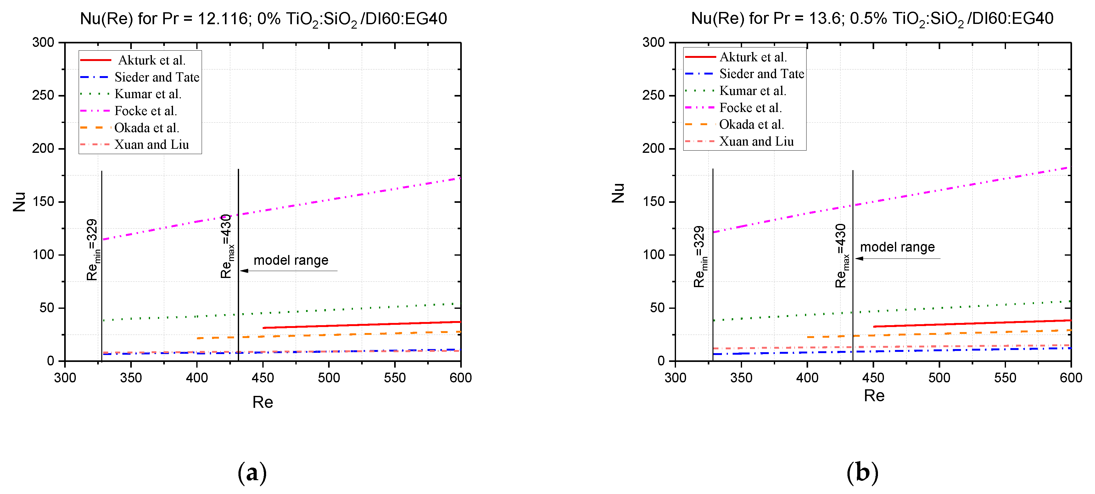
| Model Author | Nusselt Correlation | Reynolds Number Range | HE Type | Remarks |
|---|---|---|---|---|
| Akturk et al. [27] | gasketed-PHE | A = 0.14 m2, β = 30°, u(Nu) = 1.83%, water as operation fluid; 0.57–6.6 m3/h, Th = 53–90 °C, Tc = 9–25 °C; counterflow | ||
| Sieder and Tate [28] | PHE and tube and shell and tube | 0.6 < Pr < 5 | ||
| Re < 2100 | Oil and water as working fluids; for other fluids applicable as well; counterflow Th,c = 71.6–171 °C | |||
| Kumar et al. [29] | PHE, commercial plates | β = 30–60° water, oils | ||
| Focke et al. [30] | 600 < < 16,000 | Models of PHE corrugated field | No data of Pr and mass transfer β = 80°, 70°, 60°, 45°, 30°; γ = 1.0; b = 5.0 mm u(Nu) = 6.5%; u(f) = 3.98% water, air | |
| Okada et al. [31] | 400 < < 15,000 | PHE | β = 15°, 30°, 45°, 60° u(Nu) = 30% |
| Author | Nanoadditive/Base Fluid/Capacity | Nusselt Correlation | Reynolds Range | Remarks |
|---|---|---|---|---|
| Vajjiha et al. [37] | SiO2/60:40 EG:DI, CuO/60:40 EG:DI nanofluids: 0 < f < 0.06%; Al2O3/60:40 EG:DI nanofluid: 0 < f < 0.1 (Al2O3-45 nm, CuO-29 nm, SiO2-20, 50, 100 nm) | 3000 < Re < 6000 | R2 = 0.97 SDmax = 10% u ± 2% | |
| Xuan and Li [38] | Cu/DI nanofluid f < 2% vol. Cu < 100 nm (vol. fraction: 0.3, 0.5, 0.8, 1, 1.2, 1.5, 2%) | 10,000 < Re < 25,000 | u(dNu/Nu) < 4% | |
| Xuan and Li [39] | Cu/DI nanofluid f < 2% vol. Cu < 25 nm (vol. fraction: 0.5, 1, 1.5, 2%) | 200 < Re < 2000 (laminar flow) | ||
| Jafarimoghaddam and Aberoumand [8] | Cu/oil nanofluid (wt. fraction: 0.12, 0.36, 0.72%) | Re < 160 (laminar flow) | u ± 10% | |
| Yashawantha et al. in [35] | Al2O3/65:35 EG:DI (wt. fraction: 0.2–2%) | 100 < Re < 200 (laminar flow); Tnf,in = −5–10 °C, a = 0.287–0.767, b = 5.642–11.09, m = 0.454–0.657, n = 0.909–0.153 | R2 = 0.98 u < 6% |
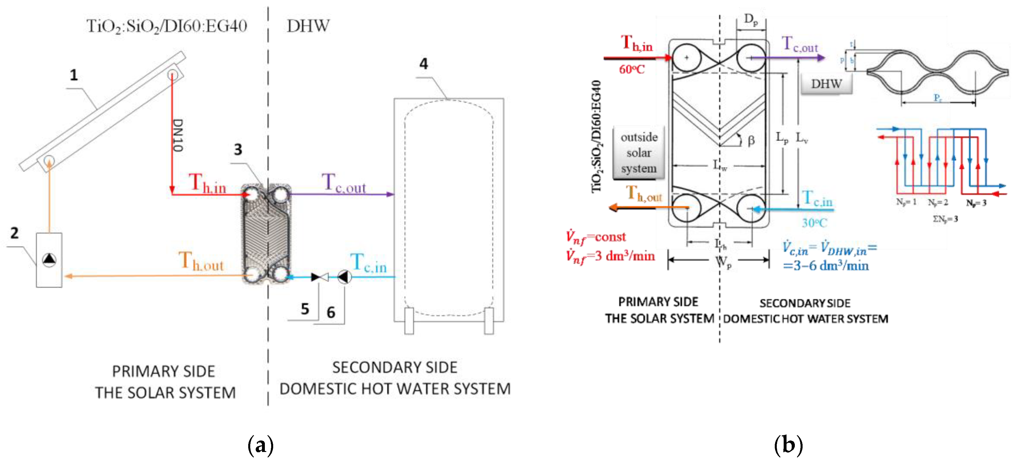
| Technical Parameter of PHE | Symbol | Value |
|---|---|---|
| Plate width between gaskets | Lw, m | 0.18 |
| Plate height between ports | Lv, m | 0.48 |
| Plate height between gaskets | Lp, m | 0.357 |
| Plate width between ports | Lh, m | 0.06 |
| Port diameter | Dp | 30 |
| Chevron angle | β, o | 30 |
| Enhancement factor | ϕ | 1.15 |
| Surface area/heat transfer area | A, m2 | 0.3 |
| Corrugation pitch | Pc, mm | 14.2 |
| Mean channel spacing | b, mm | 2.8 |
| Plate pitch | p, mm | 2.8 |
| Plate thickness | t, mm | 0.45 |
| Total number of plates | 6 | |
| Pass number | 3 | |
| Thermal conductivity | kp, W/mK | 9.5 |
| Working Fluid | 0.5–1.5%Vol. TiO2:SiO2/DI:EG 60:40 | DI:EG 60:40 | DI |
|---|---|---|---|
| Primary Side of PHE | Secondary Side of PHE | ||
| Tin, °C | 60 | 30 | |
| , dm3/min | const = 3 | 3–6 | |
| k, W/mK | 0.468–0.470* ,*2 | 0.449 | 0.6 |
| Pa s | 0.00161–0.00184 *,*3 | 0.00136 | 0.00080 |
| ρ, kg/m3 | 1024.38–1040.38 *,*4 | 1011.87 | 995.77 |
| c, J/kgK | 3956–3877 *,*4 | 3991.00 | 4178.97 |
| Statistical Parameter | TiO2 + SiO2/DI:EG Concentration | |||||
|---|---|---|---|---|---|---|
| Efficiency of PHE, ε | Exergy Efficiency, ηex | |||||
| 0% | 1% | 1.5% | 0.5% | 1% | 1.5% | |
| Residual Sum of Squares | 0.00477 | 0.0043 | 0.00408 | 1.71489 | 1.38782 | 1.03242 |
| Pearson’s r | 0.99851 | 0.99844 | 0.99848 | 0.99603 | 0.99608 | 0.99605 |
| R-Square(COD) | 0.99703 | 0.99688 | 0.99696 | 0.99208 | 0.99217 | 0.99211 |
| Adj. R-Square | 0.99555 | 0.99532 | 0.99544 | 0.98812 | 0.98826 | 0.98816 |
Disclaimer/Publisher’s Note: The statements, opinions and data contained in all publications are solely those of the individual author(s) and contributor(s) and not of MDPI and/or the editor(s). MDPI and/or the editor(s) disclaim responsibility for any injury to people or property resulting from any ideas, methods, instructions or products referred to in the content. |
© 2024 by the author. Licensee MDPI, Basel, Switzerland. This article is an open access article distributed under the terms and conditions of the Creative Commons Attribution (CC BY) license (https://creativecommons.org/licenses/by/4.0/).
Share and Cite
Wciślik, S. The Influence of Nusselt Correlation on Exergy Efficiency of a Plate Heat Exchanger Operating with TiO2:SiO2/EG:DI Hybrid Nanofluid. Inventions 2024, 9, 11. https://doi.org/10.3390/inventions9010011
Wciślik S. The Influence of Nusselt Correlation on Exergy Efficiency of a Plate Heat Exchanger Operating with TiO2:SiO2/EG:DI Hybrid Nanofluid. Inventions. 2024; 9(1):11. https://doi.org/10.3390/inventions9010011
Chicago/Turabian StyleWciślik, Sylwia. 2024. "The Influence of Nusselt Correlation on Exergy Efficiency of a Plate Heat Exchanger Operating with TiO2:SiO2/EG:DI Hybrid Nanofluid" Inventions 9, no. 1: 11. https://doi.org/10.3390/inventions9010011