Article

Asymmetric Method of Heat Transfer Intensification in Radial Channels of Gas Turbine Blades

1
Department of Innovative Technologies of High-Tech Industries, National Research University «Moscow Power Engineering Institute», 111250 Moscow, Russia
2
Department of Thermal Power Plants, National Research University «Moscow Power Engineering Institute», 111250 Moscow, Russia
*
Author to whom correspondence should be addressed.
Inventions 2022, 7(4), 117; https://doi.org/10.3390/inventions7040117
Submission received: 30 July 2022 / Revised: 22 November 2022 / Accepted: 23 November 2022 / Published: 7 December 2022
(This article belongs to the Special Issue Heat transfer and Thermal Managements of Innovative Systems)

Abstract

:
Loop and semi-loop cooling schemes are widely used for the high-temperature gas turbine blades. In such schemes, the mid-chord airfoil parts are traditionally cooled by radial channels with ribbed walls. The blades with a small specific span, or “short” blades, have different heat flux amounts on pressure and suction sides, which results in a temperature difference in these sides of 100–150 °K. This difference causes thermal stresses and reduces the long-term strength margins. This paper presents a new method of heat transfer intensification in the ribbed radial cooling channels. The method is based on air streams’ injection through holes in the ribs that split channels. The streams are directed along the walls into the stagnation zones behind the ribs. The results of a 3D coolant flow simulation with ANSYS CFX code show the influence of the geometry parameters upon the channel heat transfer asymmetry. In the Reynolds number within a range of 6000–20,000, the method provides the heat transfer augmentation difference by up to 40% on the opposite channel walls. Test results presented in the criteria relations form allow for the calculation of mean the heat transfer coefficient along the channel length.

1. Introduction

Gas turbine units of various power classes have found wide application in the energy generation, the oil and gas sector, and a number of other industries [1,2,3]. An essential part of any modern gas turbine is the cooling system [4,5,6]. Traditionally, the following areas of the turbine blade airfoil are distinguished: the leading edge, the middle of the airfoil, and the trailing edge [7,8,9].
A review of the gas turbine blades’ cooling systems shows the frequent use of radial channels, with the heat transfer intensified by ribs. The ribs are installed on both the pressure and suction airfoil sides. Usually, the ribs’ configurations are same, which results in equal coolant side heat transfer coefficients in the considered blade parts. The heat transfer coefficients on the cooling air side are equal; however, the coefficient values on the hot gas side are different. This produces a remarkable temperature difference between the opposite blade sides [10,11].
Design of the blade cooling system must provide the more intensive heat extraction in the heat-loaded areas [12,13]. Some cases need the additional heat transfer intensification on the pressure side and other cases need it on the suction side. The asymmetric heat transfer intensification may keep the wall temperature within the acceptable limits and provides the blade airfoil uniform temperature distribution.
There are a few common factors that have an impact on the level of augmentation when using ribs on the channel walls in the mid-chord region of the blade:
  • Channel shape (aspect ratio, hydraulic diameter);
  • Rib geometry: height, pitch, maximum contact angle, rib alignment, cross-sectional shape of the rib.
The channel shape significantly affects the heat exchange indicators. According to a review, in the case of the rectangular channel geometry, its width W and height H are important. The results of one of the main studies in this area are demonstrated in papers [14,15]. The optimal shape of the channel for different versions of ribs arrangement angles is different. Meanwhile, channels with equal sides (W/H = 1) demonstrate the best characteristics. At the inclination angles of 45° and 60°, the square section channels achieve an augmentation level of 3.5 times at 30° and 2.8 and 2.3 times at 90°, respectively.
The ribs’ pitch impact on the thermal and hydraulic characteristics of the channel depends upon the angle of the ribs’ arrangement, meaning a rib, when positioned at different angles, will have different values of the optimal pitch. The pitch impact is studied in paper [16]. Heat loss in a half-pass channel with the ribs of a different pitch installed at the sidewalls was studied in article [17]. Heat loss parameters were measured for six separate cases by finning pitch ratio. In all design cases, the ribs were located at 90° to the flow.
One disadvantage that occurred during the air flow around the perpendicularly installed ribs of the rectangular shape is the generation of “stagnation zones” behind the rib. Low-intensity reverse flow is generated in the flow separation zone behind the rib-type intensifier, which results in 1.6 times decrease in heat loss coefficient in the “stagnation zone” [18]. The most common for modern cooling system is the use of ribs arranged at different angles. The authors of [19,20] experimentally studied the ribs’ type impact on the density of the heat exchange process in more detail. V-shaped ribs at 60° and 45° ensured the maximum heat loss. Nu/Nu0 for this option was 3 to 3.5; however, V-shaped ribs have the highest hydraulic resistance. The ribs located at 45° also ensure a high intensification with Nu/Nu0 = 2–2.8. This type of rib is characterized by nearly a two-fold lower increase in hydraulic resistance as compared to V-shaped ribs. In [21], continuous parallel V-shaped and Λ-shaped ribs were studied alongside non-continuous ribs of the same types. The studied versions included 90°, parallel ribs; 90°, non-continuous ribs; 60°, non-continuous ribs; 45°, non-continuous ribs; 60°, non-continuous V-shaped ribs; 45°, non-continuous V-shaped ribs; 60°, non-continuous Λ-shaped ribs; 45° non-continuous Λ-shaped ribs; 60°, parallel ribs; 45°, parallel ribs; 60°, V-shaped ribs; 45°, V-shaped ribs. This shows that the use of non-continuous ribs slightly increases hydraulic resistance, and that the highest level of heat exchange intensification is provided by 45° non-continuous V-shaped ribs, Nu/Nu0 = 2.5–3.8. In general, the use of non-continuous ribs in terms of heat exchange process efficiency improvement is preferable to the installation of continuous ribs. However, it is difficult to manufacture such ribbing systems using existing methods. Difficulty in configuring non-continuous ribs may cause multiple defects during their manufacturing. Thus, the most preferable ribbing shape is continuous ribs, located at 45° to the flow, and continuous V-shaped ribs. One of the existing areas of the ribbed channel concept improvement is the generation of complex systems for the improvement of heat exchange characteristics by means of the use of two and more different intensifiers. An example of such combined systems can be the co-use of ribs and slots [22,23]. Paper [23] provides experimental data obtained during thermal tests of parallel ribs, located at 45°, and V-shaped and M-shaped ribs combined with slots. Straight parallel ribs located at 45° combined with slots seem the most efficient. An analysis of the literature dedicated to development and study of the ribbed systems of heat exchange augmentation demonstrates that the authors have mainly solved the task related to the improvement of thermal and hydraulic characteristics of channels with this type of intensifier. Based on the ribbed turbulence promoters in the gas turbines’ blades’ cooling system structure review, the following should be noted: the ribs are installed both on the channel suction and pressure sidewalls. Since the same geometry of ribs is used, therefore, heat loss coefficients are close for both specified airfoil areas. Heat loss coefficient values from the cooling air side differ from heat loss coefficients from the side of hot gases. This results in a significant temperature difference between opposite walls of the channel. The values of the wall temperature of the suction and pressure sides differ significantly. The suction side has lower values of temperature. One of the reasons for the temperature values’ difference on the blade sides is the presence of strong secondary flow, or vortex pair. A vortex pair promotes the gas medium movement from root and perimeter lower temperatures zones to the flow core, thus reducing general thermal stress. To equalize the temperature distribution, radial channels with ribbed turbulence promoters have been designed in such a manner that heat-stressed areas are provided with more intensive heat removal through cooling air. In some cases, an additional augmentation from the pressure side will be required; in other cases, it will be required from the suction side, resulting in the maintenance of the wall temperature within allowable limits and the assurance of an equalized temperature state of the blade airfoil. To that end, heat exchange intensification in the cooling channel shall be asymmetrical. It is suggested to implement the above-mentioned solution by means of the special arrangement of cooling channels with ribbed turbulence promoters.

2. Materials and Methods

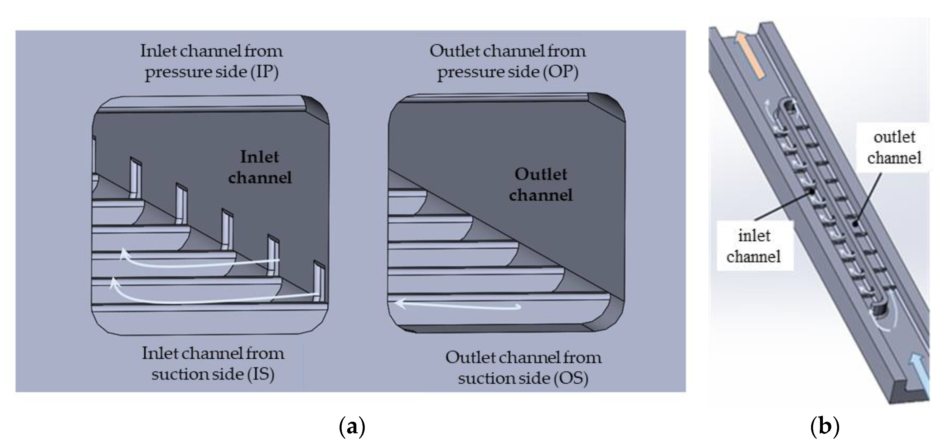
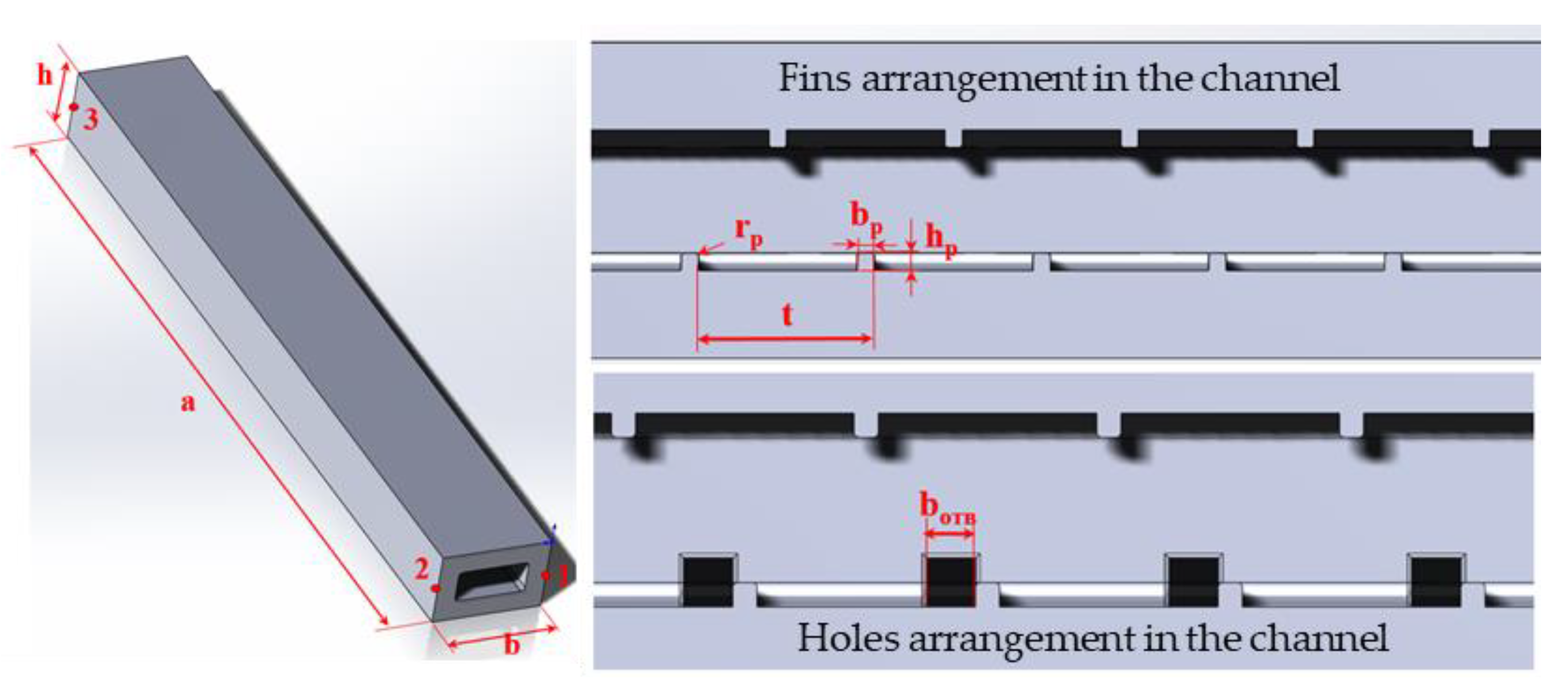
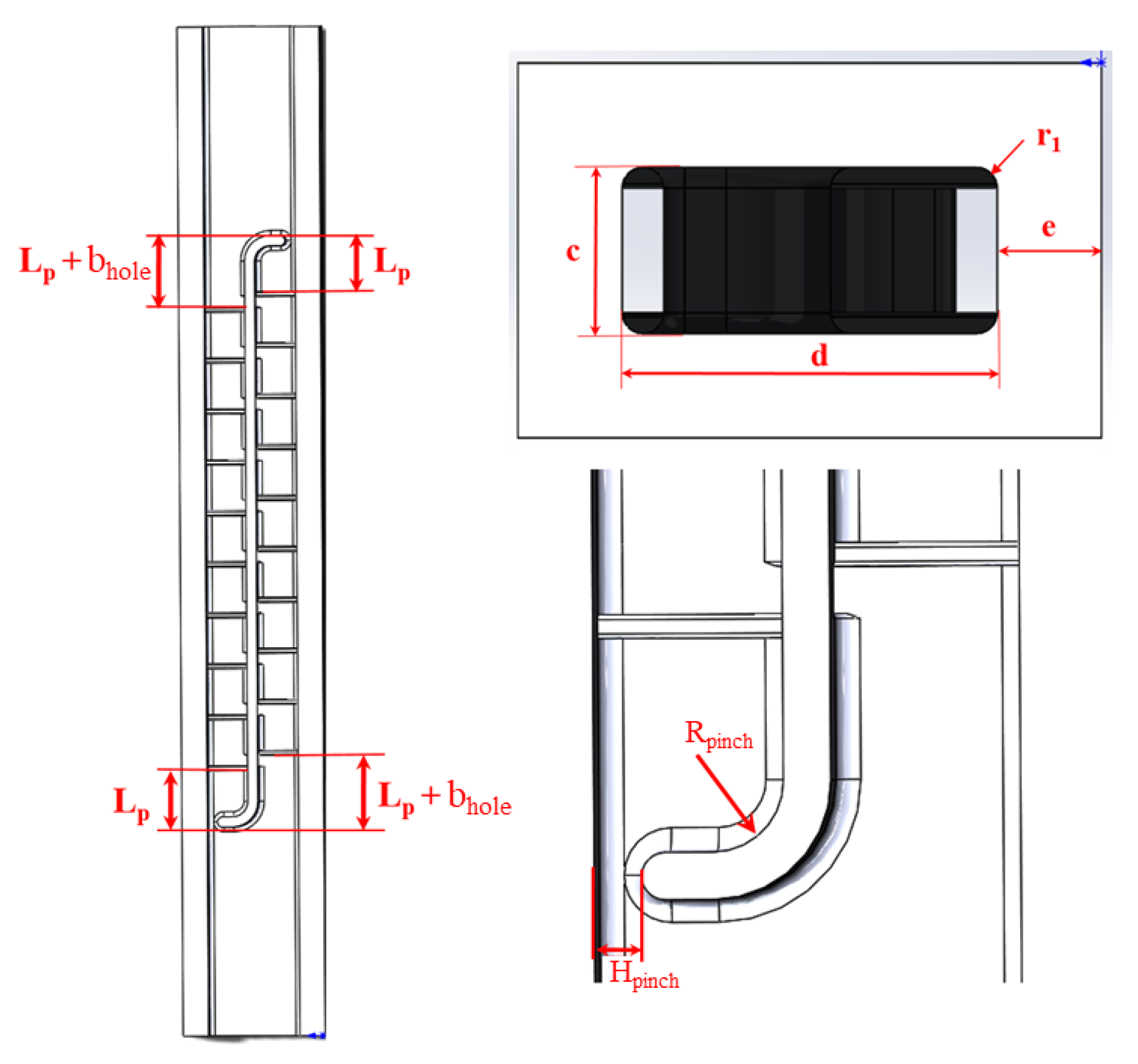
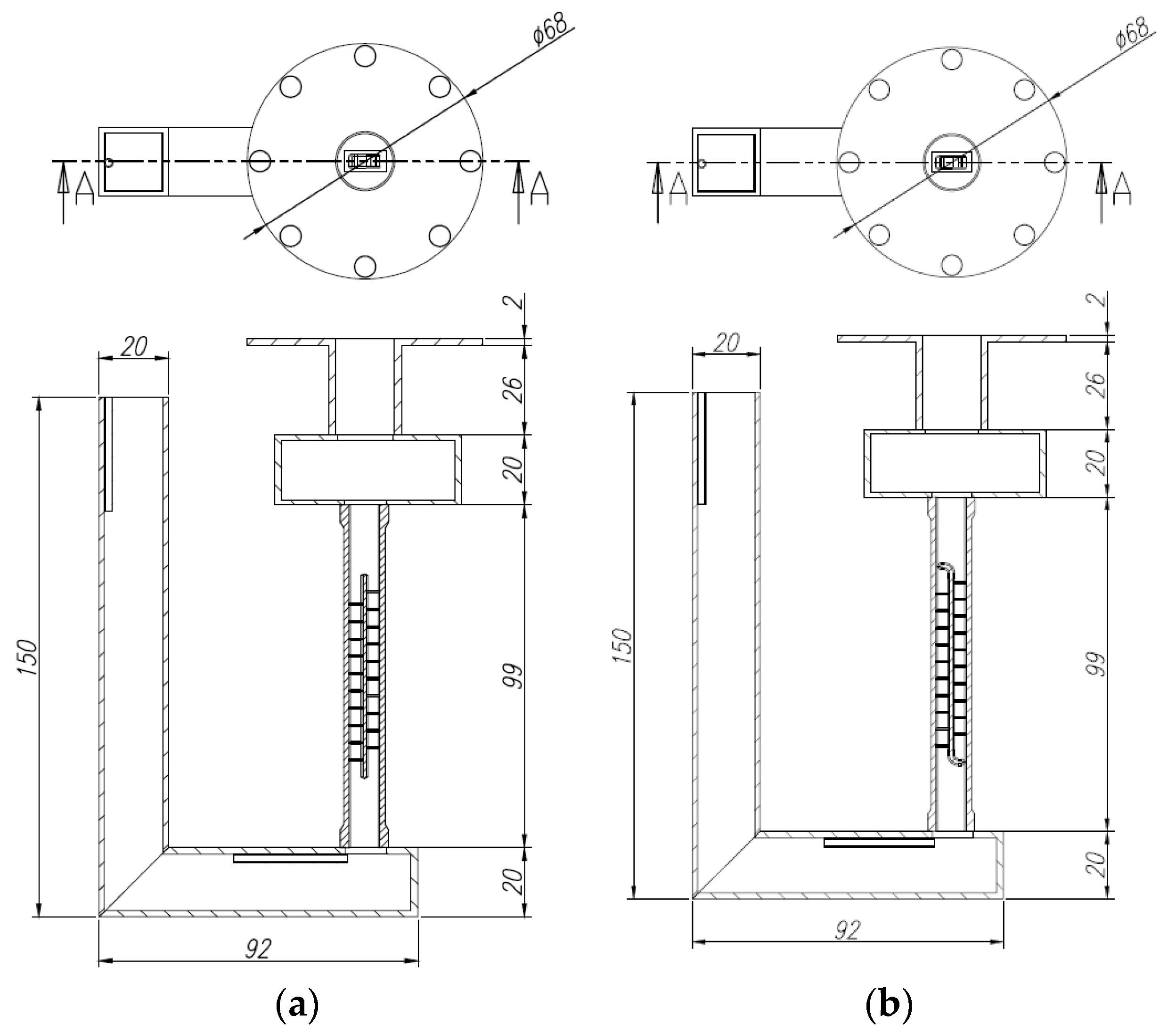
2.1. Research Object

In this article, for 3D modeling of channel models, the SolidWorks 2018 (Dassault Systèmes, Vélizy-Villacoublay, France) software package was used, and ANSYS CFX 18.2 (ANSYS, Inc., Canonsburg, PA, USA) was used for numerical modeling. The continuity equation and steady RANS equations with the k−ω shear stress transport turbulence model are used for CFD calculations implemented in ANSYS CFX.
The research object in this paper is the radial channel of the cooling system that is specific for the mid-chord region of the blade feather midpoint. To increase heat transfer in the channel, the ribs are implemented. The ribs are installed both on the channel suction and pressure sidewalls. To ensure asymmetrical heat removal in channels of the mid-chord region of the blade, it is suggested to arrange blow-off of the boundary layer part from one channel to another through near-the-wall holes (Figure 1). Meanwhile, holes are located near the part of the blade where heat exchange augmentation is required. The studied channel model configuration and dimensions are given in Figure 2 and Figure 3 and Table 1 and Table 2.
The channel from which the cooling agent boundary layer is blown off is called an outlet channel. The channel into which the flow is blown is called an inlet channel. The holes through which a part of the flow is blown off are located upstream of the ribs in the outlet channel and downstream the ribs in the inlet channel. Arrangement of the cooling agent overflow from the outlet channel to the inlet one allows increasing heat removal in both. In the outlet channel, this leads to a reduction in the boundary layer thickness and its thermal resistance. Coolant blowing into the to the rib’s “stagnation” zone of the inlet channel increases effective heat exchange area.

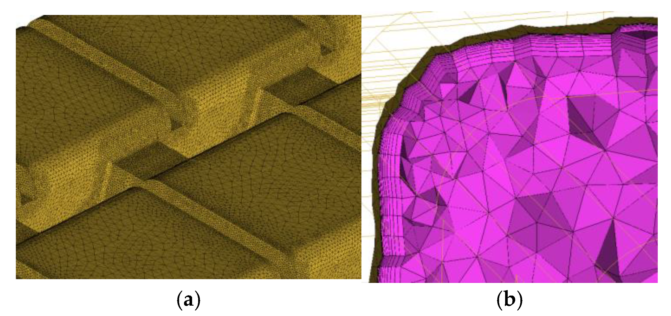
2.2. Numerical Simulation Method

Thermal and hydraulic characteristics of the channel were studied by numerical and experimental methods. Simulation of the processes was performed in Ansys CFX code. The heat transfer problem was solved in a combined approach (conjugate heat transfer) including the cross-influence of the coolant flow and channel wall metal. Solution of the Reynolds-averaged Navier–Stokes equation involved the k–w turbulence model. The finite element modelling model mesh was built in ICEM. The mesh for the metal was non-structured. The element maximal size was 0.5 mm. The minimum size of an element was 0.05 mm. Under such settings, the overall size of meshes was within the range of 6–10 million cells depending on a certain geometry. The mesh had an internal flow volume, non-structured, tetrahedral, with a prismatic layer. Maximum linear size was 0.25 mm. The Minimum linear size of the mesh elements was 0.5 mm. Near-the-wall area had a detailed resolution with the use of prismatic elements having the following parameters: number of prismatic layers—11, initial height of the prism—0.002 mm, growth law–wb-exponential (Figure 4).
During simulation, the following boundary conditions were used:
  • Constant section-averaged static pressure of 1 Bar was established at the model outlet;
  • Mass flow rate of 0.00390743 kg/s and a temperature of 20 °C were established at the inlet;
  • Temperature of the channel external wall Tw was assumed equal to 419 °C, which corresponds to the zinc crystallization temperature on the model external surface. This corresponds to the tests to be carried out on the test rig with the use of a liquid metal thermostat.
The results of the numerical simulation were processed as follows. The ribbed surface of each channel was divided into local areas of equal length; the rounding areas of the channel angles were cut.
After splitting the channel into several surfaces, it is possible to proceed with the determination of the heat transfer coefficient αi, which is determined in accordance with Equation (1).
α i = q i t i _ w t i _ air _ av ,
where qi—a specific heat flow, W/m2; ti_w—a wall temperature from gas side, K; ti_air_av—mean cooling air temperature of K.
Mean temperature of the fluid is calculated from the Equation (2).
t i _ air _ av = t i _ air _ in + t i _ air _ out 2 ,
where ti_air_in, ti_air_out—cooling air temperatures at the model inlet and outlet, K.
Knowing the values of local heat loss coefficients, we can proceed with the determination of the local Nusselt criteria values according to Equation (3) [24,25].
Nu i = α i · d λ i ,
where d—hydraulic diameter, m; λi—thermal conductivity, W/m·K.
The value of thermal conductivity λi is determined as an average value of thermal conductivities determined on surfaces for the collecting channel. This parameter for other channels is determined in the same way.
Hydraulic diameter d is calculated by Equation (4).
d = 4 · S P ,
where S—channel cross-section area, m2; P—channel section perimeter, m.
The parameter of local linear hydraulic resistance fi in a general form can be determined by Equation (5).
f i = Δ P · d 2 · ρ · V 2 · L ,
where ΔP—the pressure drop, Pa; ρ—medium density, kg/m3; V—medium velocity in the channel, m/s; L—channel length, m.
Pressure drop ΔP in the reviewed area is determined as a difference of total pressures determined on surfaces for the collecting channel according to Equation (6).
Δ P i = P 0 _ i in P 0 _ i out ,
Density ρi and velocity vi are determined as an average value of corresponding parameters on the surfaces for the collecting channel. Pressure drop, density, and velocity for other channels are determined in the same way. The length of reviewed linear area L in this case is equal to t.
The Reynolds number is determined using Equation (7).
Re i = G i · d μ i · S ,
where Gi—mean flow rate, m3/s; μi—mean kinematic viscosity, m2/s.
Based on the known Rei number, the local value of Nu0 number is determined by Mikheev’s Equation (8).
Nu 0 = 0.021 · Re 0.8 · Pr 0.43 ,
The Pr criteria value is determined by Equation (9)
Pr = μ i · C p _ i λ i ,
where Cp_i—mean thermal capacity, J/kg.
The values of dynamic viscosity μi and thermal capacity M_i are determined in a manner similar to thermal conductivity λi as an average value between the specified parameters on the inlet and outlet surfaces of the sample volume.
The value of the local linear hydraulic resistance f0 is determined using the Blasius equation (Equation (10)).
f 0 = 0.046 · Re 0.2 .
Then, the local heat exchange augmentation coefficient is determined as Nu/Nu0 ratio. In the same manner, the local relative hydraulic resistance coefficient f/f0 is calculated.
However, information about the level of heat exchange density and the value of hydraulic resistance in some cases is not sufficient to completely assess the prospects of the proposed augmenter’s system. To ensure more comprehensive and unified representation, parameter η is introduced, which is determined by Equation (11).
η = Nu i Nu 0 _ i f i f 0 _ i 1 3 .

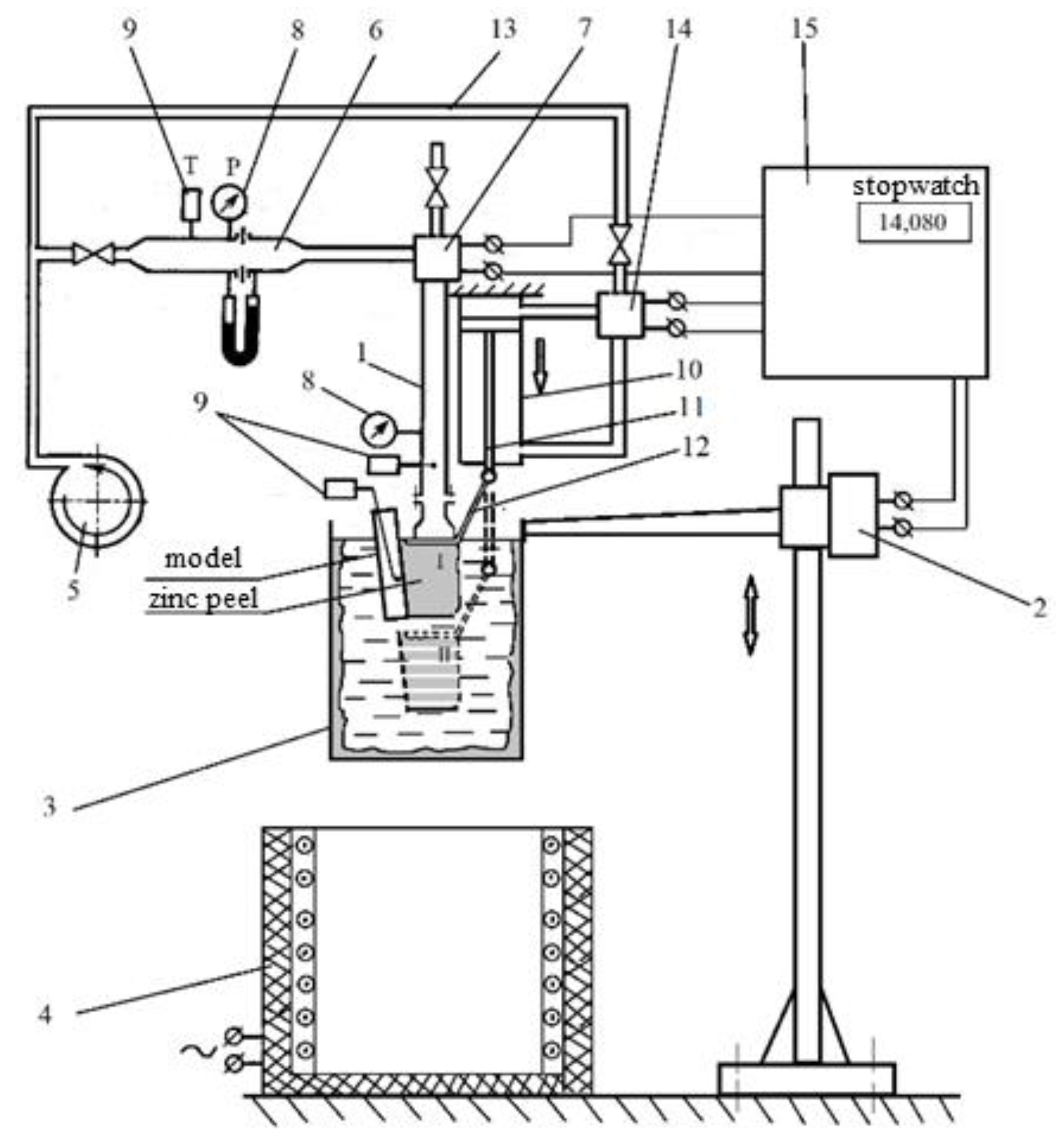
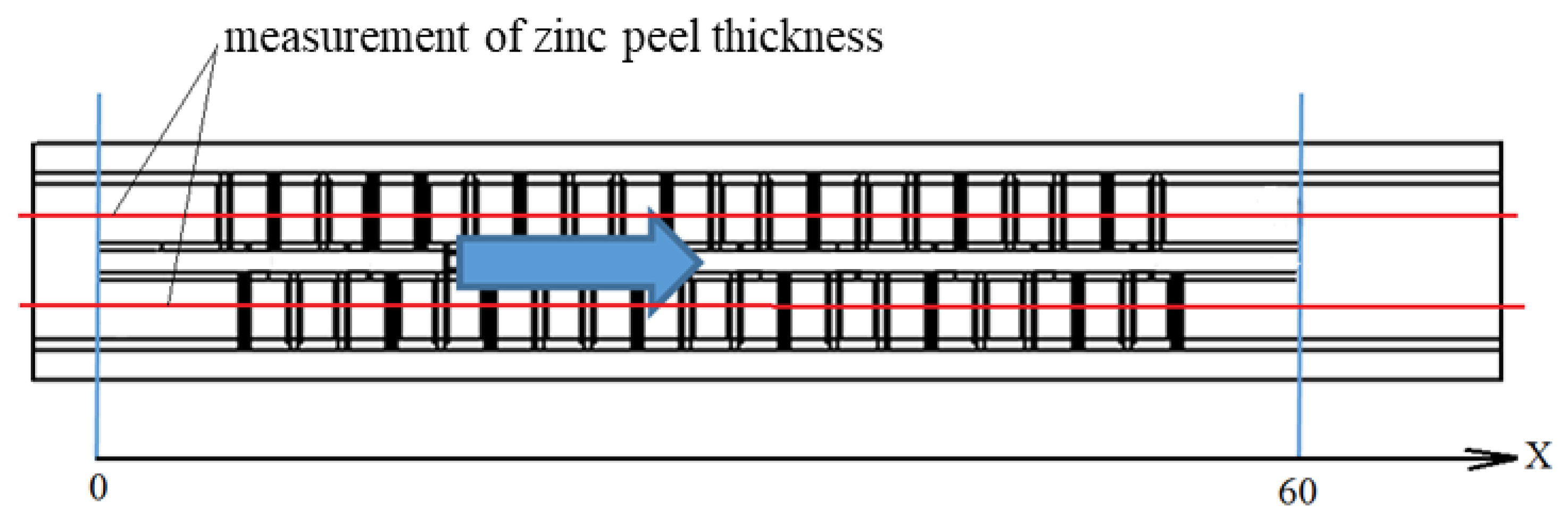
2.3. Experimental Method

The study involved the calorimetry method and use of a liquid metal thermostat (Figure 5).
To carry out physical studies, models of channels were manufactured by selective laser sintering of heat-resistant alloy powder. Simulation of the convectional cooling system for the mid-chord region of the blade was performed in two versions, namely, basic version M1 and the model with asymmetric augmentation system M2 (Figure 6).
Model M1 is a rectangular channel separated by a longitudinal baffle, on the walls of which the ribs are installed to augment heat loss. Model M2 differs with a throat at the discharge channel inlet and a throat at the supply channel outlet generated by the bending of the separating baffle. In addition, the separating baffle has holes which connect two parallel channels. The holes are located by the side of the wall that simulates the pressure side blade wall.
Each obtained zinc skin was checked by the heat balance according to Equation (12). The difference in the heat balance did not exceed 5%.
C p · G air · T air . out T air . in = m · L τ ,
where Cp—air thermal capacity, J/(kg·°C); Gair—cooling air flow rate, kg/s; m—skin weight, kg; L—zinc crystallization heat, J/kg; τ—blowing time, s; Tair.in, Tair.out—measured temperatures at the model inlet and outlet, °C.
Skin thickness was measured with a 3D scanner. The measured thicknesses were averaged by modes; the obtained values were used for calculation of the heat flow density along the external surfaces of the models.
Skin thickness of model M1 was measured in the middle of the parallel channels (Figure 7).
Heat transfer coefficient is determined by Equation (13):
K = δ · ρ · L τ b τ 1 · T cr T air ,
where δ—thickness of the second metal skin generated on the part surface within a period of time (τbτ1) during blowing in crystallizing melt, s; τ1—first skin removal time, s; τb—blowing completion time, s; ρ—density of melted metal, kg/m3Tcr—temperature of melt crystallization, °C; Tair—coolant mean temperature, °C.

3. Results and Discussion

Based on the study results, in the distribution of local heat loss coefficients along the channel’s length from the suction and pressure sides, the value of Nusselt numbers Nu and specific Nusselt numbers were determined.
Nu/Nu0 and f/f0 values averaged by the channel’s length were also calculated, based on which the preliminarily analysis of the results was carried out. Table 3 shows the values K for Reynolds numbers in Re ~20,000 channels.
As shown in Table 3, the most preferable versions are 5–6, which ensure the maintaining of the augmentation level from the suction side and its increase from the pressure side. If the K ratio from the suction and pressure sides (Table 4) is used as part of a criteria, the version can be feasibly used with a large area of holes (versions 2–4 and 8–10).
The augmentation coefficient values depend upon both hole dimensions and the channel’s throat area, which allow changes of cooling density in wide ranges. K variation along the channel’s length also depends upon the Reynolds number, except for the listed structural parameters. Figure 8, Figure 9, Figure 10 and Figure 11 show the variation of the Re number and corresponding K variation in channels of the model, with holes with an area of 1 mm (versions 2–4).
Thus, based on the result of the channel arrangements in the mid-chord region of the blade with asymmetrical flow of the cooling agent, it was established that, to ensure more intensive movement of the cooling agent through by-pass holes, it is required to reduce the open flow area at the collecting channel inlet and at the distribution channel outlet. A reduction in sections results in a larger pressure difference between channels, which ensures the intensive discharge of the boundary layer to the ribs’ stagnation zone and improves heat loss efficiency. The results of the heat exchange simulation in different versions of channels show that the level of heat exchange asymmetry and thermal and hydraulic efficiency of the channels are mostly impacted by the width of the minimum open flow area and the height of a bypass hole. To represent the geometry of the channels, the following parameters were introduced in relative forms: relative section area (the channel minimum to maximum area ratio frel) and relative hole height (hole height to rib height ratio, hrel).
It was established that, when increasing the relative area of the channel square section three times, the heat loss asymmetry coefficient will be reduced by 10–25%, and thermal and hydraulic efficiency will be reduced by 28–33%, depending on the relative height of the bypass hole (Figure 12). The maximum value of the heat loss asymmetry level αAB = 1.4 at the maximum value of thermal, and hydraulic efficiency η = 1.5 is achieved in the relative area of the channel section frel = 0.25; moreover, the relative height of the bypass hole hrel = 2.
To verify the results of a numerical study of the developed method of a convectional cooling arrangement in the channels, experimental studies were carried out with the use of the calorimetry method using a liquid metal thermostat. The basic channel and the channel with asymmetrical heat loss and geometry were studied. The maximum heat loss asymmetry and thermal and hydraulic efficiency are achieved based on the results of numerical simulation. The obtained results of experimental studies (Figure 13) show that the use of the suggested method of asymmetric augmentation ensures an average increase in heat loss of up to 20% from the suction side and 35% from the pressure side.
The obtained experimental results of the channel model with an asymmetrical arrangement of heat removal confirmed the efficiency of the developed method of convectional cooling in the channels of the mid-chord blade region. It has been established that the deviations of the dependence of the Nusselt number upon the Reynolds number, obtained from the simulation results and a physical experiment, are below 6%. Based on the results of numerical and experimental studies, criterial dependencies were created to calculate average heat loss coefficients in the channels with asymmetrical heat exchange augmentation. To calculate the thermal characteristic in the channels of the mid-chord region of the blade from the pressure side, the criterial equation is shown in Equation (14), and Equation (15) shows it from the blade suction side.
Nu = 1.9 · Re 0.44 .
Nu = 1.64 · Re 0.44 .

4. Conclusions

  • The paper discloses the development of the method for asymmetric heat transfer intensification in the radial cooling channels of high-temperature gas turbine blades. The method allows for a reduction in temperature non-uniformity in the mid-chord airfoil part of the blades with loop or semi-loop cooling systems;
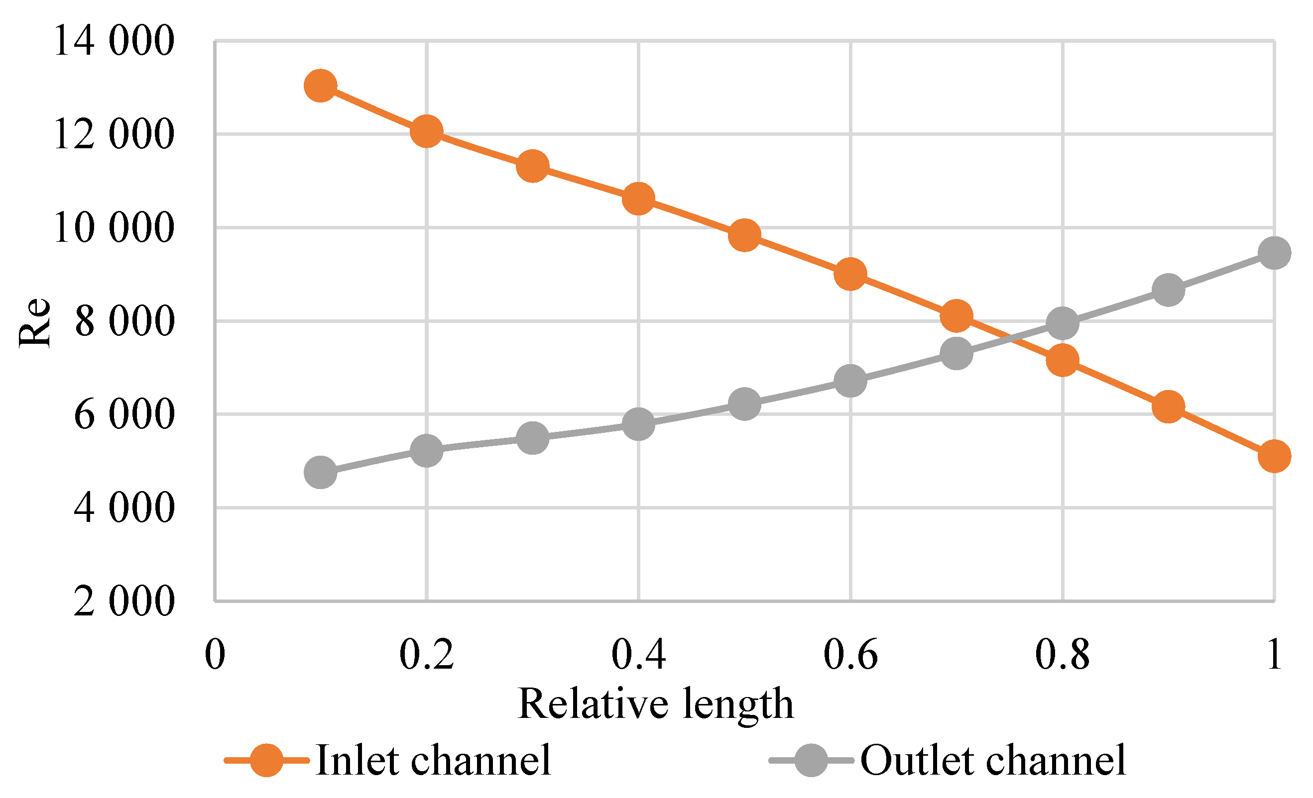
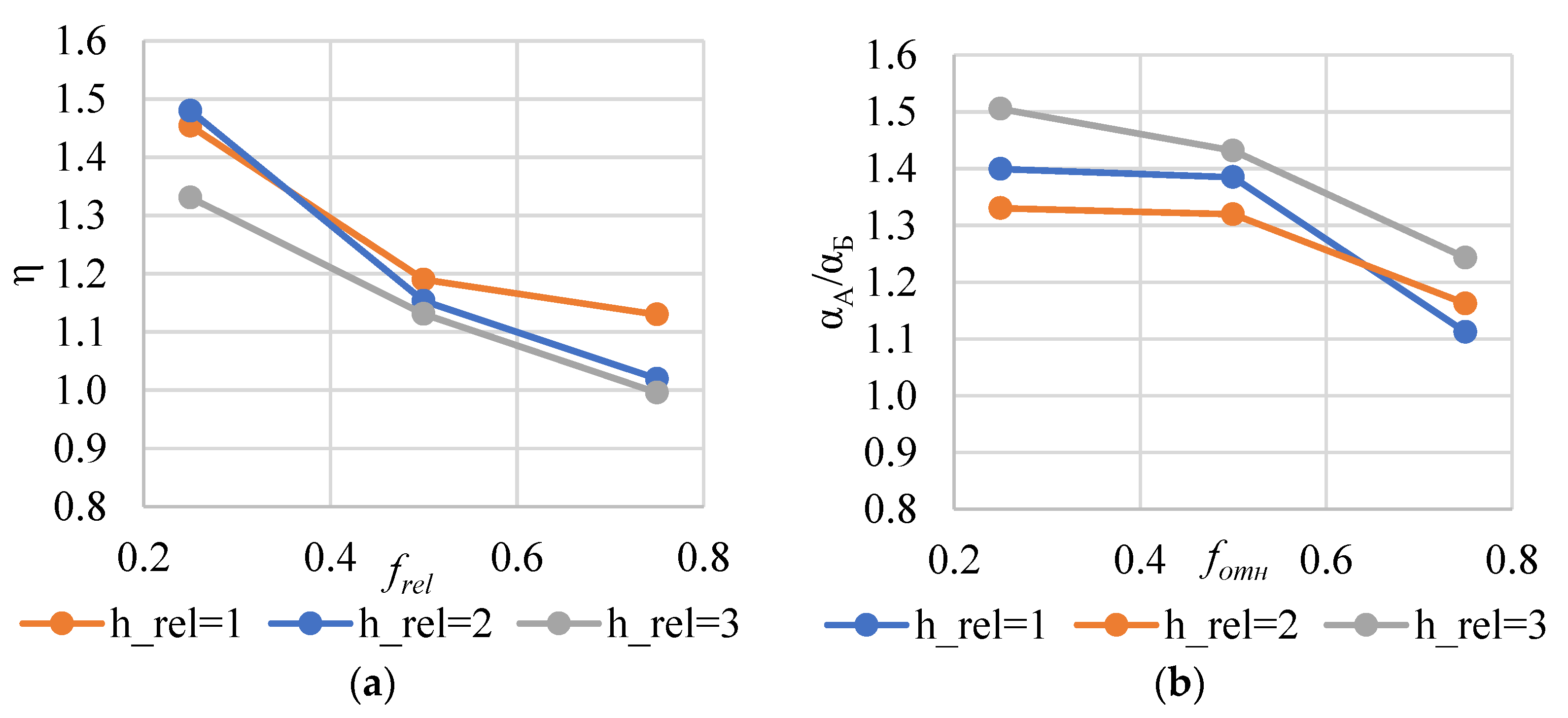
  • In the Reynolds criteria range of 6000–20,000, the asymmetric heat transfer intensification provides a heat flux difference from 15 to 40% on the opposite channel sides;
  • The heat transfer difference on the opposite channel side of 40% and the thermo-hydraulic efficiency reach their maximal values at the channel-specific area of 0.25 and the specific hole diameter in the splitter rib of 2.0;
  • The criteria relations based on the test results allow for the calculation of the mean heat transfer to cooling air along the channel length.

Author Contributions

Conceptualization, S.O. and A.R.; methodology, I.S.; software, A.V.; validation, I.S.; formal analysis, A.R.; investigation, A.V. and N.R.; resources, N.R.; data curation, I.S.; writing—original draft preparation, A.V.; writing—review and editing, N.R.; visualization, S.O.; supervision, S.O.; project administration, N.R.; funding acquisition, A.R. All authors have read and agreed to the published version of the manuscript.

Funding

This study conducted by Moscow Power Engineering Institute was financially supported by the Ministry of Science and Higher Education of the Russian Federation (project No. FSWF-2020–0020).

Institutional Review Board Statement

Not applicable.

Informed Consent Statement

Not applicable.

Data Availability Statement

Not applicable.

Conflicts of Interest

The funders had no role in the design of the study; in the collection, analyses, or interpretation of data; in the writing of the manuscript, or in the decision to publish the results.

References

  1. El-Suleiman, A.; Samuel, O.D.; Amosun, S.T.; Emovon, I.; Ashiedu, F.I.; Fayomi, O.S.I.; Layeni, A.; Nwaokocha, C.N.; Afolalu, S.A. Gas Turbine Performance Forecast and Assessment: GE LM2500 in Outlook. IOP Conf. Ser. Mater. Sci. Eng. 2021, 1107, 012025. [Google Scholar] [CrossRef]
  2. Abam, F.I.; Diemuodeke, O.E.; Ekwe, E.B.; Alghassab, M.; Samuel, O.D.; Khan, Z.A.; Imran, M.; Farooq, M. Exergoeconomic and environmental modeling of integrated polygeneration power plant with Biomass-Based syngas supplemental firing. Energies 2020, 2020, 6018. [Google Scholar] [CrossRef]
  3. Fajardo, J.; Guette, D.; Barreto, D.; Cardona, C.; Baldiris, I. Conventional and advanced exergetic analysis for the combined cycle of power plant with gas turbine of a refinery. IMECE 2021, 85642, V08BT08A011. [Google Scholar]
  4. Qian, X.; Yan, P.; Wang, X.; Han, W. Numerical Analysis of Conjugated Heat Transfer and Thermal Stress Distributions in a High-Temperature Ni-Based Superalloy Turbine Rotor Blade. Energies 2022, 15, 4972. [Google Scholar] [CrossRef]
  5. Laveneziana, L.; Rosafio, N.; Salvadori, S.; Misul, D.A.; Baratta, M.; Forno, L.; Valsania, M.; Toppino, M. Conjugate Heat Transfer Analysis of the Aero-Thermal Impact of Different Feeding Geometries for Internal Cooling in Lifetime Extension Processes for Heavy-Duty Gas Turbines. Energies 2022, 15, 3022. [Google Scholar] [CrossRef]
  6. Kindra, V.O.; Rogalev, A.N.; Osipov, S.K.; Zlyvko, O.V.; Vegera, A.N. Numerical study of flow and heat transfer in a rectangular channel with pin fin arrays and back ribs. In Proceedings of the 14th European Conference on Turbomachinery Fluid dynamics & Thermodynamics, Gdansk, Poland, 12–16 April 2021. [Google Scholar]
  7. Wu, W.; Yao, R.; Wang, J.; Su, H.; Wu, X. Leading edge impingement cooling analysis with separators of a real gas turbine blade. Appl. Therm. Eng. 2022, 208, 118275. [Google Scholar] [CrossRef]
  8. Ma, Y.; Fan, X.; Huai, X.; Cheng, K. Numerical investigation on multi-stage swirl cooling at mid-chord region of gas turbine blades. Appl. Therm. Eng. 2022, 216, 119003. [Google Scholar] [CrossRef]
  9. Liang, C.; Rao, Y.; Luo, J.; Luo, X. Experimental and numerical study of turbulent flow and heat transfer in a wedge-Shaped Channel with guiding pin fins for turbine blade trailing edge cooling. Int. J. Heat Mass Transf. 2021, 178, 121590. [Google Scholar] [CrossRef]
  10. Dinh, C.T.; Nguyen, T.M.; Vu, T.D.; Park, S.G.; Nguyen, Q.H. Numerical investigation of truncated-root rib on heat transfer performance of internal cooling turbine blades. Phys. Fluids 2021, 33, 076104. [Google Scholar] [CrossRef]
  11. Sreekesh, K.; Tafti, D.K.; Vengadesan, S. The combined effect of coriolis and centrifugal buoyancy forces on internal cooling of turbine blades with modified ribs using Large Eddy Simulation (LES). Int. J. Therm. Sci. 2022, 182, 107797. [Google Scholar] [CrossRef]
  12. Nourin, F.N.; Amano, R.S. Review of gas turbine internal cooling improvement technology. J. Energy Resour. Technol. 2021, 143, 080801-1. [Google Scholar] [CrossRef]
  13. Unnikrishnan, U.; Yang, V. A review of cooling technologies for high temperature rotating components in gas turbine. Propuls. Power Res. 2022, 11, 293–310. [Google Scholar] [CrossRef]
  14. Liu, Z.; Feng, Z. Numerical simulation on the effect of jet nozzle position on impingement cooling of gas turbine blade leading edge. Int. J. Heat Mass Transf. 2011, 5423, 4949–4959. [Google Scholar] [CrossRef]
  15. Han, J.C.; Dutta, S.; Ekkad, S. Gas Turbine Heat Transfer and Cooling Technology; CRC Press: Boca Raton, FL, USA, 2012; p. 871. [Google Scholar]
  16. Han, J.C.; Park, J.S. Developing heat transfer in rectangular channels with rib turbulators. Int. J. Heat Mass Transf. 1988, 31, 183–195. [Google Scholar] [CrossRef]
  17. Han, J.C.; Ou, S.; Park, J.S.; Lei, C.K. Augmented heat transfer in rectangular channels of narrow aspect ratios with rib turbulators. Int. J. Heat Mass Transf. 1989, 32, 1619–1630. [Google Scholar] [CrossRef]
  18. Leontiev, A.I.; Olimpiev, V.V. Thermal Physics and Heating Engineering of Advanced Heat Exchange Augmentors (Review). Power Eng. 2011, 1, 7–31. [Google Scholar]
  19. Xu, G.; Li, Y.; Deng, H. Effect of rib spacing on heat transfer and friction in a rotating two-pass square channel with asymmetrical 90-deg rib turbulators. Appl. Therm. Eng. 2015, 80, 386–395. [Google Scholar] [CrossRef]
  20. Han, J.C.; Zhang, Y.M.; Lee, C.P. Augmented heat transfer in square channels with parallel, crossed, and V-shaped angled ribs. J. Heat Transfer. 1991, 113, 590–596. [Google Scholar] [CrossRef]
  21. Zhao, J.; Huang, S.; Gong, L.; Huand, Z. Numerical study and optimizing on micro square pin-rib heat sink for electronic cooling. Appl. Therm. Eng. 2016, 93, 1347–1359. [Google Scholar] [CrossRef]
  22. Han, J.C.; Zhang, Y.M. High performance heat transfer ducts with parallel broken and V-shaped broken ribs. Int. J. Heat Mass Transf. 1992, 35, 513–523. [Google Scholar] [CrossRef]
  23. Singh, P.; Pandit, J.; Ekkad, S.V. Characterization of heat transfer enhancement and frictional losses in a two-pass square duct featuring unique combinations of rib turbulators and cylindrical dimples. Int. J. Heat Mass Transf. 2017, 106, 629–647. [Google Scholar] [CrossRef]
  24. Afzal, A.; Islam, M.; Kaladgi, A.R.; Manokar, A.M.; Samuel, O.D.; Mujtaba, M.A.; Soudagar, M.E.M.; Fayaz, H.; Ali, H.M. Experimental investigation on the thermal performance of inserted helical tube three-fluid heat exchanger using graphene/water nanofluid. J. Therm. Anal. Calorim. 2022, 147, 5087–5100. [Google Scholar] [CrossRef]
  25. Setiyo, M.; Purnomo, B.C.; Waluyo, B.; Munahar, S.; Rochman, M.L.; Saleh, A.R.; Fatmaryanti, S.D.; Samuel, O.D. Cooling power characteristics of half-cycle refrigeration system in LPG fuelled vehicles by auxiliary chiller as heat exchanger. Therm. Sci. Eng. Prog. 2022, 27, 101145. [Google Scholar] [CrossRef]
Figure 1. Design of channel with asymmetrical flow of the cooling agent in channels: (a) front view; (b) isometric view.
Inventions 07 00117 g001
Figure 2. General view of the channel and augmenters arrangement.
Inventions 07 00117 g002
Figure 3. Geometric parameters of aerodynamic pinch.
Inventions 07 00117 g003
Figure 4. Computational grid: (a) in the proximity of holes; (b) cross-section.
Inventions 07 00117 g004
Figure 5. Experimental rig for studying channels: 1—operating area; 2—hoisting device; 3—melted zinc; 4—muffle furnace; 5—compressor; 6—flow meter; 7—electro-pneumatic valve; 8—pressure gauge; 9—thermocouple; 10—pneumatic cylinder; 11—stem; 12—zinc peel; 13—air line; 14—electro-pneumatic valve; 15—control unit.
Inventions 07 00117 g005
Figure 6. Versions of the convectional cooling system model: (a) model M1; (b) model M2.
Inventions 07 00117 g006
Figure 7. Schematic set-up of the reference sections in which heat flow density is shown.
Inventions 07 00117 g007
Figure 8. Distribution of Reynolds numbers lengthwise of the channels, case 2.
Inventions 07 00117 g008
Figure 9. Distribution of K values lengthwise of the channels, case 2.
Inventions 07 00117 g009
Figure 10. Distribution of Re numbers lengthwise of the channels, case 4.
Inventions 07 00117 g010
Figure 11. Distribution of K values lengthwise of the channels.
Inventions 07 00117 g011
Figure 12. Results of numerical simulation in different versions of channels with asymmetric heat exchange augmentation: (a) thermal and hydraulic efficiency; (b) heat loss asymmetry coefficient.
Inventions 07 00117 g012
Figure 13. Test results on Nusselt numbers vs. Reynolds numbers.
Inventions 07 00117 g013
Table 1. Dimensions of studied models.
DesignationDefinitionValue
aModel length99 mm
bModel width14 mm
hModel height9 mm, 7 mm
cInlet channel height4 mm, 2 mm
dInlet section channel width9 mm
dкChannel width in the area of intensification4 mm
eWall thickness2.5 mm
r1Corner radius for channel walls0.5 mm
tRib installation step5 mm
bpRib width0.5 mm
hpRib height0.5 mm
rpRib chamfer radius0.1 mm
bholeHole sizevar
RpinchRadius of a quarter circle forming an aerodynamic kink1.5 mm
HpinchThe size of the throat section at the inlet and outlet to the channels in the pinch area4 mm, 3 mm, 2 mm, 1 mm
LpDistance from the beginning of the baffle to the first/last rib5.5 mm
Table 2. Dimensions of models.
VersionHole Size
mm
Hole Area
mm2
Throat Size
mm
Throat Area
mm2
Case 100416
Case 21114
Case 31128
Case 411312
Case 50.50.514
Case 60.50.528
Case 70.50.5312
Case 81.51.514
Case 91.51.528
Case 101.51.5312
Table 3. Models for the thermal and hydraulic parameters investigated.
K = Nu/Nu0f/f0
VersionInlet Pressure (IP)Inlet Suction (IS)Outlet Pressure (OP)Outlet Suction (OS)Inlet Pressure (IP)Inlet Suction (IS)Outlet Pressure (OP)Outlet Suction (OS)
Case 11.951.951.951.957.037.968.007.84
Case 22.251.804.463.204.826.167.9511.70
Case 31.931.643.372.294.735.809.539.88
Case 41.751.592.312.064.675.697.157.93
Case 52.221.943.993.094.567.148.328.32
Case 62.011.842.902.274.757.237.697.95
Case 72.192.052.572.206.228.647.628.40
Case 82.311.803.832.686.718.6812.0013.14
Case 92.021.653.182.245.746.989.069.83
Case 101.851.602.441.945.697.057.618.39
Table 4. Asymmetrical heat transfer rates.
VersionKIP/KISKOP/KOS
Case 21.251.40
Case 31.181.47
Case 41.101.12
Case 51.151.29
Case 61.091.28
Case 71.071.17
Case 81.281.43
Case 91.221.42
Case 101.161.26
Publisher’s Note: MDPI stays neutral with regard to jurisdictional claims in published maps and institutional affiliations.

