Article

Development of Solutions for Increasing the Combustion Efficiency of Hydrogen in Water Vapor in a Hydrogen-Oxygen Steam Superheater

1
Department of Innovative Technologies of High-Tech Industries, National Research University “Moscow Power Engineering Institute”, 111250 Moscow, Russia
2
Department of Thermal Power Plants, National Research University “Moscow Power Engineering Institute”, 111250 Moscow, Russia
*
Author to whom correspondence should be addressed.
Inventions 2023, 8(1), 6; https://doi.org/10.3390/inventions8010006
Submission received: 15 November 2022 / Revised: 19 December 2022 / Accepted: 23 December 2022 / Published: 27 December 2022
(This article belongs to the Special Issue Heat transfer and Thermal Managements of Innovative Systems)

Abstract

:
The study is aimed at revealing the specific features of the burning of hydrogen with oxygen in a water-vapor atmosphere. The purpose of the study is to define the optimal values for diluting the burning mixture with water vapor in the active burnout zone, providing the minimal values of incomplete combustion. Modeling of burning processes was carried out with the use of kinetic mechanisms in the Ansys Chemkin-Pro software. The result of the study was the definition of critical water vapor content in a burning mixture as 60% fraction of total mass with, obtaining dependencies of key parameters of the burning process within a wide range. The mechanism of chemical kinetics was selected for further modeling in a three-dimensional setting, and tasks for the formulation of requirements and methods for the design of efficient hydrogen combustion chambers were set up for 500 MW gas turbine plants at a supercritical pressure of 20 MPa or higher.

1. Introduction

In compliance with the Energy Strategy of the Russian Federation for the period until 2035 [1] and the Paris Agreement within the United Nations Framework Convention on Climate Change [2], the reduction of emissions of carbon dioxide is necessary. One of the ways to achieve this global target is to replace the carbon-containing types of fuel with totally or partially carbon-free types. Hydrogen, which has a lower specific heat of combustion at 120 MJ/kg, was selected as the most promising fuel based on the amount of heat generated during combustion.
The supercritical regime is characterized by high temperatures and pressures, which affect the flow behavior [3]. When the supercritical parameters are reached, the surface tension decreases, the constant-pressure specific heat increases, and the density approaches the values for a liquid under normal conditions [4,5].
Table 1 compares the main thermophysical parameters of steam at temperatures equal to 813 K and 1173 K at supercritical parameters, subcritical parameters, and with water at normal pressure, obtained using the NIST REFPROP database [6]. The results of the comparison show that when operating in a supercritical mode, the parameters of a gas affecting mixing change significantly. For a correct study, this fact must be taken into account in the methods used for studying approximate correlations.
One of the methods to intensify the combustion process and increase the efficiency of combustion is to increase the temperature in the active oxidizing zone in order to increase the particle evaporation rate. The aspects of hydrogen burning in a water-vapor atmosphere have been studied in the work of Borzenko V. et al. [7], who obtained results on the dependence of superheated steam and the efficiency of fuel combustion on the fraction of total weight of water vapor and the oxidizer excess factor.
Komarov I. et al. [8] have carried out a similar study for the burning of methane in a CO 2 diluter medium, using the Chemkin computer simulation code, and have assessed the influence of the CO 2 fraction from 60 to 79% on the burning process at an oxidizer excess coefficient of 0.7 to 1.4. Rogalev A. et al. [9] reached a conclusion on the considerable slowing of the burning process with increasing dilution degree as well as the definition of threshold dilution degree and velocities of gas-fuel mixture for prevention of decay.
Water vapor, in turn, also works as an inhibitor of the burning process, and its mass content in the mix is significant. The conditions of hydrogen burning in a water vapor atmosphere are considerably different from the operating conditions of conventional gas turbine plants (GTP). When the burning mixture is diluted with water vapor, it may possibly decay due to flameout at a low flame propagation rate or stop burning due to insufficient heating temperatures of the fuel and oxidizer.
The authors of [10,11,12,13,14] deal with studies of the burning process, the definition of kinetic mechanisms [7], and the quantitative determination of combustion discharge parameters.
Burning in a hydrogen-oxygen steam superheater (HOSS)-combustion chamber (HOCC) involves going into an atmosphere of water vapor subjected to heating. A mixture of oxygen and water vapor in various proportions is supplied to the mixing zone as an oxidizer, and hydrogen is the fuel. On exit from the mixing element, hydrogen is completely mixed with the oxidizer and then ignited by an electric plug. The remaining vapor is supplied to the mixing zone to be mixed with combustion discharge.
This study is dedicated to the assessment of the most important parameters of the working burning process under critical conditions in the hydrogen-oxygen combustion chamber (HOSS) at high pressure, namely a normal flame propagation rate of U n m/s, an adiabatic flame temperature discharge of T a d , K, and efficiency of fuel combustion η c .

2. Research Objects and Methods

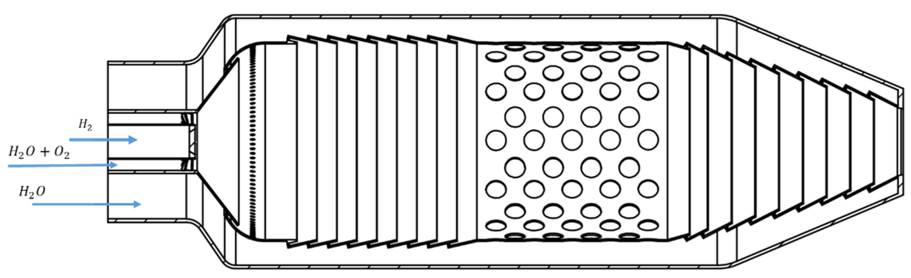
2.1. A Hydrogen-Oxygen Combustion Chamber

The development of solutions to improve the efficiency of hydrogen combustion was carried out for an external hydrogen–oxygen combustion chamber (HCC). HCC is used in the diagram as a power unit operating on high steam parameters. When burning hydrogen, the majority of the steam is sent after the boiler to overheat. The heat flow diagram is shown in Figure 1.
The initial data for the design of the external combustion chamber due to the operation of the power unit equipment are shown in Table 2.
Steam with a pressure of 23.5 MPa and a temperature of 813 K is supplied from the boiler to a hydrogen-oxygen steam superheater (HOSS) to be heated to a higher temperature. The introduction of HOSS into the plant allows for a reduced consumption of carbon-containing fuel needed for steam superheating.
During the analysis of designs for hydrogen-oxygen steam superheaters [15,16,17,18,19,20,21], a straight-flow combustion chamber of an energy plant [12] was selected as a prototype in Figure 2.
Adjustment of temperature and flame propagation rate is carried out by changing the fraction of water vapor γ, Equation (1), within a wide range [7].
γ = m ˙ H 2 O m ˙ s m ,
where m ˙ H 2 O —mass consumption of water vapor supplied to the active burnout zone, kg/s; m ˙ s m —mass summary consumption of fuel and water vapor components, kg/s.

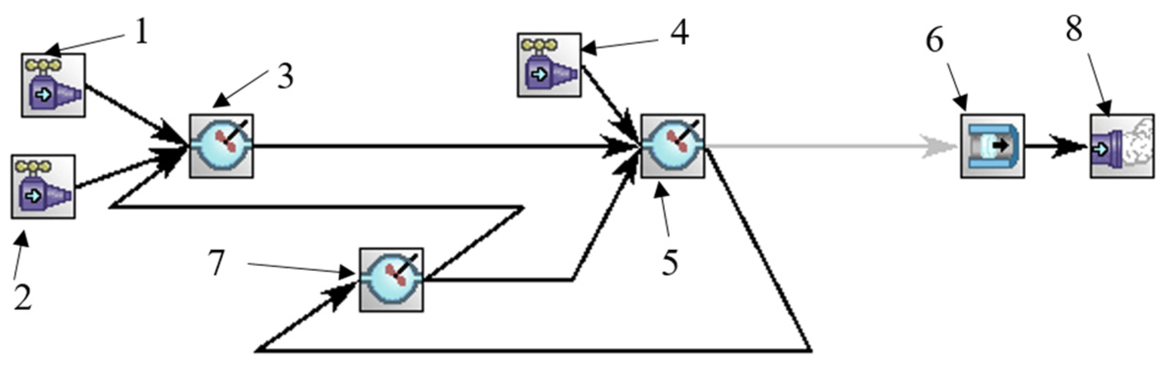
2.2. Analysis Method for the Hydrogen-Oxygen Combustion Chamber

A parametric study of burning under supercritical parameters, a pressure above 200 bar, and the influence of the degree of dilution of oxidizer by water vapor, was carried out with the use of Ansys Chemkin-Pro [22] program code.
Modeling of the processes of burning kinetics was carried out with the use of USC II [23]; a detailed kinetic mechanism. This mechanism is designed to represent different combustion scenarios. USC II comprises 111 species and 784 reactions, and it is used in the studies by the authors of [24,25,26]. The USC II mechanism used has been previously used to study combustion processes at supercritical parameters of methane with oxygen in a carbon dioxide environment, considering the oxidation reactions of CO and H 2 [27]. The mechanisms use approximating thermophysical properties for the supercritical regime.
The calculation of the adiabatic temperature of combustion discharge was carried out using the equilirial parameters of the ideal gas model without any account for the influence of thermodynamic parameters upon the mixing process. The temperature and pressure of the mixture were defined by component parameters and their proportions in the mix. The mass fractions of the mixture’s components were used to define the mixture for the study of the chemical kinetics of burning.
The reactor diagrams were developed, comprising elementary models for the calculation of adiabatic temperature T a d in an equilibrial reactor and a normal rate of flame propagation U n with the use of a flame propagation rate counter.
In order to define the efficiency of organizing the hydrogen burning process, an analysis of a mole fraction of unburned hydrogen after the flameout zone is undertaken, applying the earlier received parameters from the Ansys Chemkin Pro software.
A standard, calculated design of the combustion chamber of a gas turbine engine was taken as the basis for the arrangement as shown in Figure 3. The combustion chamber model was built using the Chemkin-Pro software package and consists of two groups of reactors. The first group of reactors simulates the area around the flame, and the second group simulates the afterburning area between the burning zone and the turbine inlet. An ideal mixing reactor was chosen to simulate the mixing zone since the fuel in this zone is partially mixed with the oxidizer.
Basic data for studying HOSS are represented in Table 3.
The calculation of the burning mixture temperature T m i x [K] was carried out according to Equation (2):
T m i x = m ˙ H 2 T H 2 C p H 2 + m ˙ O 2 T O 2 C p O 2 + m ˙ H 2 O T H 2 O C p H 2 O m ˙ H 2 C p H 2 + m ˙ O 2 C p O 2 + m ˙ H 2 O C p H 2 O ,
where m ˙ H 2 ,   m ˙ H 2 O ,     and   m ˙ O 2 and—mass consumption of hydrogen, water vapor, and oxygen accordingly, kg/s;
T H 2 ,   T H 2 O ,   and     T O 2 —temperature of hydrogen, water vapor, and oxygen accordingly, K;
c p H 2 ,   c p H 2 O ,     and   c p O 2 —specific heat capacity of hydrogen, water vapor, and oxygen accordingly, kg/s.
The mixture pressure was calculated through the partial pressures of the components in Equation (3):
p m x = P i = p i · x i ,
where P i —the partial pressure of the i-th component;
p i —pressure of the i-th component;
x i —mole fraction of the i-th component in the mix.
Table 4 lists the parameters for a mixture of oxidizers and the results of the calculation of the mole fraction of unburnt hydrogen, x H 2 n b .
The time of presence in the mixing zone is 0.0005 s; in the burnout and recirculation zone, 0.002 s. The burning process for γ above 0.6 failed due to a shorter presence time.
Equation (4) allows for the completeness of combustion by defining the number of moles n H 2 n b of unburned hydrogen in the mixture of combustion discharge products.
n H 2 n b = x H 2 n b · n ,
where n = n H 2 + n H 2 O + n O 2 ;
n —summary number of mole components in the mix;
n H 2 , n H 2 O , n O 2 —number of moles of hydrogen, water vapor, and oxygen accordingly;
n H 2 n b —number of moles of unburnt hydrogen in the outlet section of the chamber.
The fuel combustion efficiency of η b is determined in Equation (5):
η b = n H 2 n H 2 n b n H 2 · 100 % .

3. Results and Discussion

The parameters of combustion discharge products T a d and U n were defined for the range γ from 0 to 0.8 in 0.1 increments and an equivalence ratio from 0.8 to 1.2.
The change in the adiabatic temperature of combustion discharge products with the ideal gas model is represented in Figure 4.
The highest level of adiabatic temperature is reached at the stoichiometric ratio, and further results of defining the normal rate of distribution are shown for a specified degree of oxidizer factor.
A reduction in temperature with the increased share of ballast components in the mix seems explainable from a physical point of view.
A dilution degree working range is defined by taking into account the limitation of combustion products on one side and the maximum permissible hot gas temperature on the inner wall of the combustion chamber on the other, as well as a self-ignition temperature for sustainable burning. A limiting factor in the development of a burning process shall be the flame propagation rate U n above the rate-limiting flame propagation rate U l i m of 70 cm/s to provide for stable propagation of a flame front along the length of the combustion chamber.
The results of the definition of a normal flame propagation rate are presented in Figure 5.
Taking into account all the requirements for organizing a working process of burning in the superheater, the maximum dilution degree is 0.6.
The obtained data on the completeness of combustion are reflected in Table 5 and derive a dependence of combustion efficiency η b on the degree of mixture dilution with water vapor γ in Figure 6.
Among the obtained results, the highest values of the target parameters are achieved with an oxidizer excess dilution factor of one and a maximum dilution degree when γ m a x is 0.6. At this dilution degree, the adiabatic temperature in the burnout zone is close to values typical for combustion chambers in GTP and GDT. It will be accepted for further studies of the burning process in a three-dimensional setting to define the influence of geometrical and thermo-dynamical factors and for the development of measures on the design of structures and layouts of hydrogen-oxygen combustion chambers.
When analyzing Figure 3, Figure 4 and Figure 5, a number of conclusions are formed explaining the dependence of the completeness of combustion on the degree of dilution of the mixture at the time of its arrival in the zones of recirculation, afterburning, and flame zone. The residence time of the component τ r e s is 0.0025 s.
As a result of a decrease in the adiabatic temperature in the flame zone and a change in the heat capacity and the diffusion coefficient of the mixture, the rate of oxidation of the fuel and combustion decreases.
A decrease in the rate affects the time of the limiting reactions, thereby reducing the completeness of hydrogen combustion with an increase in the degree of dilution of the mixture with water vapor.

4. Conclusions

The results of the study of hydrogen burning in a water vapor atmosphere reveal a high influence of the degree of diluting the burning mix and define a quantitative assessment in the operation of HOSS with up to 1 MW of power.
In the result of the study of the burning process under a critical pressure value of 23.5 MPa, dependencies were defined for adiabatic temperature, normal flame propagation rate, and fuel combustion efficiency relative to the degree of diluting the active burnout zone with water vapor.
The organization of stable and efficient combustion of hydrogen at high pressure is possible, taking into account the following conditions:
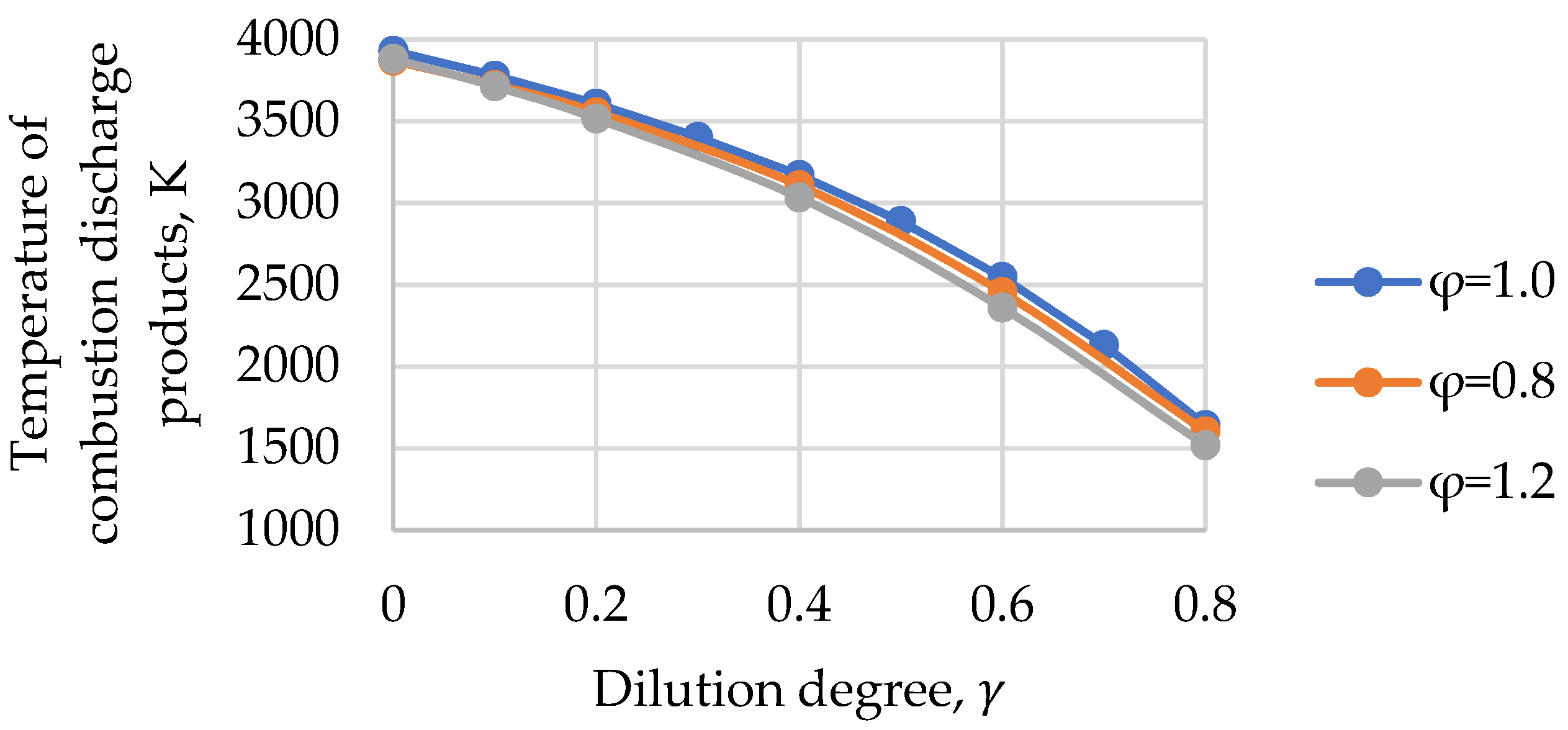
  • The highest level of adiabatic temperature was fixed at the stoichiometric mixture composition φ for 1.0 at any degree of dilution γ;
  • Changing the dilution degree γ from 0.1 to 0.3 reduces the normal flame propagation rate Un by 60.5% (from 959 to 378 cm/s) under supercritical parameters;
  • Limiting factors were defined for temperature values of combustion discharge in selecting the mixture composition as per mass-weight proportions;
  • The maximum dilution degree γmax for 0.6 was defined, at which stable burning is observed, exceeding this value results in a drop of the normal flame propagation rate Un below 70 cm/s, which may lead to flame decay;
  • The high fuel combustion efficiency ηb was achieved at 98.94% assessed as per mole fraction of unburnt fuel at the outlet section of the chamber.
Further research requires a study of the qualitative influence of geometrical factors and mixture parameters on the burning process in a three-dimensional setting, the definition of numerical values for target parameters, and the definition of measures for the development of efficient GTP hydrogen-oxygen combustion chambers.
Further three-dimensional modeling of burning may use the kinetic mechanism USC-II; the results of the calculation thereof match the results of the testing, with errors being below 5%.

Author Contributions

Conceptualization, A.R.; methodology, D.K.; software, T.K.; validation, T.K.; formal analysis, I.S.; investigation, I.S.; resources, T.K.; data curation, T.K.; writing—original draft preparation, D.K.; writing—review and editing, N.R.; visualization, D.K.; supervision, N.R.; project administration, A.R. All authors have read and agreed to the published version of the manuscript.

Funding

This study: conducted by the Moscow Power Engineering Institute, was financially supported by the Ministry of Science and Higher Education of the Russian Federation (project No. FSWF-2020–0020).

Data Availability Statement

Not applicable.

Conflicts of Interest

The authors declare no conflict of interest. The funders had no role in the design of the study; in the collection, analyses, or interpretation of data; in the writing of the manuscript; or in the decision to publish the results.

References

  1. Energy Strategy of the Russian Federation for the Period up to 2035. Government of the Russian Federation Order. No. 1523-R. 2020; p. 31. Available online: https://minenergo.gov.ru/sites/default/files/documents/11/10/1920/document-66308.pdf (accessed on 15 November 2022).
  2. United Nations Framework Convention on Climate Change. Conference of the Parties. Twenty First Session Paris. 2015. Available online: https://unfccc.int/resource/docs/2015/cop21/eng/10.pdf (accessed on 15 November 2022).
  3. Akhmetzhanov, R.; Gordeev, S.; Kanev, S.; Melnikov, A.; Nazarenko, I.; Khartov, S. Estimation of parameters of radio-frequency ion injector with an additional magnetostatic field. Acta Astronaut. 2021, 194, 524–531. [Google Scholar] [CrossRef]
  4. Habiballah, M.; Orain, M.; Grisch, F.; Vingert, L.; Gicquel, P. Experimental studies of high-pressure cryogenic flames on the mascotte facility. Combust. Sci. Technol. 2006, 178, 101–128. [Google Scholar] [CrossRef]
  5. Chehroudi, B. Recent Experimental Efforts on High-Pressure Supercritical Injection for Liquid Rockets and Their Implications. Int. J. Aerosp. Eng. 2012, 2012, 121802. [Google Scholar] [CrossRef] [Green Version]
  6. Reference Fluid Thermodynamic and Transport Properties-REFPROP; Version 10.0; National Institute of Standards and Technology, Standard Reference Data Program: Gaithersburg, MD, USA, 2018.
  7. Borzenko, V.I.; Schastlivtsev, A.I. Efficiency of Steam Generation in a Hydrogen-Oxygen Steam Generator of Kilowatt-Power Class. High Temp. 2018, 56, 927–932. [Google Scholar] [CrossRef]
  8. Komarov, I.; Kharlamova, D.; Makhmutov, B.; Shabalova, S.; Kaplanovich, I. Natural Gas-Oxygen Combustion in a Super-Critical Carbon Dioxide Gas Turbine Combustor. Russia E3S Web Conf. 2020, 178, 01027. [Google Scholar] [CrossRef]
  9. Rogalev, A.; Rogalev, N.; Kindra, V.; Komarov, I.; Zlyvko, O. Research and Development of the Oxy-Fuel Combustion Power Cycles with CO2 Recirculation. Energies 2021, 14, 2927. [Google Scholar] [CrossRef]
  10. Yang, S.; Yang, X.; Wu, F.; Ju, Y.; Law, C.K. Laminar flame speeds and kinetic modeling of H2/O2/diluent mixtures at sub-atmospheric and elevated pressures. Proc. Combust. Inst. 2017, 36, 491–498. [Google Scholar] [CrossRef] [Green Version]
  11. Kuznetsov, M.; Redlinger, R.; Breitung, W.; Grune, J.; Friedrich, A.; Ichikawa, N. Laminar burning velocities of hydrogen-oxygen-steam mixtures at elevated temperatures and pressures. Proc. Combust. Inst. 2011, 33, 895–903. [Google Scholar] [CrossRef]
  12. Aminov, R.Z.; Egorov, A.N. Hydrogen-oxygen steam generator for a closed hydrogen combustion cycle. Int. J. Hydrog. Energy 2019, 44, 11161–11167. [Google Scholar] [CrossRef]
  13. Aminov, R.Z.; Bayramov, A.N.; Schastlivtsev, A.I. Experimental evaluation of the composition of the steam generated during hydrogen combustion in oxygen. High Temp. 2020, 58, 410–416. [Google Scholar] [CrossRef]
  14. Santner, J.; Dryer, F.L.; Ju, Y. The effects of water dilution on hydrogen, syngas, and ethylene flames at elevated pressure. Proc. Combust. Inst. 2013, 34, 719–726. [Google Scholar] [CrossRef]
  15. Borzenko, V.I.; Schastlivtsev, A.I. Hydrogen-Oxygen Superheater. Federal State Budgetary Institution of Science Joint Institute of High Temperatures of the Russian Academy of Sciences (OIVT RAN) (RU). Patent No. RU185454U1, 5 December 2018. [Google Scholar]
  16. Pirashvili, S.A.; Guryanov, A.I. Vortex Hydrogen-Oxygen Combustion Chamber. Federal State Budgetary Educational Institution of Higher Professional Education «Rybinsk State Aviation Technical University named after P.A. Solovyov» (RU). Patent No. RU2539243C2, 20 January 2015. [Google Scholar]
  17. Pirashvili, S.A.; Guryanov, A.I.; Vereshchagin, I.M. Countercurrent Hydrogen-Oxygen Combustion Chamber. Federal State Budgetary Educational Institution of Higher Professional Education «Rybinsk State Aviation Technical University named after P.A. Solovyov» (RU). Patent No. RU2536646C1, 27 December 2014. [Google Scholar]
  18. Guryanov, A.I.; Pirashvili, S.A.; Guryanova, M.M.; Evdokimov, O.A.; Veretennikov, S.V. Counter-current hydrogen-oxygen vortex combustion chamber. Thermal physics of processing. J. Energy Inst. 2020, 93, 634–641. [Google Scholar] [CrossRef]
  19. Aminov, R.Z.; Bayramov, A.N. Hydrogen Combustion System for Steam-Hydrogen Superheating of Fresh Steam in the Cycle of a Nuclear Power Plant. Patent No. RU2427048C2, 20 August 2011. [Google Scholar]
  20. Borzenko, V.I.; Shchastyantsev, A.I. Hydrogen Steam Heater of Megwatt Power Level. Federal State Budgetary Institution of Science Joint Institute of High Temperatures of the Russian Academy of Sciences (OIVT RAN) (RU). Patent No. RU199761U1, 21 September 2020. [Google Scholar]
  21. Drozdov, I.G.; Shmatov, D.P.; Borzenko, V.I.; Kruzhaev, K.V.; Ignatov, A.S.; Shchastyantsev, A.I.; Timoshinova, T.S.; Levin, V.S.; Basharina, T.A.; Sviridov, I.E.; et al. Utility Model RU201875; Voronezh State Technical University: Voronezh, Russia, 2021. [Google Scholar]
  22. Kee, R.J.; Rupley, F.M.; Miller, J.A.; Coltrin, M.E.; Grcar, J.F.; Meeks, E.; Moffat, H.K.; Lutz, A.E.; Dixon-Lewis, G.; Smooke, M.D.; et al. CHEMKIN Release 4.1.1; Reaction Design: San Diego, CA, USA, 2007; 180p, Available online: https://personal.ems.psu.edu/~radovic/CHEMKIN_Tutorials.pdf (accessed on 15 November 2022).
  23. Wang, H.; You, X.; Joshi, A.; Davis, S.; Laskin, A.; Egolfopoulos, F.; Law, C.K. High-Temperature Combustion Reaction Model of H2/CO/C1–C4 Compounds. University of Southern California Mechanisms Version II. Combustion Kinetics Laboratory. Aerospace and Mechanical Engineering. 2007. Available online: http://ignis.usc.edu/USC_Mech_II.htm (accessed on 15 November 2022).
  24. Ji, C.; Wang, D.; Yang, J.; Wang, S. A comprehensive study of light hydrocarbon mechanisms performance in predicting methane/hydrogen/air laminar burning velocities. Int. J. Hydrog. Energy 2017, 42, 17260–17274. [Google Scholar] [CrossRef]
  25. Jithina, E.V.; Dinesh, K.; Mohammad, A.; Velamati, R.K. Laminar burning velocity of n-butane/Hydrogen/Air mixtures at elevated temperatures. Energy 2019, 176, 410–417. [Google Scholar] [CrossRef]
  26. Li, Z.; Cheng, X.; Wei, W.; Qiu, L.; Wu, H. Effects of hydrogen addition on laminar flame speeds of methane, ethane and propane: Experimental and numerical analysis. Int. J. Hydrog. Energy 2017, 42, 24055–24066. [Google Scholar] [CrossRef]
  27. Malenkov, A.S.; Kharlamova, D.M.; Naumov, V.Y.; Karev, T.P. Features of methane-hydrogen mixtures combustion in oxy-fuel power cycle combustion chamber. IOP Conf. Ser. Earth Environ. Sci. 2022, 1, 012143. [Google Scholar] [CrossRef]
Figure 1. The heat flow diagram of a power unit heated with a HCC; HPT—high-pressure turbine; IPT—intermediate-pressure turbine; LPT—low-pressure turbine; HPH—high-pressure heater; LPH—low-pressure heater; FP—feed pump; OC—oxygen compressor; HC—hydrogen compressor; and EG—electric generator.
Inventions 08 00006 g001
Figure 2. Straight-flow hydrogen-oxygen combustion chamber.
Inventions 08 00006 g002
Figure 3. Reactor diagram for burning in HOSS as per Ansys Chemkin-Pro; 1—oxidizer entry (mixture of oxygen and steam); 2—hydrogen entry; 3—mixing zone for oxidizer and fuel; 4—entry for supply of water vapor; 5—burning zone; 6—outlet collector (afterburn stage); 7—combustion discharge recirculation zone; and 8—outlet section.
Inventions 08 00006 g003
Figure 4. Change of adiabatic temperature of combustion discharge products at φ = 1.0, φ = 0.8, and φ = 1.2.
Inventions 08 00006 g004
Figure 5. Changes of normal flame propagation rate at a dilution of mixture with water vapor as per Ansys Chemkin-Pro at φ = 1.0.
Inventions 08 00006 g005
Figure 6. Dependence of fuel combustion efficiency on degree of dilution with water vapor as per Chemkin-Pro.
Inventions 08 00006 g006
Table 1. Comparison of the thermophysical properties of water vapor.
Water Pressure and ConditionThermal Diffusivity, α, cm2/sKin. Viscosity, ν, cm2/s Heat   Capacity ,   C p i ,   ( k J k g · K ) Thermal Conductivity, κ, ( m W m · K )   Density, ρ, kg/m3
P = 0.1 MPa, T = 813 K, water vapor1.1331.252.1672.10.27
P = 5 MPa, T = 813 K, water vapor0.0220.0242.3275.613.8
P = 23 MPa, T = 813 K, water vapor0.0040.0043.1896.772.7
P = 0.1 MPa, T = 1173 K, water vapor2.3862.7312.41121.70.18
P = 5 MPa, T = 1173 K water vapor0.0480.05432.45123.89.29
P = 23 MPa, T = 1173 K water vapor0.0100.01192.6135.643.6
P = 0.1 MPa, T = 293 K, liquid water0.0100.00144.18598.5998.2
Table 2. Power unit net efficiency with the turbine coolant steam taken from the boiler headers at the initial temperature of 993 K.
PropertyUnitsInlet HCCOutlet HCC
Steam pressure MPa23.522.325
Steam temperaturesK8131173
Mass flow rate of steamkg/s184.5-
Table 3. Basic parameters for calculation.
Component NameTemperature,
T i ,   K
Mass   Consumption   of   Component ,   m ˙ i ,   kg / s Pressure,
P i ,   MPa
Specific   Heat   Capacity ,   C P i ,   kJ / kg · K
H2O813185.523.53.214
H2490.61.71824.714.67
O2485.513.6324.71.07
Table 4. Basic parameters for the calculation and obtained mole fraction of unburnt hydrogen.
Dilution Degree,
γ
Mass   Consumption   of   Oxidizer ,   m ˙ o x ,   kg / s Mole   Fraction   of   Oxygen ,   x m   O 2 Mole   Fraction   of   Water ,   x m   H 2 O Adiabatic   Temperature ,   T a d   and   K Mole   Fraction   of   Unburnt   Hydrogen ,   x H 2 n b
013.6300.8890.1113931 1.24 × 10 4
0.115.3350.7800.2203779 1.15 × 10 4
0.217.4670.6740.3263607 1.17 × 10 4
0.320.2080.5710.4293405 1.17 × 10 4
0.423.8620.4700.5303171 1.14 × 10 4
0.528.9780.3720.6282889 1.02 × 10 4
0.636.6520.2760.7242547 7.56 × 10 4
0.749.4420.1820.8182132 7.67 × 10 4
0.875.0220.0900.9101642 7.77 × 10 4
0.9151.7621.00001.117 1.77 × 10 3
Table 5. Dependence of combustion efficiency on degree of dilution with the water vapor.
Dilution Degree,
γ
Number   of   Moles   of   Unburnt   Hydrogen ,   n H 2 n b ,   Mole Efficiency of Combustion, ηb, %
01.4999.83
0.11.3799.84
0.21.4199.84
Disclaimer/Publisher’s Note: The statements, opinions and data contained in all publications are solely those of the individual author(s) and contributor(s) and not of MDPI and/or the editor(s). MDPI and/or the editor(s) disclaim responsibility for any injury to people or property resulting from any ideas, methods, instructions or products referred to in the content.

