The Design of an Infeed Cylindrical Grinding Cycle


Advanced Finishing Technology Ltd., Akron, OH 44319, USA
Inventions 2020, 5(3), 46; https://doi.org/10.3390/inventions5030046
Submission received: 6 August 2020
/
Revised: 20 August 2020
/
Accepted: 21 August 2020
/
Published: 28 August 2020
(This article belongs to the Special Issue Modern Grinding Technology and Systems 2019)
Abstract
:This paper synthesizes the design of an infeed cylindrical grinding system into a total system composed of the grinding mechanism and the grinding machine characteristics. The causalities between the grinding parameters and the machine structures are discussed, and the infeed grinding processes are analyzed as outputs that represent responses to the inputs. These relationships are integrated into a block diagram with closed-loop feedback. A novel model exhibiting practical parameters such as grinding speed, infeed rate and MRR (Material Removal Rate) is proposed. The analysis of the grinding system derived a critical factor, the “grinding time contact,” which governs the transient behaviors of process parameters such as forces and machine deflection. The process parameters during the infeed cycle including spark-out grinding were investigated, and the formulas required for the cycle design are presented. Furthermore, to improve accuracy and productivity, the features of the cycle design are described and procedures for controlling size error and roundness are discussed. Finally, the model was verified with infeed grinding tests applied to both the chuck-type cylindrical and centerless grinding methods.
1. Introduction
In general, the term “cylindrical grinding” describes a group of grinding processes, the common characteristic of which is the rotation of the workpiece around a fixed axis [1]. However, this paper extends the field of cylindrical grinding to the centerless-support grinding methods, which do not use a fixed axis for workpiece rotation. This paper discusses the infeed (plunge) grinding of the outer diameter of the cylindrical and ring workpieces; the relevant methods to be addressed are chuck- center type cylindrical grinding, centerless grinding and shoe-centerless grinding.
In infeed cylindrical grinding, the grinding cycle must be designed based on quality and productivity demands. Usually the cycle includes grinding processes for roughing, semi-finishing and finishing, and at the end of the cycle, spark-out grinding is performed to release the machine elastic deflection caused by the grinding forces. Production engineers must make decisions about the infeed rate, the grinding stock for each process and the spark-out time; they need to estimate what the productivity based on the cycle time should be, and must determine grinding quality standards for factors such as size error and roundness. It is crucial for engineers to fully understand the behaviors of grinding parameters during the cycle and the influence of the grinding machine on the grinding processes.
Early research on grinding was conducted by Schlesinger in 1936 [2]. Since then, many researchers have performed extensive studies and today, grinding fundamentals are well established [3,4]. The relationships among the fundamental parameters in infeed cylindrical grinding have been presented by Malkin, Levin, et al. and others [5,6,7,8]. Further, many kinds of grinding models have been proposed and the simulations are making great contributions to the production industry [9,10,11]. Chiu et al. has presented a simulation of the grinding parameters specific to infeed cylindrical grinding [12].
The influences of grinding machine characteristics on the grinding processes have been investigated as well [13,14,15,16]. Tobias revealed the dynamic characteristics of the machine tools [17], and the design methods of machine tools have also been presented [18,19,20]. In particular, the effects of the dynamics of machine structures on self-excited chatter vibrations have been discussed, and the theory known as “regenerative chatter vibration” has been well developed [21,22,23].
In the production engineering societies, both grinding fundamentals and machine tool characteristics are well understood, and many analytical models have been presented [24,25]. However, it is common that industrial engineers who understand both areas well still have difficulty applying their knowledge to the design of the grinding cycle and the prediction of grinding performance. They also lack practical tools to optimize infeed grinding processes based on the characteristics of the grinding machine being used. These issues may be arising from the fact that infeed cylindrical grinding is not treated as a total grinding system. Therefore, the grinding fundamentals and the machine characteristics are not holistically integrated, and the causalities among the system parameters are not made clear.
Another reason could be the disconnection between the scientific parameters used in past proposed models and the practical parameters used in real-world grinding operations. In order to optimize infeed grinding processes with the required grinding performance and productivity, it is essential to synthesize the infeed cylindrical grinding process from the viewpoints of both the grinding and machine tool technologies. Industrial engineers should be equipped with practical tools for designing the grinding cycle and determining operational conditions such as feed rates, stock assignments, specific material removal rate (SMRR) and spark-out times.
The objective of this study was to treat the various components of infeed cylindrical grinding as an overall system. Thus, this proposed system contains the grinding mechanism, the grinding fundamental parameters and the characteristics of the grinding machine structures. The causalities between the grinding parameters and the machine tools are discussed, and the infeed grinding processes are analyzed as output responses to the operational inputs from the grinding machine. These relationships are integrated into a block diagram with closed-loop feedback. A novel model exhibiting practical parameters like grinding speed, infeed rate and MRR is presented. The proposed model is directly applicable for the practical setup and grinding operations in both cylindrical and centerless grinding.
The analysis of the grinding system derived a critical factor, the “grinding time constant,” which governs the transient behaviors of process parameters, such as forces and machine deflection. The process parameters used during the infeed cycle (including spark-out grinding) were investigated, and the formulas required for the cycle design are shown. Furthermore, to improve accuracy and productivity, the features of the cycle design are described and procedures for controlling size error and roundness are discussed. Finally, the model was verified with infeed grinding tests applied to both grinding methods: chuck type cylindrical grinding and centerless grinding.
2. Cylindrical Grinding System
2.1. Models of Grinding Systems
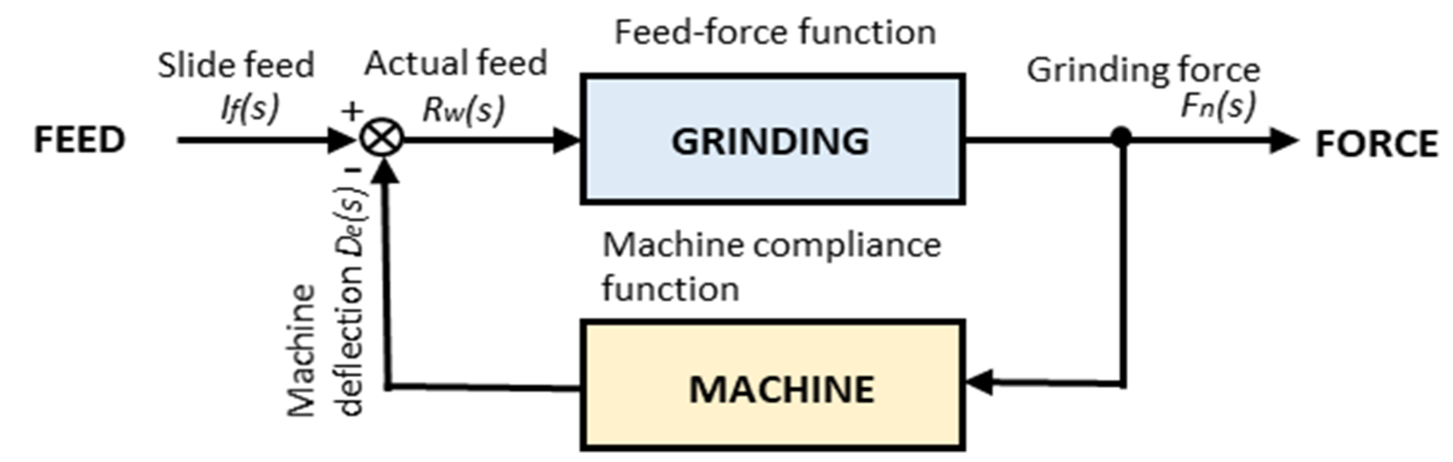
A general grinding system can be represented as a closed-loop system, as shown in Figure 1. The system is composed of two functions. One is the feed-force function based on the grinding mechanism, and the other is the compliance function of the grinding machine. In a grinding machine, an infeed slide with a grinding wheel head is fed into the workpiece and an amount of interference between the wheel and the workpiece is specified. The grinding wheel removes materials from the workpiece as per the actual interference amount. The grinding and subsequent material removal result in the generation of grinding forces and cause the deflection of the machine structures in the infeed direction. Therefore, the actual amount of the interference becomes the difference between the command infeed and the machine deflection. This principle can be applied to most grinding systems, including surface grinding, cylindrical grinding, centerless grinding, shoe-centerless grinding, double disk grinding, etc.
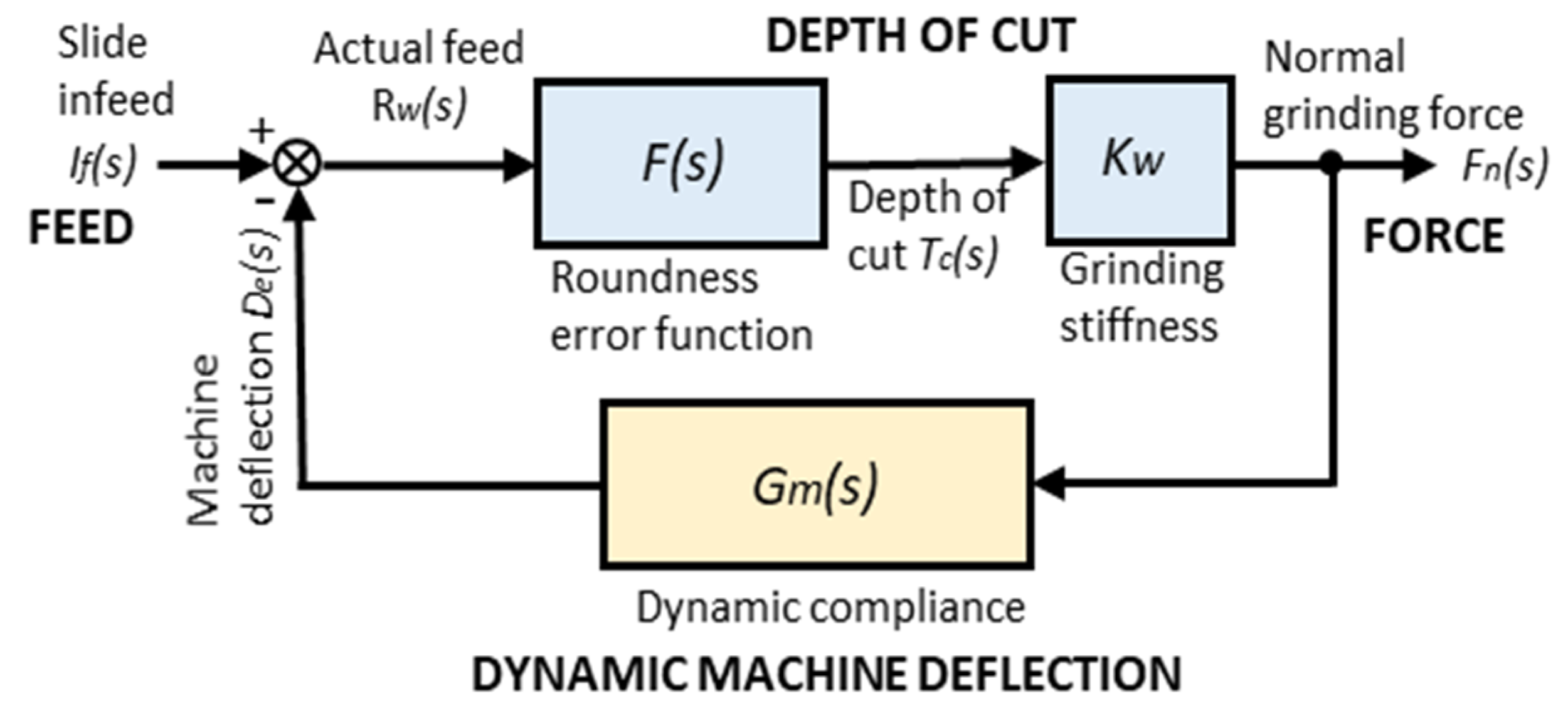
To investigate the regenerative self-excited vibrations in cylindrical grinding applications, including centerless grinding [11,14,21,22,23,25], several grinding models have been developed to date. Stability criteria to suppress the chatter vibrations have also been discussed. These models focus on the depth of cut per revolution of the workpiece, which is proportional to the grinding forces under given conditions. When the structure of the grinding machine is excited with the dynamic components of the grinding forces, the self-excited chatter vibrations occur. Thus, the models capture the dynamic characteristics of the grinding machine such as the natural frequencies and the damping factors.
From this point of view, these models can be classified within the dynamic grinding model shown in Figure 2. However, they are not suitable for addressing the fundamental parameters of the grinding processes because the grinding forces are determined by the material removal rates, not only by the depth of cut. In addition, the dynamic model does not directly present practical setup conditions, such as workpiece sizes, grinding speed and infeed rates.
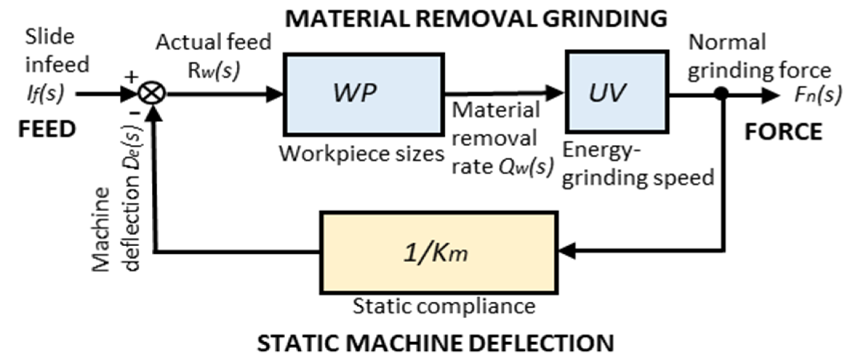
Figure 3 shows a novel grinding model that accounts for the various setup parameters of cylindrical grinding operations, including the material removal rate, workpiece sizes and grinding speed. In this model, only the static compliance of the grinding machine is considered for the grinding process analysis. The dynamic process behaviors should be analyzed by using the dynamic model (Figure 2). From this perspective, the model can be considered a static grinding model.
2.2. The Modeling of the Infeed Cylindrical Grinding System
2.2.1. The Fundamentals of Infeed Cylindrical Grinding
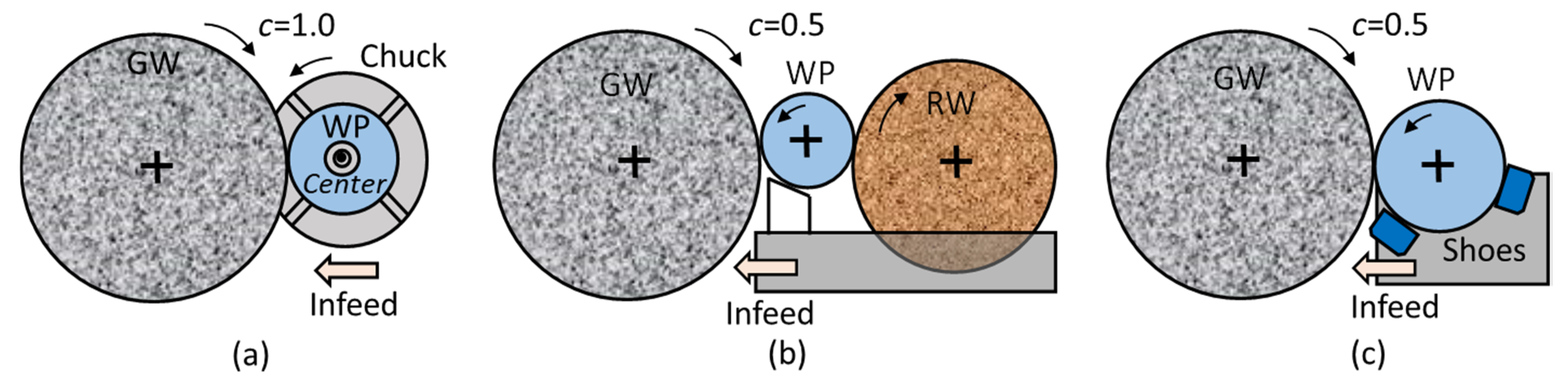
Figure 4a illustrates the center-chuck type method of cylindrical grinding. With this method, the amount of the infeed becomes the radial reduction of the workpiece, which is represented as the method parameter c = 1.0.
Figure 4b,c illustrates the centerless grinding method and the shoe-centerless grinding method, respectively. With these methods, the amount of the infeed becomes the diameter reduction of the workpiece. The method parameter c is assumed to be c = 0.5 in centerless methods.
The SMRR (specific material removal rate) Qw’ can be represented by:
where c is the grinding method parameter, is the diameter of the workpiece and is the infeed rate. The ordinary unit of SMRR is . That means represents the removed chip volume per unit width in unit time. The MRR (material removal rate) is:
where b is the width of the workpiece. The tangential grinding force is obtained by:
where u is the specific grinding energy with the unit of (J/mm3) and is the grinding speed. The normal grinding force is written by:
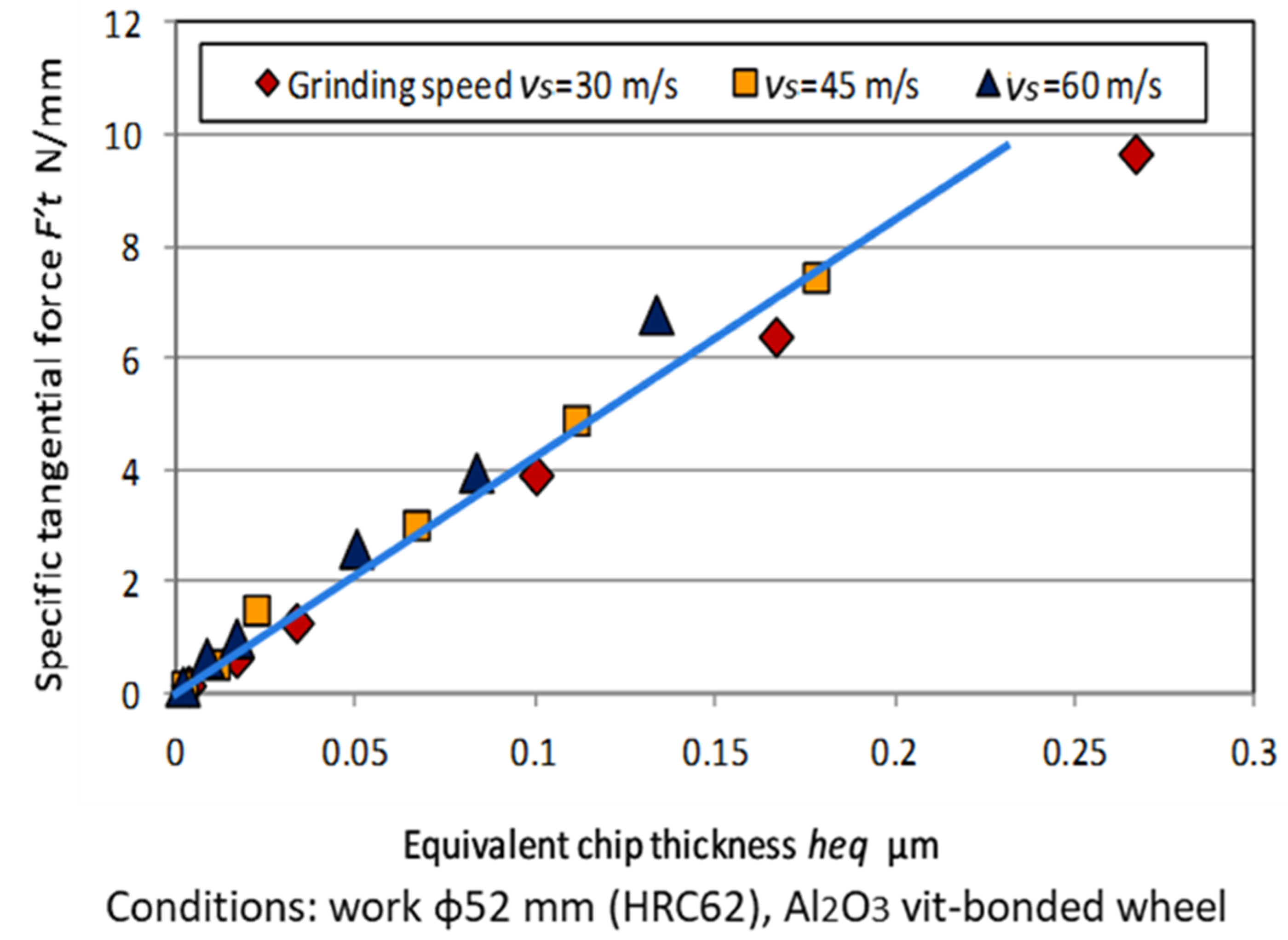
where η is the force ratio defined as . The equivalent chip thickness is defined as:
is one of the critical parameters, such as surface roughness and residual stresses, that govern grinding quality [3]. As shown in the above equations, the specific tangential grinding force has the following relationship with
Figure 5 is a graphical representation of the infeed cylindrical grinding test results showing the linear relationship between under the various grinding speeds. The grinding power with the ordinary unit of (kW) can be expressed by:
2.2.2. Machine Stiffness in the Grinding System
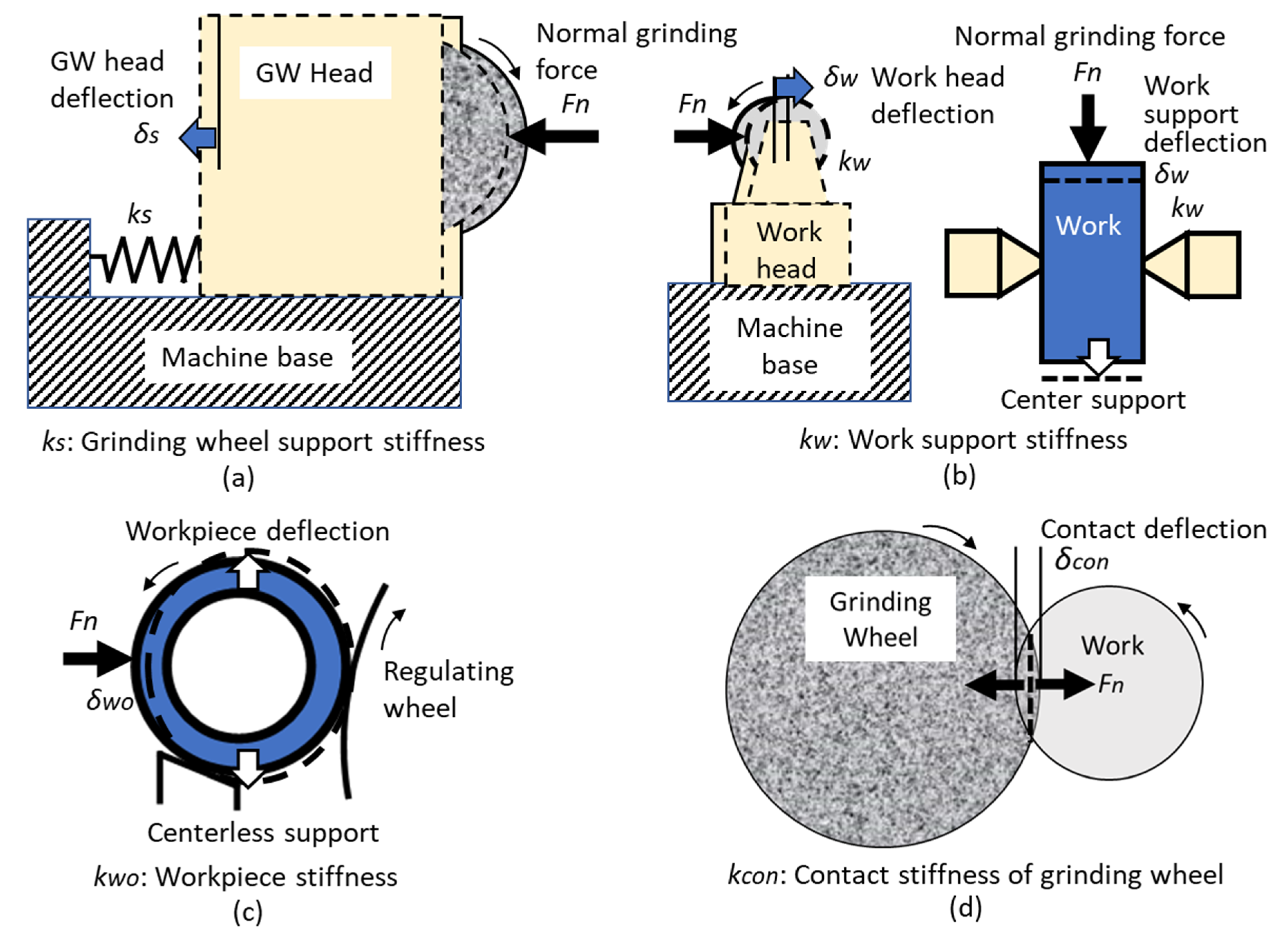
Figure 6 illustrates the stiffnesses of major structures in a grinding machine. In Figure 6a, is the deflection caused by the normal grinding force Fn acting on the grinding wheel head. ks is the stiffness of the grinding wheel support system represented by Fn/ Figure 6b shows the work support head and is the deflection of the work head support system caused by Fn. denotes the stiffness of the work head support system. In Figure 6c, represents the stiffness of the workpiece itself. A thin, ring-shaped workpiece sometimes has a low stiffness that cannot be ignored. Figure 6d shows the stiffness in the contact area between the grinding wheel and the workpiece, which is referred to as “contact stiffness” and is denoted by . In general, the contact stiffness of the grinding wheel has hard-spring characteristics in which the higher contact force provides the higher stiffness.
The grinding system stiffness , with the loop from the workpiece to the grinding wheel via the above stiffnesses shown in Figure 6a–d, can be represented by:
The compliance 1/km of the grinding system is found by the summation of all compliances discussed in Figure 6.
2.3. The Block Diagram of a Cylindrical Grinding System
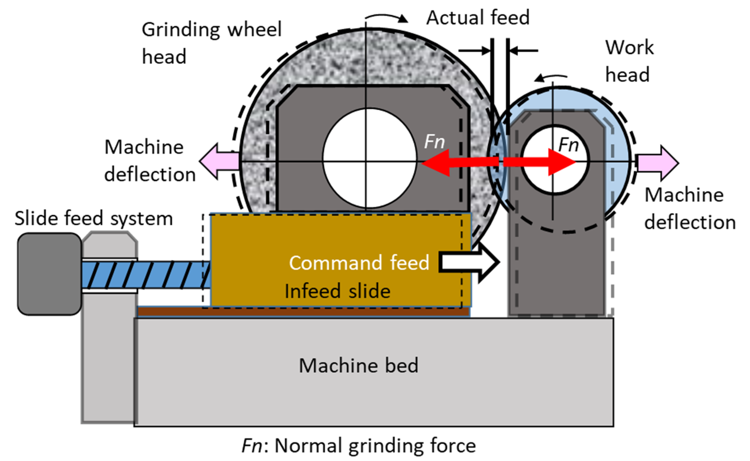
Figure 7 is the schematic of a cylindrical grinding machine. The grinding wheel mounted on the infeed slide is fed into the workpiece as a command infeed. The actual infeed can be expressed by:
where t is the grinding time and is the grinding machine deflection in the infeed direction given by Equation (14). The actual infeed rate is:
The SMRR is expressed by:
The MRR is:
The normal grinding force can be written as follows:
where η is the force ratio (Fn/Ft) and is the grinding speed. The elastic deflection of the grinding machine in the infeed direction can be expressed by:
The deflection given by Equation (14) is fed back to Equation (9). Thus, the infeed cylindrical grinding processes can be described as a closed-loop system repeating Equations (9)–(14).
By using Equations (11)–(13), Equation (14) can be rewritten as follows:
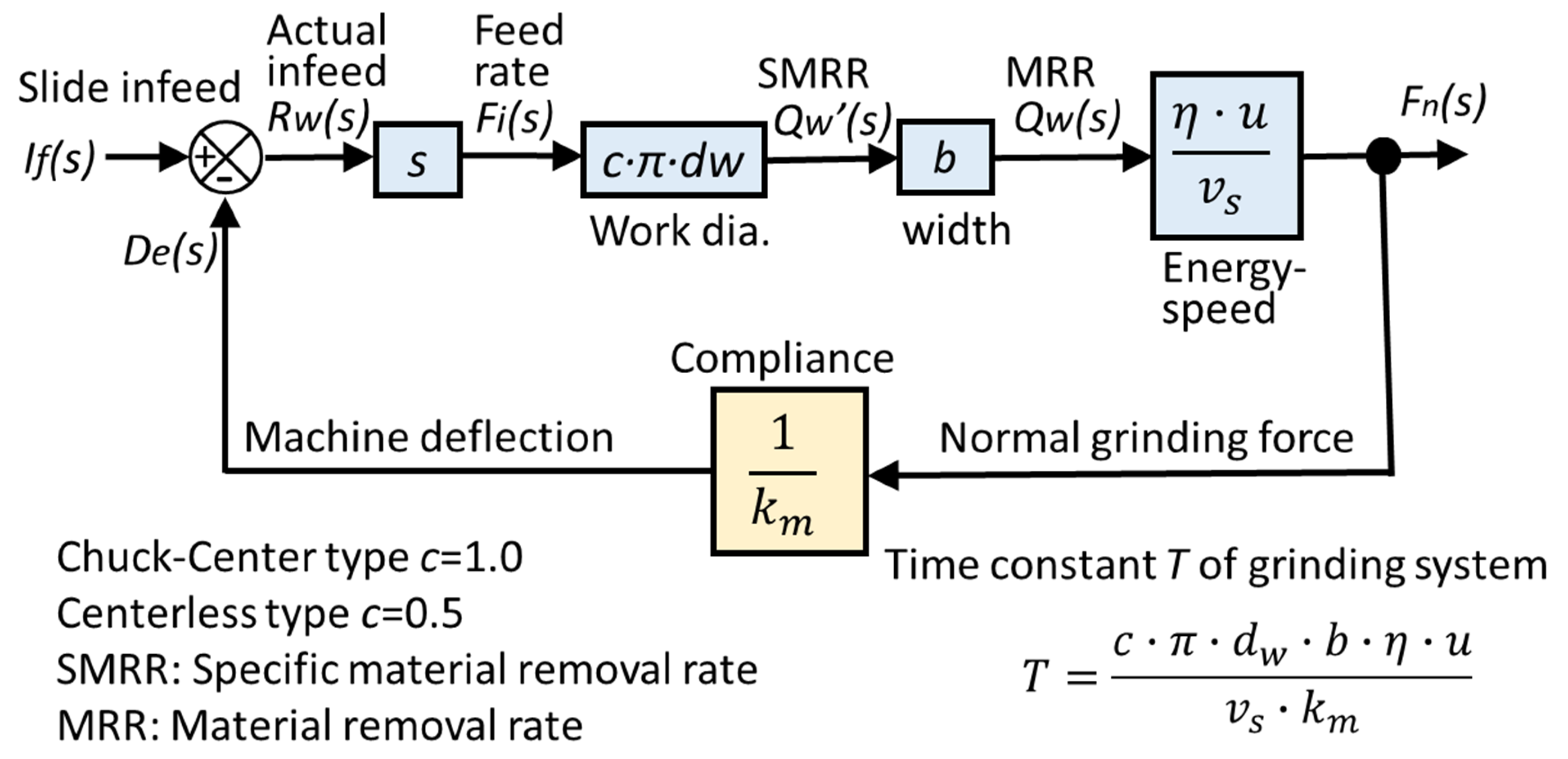
where T is the time constant of the grinding system in units of (s).
The time constant T is one of the most critical parameters in the cylindrical grinding system.
The Laplace transformation of Equations (9)–(14) leads to the following Equations:
where s is the Laplace operator. Actual infeed , actual infeed rate , SMMR normal grinding force and elastic deflection are Laplace functions.
Figure 8 shows the block diagram of the infeed cylindrical grinding system representing the transfer functions given by Equations (17)–(22). The infeed cylindrical grinding system can be expressed by a closed-loop feedback system. The transfer function G(s) of the system is represented by:
Thus, infeed cylindrical grinding can be represented by the first-order lag system with the time constant T given by Equation (16).
3. Responses to Command Infeed in a Cylindrical Grinding System
3.1. Responses to Step Infeed (Spark-Out Grinding)
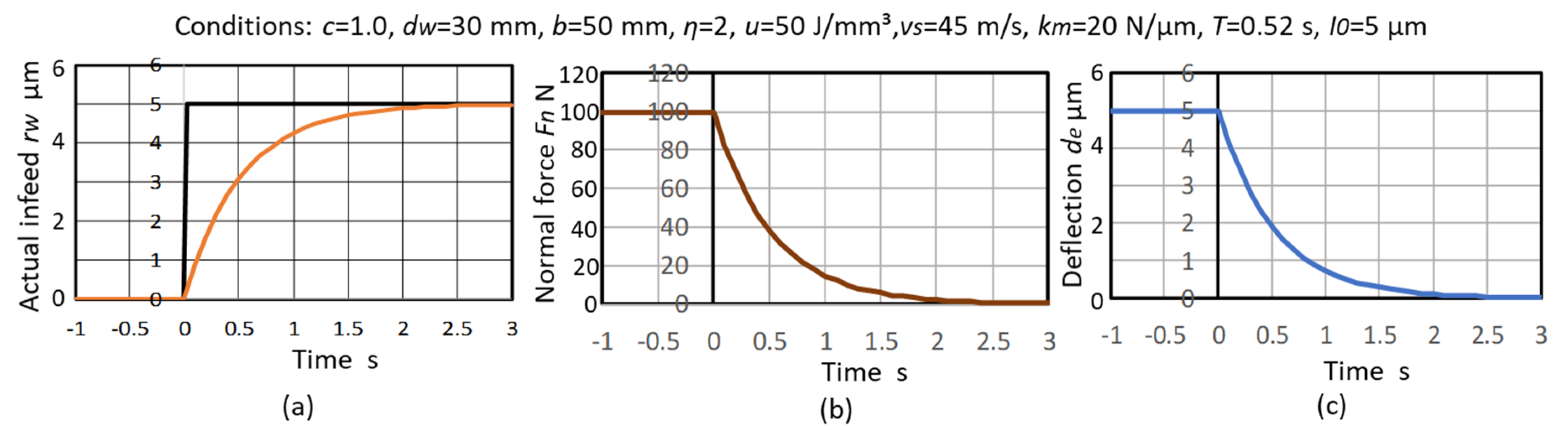
The spark-out in the infeed grinding cycle corresponds to the step response in the closed-loop feedback system. In order to simulate the spark-out process, it is assumed that the step command in the infeed slide position is given to the system.
The actual infeed rate can be expressed as follows (see Appendix A):
The actual infeed position , the normal grinding force and the deflection during spark-out grinding are obtained by:
Simulations of the changing processes of , and during spark-out grinding are shown in Figure 9a–c.
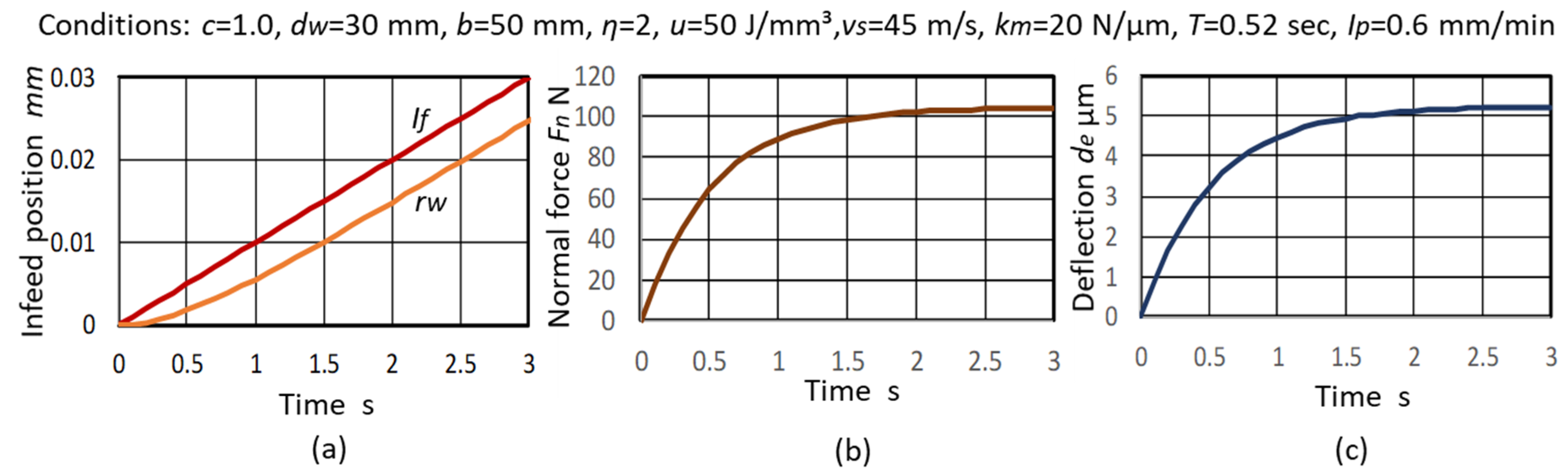
3.2. Responses to Ramp Infeed (Plunge Grinding)
Infeed grinding with a constant rate in the grinding cycle corresponds to the ramp response in a feedback system. To simulate the processes of infeed or plunge grinding with an infeed rate, it is assumed that the command of a ramp infeed as the input is given to the grinding system. The infeed command is shown as:
where is a constant infeed rate. The actual feed rate can be expressed as follows (see Appendix B):
The actual infeed position , the normal grinding force and the deflection during infeed (plunge) grinding can be obtained by:
Simulations of the changing processes of , and during the infeed grinding with a constant rate are shown in Figure 10a–c.
3.3. The Effects of the Time Constant on Infeed Grinding Processes
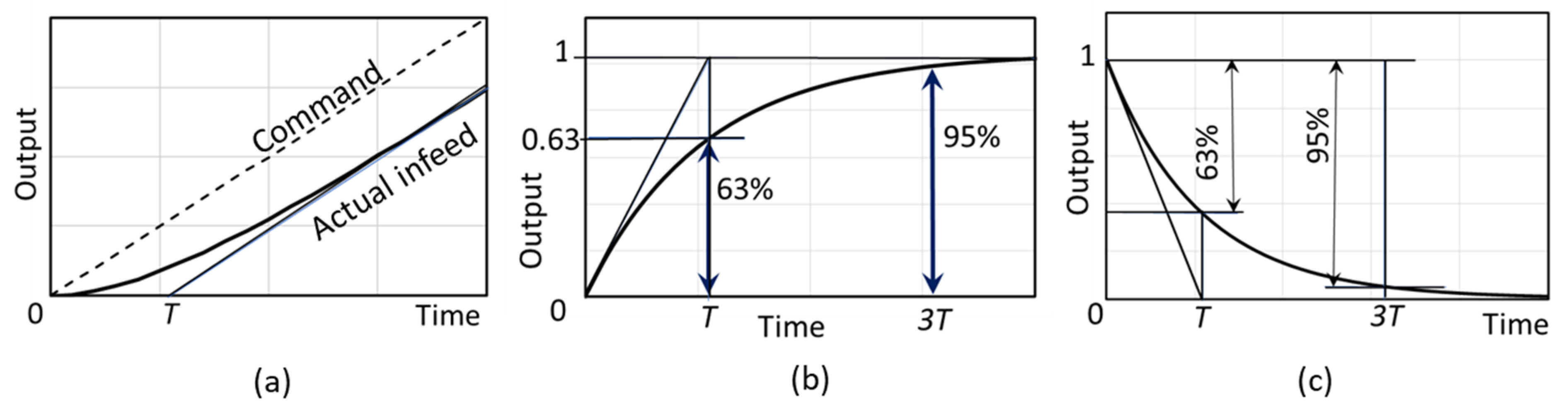
Figure 11 shows the effects of the time constant T on the infeed grinding processes. Figure 11a is the response to the ramp infeed command. The actual infeed position delays the command and gradually catches up. Eventually it attains the same slope as the command infeed. The asymptote of the actual infeed curve intersects at the time T of the horizontal axis.
Figure 11b shows the response of the normal grinding force and deflection to the ramp infeed. These outputs are gradually increased according to the response of the first-order lag system and finally reach a constant command input. The time constant T is defined as the time when the output reaches 63%. At three times the time constant (3T), the output reaches 95% of the command input.
Figure 11c is the spark-out response to the step infeed command. The output of the force or the deflection is gradually reduced and finally converges to zero. The time constant T is the time when the output is reduced by 63%. Again, 3T gives the 95% reduction.
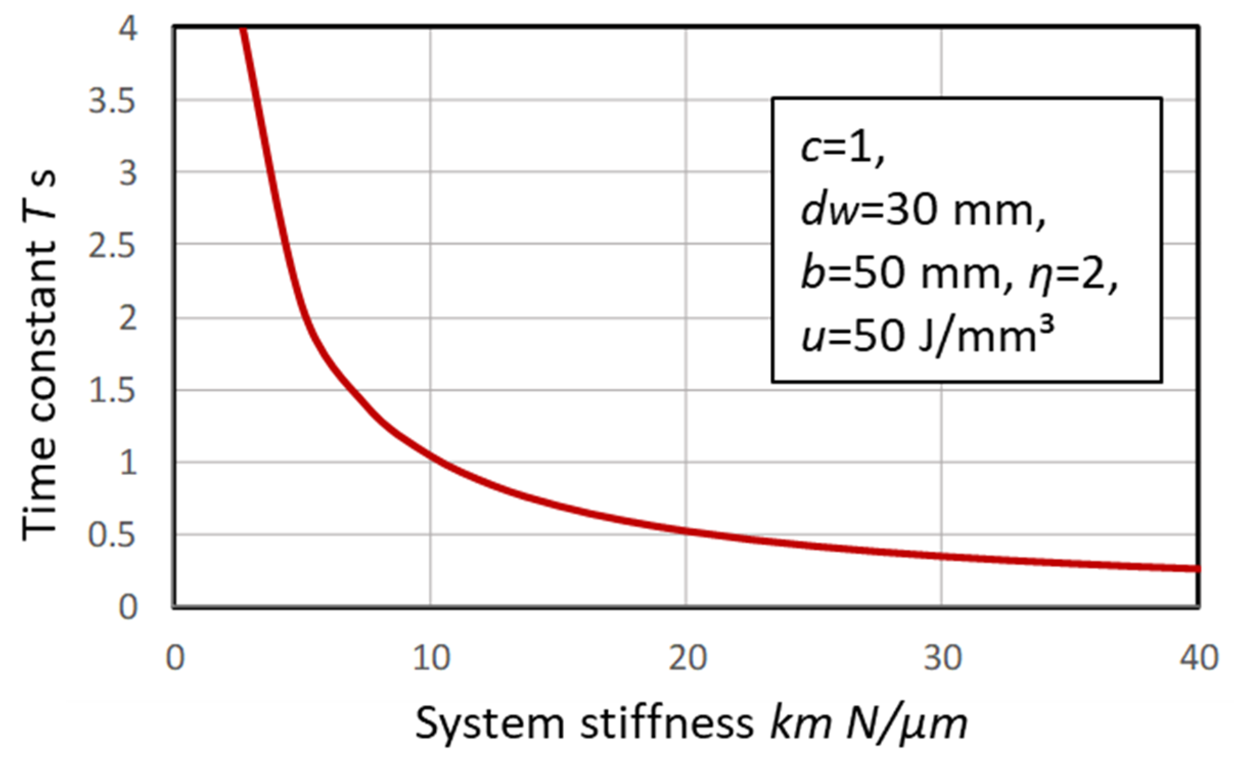
Figure 12 presents the relationship between the system stiffness km and the time constant T. As Equation (16) indicates, the higher the system stiffness, the shorter the time constant. The design with the more rigid grinding machine provides a shorter time constant T and reduces the spark-out time.
4. Grinding Cycle Design
4.1. Grinding Cycle
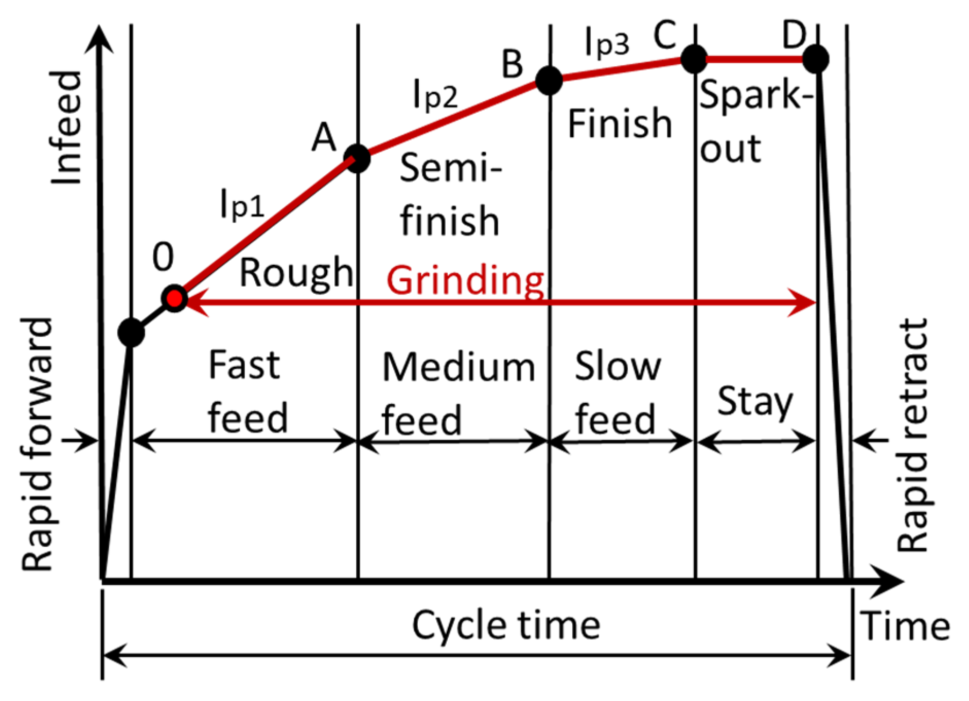
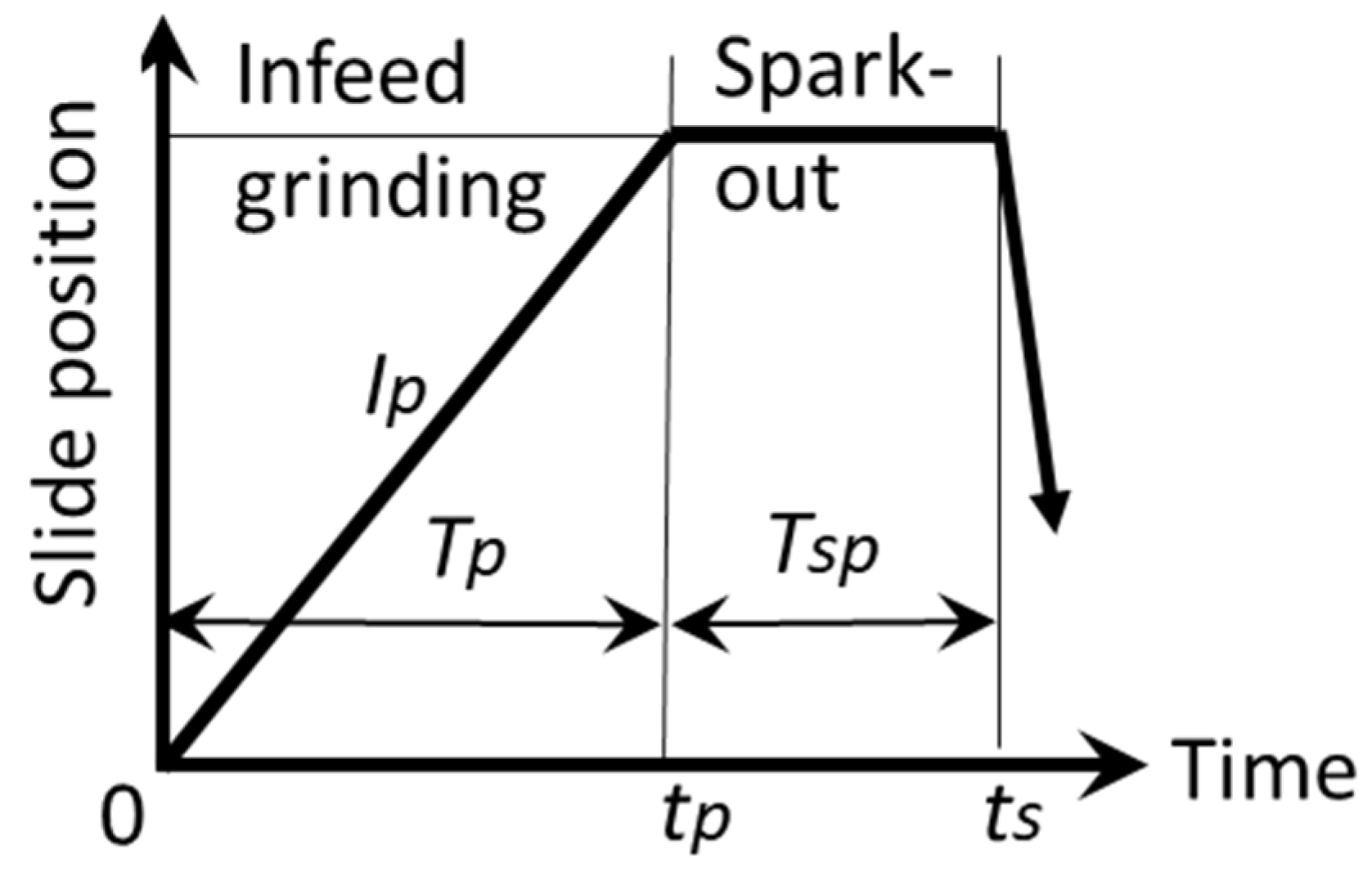
Figure 13 diagrams a typical infeed grinding cycle. At the home position of the infeed slide, a workpiece is loaded and starts to rotate. First, the infeed slide travels toward the workpiece with a rapid forward speed. Then, the slide approaches the workpiece with a fast feed rate appropriate for rough grinding. During the fast feed, at point O, the grinding wheel contacts the workpiece and the rough grinding starts. At point A, the infeed rate is reduced for semi-finish grinding. The infeed rate is further reduced at point B for finish grinding. At point C, the infeed slide stops and maintains its position for spark-out grinding. During the spark-out, the infeed slide retracts toward the home position with a rapid backward speed at point D.
It is critical for infeed grinding operations to determine the infeed positions O to D; the infeed rates and spark-out time based on the hard stock conditions; and the requirements for productivity. To design the grinding cycle, the following parameters should be considered and be quantitatively analyzed during the infeed grinding processes.
- i.
- Actual relative approaches between the grinding wheel and workpiece.
- ii.
- Actual infeed rates.
- iii.
- Grinding forces.
- iv.
- Elastic deflection of grinding machine.
The cycle time (CT) is defined as the total time from the home position to the home position via points O, A, B, C and D.
4.2. Analysis of Infeed Grinding Processes
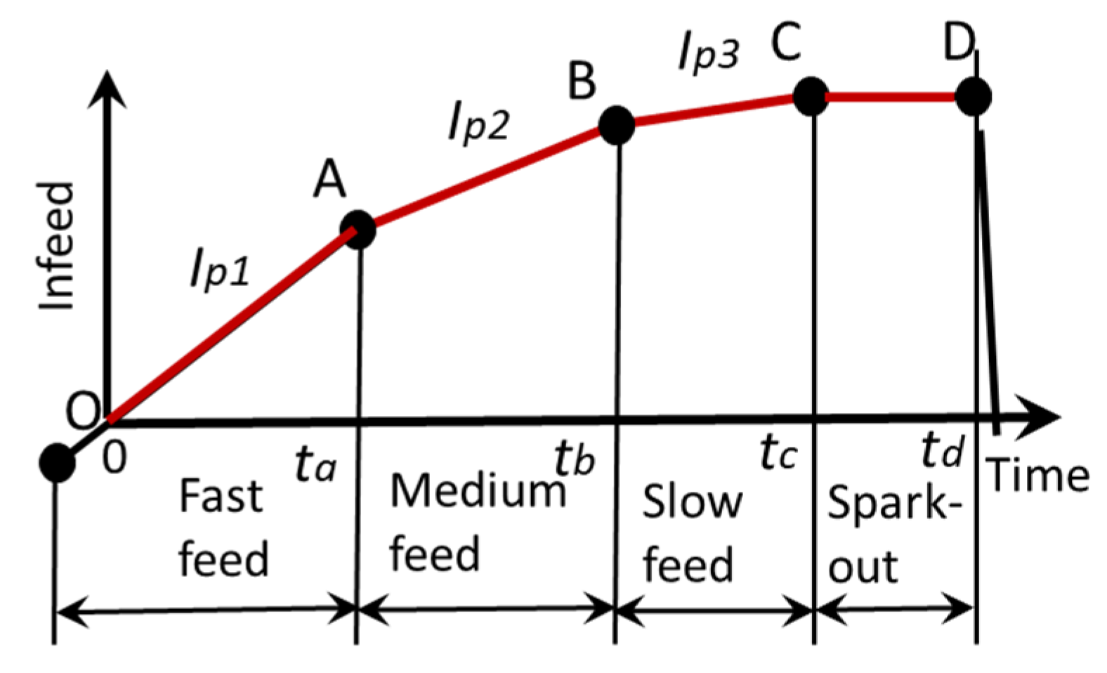
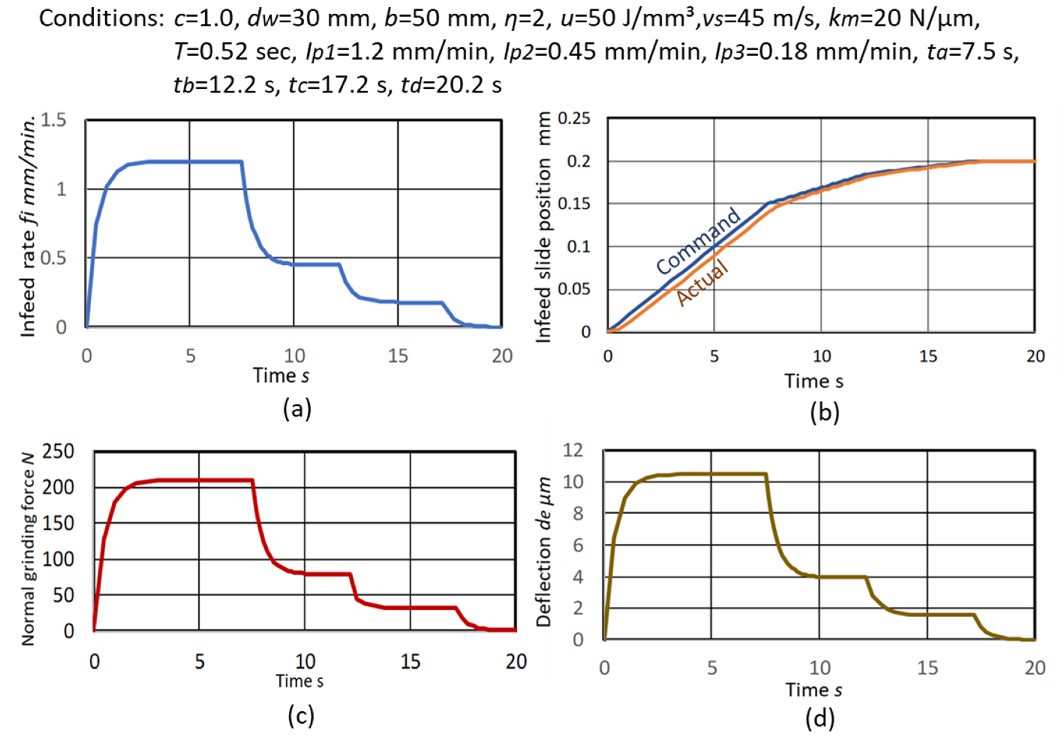
The grinding cycle setup for the analysis is shown in Figure 14. , and are the infeed rates for the rough, semi-finish and finish grinding operations, respectively. The infeed rate fi (t) during the cycle can be expressed by the following Equations.
The actual slide position during the cycle can be represented by:
The normal grinding force can be expressed by:
The deflection can be expressed by:
4.3. The Influence of the Time Constant on the Grinding Cycle
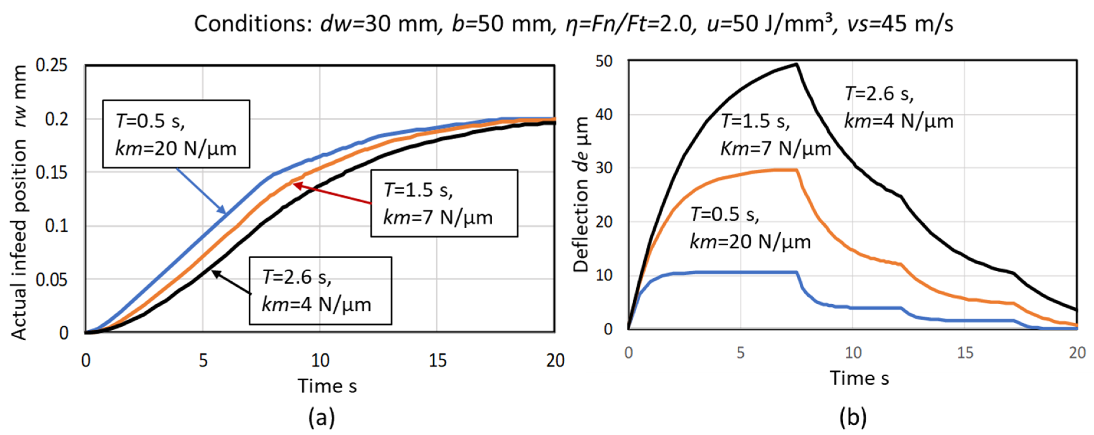
Figure 16 shows the influence of the time constant on the behaviors of the process parameters during infeed cylindrical grinding, assuming the typical cycle shown in Figure 14. The time delay becomes greater with the increased time constant T and the response to the command infeed becomes slower with lower system stiffness km, as shown in Figure 16a.
When the time constant T = 0.5 s as in Figure 16b, the deflection reaches a steady state at each operation from rough to finish grinding, and the final deflection at the end of the spark-out grinding becomes almost zero. This indicates that the grinding cycle is properly designed. On the other hand, when the time constant T = 1.5 s or 2.6 s, the deflection does not reach a steady state at each grinding operation and is still in a transient stage. The final deflections at the end of the spark-out grinding do not converge. It means that the size error of the workpiece is greater than that of T = 0.5 s, due to the remaining deflection. Additionally, it indicates that the stiffer machine provides the reduced time constant T and the smaller size error.
5. Grinding Accuracy and Stock Assignments
5.1. Size Error
In the primary grinding cycle shown in Figure 17, the deflection at the grinding time can be obtained by:
where is the infeed rate and is the infeed grinding time. When is sufficiently long enough compared to the time constant T, the deflection can be approximately represented by:
The elastic deflection of the grinding system at the final grinding time becomes the size error of the ground workpiece. Therefore, the size error in diameter can be found by:
where is the spark-out time. When the size error in diameter is required to be within , the spark-out time for achieving the objective can be obtained by:
5.2. Roundness
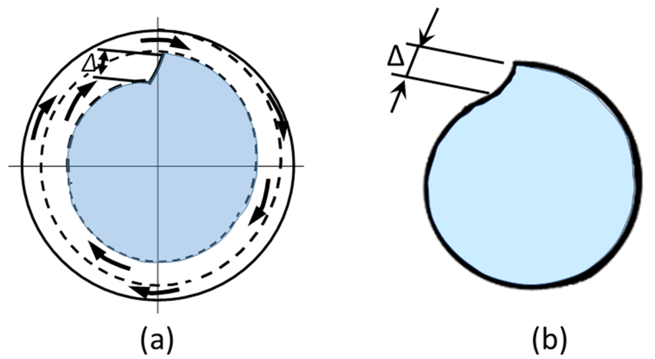
In infeed grinding, the depth of cut Δ per revolution of the workpiece is written by:
where is the rotational speed of the workpiece in rps. The depth of cut Δ is observed as a step on the roundness of the workpiece during infeed grinding, as shown in Figure 18. The step becomes the roundness error. The step-roundness Δ can be reduced by spark-out grinding.
In order to suppress the step-roundness to less than , the required spark-out time can be calculated by:
5.3. Grinding Stock Assignments and SMRR
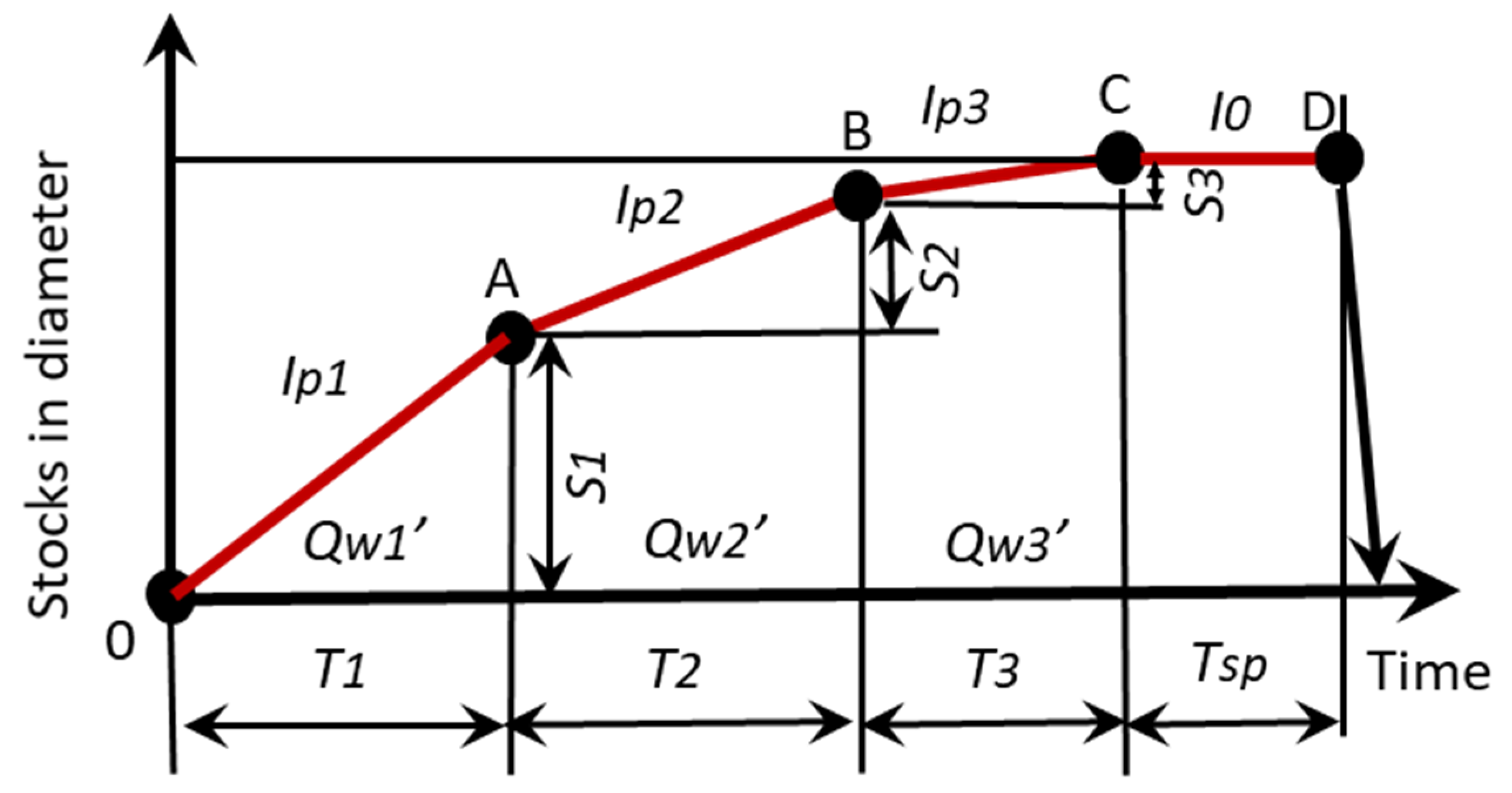
Figure 19 shows a grinding cycle diagram with SMRRs and grinding stocks for rough, semi-finish and finish grinding. The total stocks in diameter S consist of S1 for rough, S2 for semi-finish and S3 for finish grinding.
The SMRRs are assigned as for rough, for semi-finish and for finish grinding. The total grinding time is:
The infeed rate can be written by . So, the grinding time is rewritten by:
By setting the spark-out time to three times the time constant T, the size error can be reduced by 95% of the deflection generated during finish grinding. When the total stock S is assigned as %, %, and % for rough, semi-finish and finish grinding, respectively, the grinding time is presented by the following Equation.
6. Experimental Tests and Simulations
For the validation of the proposed model, cylindrical grinding tests on workpieces of through-hardened steel materials (HRC58) were conducted using the chuck-center type cylindrical grinding method (c = 1.0). The detailed grinding conditions are shown in Table 1.
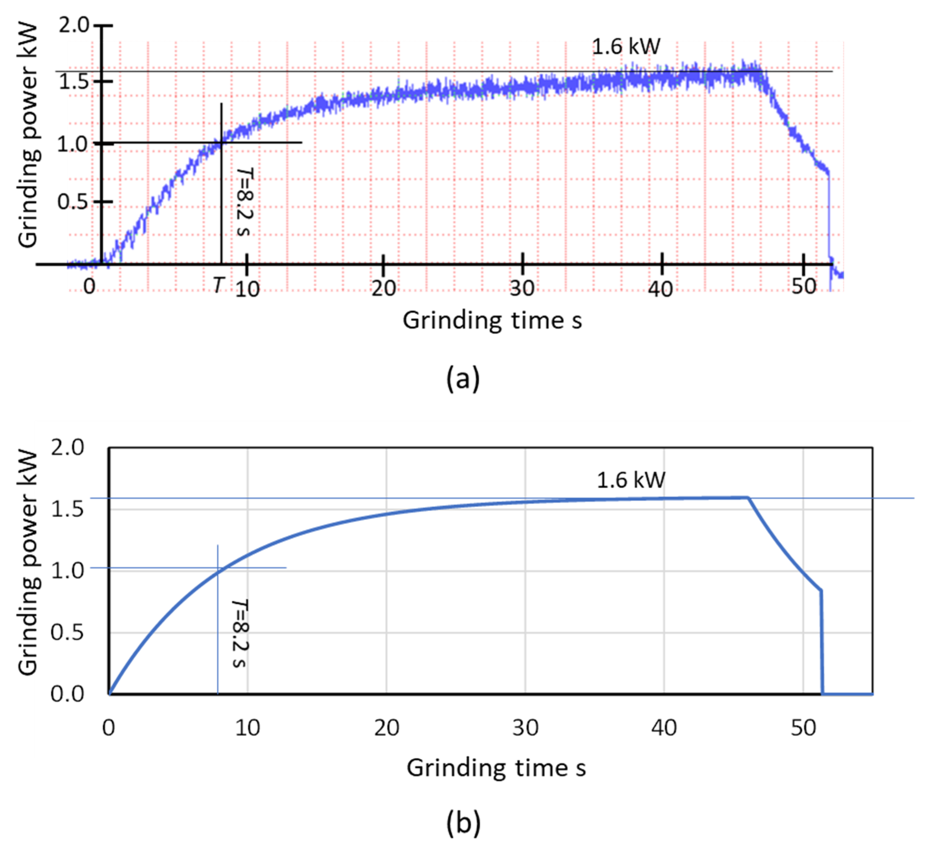
The grinding power was measured during the infeed grinding and the results are shown in Figure 20a. The grinding power in the steady state was 1.6 kW, and a time constant T = 8.2 s was found at the time the power reached 63% of 1.6 kW. The specific energy u can be calculated by Equation (7), obtaining u = 26.7 J/mm3. Additionally, the system stiffness km can be found by Equation (16), obtaining km = 2421 N/mm.
The simulation results calculated by using the grinding conditions (Table 1) and parameters obtained from the grinding tests (Figure 20a) are shown in Figure 20b. In the simulation, the build-up behavior of the power curve corresponding to the grinding forces was almost identical to that produced by the infeed grinding tests, and the curve of the simulated reduction behavior is also almost identical to the curve derived from the spark-out grinding test results, indicating that the proposed model can accurately predict process parameters such as actual infeed rates, forces and machine deflection during the infeed grinding cycle.
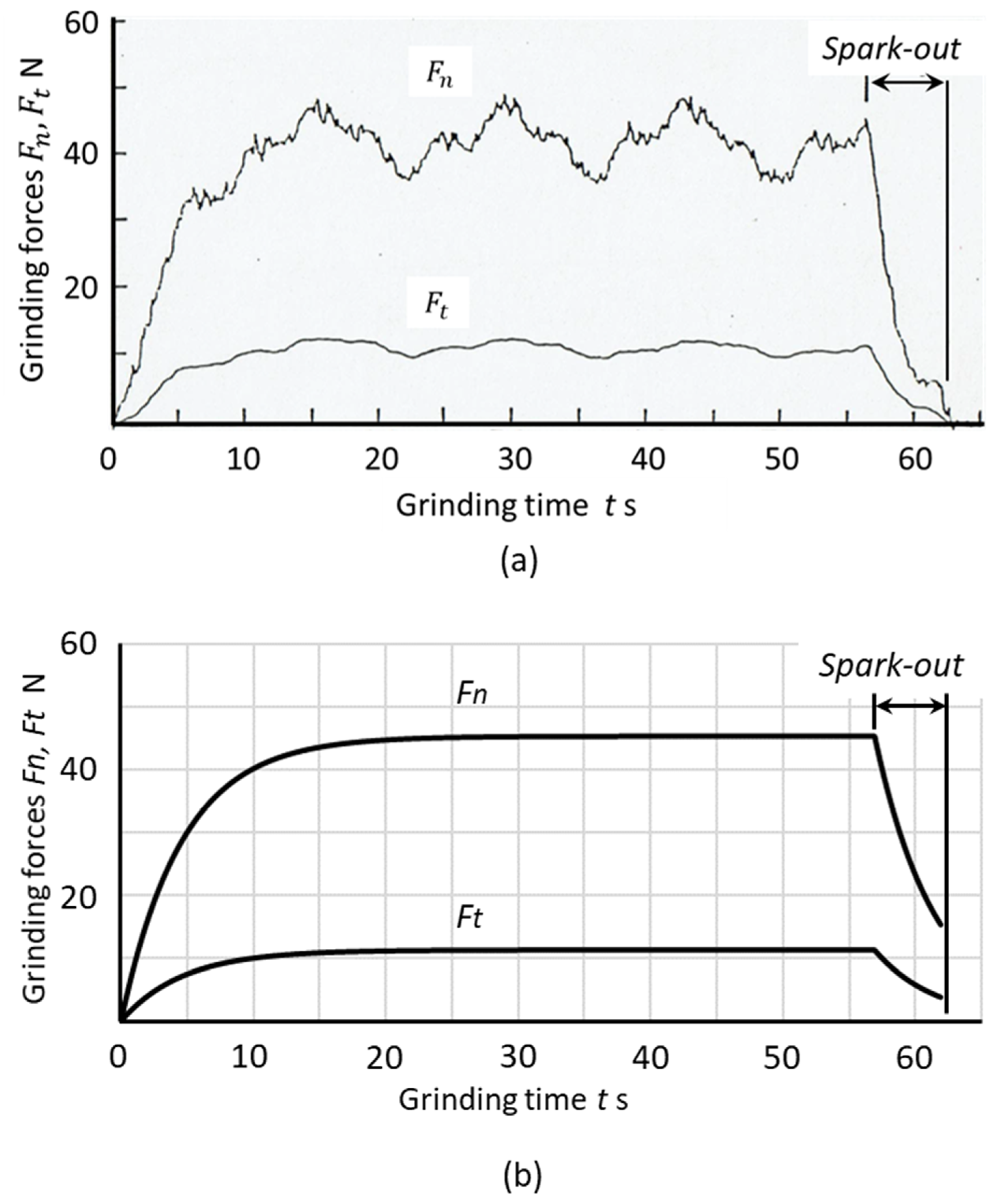
Table 2 delineates the experimental conditions and parameters for the infeed centerless grinding tests (c = 0.5) using workpieces made of soda-lime glass. The regulating wheel spindle of applied centerless grinding machine was supported by hydrostatic bearings. Both the normal and tangential grinding forces were measured by monitoring the pocket pressures of the bearings [26]. A grinding wheel with SiC grains lapped with a carbide chip was applied for the infeed centerless grinding of the glass cylinders. The ground cylinders were visually transparent with no macro-cracks on the ground surface [27]. The grinding time Tg was set to 57 s (including a spark-out time of 5 s).
Figure 21a is a graph of the normal force Fn and tangential force Ft measurement results found during infeed centerless grinding. From the results, the time constant T = 4.6 s was obtained, and an extremely high specific energy of u = 741 J/mm3 was measured due to the ductile grinding of the brittle materials. It is noted that the fluctuations observed on Fn and Ft curves were due to the runout of regulating wheel rotation and truing errors. Figure 21b graphs the infeed centerless grinding simulation results for the same glass cylinder workpieces. The raising transients of the forces were well simulated and the levels of the forces were almost identical. The spark-out behavior was also well simulated.
The results for both chuck type cylindrical grinding and centerless grinding indicate that the presented model can provide accurate predictions of the transient behaviors and the steady-state values of infeed grinding processes.
7. Conclusions
This paper treated infeed cylindrical grinding as a system composed of the grinding mechanism and the grinding machine characteristics. The causalities between the grinding parameters and the machine structures were discussed, and the infeed grinding processes were analyzed as output responses to the operational input from the grinding machine. These relationships were integrated into a block diagram with closed-loop feedback. A novel grinding model exhibiting practical parameters such as work sizes, grinding speed, infeed rate and MRR was presented.
The grinding system analysis derived a factor referred to as “grinding time constant” that governs the transient behaviors of process parameters such as forces and machine deflection. The process parameters used during the infeed cycle (including spark-out grinding) were investigated and the formulas required for the cycle design were presented.
Furthermore, to improve accuracy and productivity, the features of the cycle design were described and the procedures for controlling size error and roundness were developed. Finally, the model was verified by infeed grinding tests applied to both the chuck type cylindrical grinding and centerless grinding methods.
The study produced the following conclusions and results:
- (1)
- In infeed cylindrical grinding, including the centerless methods, the causalities between the grinding fundamentals and the machine characteristics can be clarified, and from that a model of a new system represented by a block diagram with closed-loop feedback can be proposed.
- (2)
- From the characteristic equations of the proposed grinding system, a factor called the “grinding time constant” was revealed. This time constant was found to play a critical role in the infeed process and in spark-out grinding.
- (3)
- Formulas presenting process parameters such as grinding forces and machine deflection were derived, and the procedures for the grinding cycle design were created.
- (4)
- Practical exercises for improving size error, roundness and cycle time in infeed cylindrical grinding were developed and described.
- (5)
- The model was verified by performing grinding tests on both the cylindrical and centerless grinding methods.
Funding
This research received no external funding.
Conflicts of Interest
The authors declare no conflict of interest. F.H. is a founder of Advanced Finishing Company Ltd., in which he holds shares. The sponsors had no role in the design, collection, analysis, or interpretation of data, the writing of this article, or the decision to submit it for publication.
Nomenclature
| s | Laplace operator | T | Grinding time constant |
| Deflection of machine in s-domain | Grinding time | ||
| Rounding error in s-domain | Infeed grinding time | ||
| Actual infeed rate in s-domain | Spark-out time | ||
| Normal grinding force in s-domain | UV | Energy-grinding speed function | |
| Dynamic compliance in s-domain | WP | Workpiece | |
| (s) | Command infeed in s-domain | b | Width of workpiece |
| SMRR in s-domain | c | Grinding method parameter | |
| Actual infeed in s-domain | Deflection of grinding machine | ||
| Depth of cut in s-domain | Diameter of workpiece | ||
| C | Constant | Actual infeed rate | |
| Normal grinding force | Equivalent chip thickness | ||
| Tangential grinding force | Contact stiffness of grinding wheel | ||
| ’ | Specific normal grinding force | Stiffness of grinding system | |
| Specific tangential grinding force | Stiffness of wheel support system | ||
| GW | Grinding wheel | Stiffness of work support system | |
| Command infeed | Stiffness of workpiece itself | ||
| Step infeed in slide position | Rotational speed of workpiece | ||
| Constant infeed rate | Actual infeed | ||
| Km | Static stiffness | t | time |
| Kw | Grinding stiffness | u | Specific energy |
| MRR | Material removal rate | Grinding speed | |
| PS | Percentages of stock assignment | Contact deflection of grinding wheel | |
| Grinding power | Deflection of wheel support system | ||
| Material removal rate | Deflection of work itself | ||
| Specific material removal rate | Deflection of work support system | ||
| RW | Regulating wheel | Δ | Depth of cut per revolution |
| S | Grinding stocks in diameter | η | Force ratio (Fn/Ft) |
| SMRR | Specific material removal rate |
Appendix A
The actual infeed is (see Equation (9)):
where . The machine deflection is expressed by (see Equation (15)):
Therefore,
After differentiating both sides of Equation (A3):
. Therefore,
Take the separation of variables in Equation (A5); then take the integral of both sides.
Therefore,
where C is a constant. Equation (A7) can be rewritten as:
From Equation (A2), at Therefore,
Appendix B
The ramp-infeed is (see Equation (29)):
The deflection of the grinding machine is (see Equation (15)):
Therefore,
After differentiating both sides of Equation (A12):
Then rewrite Equation (A13):
The solution of the first-order linear differential Equation can be expressed by:
Therefore,
given that . Therefore,
References
- Farago, F.T. Abrasive Methods Engineering; Industrial Press: New York, NY, USA, 1980; Volume 1, pp. 3–9. [Google Scholar]
- Schlesinger, G. Die Werkzeugmaschinen: Grundlagen, Berechnung, und Konstruktion; The Machine Tool Industry: Fundamentals, Calculation, and Construction; Springer: Berlin/Heidelberg, Germany, 1936. [Google Scholar]
- Snoeys, R.; Peters, J. The Significance of Chip Thickness in Grinding. CIRP Ann. 1974, 23, 227–237. [Google Scholar]
- Brecker, J.N.; Shaw, M.C. Specific Energy in Single Point Grinding. CIRP Ann. 1974, 23, 93–94. [Google Scholar]
- Malkin, S.; Guo, C. Grinding Technology, 2nd ed.; Industrial Press: New York, NY, USA, 2008; pp. 315–368. [Google Scholar]
- Levin, A.I.; Mashnistov, V.M. Optimization of a Plunge Grinding Cycle. Mach. Tool. 1977, 48, 36. [Google Scholar]
- Lezanski, P.; Rafalowicz, J.; Jedrzejewski, J. An Intelligent Monitoring System for Cylindrical Grinding. CIRP Ann. 1993, 42, 393–396. [Google Scholar] [CrossRef]
- Saljé, E.; Hörsemann, W.; Klyk, M. Grinding of Cylindrical Blanks with Controlled Workspeed. CIRP Ann. 1989, 38, 303–306. [Google Scholar] [CrossRef]
- Tönshoff, H.; Peters, J.; Inasaki, I.; Paul, T. Modelling and Simulation of Grinding Processes. CIRP Ann. 1992, 41, 677–688. [Google Scholar] [CrossRef]
- Tönshoff, H.; Friemuth, T.; Becker, J. Process Monitoring in Grinding. CIRP Ann. 2002, 51, 551–571. [Google Scholar] [CrossRef]
- Hashimoto, F. Dynamic Rounding Stability in Through-Feed Centerless Grinding. Inventions 2020, 5, 17. [Google Scholar] [CrossRef]
- Chiu, N.; Malkin, S. Computer Simulation for Cylindrical Plunge Grinding. CIRP Ann. 1993, 42, 383–387. [Google Scholar] [CrossRef]
- Rowe, W.B.; Miyashita, M.; Koenig, W. Keynote Paper–Centerless Grinding Research and Its Application in Advanced Manufacturing Technology. CIRP Ann. 1989, 38, 1–9. [Google Scholar] [CrossRef]
- Hashimoto, F.; Gallego, I.; Oliveira, J.F.G.; Barrenetxea, D.; Takahashi, M.; Sakakibara, K.; Stålfelt, H.-O.; Staadt, G.; Ogawa, K. Advances in centerless grinding technology. CIRP Ann. 2012, 61, 747–770. [Google Scholar] [CrossRef]
- Altintas, Y.; Brecher, C.; Weck, M.; Witt, S. Virtual Machine Tool. CIRP Ann. 2005, 54, 115–138. [Google Scholar] [CrossRef]
- Brecher, C.; Esser, M.; Witt, S. Interaction of manufacturing process and machine tool. CIRP Ann. 2009, 58, 588–607. [Google Scholar] [CrossRef]
- Tobias, S. Machine tool vibration research. Int. J. Mach. Tool Des. Res. 1961, 1, 1–14. [Google Scholar] [CrossRef]
- Moriwaki, T. Multi-Functional Machine Tool. CIRP Ann. 2008, 57, 736–749. [Google Scholar] [CrossRef]
- Wegener, K.; Bleicher, F.; Krajnik, P.; Hoffmeister, H.-W.; Brecher, C. Recent developments in grinding machines. CIRP Ann. 2017, 66, 779–802. [Google Scholar] [CrossRef]
- Altintaş, Y.; Kersting, P.; Biermann, D.; Budak, E.; Denkena, B.; Lazoglu, I. Virtual process systems for part machining operations. CIRP Ann. 2014, 63, 585–605. [Google Scholar] [CrossRef]
- Hahn, R.S. On the Theory of Regenerative Chatter in Precision Grinding Operations. Trans. ASME 1954, 76, 563. [Google Scholar]
- Snoeys, R.; Brown, D. Dominating Parameters in Grinding Wheel—and Workpiece Regenerative Chatter. In Proceedings of the Tenth International Machine Tool Design and Research Conference, MTDR; University of Manchester Institute of Science and Technology: Manchester, UK, 1969; pp. 325–348. [Google Scholar]
- Inasaki, I.; Karpuschewki, B.; Lee, H.S. Grinding Chatter–Origin and Suppression. CIRP Ann. 2001, 50, 515. [Google Scholar] [CrossRef]
- Brinksmeier, E.; Aurich, J.C.; Govekar, E.; Heinzel, C.; Hoffmeister, H.-W.; Klocke, F.; Peters, J.; Rentsch, R.; Stephenson, D.; Uhlmann, E.; et al. Advances in Modeling and Simulation of Grinding Processes. CIRP Ann. 2006, 55, 667–696. [Google Scholar] [CrossRef]
- Hashimoto, F. Model Development for Optimum Setup Conditions that Satisfy Three Stability Criteria of Centerless Grinding Systems. Inventions 2017, 2, 26. [Google Scholar] [CrossRef]
- Hashimoto, F.; Kanai, A. High Precision Trueing Method of Regulating Wheel and Effect on Grinding Accuracy. CIRP Ann. 1983, 32, 237–239. [Google Scholar] [CrossRef]
- Yoshioka, J.; Hashimoto, F.; Miyashita, M.; Daitoh, M. High-Precision Centerless Grinding of Glass as Preceding Operation to Polishing-Dressing Conditions and Grinding Accuracy. In Proceedings of the International Grinding Conference, Fontana, WI, USA, 27–29 August 1984; SME84-542. pp. 1–13. [Google Scholar]
Figure 1.
Generalized grinding model.

Figure 2.
Dynamic grinding model for roundness stability criterion.

Figure 3.
Static grinding model for practical grinding operations.

Figure 4.
Cylindrical grinding methods (WP: workpiece, GW: grinding wheel, RW: regulating wheel). (a) Center-chuck type grinding c = 1.0; (b) Centerless grinding c = 0.5; (c) Shoe centerless grinding c = 0.5.
Figure 4.
Cylindrical grinding methods (WP: workpiece, GW: grinding wheel, RW: regulating wheel). (a) Center-chuck type grinding c = 1.0; (b) Centerless grinding c = 0.5; (c) Shoe centerless grinding c = 0.5.

Figure 5.
Equivalent chip thickness vs. grinding force in cylindrical grinding.

Figure 6.
Machine stiffness in a grinding system. (a) Grinding wheel support system; (b) Work head support system; (c) Workpiece stiffness; (d) Contact stiffness of grinding wheel.
Figure 6.
Machine stiffness in a grinding system. (a) Grinding wheel support system; (b) Work head support system; (c) Workpiece stiffness; (d) Contact stiffness of grinding wheel.

Figure 7.
Schematic of cylindrical grinding machine.

Figure 8.
Block diagram of cylindrical grinding system.

Figure 9.
Responses to step infeed in cylindrical infeed grinding (spark-out grinding). (a) Actual infeed I0 = 5 μm; (b) Normal grinding force Fn(0) = 99.8 N; (c) Machine deflection de (0) = 5 μm.
Figure 9.
Responses to step infeed in cylindrical infeed grinding (spark-out grinding). (a) Actual infeed I0 = 5 μm; (b) Normal grinding force Fn(0) = 99.8 N; (c) Machine deflection de (0) = 5 μm.

Figure 10.
Responses to ramp infeed in cylindrical infeed grinding (plunge grinding). (a) Actual infeed; (b) Normal grinding force; (c) Machine deflection.
Figure 10.
Responses to ramp infeed in cylindrical infeed grinding (plunge grinding). (a) Actual infeed; (b) Normal grinding force; (c) Machine deflection.

Figure 11.
Effect of time constant on infeed grinding processes. (a) Slide position; (b) Forces, power and machine deflection; (c) Spark-out in forces, power and deflection.
Figure 11.
Effect of time constant on infeed grinding processes. (a) Slide position; (b) Forces, power and machine deflection; (c) Spark-out in forces, power and deflection.

Figure 12.
System stiffness and time constant.

Figure 13.
Diagram for infeed grinding cycle.

Figure 14.
Setup of infeed grinding cycle.

Figure 15.
Process parameters during the infeed grinding cycle. (a) Infeed rate; (b) Command and actual slide position; (c) Normal grinding force; (d) Deflection of grinding machine.
Figure 15.
Process parameters during the infeed grinding cycle. (a) Infeed rate; (b) Command and actual slide position; (c) Normal grinding force; (d) Deflection of grinding machine.

Figure 16.
Influences of the time constant on the behaviors of process parameters. (a) Actual infeed position; (b) Deflection of grinding machine.
Figure 16.
Influences of the time constant on the behaviors of process parameters. (a) Actual infeed position; (b) Deflection of grinding machine.

Figure 17.
Primary grinding cycle.

Figure 18.
Roundness error caused by the residual depth of cut. (a) Work rotation during infeed grinding; (b) Step-roundness.
Figure 18.
Roundness error caused by the residual depth of cut. (a) Work rotation during infeed grinding; (b) Step-roundness.

Figure 19.
SMRR (Specific Material Removal Rate) and stock assignments.

Figure 20.
Test results and simulation for infeed cylindrical grinding. (a) Power of infeed cylindrical grinding (Experimental); (b) Simulation of infeed cylindrical grinding (Theoretical).
Figure 20.
Test results and simulation for infeed cylindrical grinding. (a) Power of infeed cylindrical grinding (Experimental); (b) Simulation of infeed cylindrical grinding (Theoretical).

Figure 21.
Grinding test results and simulation for infeed centerless grinding. (a) Test results of infeed centerless grinding of glass; (b) Simulation results of infeed centerless grinding.
Figure 21.
Grinding test results and simulation for infeed centerless grinding. (a) Test results of infeed centerless grinding of glass; (b) Simulation results of infeed centerless grinding.


Table 1.
Experimental setup in infeed cylindrical grinding.
| Items | Conditions |
|---|---|
| Grinding machine | Universal cylindrical grinder |
| Grinding method | Chuck type cylindrical grinding c = 1.0 |
| Workpiece | Thru-hardened steel HRC58 Diameter dw= 177.8 mm, width b = 30 mm |
| Grinding wheel | Al2O3 70 K m V Diameter ds = 127 mm, width Ls = 86.4 mm Grinding speed vs = 45 m/s |
| Stocks in diameter | S = 0.33 mm |
| SMRR (Specific Material Removal Rate) | Qw’ = 2.0 mm3/(mm·s) |
| Infeed rate | fi = 0.216 mm/min |
| Spark-out time | Tsp = 5.3 s |
| Grinding time | Tg = 51.1 s |
| Specific energy | u = 26.7 J/mm3 |
| Force ratio (Fn/Ft) | η = 2.0 |
| System stiffness | km = 2421 N/mm |
| Time constant | T = 8.2 s |
Table 2.
Experimental setup in infeed centerless grinding.
| Items | Conditions |
|---|---|
| Grinding machine | Centerless grinder |
| Grinding method | Infeed centerless grinding c = 0.5 |
| Workpiece | Soda-lime glass, HV500 Diameter dw = 12.4 mm, width b = 66 mm |
| Grinding wheel | SiC, GC 100 L m V Diameter ds = 455 mm, width Ls = 150 mm Grinding speed vs = 29 m/s |
| Regulating wheel | A 150 R R Diameter dr = 255 mm, width Ls = 150 mm Rotational speed Nr = 24.4 rpm |
| Stocks in diameter | S = 0.1 mm |
| SMRR (Specific Material Removal Rate) | Qw’ = 0.0325 mm3/(mm·s) |
| Infeed rate | fi = 0.10 mm/min |
| Spark-out time | Tsp = 5.0 s |
| Grinding time | Tg = 57 s |
| Specific energy | u = 741 J/mm3 |
| Force ratio (Fn/Ft) | η = 4.0 |
| System stiffness | km = 5900 N/mm |
| Time constant | T = 4.6 s |
© 2020 by the author. Licensee MDPI, Basel, Switzerland. This article is an open access article distributed under the terms and conditions of the Creative Commons Attribution (CC BY) license (http://creativecommons.org/licenses/by/4.0/).
Share and Cite
MDPI and ACS Style
Hashimoto, F. The Design of an Infeed Cylindrical Grinding Cycle. Inventions 2020, 5, 46. https://doi.org/10.3390/inventions5030046
AMA Style
Hashimoto F. The Design of an Infeed Cylindrical Grinding Cycle. Inventions. 2020; 5(3):46. https://doi.org/10.3390/inventions5030046
Chicago/Turabian StyleHashimoto, Fukuo. 2020. "The Design of an Infeed Cylindrical Grinding Cycle" Inventions 5, no. 3: 46. https://doi.org/10.3390/inventions5030046