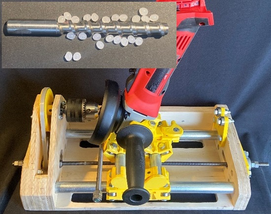
Open-Source Grinding Machine for Compression Screw Manufacturing


Abstract
:
1. Introduction
2. Materials and Methods
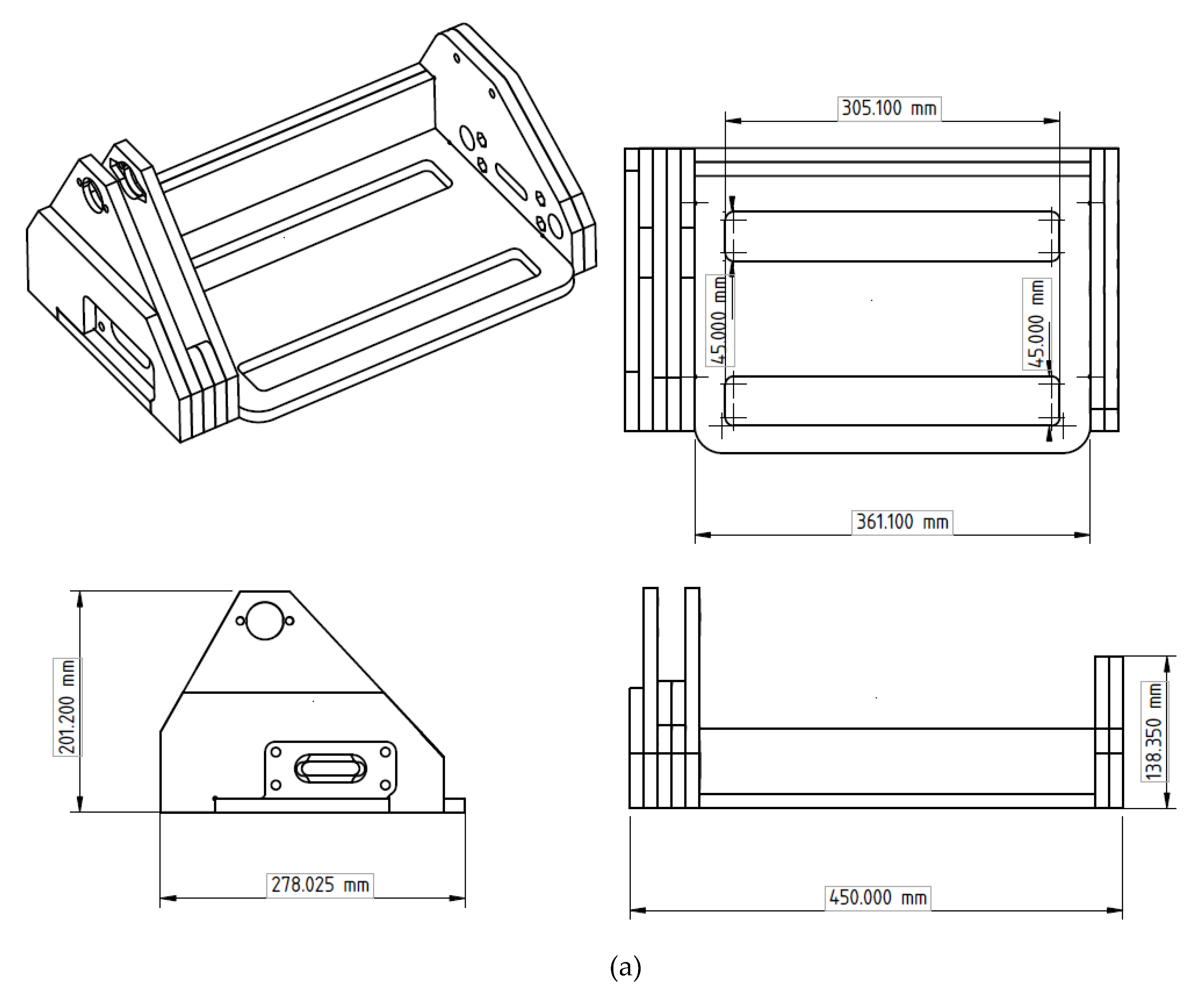
2.1. Design
Manufacturing
2.2. Assembly
- a
- In all three sliders, bolt in the 608ZZ bearing with M8 bolts and a lock nut shown in Figure 2.
- b
- On the Y-axis slider, install:
- Tool quick-release mounting hardware,
- Probe mount, and
- Threaded rod with the pointed end into the probe mount.
- c
- On the X sliders install:
- Y-axis tube lower mount, and
- Threaded rod coupler to connect the two X sliders.
- d
- On the angle grinder install:
- Required tool mounting hardware which will vary based on what model angle grinder is being used.
- e
- On the free-end support, attach two bearings to the top holes and one to the top clamp with an M8 bolt and lock nut. The top clamp should be mounted on the same M8 bolt that secures the two lower bearings.
- f
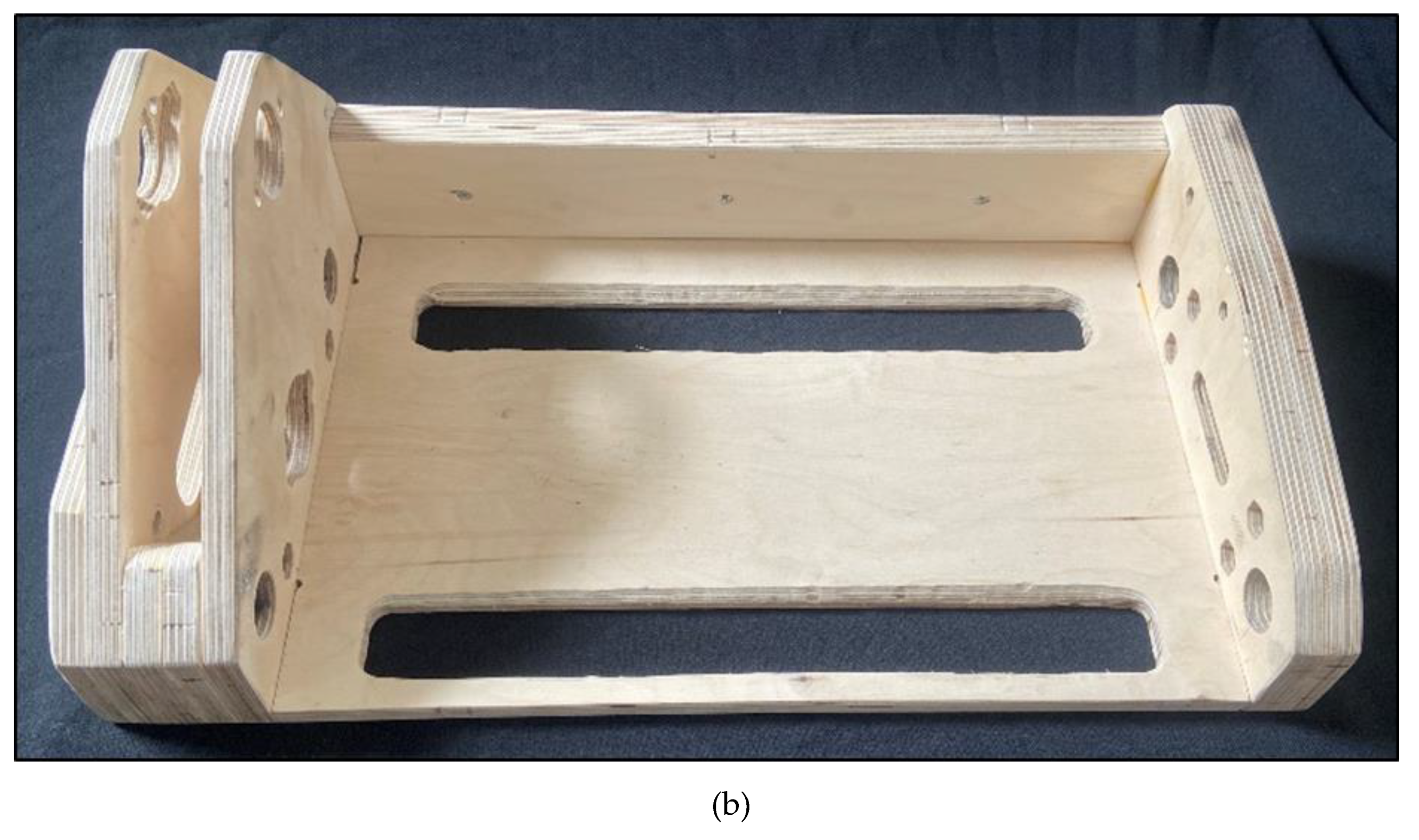
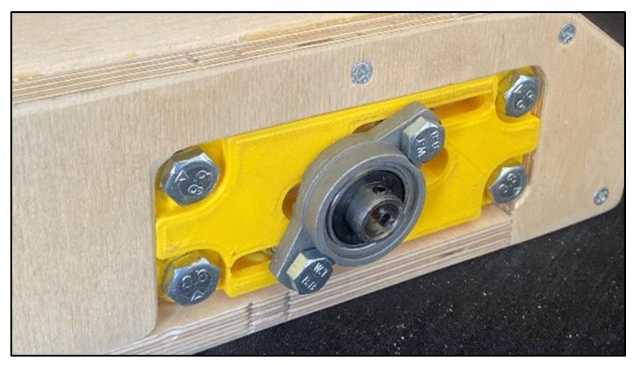
- Attach 1 flange pillow block bearing on each threaded rod tension slide, leaving it loose enough to slide the bearing.
- g
- On both pulleys, insert M3 nuts and start M3 × 12 mm bolts into the nuts.
- h
- Using M3 hardware, connect the desired profile to the profile mount.
- a
- X-axis assembly.
- Insert X-axis tube through the open holes on the end-cap subassembly.
- b
- Push the X sliders onto the tube and insert the tube all the way into the chuck-end assembly until it reaches the backing board C5.
- c
- Install the drill chuck assembly with the desired chuck side pulley mounted onto the shaft of the chuck.
- Make sure the belt is looped around the chuck shaft.
- d
- Install the threaded rod tension slide on both ends with M8 bolts and M8 lock nuts, as shown in Figure 3.
- e
- Threaded rod installation
- Insert the threaded rod through the free-end side pillow block bearing and move it up to the X slider. Insert a hex nut on each side and a spring in the middle to reduce backlash. Screw the threaded rod onto both nuts. Continue rotating the rod, moving it closer to the front of the chuck assembly. Screw on a pair of hex nuts, lower pulley, and then add another pair of hex nuts. Push the threaded rod through the other pillow block bearing and check that the pulley is lined up with the pulley attached to the chuck. Tighten the nuts on both sides of the pulley and tighten the M3 bolts on the pulley itself to secure it in place. Reinsert the threaded rod through the pillow block bearing and secure a pair of hex nuts on both ends of the threaded rod to help keep the threaded rod from moving. Install the belt on both pulleys, slide the threaded rod equally on both sides, and tighten the pillow block bearings.
- f
- Installing the Y-axis subassembly
- Slide on the Y slider onto the Y-axis tubes.
- Insert the Y-axis tubes and secure with the 3D-printed tube clamp.
- g
- Install the free-end support, leaving it loose enough to be able to adjust it when adding round stock.
- h
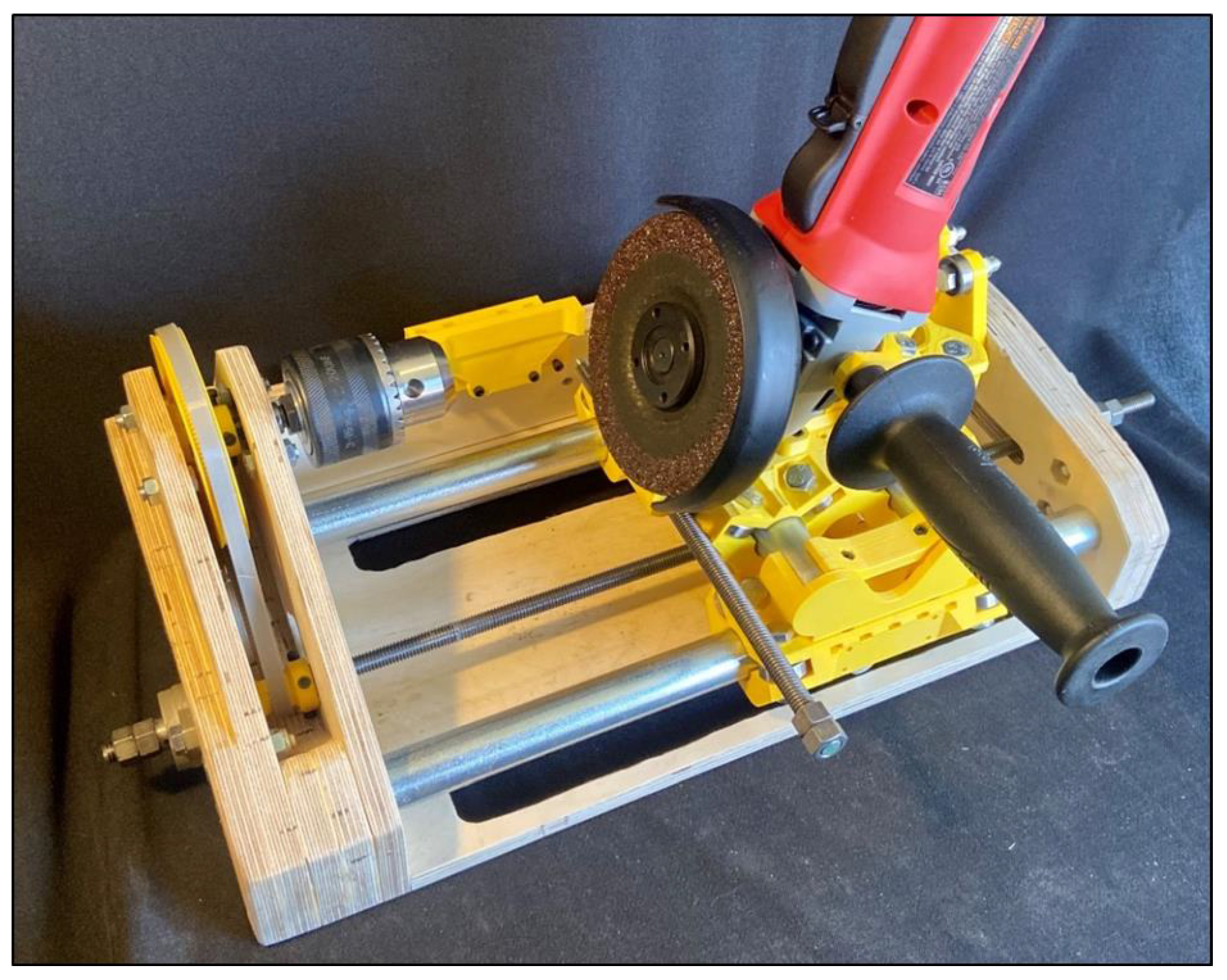
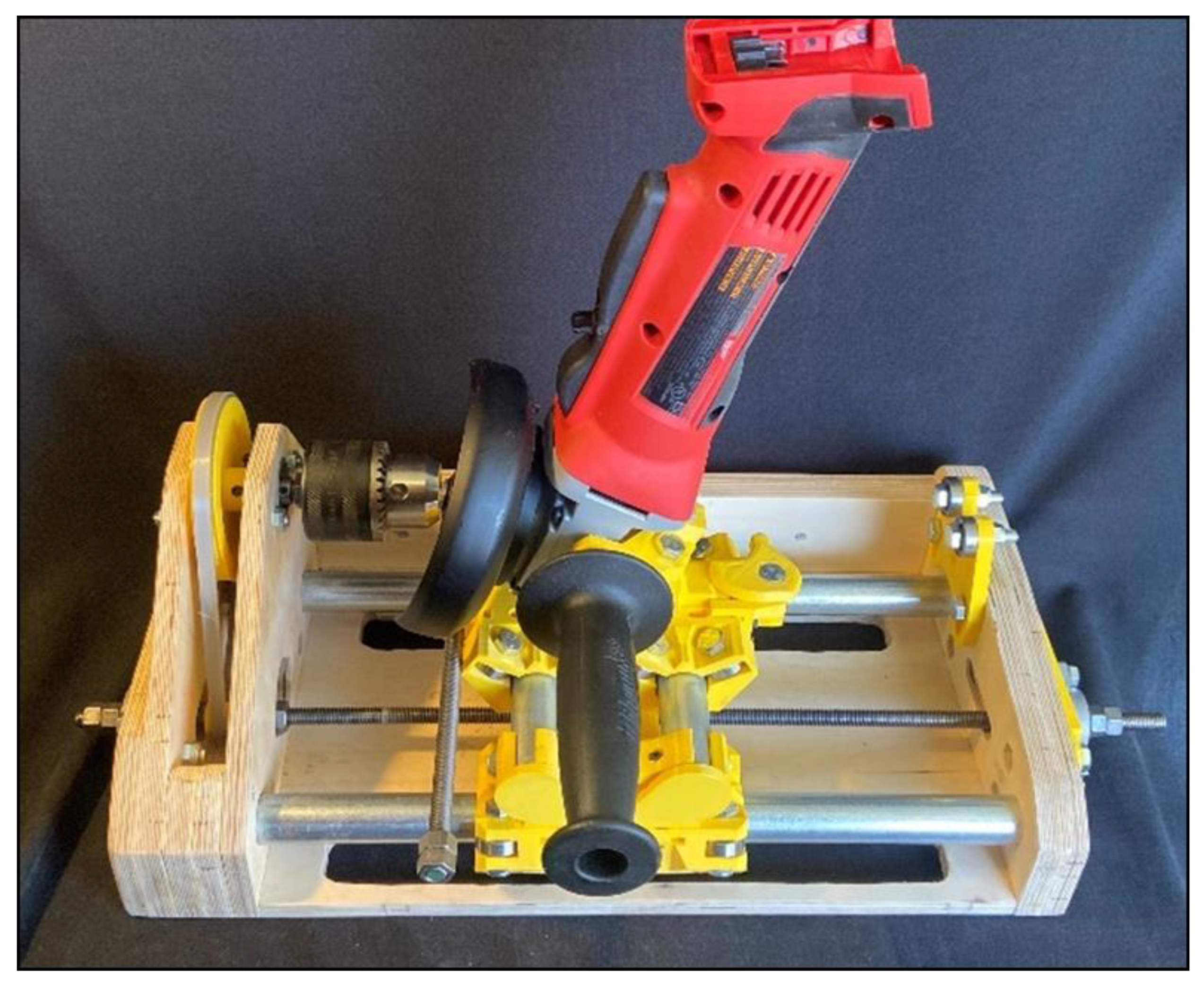
- Install angle grinder with appropriate grinding disk onto the Y slider.
- i
- Install the profile mount onto the back cross-section and adjust to align with the cutter disk and the round stock.
2.3. Operation
2.3.1. Machine Operation
- Install desired round stock.
- Check that a proper abrasive grinding disk is installed on the angle grinder for the material being cut.
- a
- It is economically advantageous to employ a more heavily used grinding disk for roughing passes and a new disk for finishing passes.
- To move the tool, rotate the threaded rod. The direction of rotation is dependent on the handedness of the threaded rod used.
- Rotation can be achieved by attaching a drill onto the hex nuts at the end of the threaded rod. Alternatively, if a drill is unavailable, a ratchet wrench, or a 3D-printed crank could be used to rotate the threaded rod. While operating by hand is possible, it will take much longer to move the tool along the X-axis.
- For the initial operation cycle, the grinder motion in both axes must be checked to ensure the grinder is able to move freely.
- Setting the angle grinder to the Y-axis position:
- Align the angle grinder with the round stock that is installed in the chuck at the starting point.
- Move the profile mount to where the starting point on the profile is aligned with the probe.
- Move the probe such that it is in contact with the pad to the left of the starting point.
- It is important that the profile is designed for the diameter of the round stock. Using a profile designed for 10 mm round stock on 8 mm round stock could result in cutting through the round stock depending on the profile.
- Once the probe is set, run the grinder while the machine is off down the length of the round stock to check that it is just contacting the round stock.
- At this point, return the grinder to the starting point for the shaping process.
- Make a shallow first cut that should only be approximately 0.5 mm in depth.
- Once at the end of the screw, return the grinder back to the start.
- The grinder can remain on or off.
- Make several passes, removing approximately 1 mm of material in each pass.
- Repeat until the probe is in contact with the profile for the entire pass.
- Once the screw has been cut, it is now time to move onto finishing the finishing steps. Finish the screw by sanding down the burrs and polishing.
2.3.2. Machine Performance Requirements
2.4. Validation Tests
- Machine characterization for costs, screw section length cut, diameter rod range, and battery-life test for grinding screws 110 mm in length.
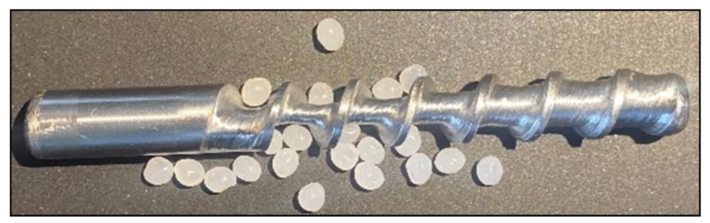
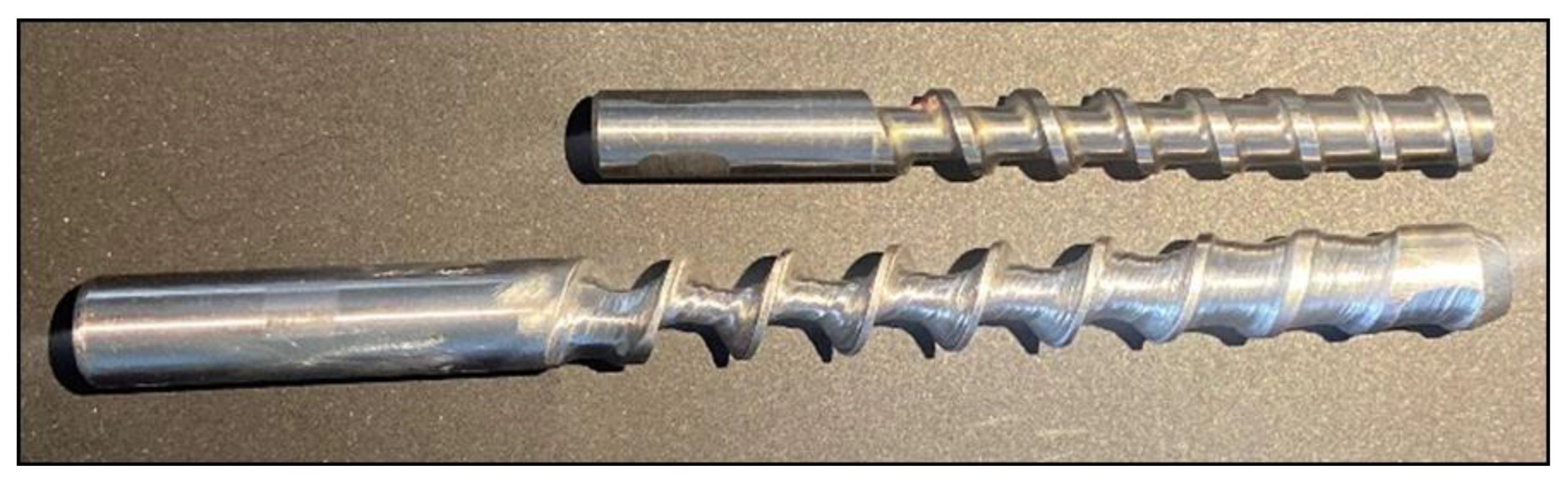
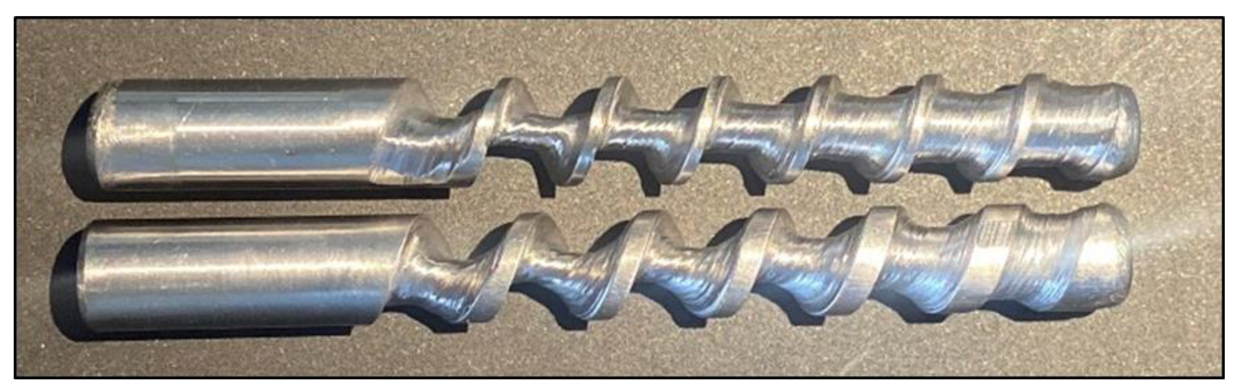
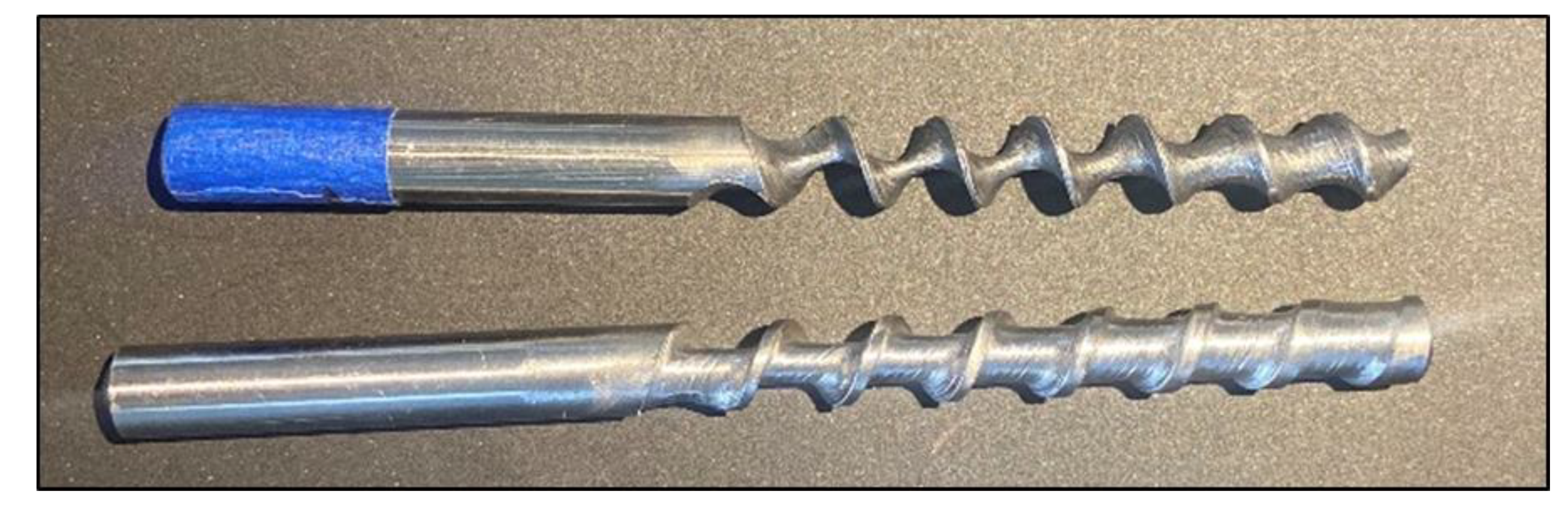
- Demonstration of screw cutting with variation in (i) channel depth, (ii) screw diameter, (iii) screw length, (iv) change in pitch, (v) abrasive disk thickness, (vi) the handedness of the threaded rod, (vii) and various materials including 1045 steel, 1144 steel, and 416 stainless steel.
3. Results
3.1. Machine Characterization
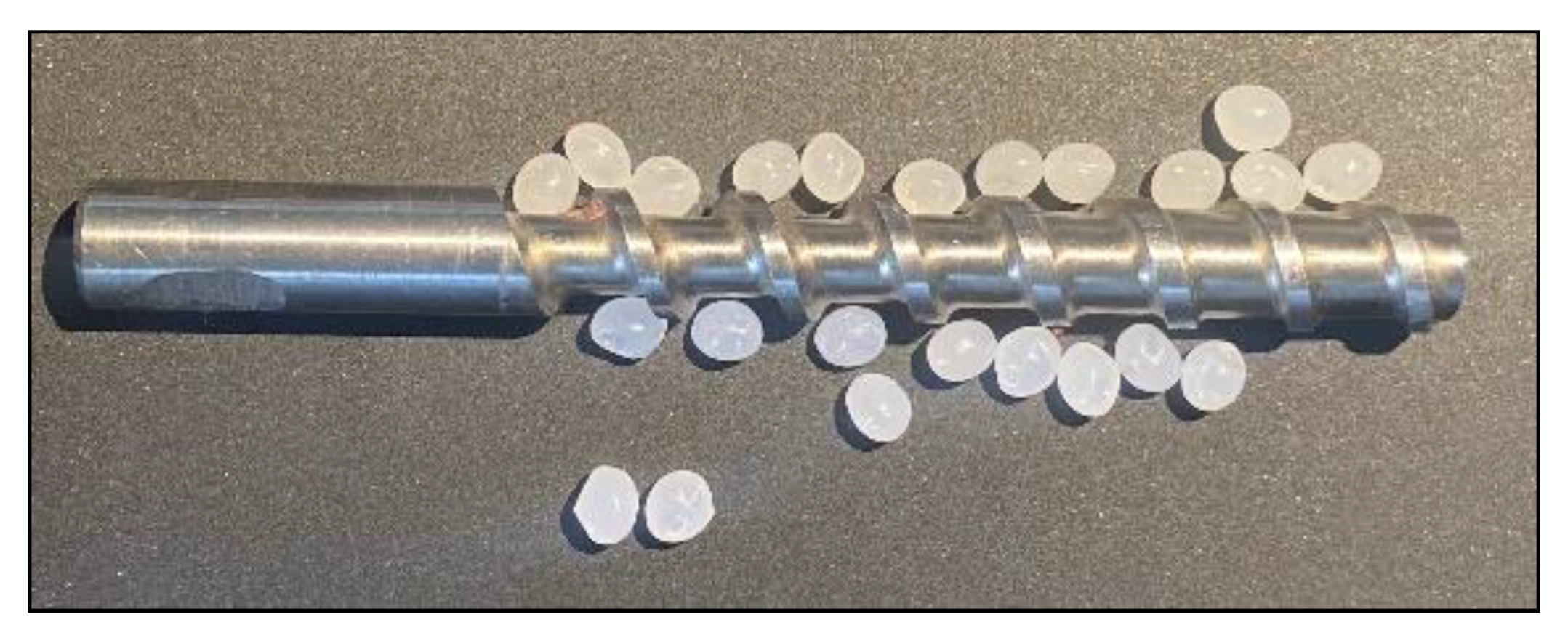
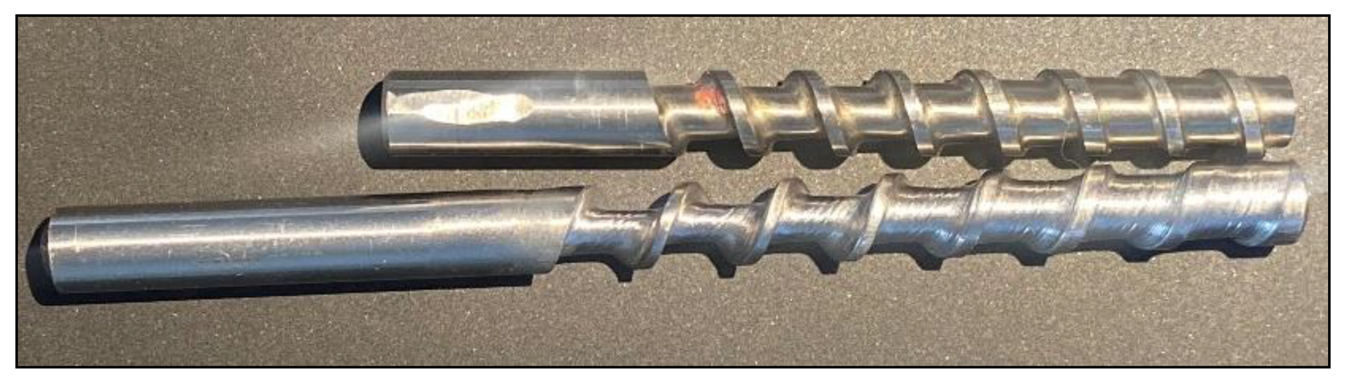
3.2. Machined Compression Screws
4. Discussion
Machine Limitations
5. Conclusions
Supplementary Materials
Author Contributions
Funding
Conflicts of Interest
Appendix A. Manufactured Components

| Name | Quantity | Description | Mater-ial | Manufacturing Methods/Settings | |
|---|---|---|---|---|---|
| X-Axis Slider |  | 2 | Used for linear motion platform for the X-axis | PLA | 3D Printed
|
| Y-Axis Slider |  | 1 | Used for linear motion platform for the Y-axis | PLA | 3D Printed
|
| Y-axis Tube Lower Mount |  | 2 | Mounting the pipes used for the Y-axis | PLA | 3D Printed
|
| Y-Axis Tube Top Clamp |  | 2 | Securing the Y-axis pipes | PLA | 3D Printed
|
| Threaded Rod Tension Slide |  | 2 | Mounting the pillow block flange bearings that hold the threaded rod | PLA | 3D Printed
|
| Threaded Rod Coupler |  | 2 | Used to connect the X-axis sliders and holds the two nuts and spring that are installed on the threaded rod | PLA | 3D Printed
|
| Probe Mount |  | 1 | Holds threaded rod with a pointed end that is used to follow the profile part | PLA | 3D Printed
|
| Grinder Mount Angle |  | 1 | Positions the angle grinder to match the helix angle of the screw being machined. Attached to Y-axis slider with the quick-release lockdown | PLA | 3D Printed
|
| M18 Bracket |  | 1 | This bracket is mounted onto the Milwaukee 2680 angle grinder. Other models might require a different bracket to be designed | PLA | 3D Printed
|
| Quick-Release Bridge Clamp |  | 1 | Part of the quick-release lockdown system to secure the angle grinder mount | PLA | 3D Printed
|
| Quick-Release Lockdown Lever |  | 1 | Lever to secure the angle grinder tool mount | PLA | 3D Printed
|
| Lock-Side Grinder Mount |  | 1 | Bracket that holds the quick-release lockdown lever | PLA | 3D Printed
|
| Profile Mount |  | 1 | Mounts onto cross-brace to secure two different profiles for machining | PLA | 3D Printed
|
| Profile |  | 1 * | The probe on the Y-axis slider moves across the face of the profile to control the channel depth of the screw during grinding | PLA | 3D Printed
|
| Belt |  | 1 * | Belt to connect the chuck and threaded rod pulleys | Nijatek Ninjaflex 85 A | 3D Printed
|
| Chuck Pulley |  | 1 * | Mounted on the chuck shaft that controls the pitch of the screw | PLA | 3D Printed
|
| Threaded Rod Pulley |  | 1 * | Mounted on the threaded rod to control the pitch of the screw | PLA | 3D Printed
|
| Base |  | 1 | Base of the plywood frame | ½″ Baltic birch plywood | Multiple methods
|
| C1 |  | 1 | Chuck-end component | ½″ Baltic birch plywood | Multiple methods
|
| C2 and C3 |  | 1 | Chuck-end component | ½″ Baltic birch plywood | Multiple methods
|
| C4 |  | 1 | Chuck-end component | ½″ Baltic birch plywood | Multiple methods
|
| C5 |  | 1 | Chuck-end component | ½″ Baltic birch plywood | Multiple methods
|
| Cross-Brace |  | 1 | Connects the chuck-end subassembly and the free-end subassembly | ½″ Baltic birch plywood | Multiple methods
|
| F1 |  | 1 | Free-end component | ½″ Baltic birch plywood | Multiple methods
|
| F2 |  | 1 | Free-end component | ½″ Baltic birch plywood | Multiple methods
|
Appendix B. Operation Details of Open-Source Grinder

| Task Number | Name of Operation | Description of Task | Estimated Time (minutes) | Notes |
|---|---|---|---|---|
| 1 | Loading stock | Installing stock into chuck and adjusting supports | 5 | Ensure the stock is parallel to the X-axis of the machine |
| 2 | Grinder alignment | Setting the starting depth of the grinder and positioning the profile | 2 | If performing a finishing pass, have the finishing pass disk installed |
| 3 | Roughing disk installation | Install the disk to be used for roughing passes | 1 | |
| 4 | Roughing pass | Start making passes with the grinder removing the bulk of the material | 2 | Make sure not to force the angle grinder hard into the stock, as it may bend the stock material. If the stock is starting to change color, the feed rate is too fast |
| 5 | Finishing disk installation | Install the disk to be used for finishing passes | 1 | This disk needs to have minimum wear |
| 6 | Finishing pass | Removing excess stock not reached by the roughing disk | 1 | Machine screw until the desired geometry is made |
| 7 | Stock removal | Removing screw and excess stock from the machine | 2 | |
| 8 | Cutting screw from stock | Cutting off the screw from the stock material | < 1 | Angle grinder with a thin cut-off disk to be used |
| 9 | Screw finishing | Removal of burrs left from the grinding process and polishing the screw | 10+ | Methods for this section will vary based on tools available |
References
- Fogel, K. Producing Open Source Software: How to Run a Successful Free Software Project; O’Reilly Media, Inc.: Sebastopol, CA, USA, 2005; ISBN 978-0-596-55299-2. [Google Scholar]
- Weber, S. The Success of Open Source; Harvard University Press: Cambridge, MA, USA, 2004; ISBN 978-0-674-01292-9. [Google Scholar]
- Gibb, A. Building Open Source Hardware: DIY Manufacturing for Hackers and Makers; Pearson Education: London, UK, 2014. [Google Scholar]
- Pearce, J.M. Sponsored Libre Research Agreements to Create Free and Open Source Software and Hardware. Inventions 2018, 3, 44. [Google Scholar] [CrossRef] [Green Version]
- Margolis, M. Arduino Cookbook: Recipes to Begin, Expand, and Enhance Your Projects; O’Reilly Media, Inc.: Sebastopol, CA, USA, 2011; ISBN 978-1-4493-2120-8. [Google Scholar]
- Banzi, M.; Shiloh, M. Getting Started with Arduino: The Open Source Electronics Prototyping Platform; Maker Media, Inc.: Sebastopol, CA, USA, 2014; ISBN 978-1-4493-6329-1. [Google Scholar]
- Sells, E.; Bailard, S.; Smith, Z.; Bowyer, A.; Olliver, V. RepRap: The Replicating Rapid Prototyper-Maximizing Customizability by Breeding the Means of Production. In Proceedings of the World Conference on Mass Customization and Personalization, Cambridge, MA, USA, 7–10 October 2007. [Google Scholar]
- Jones, R.; Haufe, P.; Sells, E.; Iravani, P.; Olliver, V.; Palmer, C.; Bowyer, A. RepRap-the Replicating Rapid Prototyper. Robotica 2011, 29, 177–191. [Google Scholar] [CrossRef] [Green Version]
- Bowyer, A. 3D Printing and Humanity’s First Imperfect Replicator. 3D Print. Addit. Manuf. 2014, 1, 4–5. [Google Scholar] [CrossRef]
- Rundle, G. A Revolution in the Making: 3D Printing. In Robots and the Future; Affirm Press: South Melbourne, Australia, 2014. [Google Scholar]
- Campbell, I.; Diegel, O.; Kowen, J.; Wohlers, T. Wohlers Report 2018: 3D Printing and Additive Manufacturing State of the Industry: Annual Worldwide Progress Report; Wohlers Associates: Fort Collins, CO, USA, 2018; ISBN 978-0-9913332-4-0. [Google Scholar]
- Gwamuri, J.; Wittbrodt, B.; Anzalone, N.; Pearce, J. Reversing the Trend of Large Scale and Centralization in Manufacturing: The Case of Distributed Manufacturing of Customizable 3D-Printable Self-Adjustable Glasses. Chall. Sustain. 2014, 2, 30–40. [Google Scholar] [CrossRef]
- Steenhuis, H.J.; Pretorius, L. Consumer additive manufacturing or 3D printing adoption: An exploratory study. J. Manuf. Technol. Manag. 2016, 27, 990–1012. [Google Scholar] [CrossRef]
- Wittbrodt, B.; Laureto, J.; Tymrak, B.; Pearce, J. Distributed Manufacturing with 3D Printing: A Case Study of Recreational Vehicle Solar Photovoltaic Mounting Systems. J. Frugal Innov. 2015, 1, 1–7. [Google Scholar] [CrossRef] [Green Version]
- Woern, A.L.; Pearce, J.M. Distributed Manufacturing of Flexible Products: Technical Feasibility and Economic Viability. Technologies 2017, 5, 71. [Google Scholar] [CrossRef] [Green Version]
- Wittbrodt, B.T.; Glover, A.G.; Laureto, J.; Anzalone, G.C.; Oppliger, D.; Irwin, J.L.; Pearce, J.M. Life-cycle economic analysis of distributed manufacturing with open-source 3D printers. Mechatronics 2013, 23, 713–726. [Google Scholar] [CrossRef] [Green Version]
- Desai, D.R.; Magliocca, G.N. Patents, meet Napster: 3D printing and the digitization of things. Geo. LJ 2013, 102, 1691. [Google Scholar]
- Petersen, E.E.; Pearce, J. Emergence of Home Manufacturing in the Developed World: Return on Investment for Open-Source 3D Printers. Technologies 2017, 5, 7. [Google Scholar] [CrossRef] [Green Version]
- Pearce, J.M. Building research equipment with free, open-source hardware. Science 2012, 337, 1303–1304. [Google Scholar] [CrossRef] [PubMed]
- Pearce, J. Open-Source Lab: How to Build Your Own Hardware and Reduce Research Costs; Elsevier: New York, NY, USA, 2013. [Google Scholar]
- Coakley, M.; Hurt, D.E. 3D Printing in the Laboratory: Maximize Time and Funds with Customized and Open-Source Labware. J. Lab. Autom. 2016, 21, 489–495. [Google Scholar] [CrossRef] [PubMed] [Green Version]
- Baden, T.; Chagas, A.M.; Gage, G.; Marzullo, T.; Prieto-Godino, L.L.; Euler, T. Open Labware: 3-D Printing Your Own Lab Equipment. PLoS Biol. 2015, 13, e1002086. [Google Scholar] [CrossRef] [PubMed]
- Chagas, A.M. Haves and have nots must find a better way: The case for open scientific hardware. PLoS Biol. 2018, 16, e3000014. [Google Scholar] [CrossRef] [Green Version]
- Pearce, J.M. Return on investment for open source scientific hardware development. Sci. Public Policy 2016, 43, 192–195. [Google Scholar] [CrossRef]
- Pearce, J. Quantifying the Value of Open Source Hardware Development. Mod. Econ. 2015, 6, 1–11. [Google Scholar] [CrossRef] [Green Version]
- Moritz, M.; Redlich, T.; Günyar, S.; Winter, L.; Wulfsberg, J.P. On the Economic Value of Open Source Hardware—Case Study of an Open Source Magnetic Resonance Imaging Scanner. J. Open Hardw. 2019, 3, 2. [Google Scholar] [CrossRef]
- Anderson, P.; Sherman, C.A. A discussion of new business models for 3D printing. Int. J. Technol. Mark. 2007, 2, 280–294. [Google Scholar] [CrossRef]
- Doherty, D. Downloading infringement: Patent law as a roadblock to the 3D printing revolution. Harv. JL Tech. 2012, 26, 353. [Google Scholar]
- Berman, B. 3-D printing: The new industrial revolution. Bus. Horiz. 2012, 55, 155–162. [Google Scholar] [CrossRef]
- Laplume, A.; Anzalone, G.; Pearce, J. Open-source, self-replicating 3D printer factory for small-business manufacturing. Int. J. Adv. Manuf. Technol. 2015, 85, 633–642. [Google Scholar] [CrossRef] [Green Version]
- Bogers, M.; Hadar, R.; Bilberg, A. Additive manufacturing for consumer-centric business models: Implications for supply chains in consumer goods manufacturing. Technol. Forecast. Soc. Chang. 2016, 102, 225–239. [Google Scholar] [CrossRef]
- Laplume, A.; Petersen, B.; Pearce, J. Global value chains from a 3D printing perspective. J. Int. Bus. Stud. 2016, 47, 595–609. [Google Scholar] [CrossRef]
- Attaran, M. The rise of 3-D printing: The advantages of additive manufacturing over traditional manufacturing. Bus. Horiz. 2017, 60, 677–688. [Google Scholar] [CrossRef]
- Hoy, M.B. 3D Printing: Making Things at the Library. Med Ref. Serv. Q. 2013, 32, 93–99. [Google Scholar] [CrossRef]
- Fernandez, P. “Through the looking glass: Envisioning new library technologies” the possibilities and challenges of 3-D printing. Libr. Hi Tech News 2014, 31. [Google Scholar] [CrossRef]
- Pryor, S. Implementing a 3D Printing Service in an Academic Library. J. Libr. Adm. 2014, 54, 1–10. [Google Scholar] [CrossRef] [Green Version]
- Rayna, T.; Striukova, L. From rapid prototyping to home fabrication: How 3D printing is changing business model innovation. Technol. Forecast. Soc. Chang. 2016, 102, 214–224. [Google Scholar] [CrossRef] [Green Version]
- Wang, Q.; Sun, X.; Cobb, S.; Lawson, G.; Sharples, S. 3D printing system: An innovation for small-scale manufacturing in home settings?—Early adopters of 3D printing systems in China. Int. J. Prod. Res. 2016, 54, 6017–6032. [Google Scholar] [CrossRef]
- Petersen, E.E.; Kidd, R.W.; Pearce, J.M. Impact of DIY Home Manufacturing with 3D Printing on the Toy and Game Market. Technologies 2017, 5, 45. [Google Scholar] [CrossRef]
- Gallup, N.; Bow, J.K.; Pearce, J.M. Economic Potential for Distributed Manufacturing of Adaptive Aids for Arthritis Patients in the U.S. Geriatrics 2018, 3, 89. [Google Scholar] [CrossRef] [PubMed] [Green Version]
- Baechler, C.; DeVuono, M.; Pearce, J.M. Distributed recycling of waste polymer into RepRap feedstock. Rapid Prototyp. J. 2013, 19, 118–125. [Google Scholar] [CrossRef]
- Woern, A.L.; McCaslin, J.R.; Pringle, A.M.; Pearce, J.M. RepRapable Recyclebot: Open source 3D printable extruder for converting plastic to 3D printing filament. HardwareX 2018, 4, e00026. [Google Scholar] [CrossRef]
- Unruh, G. Circular Economy, 3D Printing, and the Biosphere Rules. Calif. Manag. Rev. 2018, 60, 95–111. [Google Scholar] [CrossRef]
- Zhong, S.; Pearce, J.M. Tightening the loop on the circular economy: Coupled distributed recycling and manufacturing with recyclebot and RepRap 3D printing. Resour. Conserv. Recycl. 2018, 128, 48–58. [Google Scholar] [CrossRef] [Green Version]
- Dertinger, S.C.; Gallup, N.; Tanikella, N.G.; Grasso, M.; Vahid, S.; Foot, P.J.S.; Pearce, J.M. Technical pathways for distributed recycling of polymer composites for distributed manufacturing: Windshield wiper blades. Resour. Conserv. Recycl. 2020, 157, 104810. [Google Scholar] [CrossRef]
- Cruz Sanchez, F.A.; Boudaoud, H.; Camargo, M.; Pearce, J.M. Plastic recycling in additive manufacturing: A systematic literature review and opportunities for the circular economy. J. Clean. Prod. 2020, 264, 121602. [Google Scholar] [CrossRef]
- Kreiger, M.; Anzalone, G.C.; Mulder, M.L.; Glover, A.; Pearce, J.M. Distributed recycling of post-consumer plastic waste in rural areas. MRS Online Proc. Libr. Arch. 2013, 1492, 91–96. [Google Scholar] [CrossRef] [Green Version]
- Kreiger, M.A.; Mulder, M.L.; Glover, A.G.; Pearce, J.M. Life cycle analysis of distributed recycling of post-consumer high density polyethylene for 3D printing filament. J. Clean. Prod. 2014, 70, 90–96. [Google Scholar] [CrossRef] [Green Version]
- Zhong, S.; Rakhe, P.; Pearce, J.M. Energy Payback Time of a Solar Photovoltaic Powered Waste Plastic Recyclebot System. Recycling 2017, 2, 10. [Google Scholar] [CrossRef]
- Kreiger, M.; Pearce, J.M. Environmental impacts of distributed manufacturing from 3-D printing of polymer components and products. MRS Online Proc. Libr. Arch. 2013, 1492, 85–90. [Google Scholar] [CrossRef] [Green Version]
- Kreiger, M.; Pearce, J.M. Environmental life cycle analysis of distributed three-dimensional printing and conventional manufacturing of polymer products. ACS Sustain. Chem. Eng. 2013, 1, 1511–1519. [Google Scholar] [CrossRef]
- Cruz Sanchez, F.; Lanza, S.; Boudaoud, H.; Hoppe, S.; Camargo, M. Polymer Recycling and Additive Manufacturing in an Open Source context: Optimization of processes and methods. In Proceedings of the 2015 Annual International Solid Freeform Fabrication Symposium-An Additive Manufacturing Conference, Austin, TX, USA, 10–12 August 2015; pp. 10–12. [Google Scholar]
- Cruz Sanchez, F.A.; Boudaoud, H.; Hoppe, S.; Camargo, M. Polymer recycling in an open-source additive manufacturing context: Mechanical issues. Addit. Manuf. 2017, 17, 87–105. [Google Scholar] [CrossRef]
- Anderson, I. Mechanical Properties of Specimens 3D Printed with Virgin and Recycled Polylactic Acid. 3D Print. Addit. Manuf. 2017, 4, 110–115. [Google Scholar] [CrossRef]
- Pakkanen, J.; Manfredi, D.; Minetola, P.; Iuliano, L. About the Use of Recycled or Biodegradable Filaments for Sustainability of 3D Printing. In Sustainable Design and Manufacturing, Smart Innovation, Systems and Technologies; Springer: Cham, Switzerland, 2017; pp. 776–785. [Google Scholar]
- Mohammed, M.I.; Mohan, M.; Das, A.; Johnson, M.D.; Badwal, P.S.; McLean, D.; Gibson, I. A low carbon footprint approach to the reconstitution of plastics into 3D-printer filament for enhanced waste reduction. Knowl. E 2017, 2, 234–241. [Google Scholar] [CrossRef] [Green Version]
- Mohammed, M.I.; Das, A.; Gomez-Kervin, E.; Wilson, D.; Gibson, I. EcoPrinting: Investigating the use of 100% recycled Acrylonitrile Butadiene Styrene (ABS) for Additive Manufacturing. Solid Freeform Fabrication 2017. In Proceedings of the 28th Annual International Solid Freeform Fabrication Symposium, Austin, TX, USA, 7–9 August 2017. [Google Scholar]
- Mohammed, M.I.; Wilson, D.; Gomez-Kervin, E.; Vidler, C.; Rosson, L.; Long, J. The recycling of E-Waste ABS plastics by melt extrusion and 3D printing using solar powered devices as a transformative tool for humanitarian aid. 2018. Available online: Sffsymposium.engr.utexas.edu/sites/default/files/2018/007%20TheRecyclingofEWasteABSPlasticsbyMeltExtr.pdf (accessed on 19 April 2019).
- Mohammed, M.; Wilson, D.; Gomez-Kervin, E.; Tang, B.; Wang, J. Investigation of closed loop manufacturing with Acrylonitrile Butadiene Styrene (ABS) over multiple generations using Additive Manufacturing. ACS Sustain. Chem. Eng. 2019, 7, 13955–13969. [Google Scholar] [CrossRef]
- Chong, S.; Pan, G.T.; Khalid, M.; Yang, T.C.K.; Hung, S.T.; Huang, C.M. Physical Characterization and Pre-assessment of Recycled High-Density Polyethylene as 3D Printing Material. J. Polym. Environ. 2017, 25, 136–145. [Google Scholar] [CrossRef]
- Pepi, M.; Zander, N.; Gillan, M. Towards Expeditionary Battlefield Manufacturing Using Recycled, Reclaimed, and Scrap Materials. JOM 2018, 70, 2359–2364. [Google Scholar] [CrossRef]
- Zander, N.E.; Gillan, M.; Lambeth, R.H. Recycled polyethylene terephthalate as a new FFF feedstock material. Addit. Manuf. 2018, 21, 174–182. [Google Scholar] [CrossRef]
- Zander, N.E. Recycled Polymer Feedstocks for Material Extrusion Additive Manufacturing. In Polymer-Based Additive Manufacturing: Recent Developments; ACS Symposium Series; American Chemical Society: Washington, WA, USA, 2019; Volume 1315, pp. 37–51. ISBN 978-0-8412-3426-0. [Google Scholar]
- Hart, K.R.; Frketic, J.B.; Brown, J.R. Recycling meal-ready-to-eat (MRE) pouches into polymer filament for material extrusion additive manufacturing. Addit. Manuf. 2018, 21, 536–543. [Google Scholar] [CrossRef]
- Zander, N.E.; Gillan, M.; Burckhard, Z.; Gardea, F. Recycled polypropylene blends as novel 3D printing materials. Addit. Manuf. 2019, 25, 122–130. [Google Scholar] [CrossRef]
- Tian, X.; Liu, T.; Wang, Q.; Dilmurat, A.; Li, D.; Ziegmann, G. Recycling and remanufacturing of 3D printed continuous carbon fiber reinforced PLA composites. J. Clean. Prod. 2017, 142, 1609–1618. [Google Scholar] [CrossRef]
- Pringle, A.M.; Rudnicki, M.; Pearce, J. Wood Furniture Waste-Based Recycled 3D Printing Filament. For. Prod. J. 2018, 68, 86–95. [Google Scholar] [CrossRef] [Green Version]
- Åkesson, D.; Vrignaud, T.; Tissot, C.; Skrifvars, M. Mechanical recycling of PLA filled with a high level of cellulose fibres. J. Polym. Environ. 2016, 24, 185–195. [Google Scholar] [CrossRef]
- Oblak, P.; Gonzalez-Gutierrez, J.; Zupančič, B.; Aulova, A.; Emri, I. Processability and mechanical properties of extensively recycled high density polyethylene. Polym. Degrad. Stab. 2015, 114, 133–145. [Google Scholar] [CrossRef]
- Hyung Lee, J.; Sub Lim, K.; Gyu Hahm, W.; Hun Kim, S. Properties of recycled and virgin poly(ethylene terephthalate) blend fibers. Appl. Polym. Sci. 2012, 128, 2. [Google Scholar]
- Ravindran, A.; Scsavnicki, S.; Nelson, W.; Gorecki, P.; Franz, J.; Oberloier, S.; Meyer, T.K.; Barnard, A.R.; Pearce, J.M. Open Source Waste Plastic Granulator. Technologies 2019, 7, 74. [Google Scholar] [CrossRef] [Green Version]
- Dertinger, S.; Pringel, A.; Pearce, J.M. Open source heated syringe-based 3-D printing of post-consumer polyethylene terephthalate. 2020; to be published. [Google Scholar]
- Beaudoin, A. JMS-1704: Multihead 3D Printer. Ph.D. Thesis, Worcester Polytechnic Institute, Worcester, MA, USA, 2016. [Google Scholar]
- Whyman, S.; Arif, K.M.; Potgieter, J. Design and development of an extrusion system for 3D printing biopolymer pellets. Int. J. Adv. Manuf. Technol. 2018, 96, 3417–3428. [Google Scholar] [CrossRef]
- Giberti, H.; Sbaglia, L.; Silvestri, M. Mechatronic Design for an Extrusion-Based Additive Manufacturing Machine. Machines 2017, 5, 29. [Google Scholar] [CrossRef] [Green Version]
- Liu, X.; Chi, B.; Jiao, Z.; Tan, J.; Liu, F.; Yang, W. A large-scale double-stage-screw 3D printer for fused deposition of plastic pellets. J. Appl. Polym. Sci. 2017, 134, 45147. [Google Scholar] [CrossRef]
- Volpato, N.; Kretschek, D.; Foggiatto, J.A.; da Silva Cruz, C.G. Experimental analysis of an extrusion system for additive manufacturing based on polymer pellets. Int. J. Adv. Manuf. Technol. 2015, 81, 1519–1531. [Google Scholar] [CrossRef]
- Horne, R. Reprap Development and Further Adventures in DIY 3D Printing: No More Filament? Quest for a Universal Pellet Extruder for 3D Printing. Reprap Development and Further Adventures in DIY 3D Printing 2014. Available online: https://richrap.blogspot.com/2014/12/no-more-filament-quest-for-universal.html (accessed on 9 August 2018).
- Universal Pellet Extruder. Available online: http://upe3d.blogspot.com/ (accessed on 19 May 2020).
- Braanker, G.B.; Duwel, J.E.P.; Flohil, J.J.; Tokaya, G.E. Developing a plastics recycling add-on for the RepRap 3D-printer. Delft Univ. Technol. 2010, 42. [Google Scholar]
- Woern, A.; Byard, D.; Oakley, R.; Fiedler, M.; Snabes, S.; Pearce, J.; Woern, A.L.; Byard, D.J.; Oakley, R.B.; Fiedler, M.J.; et al. Fused Particle Fabrication 3D Printing: Recycled Materials’ Optimization and Mechanical Properties. Materials 2018, 11, 1413. [Google Scholar] [CrossRef] [PubMed] [Green Version]
- Byard, D.J.; Woern, A.L.; Oakley, R.B.; Fiedler, M.J.; Snabes, S.L.; Pearce, J.M. Green Fab Lab Applications of Large-Area Waste Polymer-based Additive Manufacturing. Addit. Manuf. 2019, 27, 515–525. [Google Scholar] [CrossRef] [Green Version]
- Reich, M.J.; Woern, A.L.; Tanikella, N.G.; Pearce, J.M. Mechanical Properties and Applications of Recycled Polycarbonate Particle Material Extrusion-Based Additive Manufacturing. Materials 2019, 12, 1642. [Google Scholar] [CrossRef] [Green Version]
- EX6 Extruder Screws. Available online: https://www.filabot.com/products/ex6-extruder-screws (accessed on 19 May 2020).
- Alexandre, A.; Cruz Sanchez, F.A.; Boudaoud, H.; Camargo, M.; Pearce, J.M. Mechanical Properties of Direct Waste Printing of Polylactic Acid with Universal Pellets Extruder: Comparison to Fused Filament Fabrication on Open-Source Desktop Three-Dimensional Printers. 3D Print. Addit. Manuf. 2020. [Google Scholar] [CrossRef]
- Oberloier, S.; Pearce, J.M. General Design Procedure for Free and Open-Source Hardware for Scientific Equipment. Designs 2017, 2, 2. [Google Scholar] [CrossRef] [Green Version]
- Definition (English)—Open Source Hardware Association. Available online: https://www.oshwa.org/definition/ (accessed on 13 April 2020).
- Franz, J.; Pearce, J.M. Open-Source Grinding Machine for Compression Screw Manufacturing. 2020. Available online: https://osf.io/ev6ta/ (accessed on 2 July 2020).
- FreeCAD: Your Own 3D Parametric Modeler. Available online: https://www.freecadweb.org/ (accessed on 19 May 2020).
- Appropedia link to assembly. Available online: https://www.appropedia.org/Open-Source_Grinding_Machine_for_Compression_Screw_Manufacturing (accessed on 2 July 2020).
- 8mm 304 Stainless Steel Version Extruder Micro Screw Throat Feeding Rod For 3D Printer Parts. Banggood. Available online: https://usa.banggood.com/8mm-304-Stainless-Steel-Version-Extruder-Micro-Screw-Throat-Feeding-Rod-For-3D-Printer-Parts-p-1469413.html (accessed on 21 May 2020).
- 8mm Hardening Steel Version Extruder Micro Screw Throat Feeding Rod For 3D Print. Ebay. Available online: https://www.ebay.com/i/113808837112 (accessed on 21 May 2020).
- 8mm Hardening Steel Version Extruder Micro Screw Throat Feeding Rod For 3D Printer Parts. Banggood. Available online: https://usa.banggood.com/8mm-Hardening-Steel-Version-Extruder-Micro-Screw-Throat-Feeding-Rod-For-3D-Printer-Parts-p-1447501.html (accessed on 21 May 2020).
- Kelly, A.L.; Brown, E.C.; Coates, P.D. The effect of screw geometry on melt temperature profile in single screw extrusion. Polym. Eng. Sci. 2006, 46, 1706–1714. [Google Scholar] [CrossRef]
- Vera-Sorroche, J.; Kelly, A.; Brown, E.; Coates, P.; Karnachi, N.; Harkin-Jones, E.; Li, K.; Deng, J. Thermal optimisation of polymer extrusion using in-process monitoring techniques. Appl. Therm. Eng. 2013, 53, 405–413. [Google Scholar] [CrossRef]
- M18™ Cordless 4-1/2” Cut-off/Grinder (Tool Only). Milwaukiee Tool. Available online: https://www.milwaukeetool.com/Products/Power-Tools/Metalworking/Grinders/2680-20#sp-keyfeatures (accessed on 21 May 2020).
- Extrusion Screw. Danobat. Available online: https://www.danobatusa.com/extrusion-screw (accessed on 21 May 2020).
- 5 Kinds of Cylindrical Grinding Machines. Available online: https://www.maxgrind.com/cylindrical-grinding-machines/ (accessed on 21 May 2020).
- Schmitz, T.L.; Donalson, R.R. Predicting high-speed machining dynamics by substructure analysis. Cirp Annals. 2000, 49, 303–308. [Google Scholar] [CrossRef]
- Cheng, K. (Ed.) Machining Dynamics: Fundamentals, Applications and Practices; Springer: London, UK, 2008. [Google Scholar]
- Bateman, R.J.; Cheng, K. Extending the product portfolio with ‘devolved manufacturing’: Methodology and case studies. Int. J. Prod. Res. 2006, 44, 3325–3343. [Google Scholar] [CrossRef] [Green Version]
- Bateman, R.J.; Cheng, K. Devolved manufacturing. Concurr. Eng. 2002, 10, 291–298. [Google Scholar] [CrossRef]
- Pavlo, S.; Fabio, C.; Hakim, B.; Mauricio, C. 3D-Printing Based Distributed Plastic Recycling: A Conceptual Model for Closed-Loop Supply Chain Design. In Proceedings of the 2018 IEEE International Conference on Engineering, Technology and Innovation (ICE/ITMC), Stuttgart, Germany, 17–20 June 2018; pp. 1–8. [Google Scholar]


| Type | Item | Count | Length (Inches) | Cost | Purpose |
|---|---|---|---|---|---|
| Raw Material | PLA filament ~1 kg | 1 | $19.00 | Material used to 3D print all components other than the belt | |
| Raw Material | Nijatek Ninjaflex 85 A~12 g | 1 | $1.08 | 3D-printed belt to connect threaded rod and chuck pulleys | |
| Hardware | Conduit | 49.5 | $2.68 | Rails for the X and Y sliders to move on | |
| Fastener | M8 × 30 mm hex head bolt | 28 | $6.40 | Axle and secures M8 Bearings | |
| Fastener | M8 nylon insert locknut | 28 | $2.93 | Secures M8 Bearings | |
| Fastener | M7 × 16 mm hex head bolt | 8 | $2.17 | Mounting the flange bearings | |
| Fastener | M7 hex nut | 8 | $0.36 | Mounting the flange bearings | |
| Fastener | M3 × 12 mm | 36 | $3.12 | Fasten 3D-printed parts | |
| Fastener | M3 hex nut | 36 | $2.00 | Fasten 3D-printed parts | |
| Fastener | 5/16″–18 × 1–1/4″ grade 5 hex head bolt | 1 | $0.17 | Mounting angle grinder (dependent on angle grinder used) | |
| Linear Motion | 3/8″–16 left-hand threaded rod | 36 | $21.24 | Moves X slider for left-hand threaded compression screws | |
| Linear Motion | 3/8”–16 left-hand threaded hex nut | 9 | $1.81 | Moves X slider for left-hand threaded compression screws | |
| Linear Motion | 3/8″–16 right-hand threaded rod | 36 | $9.18 | Moves X slider for right-hand threaded compression screws | |
| Linear Motion | 3/8”–16 right-hand threaded hex nut | 9 | $0.79 | Moves X slider for right-hand hex nu compression screws | |
| Hardware | 10 mm self-aligning pillow block flange bearing | 4 | $20.18 | Secures threaded rod and chuck | |
| Hardware | 3–16 mm drill chuck with SDS-plus shank | 1 | $19.00 | Holds the stock material being machined | |
| Hardware | 608 ZZ bearings | 24 | $8.40 | Linear motion, stock support | |
| Raw Material | 20″ × 20″ Baltic birch | 3 | $12.00 | Frame of the machine | |
| Fastener | Flat-head wood screws #6 × 3/4″ in length | 36 | $1.50 | Secures individual pieces of plywood together | |
| Fastener | Flat-head wood screws #6 × 1–1/4″ in length | 4 | $0.22 | Secures the plywood subassemblies | |
| Fastener | Wood glue 8OZ. (Titebond II) | 1 | $4.00 | Secures all plywood pieces together | |
| Consumable | Type 27 ceramic grinding wheel 4–1/2″, 1/4″ thickness | 2 | $12.00 | Machining the round stock | |
| Consumable | 4–1/2″ aluminum oxide cut-off wheel | 1 | $3.00 | Cut conduit, threaded rod, and round stock | |
| Total | ° | $153.23 |
| Description | Use |
|---|---|
| Desktop FFF 3D printer | Part manufacturing |
| CNC wood router with 20″ × 20″ work area | Cut out plywood components |
| 3175 × 17 mm compression wood end mill | Used in CNC wood router to cut out plywood components |
| 4–1/2″ angle grinder | Cutting metal conduit, round stock, and used in the machine |
| Construction speed square | Frame construction, round stock setup |
| 2.5 mm hex key | Fastening M3 socket cap screws |
| 2 mm hex key | Used on the flange pillow block bearings |
| 13 mm socket | Fastening M8 hardware |
| Ratchet | Tightening fasteners |
| 13 mm box wrench | Fastening M8 hardware |
| 9/16″ box wrench | Used for tightening threaded rod nuts |
| Crescent wrench | Tightening jam nuts on threaded rod and with free-end support |
© 2020 by the authors. Licensee MDPI, Basel, Switzerland. This article is an open access article distributed under the terms and conditions of the Creative Commons Attribution (CC BY) license (http://creativecommons.org/licenses/by/4.0/).
Share and Cite
Franz, J.; Pearce, J.M. Open-Source Grinding Machine for Compression Screw Manufacturing. Inventions 2020, 5, 26. https://doi.org/10.3390/inventions5030026
Franz J, Pearce JM. Open-Source Grinding Machine for Compression Screw Manufacturing. Inventions. 2020; 5(3):26. https://doi.org/10.3390/inventions5030026
Chicago/Turabian StyleFranz, Jacob, and Joshua M. Pearce. 2020. "Open-Source Grinding Machine for Compression Screw Manufacturing" Inventions 5, no. 3: 26. https://doi.org/10.3390/inventions5030026