Article

Toxicity, Emissions and Structural Damage from Lithium-Ion Battery Thermal Runaway †

1
Laboratory of Renewable Energy and Energy Safety, Institute of NBC Defence, Beijing 102205, China
2
Department of Chemistry, Tsinghua University, Beijing 100084, China
3
National Laboratory for Condensed Matter Physics, Institute of Physics, Chinese Academy of Sciences, Beijing 100190, China
*
Author to whom correspondence should be addressed.
This paper is an extended version of our paper published in 2020 IOP Conference Series: Earth and Environmental Science, Online Conference, 3–6 November 2020.
Batteries 2023, 9(6), 308; https://doi.org/10.3390/batteries9060308
Submission received: 5 May 2023 / Revised: 25 May 2023 / Accepted: 29 May 2023 / Published: 2 June 2023
(This article belongs to the Section Battery Performance, Ageing, Reliability and Safety)

Abstract

:
Toxicity, emissions and structural damage results on lithium-ion battery (LIB) thermal runaway triggered by the electrothermal method were performed in this work. The electrothermal triggering method was determined to study the thermal runaway behaviors of three types of commercial LIBs. The structural damage of the cathode material of the batteries after thermal runaway was observed by scanning electron microscope (SEM), transmission electron microscope (TEM) and X-ray diffraction (XRD). It was found that as the state of charge (SOC) of the battery increases, the lower the temperature at which thermal runaway occurs, and the more badly the structural damage of the electrode material after thermal runaway. Qualitative analysis of products from LIBs thermal runaway emissions was conducted by GC-MS, and the toxicity and formation mechanism of the emissions were analyzed in detail. Dozens of toxic substances were detected from the emissions after thermal runaway of batteries using LixNi1/3Co1/3Mn1/3O2 and LiCoO2 as the cathode material, the types of toxic substances increase gradually with the increase in the SOC, while as for batteries using LiFePO4 as the cathode material, most types of toxic substances were detected from 30% SOC.

1. Introduction

Energy is the foundation and driving force of economic and social development. In recent years, with the increasing consumption of fossil energy and the development of technology, China’s industrial development represented by new energy has achieved significant results, with a steady increase in power generation and storage capacity, laying a solid foundation for China to achieve their carbon peak and carbon neutral goals on schedule. Lithium-ion batteries (LIBs) are widely used in various new energy technology fields (such as microelectronics, automobiles, photovoltaic, military, and so on) due to their higher power density and energy density, faster charging and discharging capabilities, long cycle life, and lower environmental pollution [1,2,3,4,5,6]. According to the statistics of the Ministry of Public Security, the number of new energy vehicles in China reached 13.1 million in 2022, a year-on-year increase of 67.13% [7]. According to the statistics of the Emergency Management Department, in 2022, there were more than 4000 new energy vehicle fire accidents in China, with a fire probability of 3.05 per 10,000, which is nearly ten times higher than 0.49 per 10,000 and 0.26 per 10,000 in 2019 and 2020, and nearly one time higher than the spontaneous combustion rate of fuel vehicles ranging from 1 to 2 per 10,000. The main reason for this is the spontaneous combustion accident caused by the thermal runaway of the battery. According to the characteristics of LIBs, new energy vehicles can ignite very quickly, almost instantaneously, or even explode [8,9,10]. According to research, abuse situations that lead to thermal runaway of batteries can generally be divided into mechanical abuse, electrical abuse, and thermal abuse [11,12,13,14,15]. Among them, mechanical abuse includes squeezing, acupuncture, and collision, while electrical abuse includes internal short circuit, overcharge (overdischarge), and thermal abuse includes overheating, flame burning, and other situations [16].
In our previous research work [17], we summarized the mechanism of thermal runaway reactions in LIBs, simulating the spread behavior of LIB packs after thermal runaway through flame triggering. In this work, we design electrothermal triggering to simulate the thermal runaway of LIBs under mechanical or electrical abuse conditions due to the accumulation of heat inside the battery. This method can significantly reduce the introduction of impurities and facilitate temperature control, effectively understanding the temperature change and distribution of the battery pack during the thermal runaway process. After the thermal runaway process is completed, electrode materials and solid ejectors are analyzed by means of X-ray diffraction (XRD), scanning electron microscopy (SEM) and transmission electron microscope (TEM) to understand the extent of thermal runaway damage and the risk of thermal runaway. Gas emissions are analyzed by GC-MS technology to establish a poison spectrum and to infer their generation mechanism and harm to human health and the environment; the impact of different battery systems and state of charge on the degree of thermal runaway harm are analyzed as well.

2. Materials and Methods

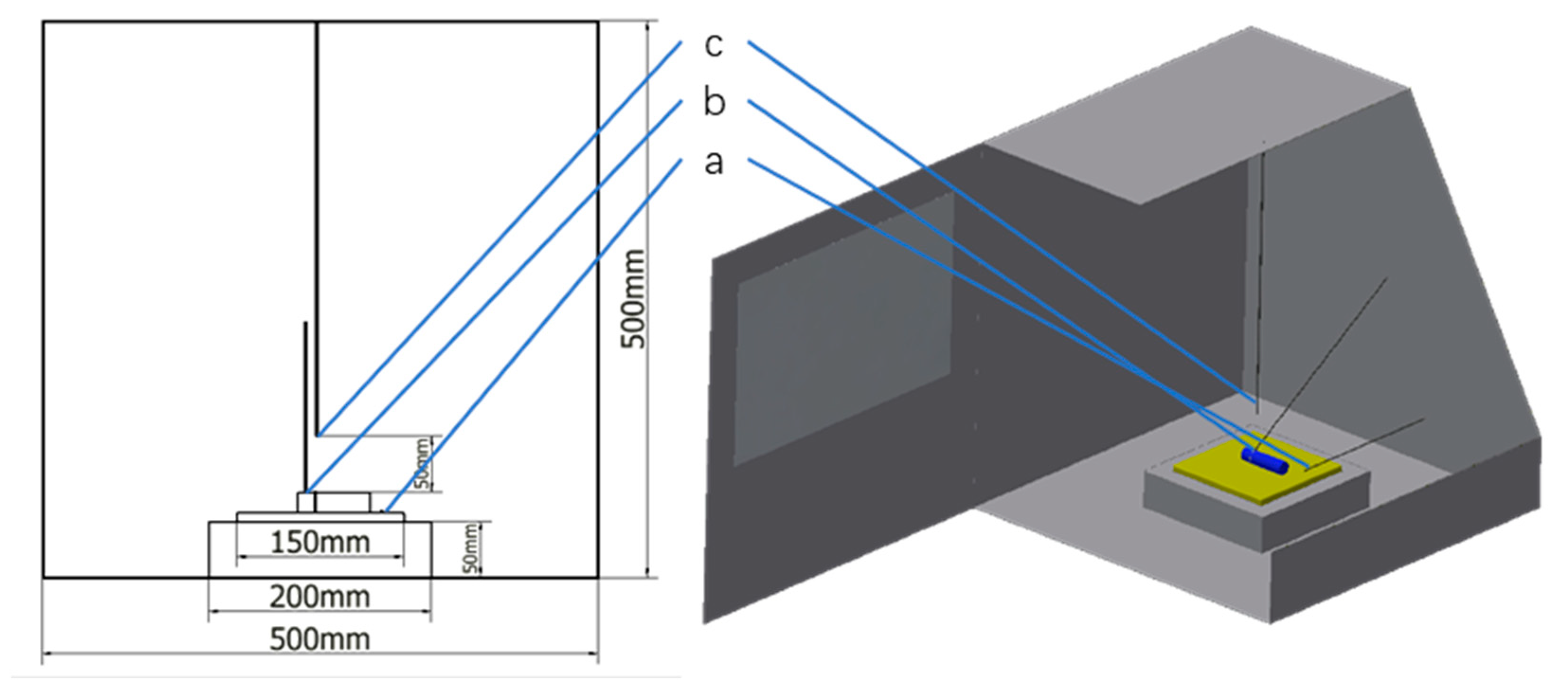
2.1. LIB Samples and Thermal Runaway Test Box

Abuse (overcharge, internal short circuit and external short circuit, hot stove) will accelerate the generation of internal heat of LIBs, and lagging of heat transmission will cause rapid accumulation of internal heat of the battery, which will eventually lead to thermal runaway of the battery [18,19,20,21,22,23]. By studying the decomposition and mutual reactions of various components in the battery, it can be seen that the thermal stability of LIB materials is the basis of safety [24,25,26,27]. When the cell temperature rises, the exothermic reactions that may occur inside the cell, such as the decomposition of the solid electrolyte interface (SEI) [28,29,30]; thermal decomposition of cathode materials [31,32,33,34]; thermal decomposition of anode materials [35,36,37]; thermal decomposition of the electrolyte on the cathode and redox reaction of the organic electrolyte on the cathode and anode [38,39,40]. The experimental samples used in this study were 18650 commercial batteries with the cathode material of LixNi1/3Co1/3Mn1/3O2 (NMC), LiCoO2 (LCO), LiFePO4 (LFP). Samples were pretreated by the Neware battery testing system, and four groups of samples with 0%, 30%, 50% and 100% SOC were obtained by processing each type of battery. The physical, chemical and electrical parameters of each battery are shown in the Table 1.
This experiment used an explosion-proof test box as the experimental platform, and the size of the box was 500 × 500 × 500 mm. The 18650 LIBs were heated by the electric heating plate to trigger the process of thermal runaway. The power of the electric heating plate was 1000 W, which was placed on the insulating brick. The LIB was fixed by an iron wire at the interface near the cathode and was placed on the center of the heating plate.
Three thermocouples were used to monitor the temperature of the electric heating plate surface, the battery surface and the gas environment. The positions are shown in Figure 1a–c, respectively. A high-frame-rate camera was placed on the surface of the explosion-proof glass in front of the test box to record the experimental phenomena. The battery residue was collected after the thermal runaway process. The experimental device is shown in Figure 1.

2.2. LIB Thermal Runaway Triggering Method

The commonly used trigger methods for thermal runaway include combustion trigger and electrothermal trigger [41,42,43]. Electrothermal triggering can accurately control the temperature of thermal runaway, which is convenient for simulating the process of thermal runaway caused by internal heat accumulation due to an internal short circuit, overcharge and other conditions. According to the existing theory, the thermal runaway of LIB is divided into three stages [44], namely, self-heating stage (50~140 °C), thermal runaway stage (140~850 °C) and thermal runaway termination stage (above 850 °C). In order to unify the experimental conditions for thermal runaway, the relationship between thermal runaway and trigger temperature of LIBs was studied. According to our previous research, among the three types of batteries (NMC, LCO, and LFP), LFP is the most stable, while 30% SOC is considered by most researchers to be a safer SOC. Therefore, it can be considered that if a certain condition can trigger the thermal runaway of 30% SOC LFP, it should be able to trigger the thermal runaway of other types and SOC of batteries. In this study, we selected 30% SOC LFP and the electrothermal trigger method, with a trigger temperature range of 100 to 190 °C and a heating rate of 10 °C·min−1, to study the relationship between the thermal runaway trigger (TRT) temperature and the TRT time. Finally, a unified and most likely triggering method was determined to study the thermal runaway process and toxic products of three types of lithium-ion batteries with different cathode materials.

2.3. Detection of LIBs Thermal Runaway Emissions

In addition to fire hazards, the toxicant generated by the thermal runaway of LIB is also one of its main hazards, which is flammable, easily asphyxiated, highly toxic, and has the threat of explosion [17,45,46,47]. According to early research, the leakage process of thermal runaway products of LIBs can be divided into two stages based on the time node of battery pressure relief valve rupture, namely, thermal runaway latency zone and thermal runaway behavior zone [48,49,50]. In the thermal runaway latency zone, the internal temperature of LIB is low, the chemical reaction rate is slow, and it is easy to generate small-molecule incomplete reaction products such as CO due to the internal hypoxia. In the thermal runaway behavior zone, with the increase in the internal temperature of the LIB and the acceleration of the chemical reaction rate, a large number of COx, SOx, C3~C8 organic substances and other flue gases are generated. At the same time, the oxygen content in the test box decreases sharply to below 19%, and there is a risk of explosion, which is very dangerous. Therefore, we adopted the following methods for the study of thermal runaway products. After the thermal runaway reaction was completed, the gas ambient temperature dropped to room temperature. The gas samples were 5 cm above the tested battery in the battery thermal runaway test box, which was collected by an air sampler, and it was analyzed by Hapsite Smart, which conducted the qualitative analysis of volatile and semi-volatile organic compounds. For solid ejectors, the battery wreckage after thermal runaway was collected, and the cathode material was separated from the wreckage. The XRD pattern was conducted by powder X-ray diffraction (Rigaku SmartLab, using the Cu- radiation as a primary source, operating at 40 kV, 200 mA). SEM analysis was performed on a ZEISS EVO 18 with an accelerated voltage of 5 kV and a resolution of 3 nm to observe the morphologies and surface changes of the samples. TEM analysis was performed on a HATACHI H-800 with an accelerated voltage of 100 kV and a lattice resolution of 0.204 nm to observe the ultrastructure of the sample particles and edges.

3. Results and Discussion

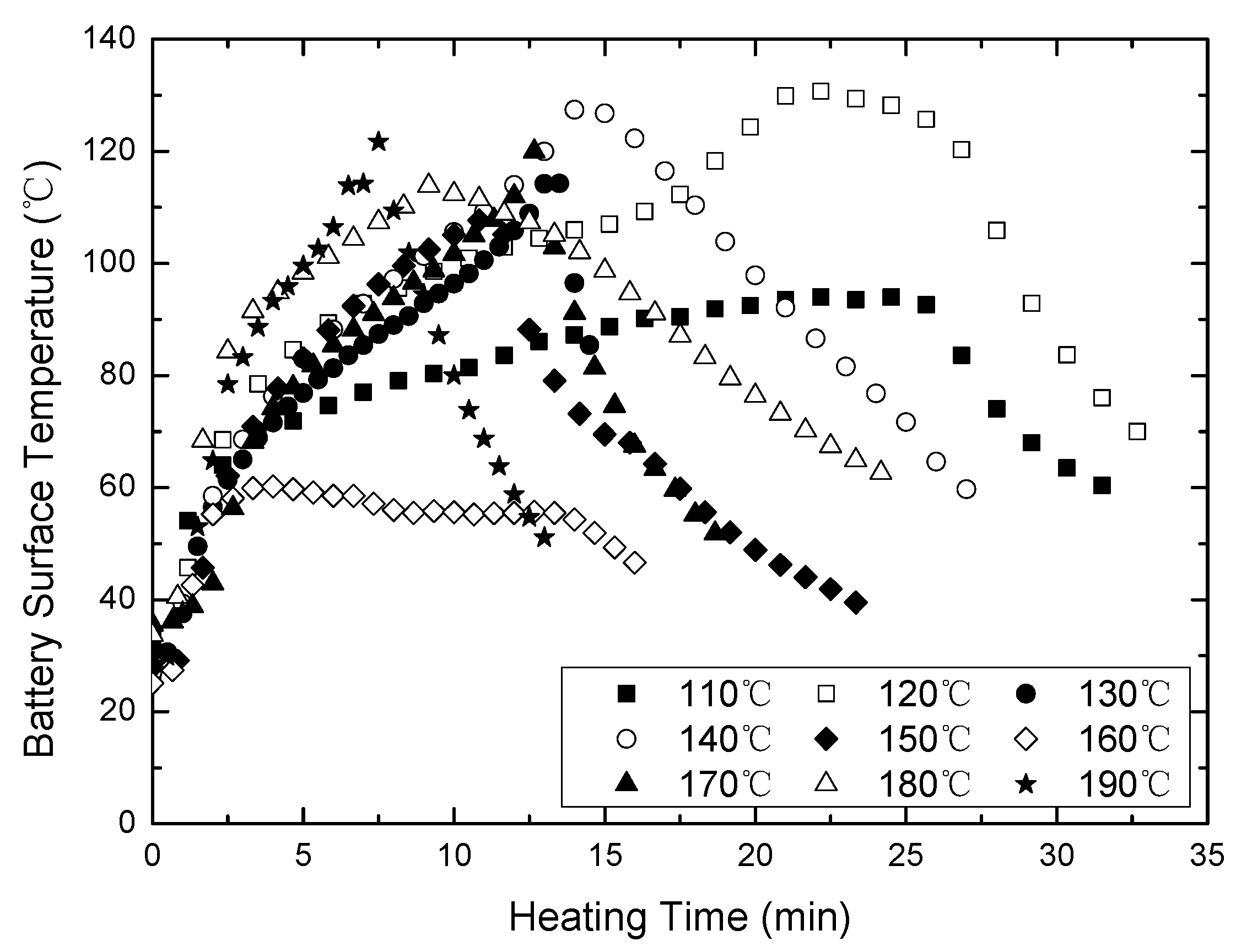
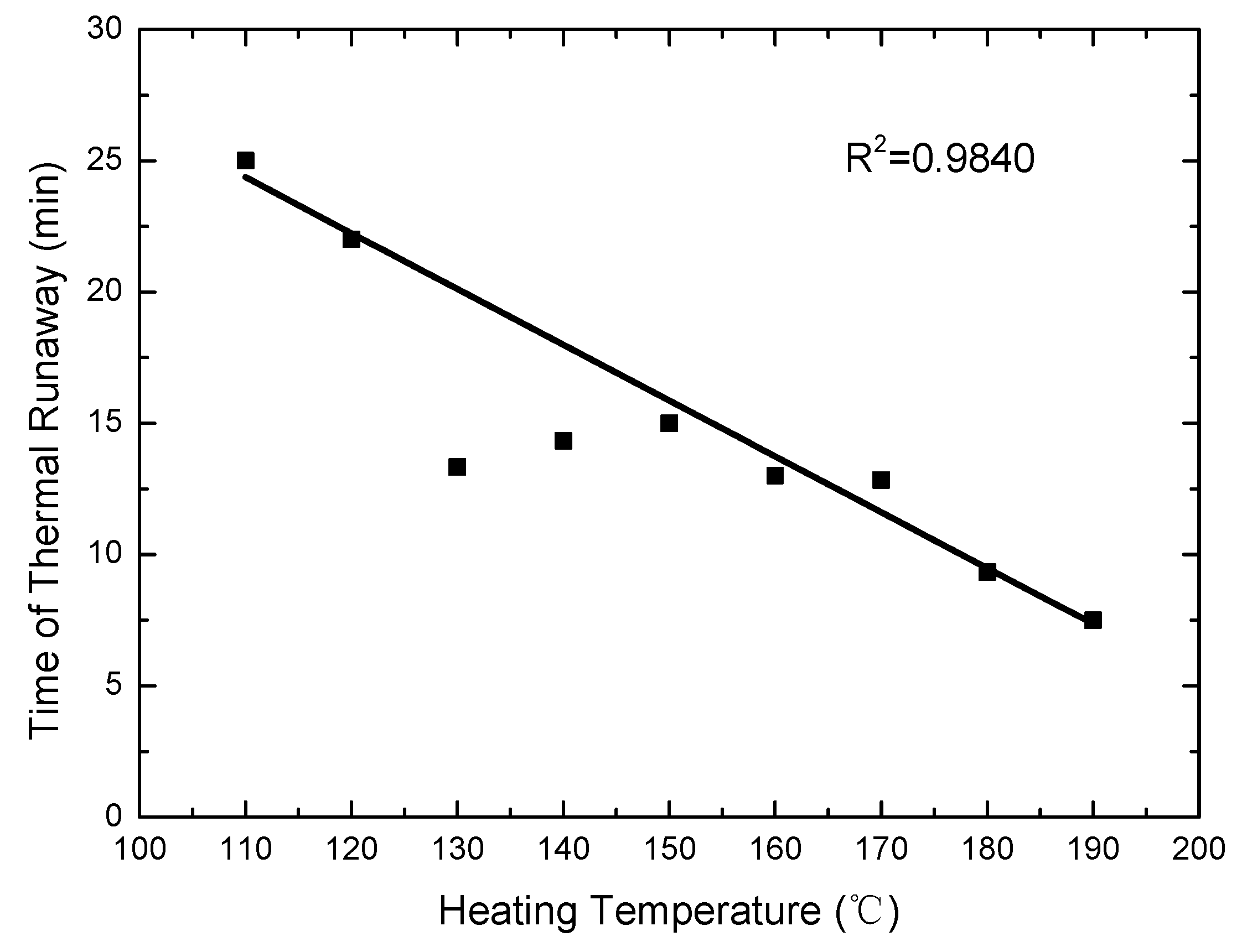
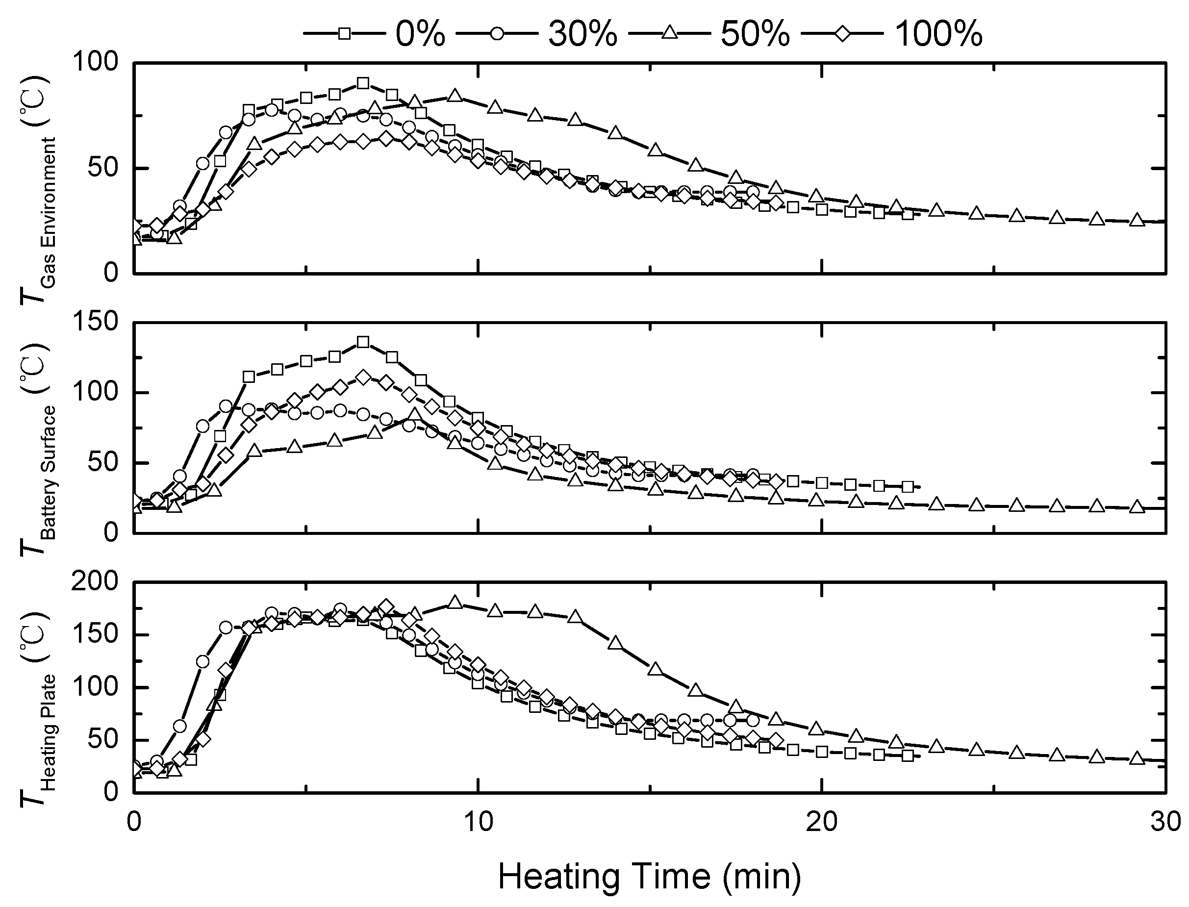
3.1. Determination of TRT Temperature

Using 100 °C + 10 °C × n (n = 1, 2, …, 9) as the TRT temperature and the turning point of temperature with time as the TRT mark (Figure 2), the relationship between the TRT temperature and the TRT time was studied. The first derivative of temperature versus time was calculated, and the TRT time with a derivative value of less than zero was recorded, as shown in Figure 3.
In our research, we found that using different numbers of heating plates, heating at different locations, and using different heating rates can significantly alter the triggering time of thermal runaway, the highest temperature after thermal runaway, and the severity of the battery thermal runaway. This may be due to the hysteresis of heat transfer inside the battery during the heating process, resulting in certain differences and temperature gradients in the horizontal and vertical directions, causing the thermal imbalance inside the battery to thermal runaway. At the same time, we also found that this change does not affect the generation and emission of toxic species after thermal runaway of lithium-ion batteries. Therefore, in this study, we can ignore the anisotropy of heat distribution and thermal gradient in the vertical direction caused by a single direction of heating in the battery, and the obtained condition can serve as a sufficient condition for triggering thermal runaway in lithium-ion batteries.
It can be seen from the relationship between the TRT temperature and the TRT time that the time required for the TRT decreases with the increase in TRT temperature. Considering the duration and operation feasibility of the experimental method, 170 °C was selected as the TRT temperature to trigger thermal runaway in the follow-up experiment.

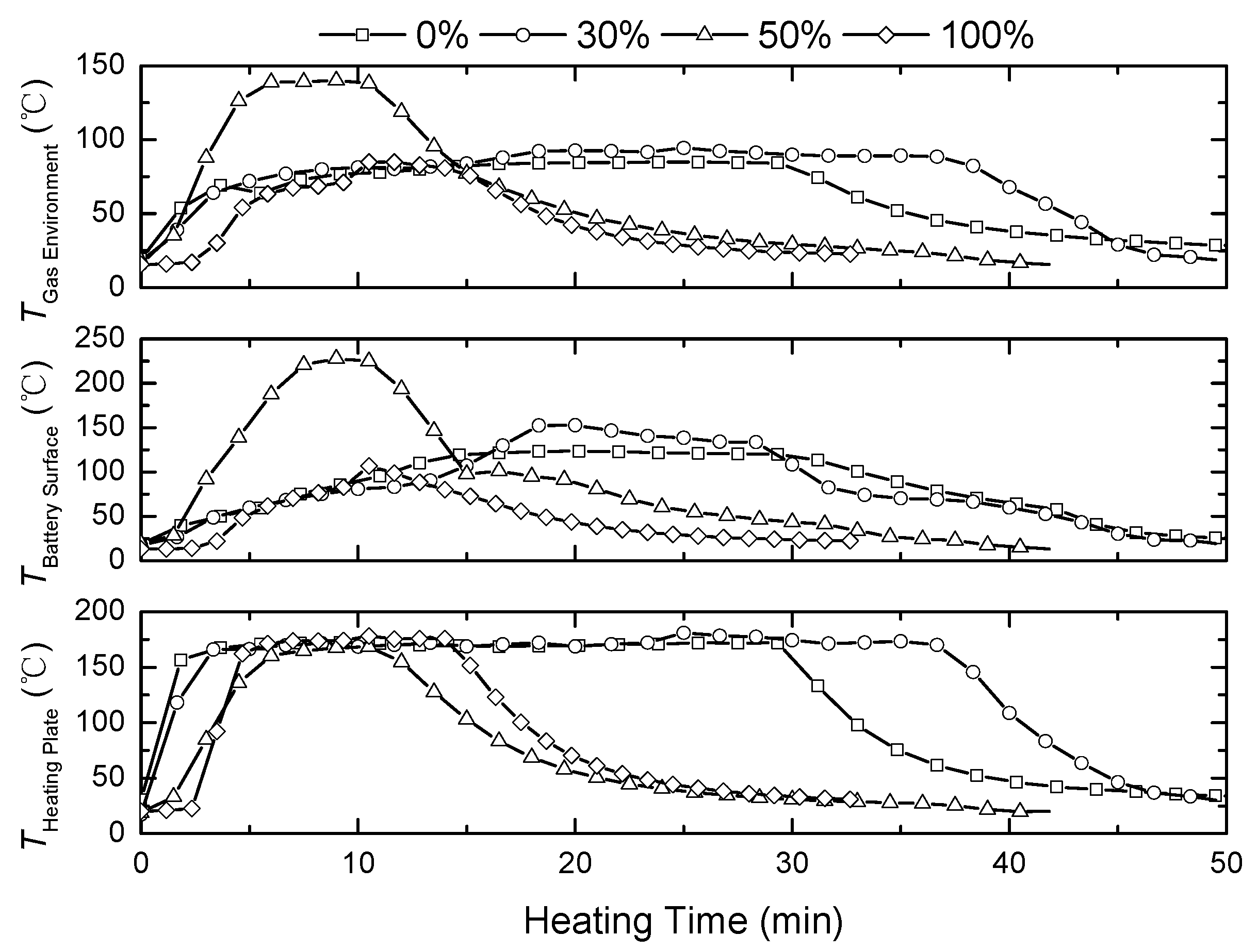
3.2. Analysis of Thermal Runaway Behaviors of LIBs

The thermal runaway experiment of 18650 battery under different SOC was conducted by means of electrothermal triggering, and the battery surface temperature was compared and analyzed in combination with video recording. The results are shown in Figure 4, Figure 5 and Figure 6.
After the electric heating plate was turned on, the surface temperature of each NMC with different SOC rose slowly. After heating for 2 min, the temperature rose rapidly, and the electrolyte leaked from the sealed part of the battery, accompanied by smoke generation. The heating rate tended to be flat after 4 min. At 9 min, a lot of electrolytes and smoke emitted from the battery. The phenomenon of battery samples at 30% and 50% SOC was particularly obvious, and the intensity of reaction increased with the increase in SOC. The 100% SOC battery samples even exploded and had an open flame.
At the beginning of the experiment, except for the 50% SOC sample, the temperature did not rise rapidly. Compared with NMC, there was no leakage of a large amount of electrolytes in the reaction stage of the battery. The reaction of 0% and 30% SOC samples was not violent, and the 50% SOC samples emitted less smoke compared with the NMC samples. The 100% SOC sample did not emit a lot of smoke before explosion, but the explosion reaction was violent.
The electrode material in LFP has good thermal stability and is not easy to reach thermal runaway in normal use. However, during the thermal runaway process triggered by electric heating, 0%, 50% and 100% SOC LFP all exploded, and the thermal stability of the 30% SOC LFP sample was better than the samples with the same cathode material. This indicates that 18650 LFP has poor stability in the electric heating process and is prone to thermal runaway in the event of thermal abuse. The high temperature during thermal abuse may cause internal structural damage to the battery (such as membrane melting, SEI decomposition, anode material disintegration, etc.), resulting in corresponding electrical abuse or mechanical abuse and leading to severe thermal runaway. At the same time, combined with the analysis of thermal runaway products, LFP with 0%, 50% and 100% SOC generated fewer large-molecule gaseous products after thermal runaway. The vast majority of carbon elements existed in the form of CO and CO2, resulting in a sharp increase in internal pressure of the battery. In addition, the 18650 battery packaging was relatively tight, and there was no time to release pressure. As a result, an explosion occurred.

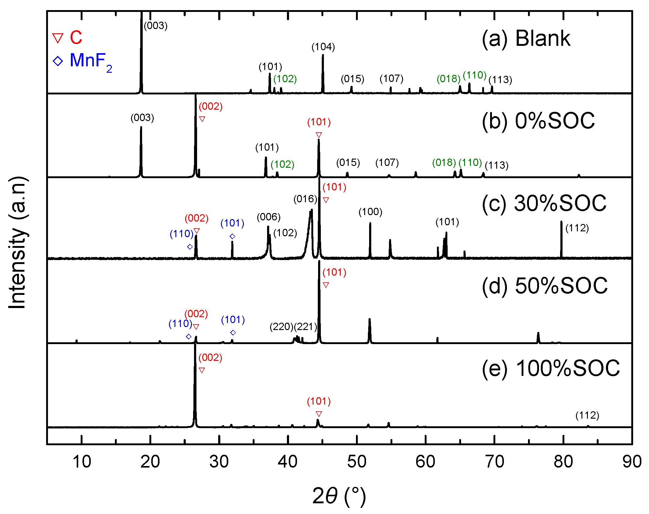
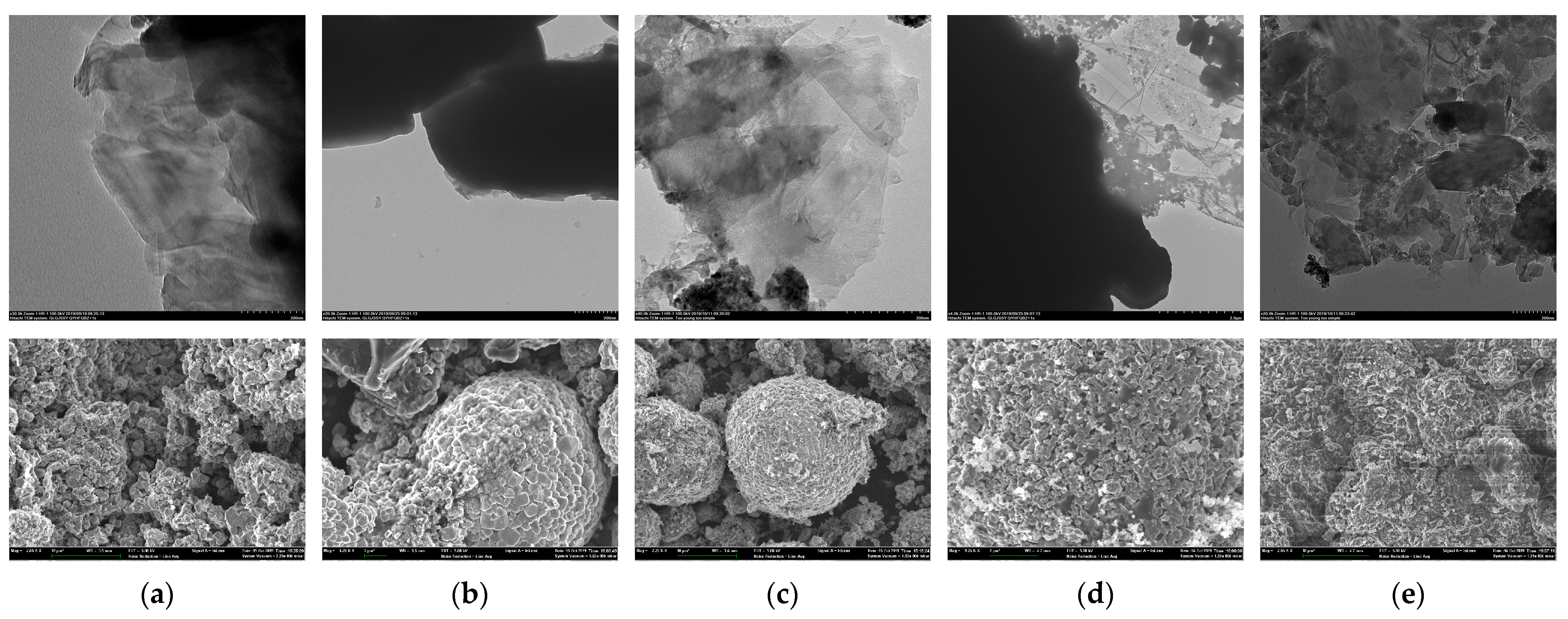
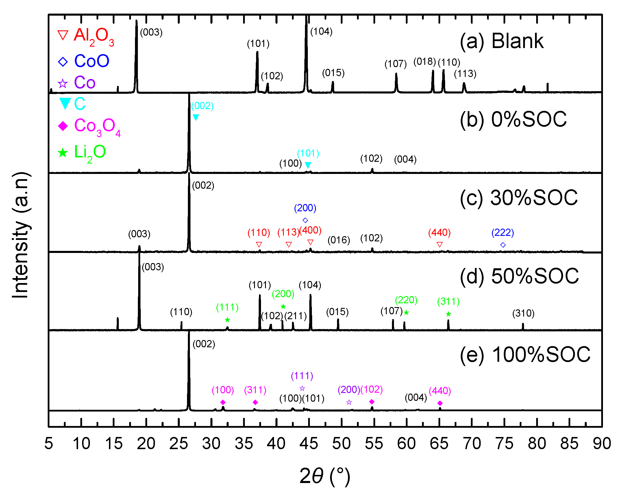
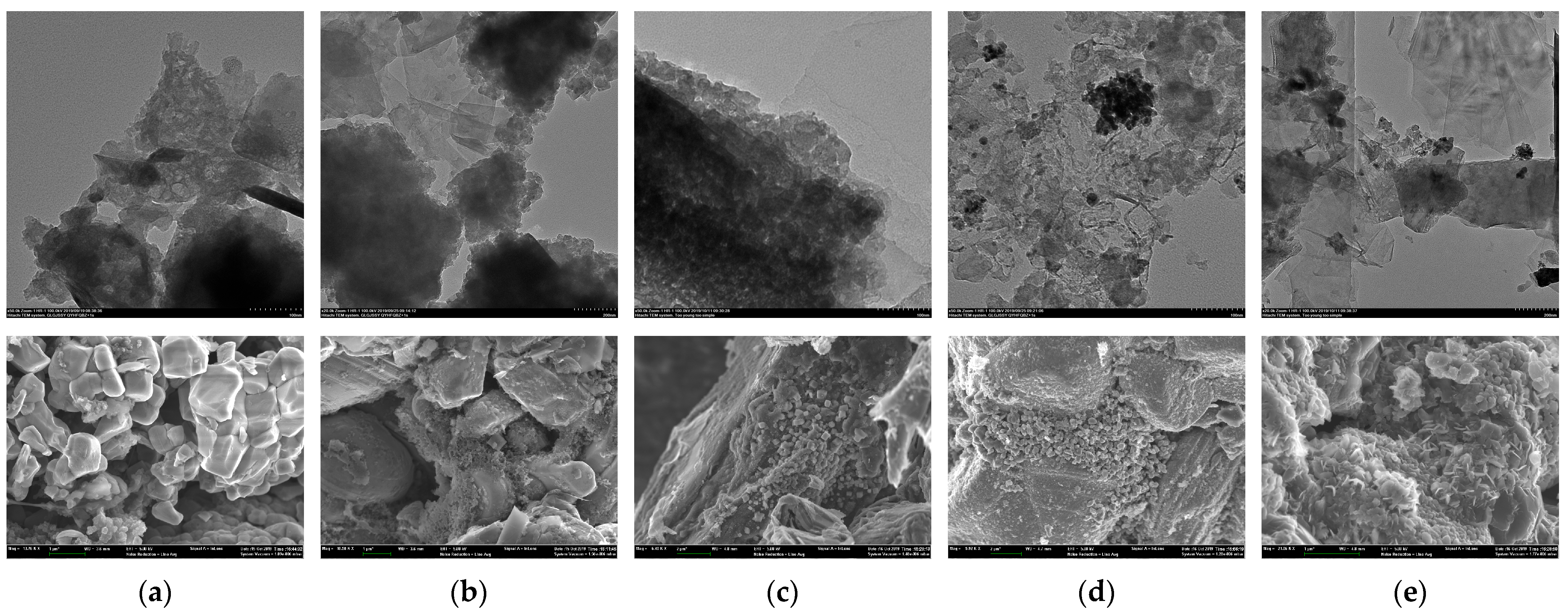
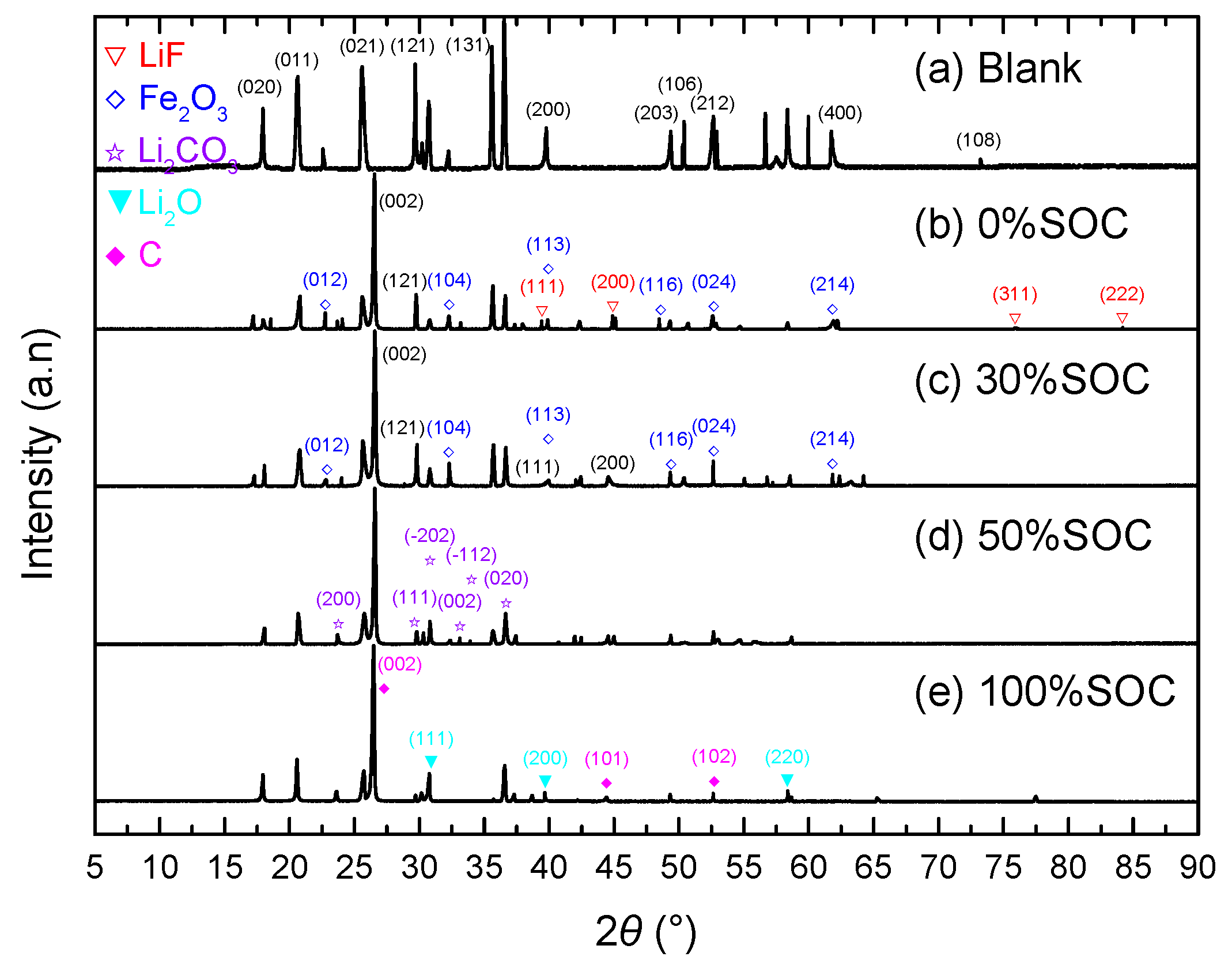
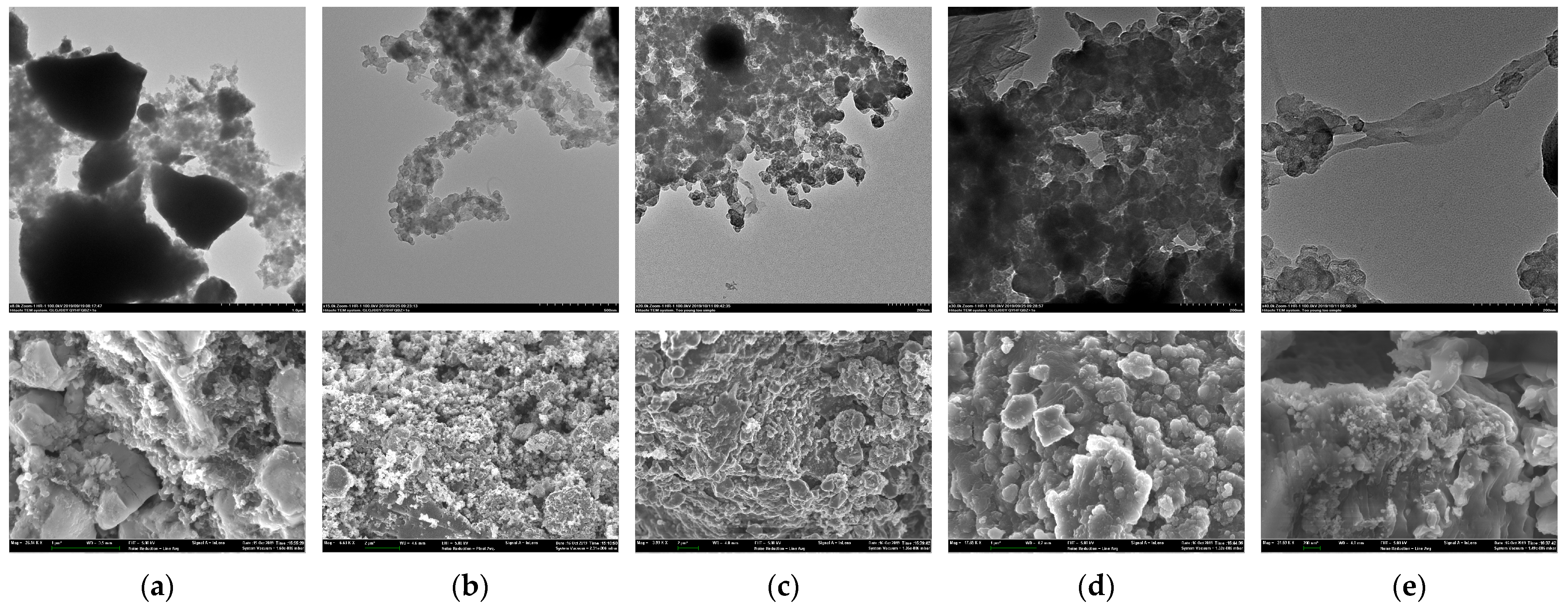
3.3. Characterization of Cathode Materials of LIB Thermal Runaway

After the thermal runaway test was completed, the cathode material of the battery was collected for electron microscope characterization and XRD detection and analysis. In the XRD spectrum of the blank sample of NMC before thermal runaway (Figure 7a), the splitting peak (006)/(102) was relatively weak, while the splitting peak (018)/(110) was relatively obvious, indicating that ternary materials have good layered morphology and representing that the blank sample has a relatively typical hexagonal layered crystal system structure. After the thermal runaway process, the above characteristic peaks of the 0% SOC NMC sample (Figure 7b) did not change much, indicating that the electrode structure had not been damaged. With the increase in SOC, the characteristic peaks (006)/(012) and (108)/(110) did not completely split or even disappear, indicating that during the thermal runaway process, the cathode material underwent decomposition and led to the destruction of the layered structure. In the spectrogram of 30% SOC (Figure 7c) and 50% SOC (Figure 7d) NMC samples, there were two diffraction peaks at 2θ = 25.8° and 32.7° that can be attributed to the (110) and (101) crystal planes of tetragonal MnF2, indicating that the cathode material reacted with the electrolyte after decomposition. It could be observed that the NMC samples with 0%, 30%, and 100% SOC (Figure 7b,c,e) have obvious carbon characteristic peaks (002) and (101), indicating that during the thermal runaway reaction, some carbon powder entered the cathode. However, 100% SOC NMC could observe the carbon characteristic peak only, which indicated that with the violent explosion, the cathode was completely destroyed and cannot be detected.
Figure 8 shows the transmission electron microscopic (TEM) and scanning electron microscopic (SEM) characterization of the cathode of NMC before and after thermal runaway, respectively. It can be seen from Figure 8a that the blank sample had a clear outline, which showed good crystallinity, good layered structure, and good regularity. It shows that the blank cathode sample of NMC was closely stacked by a layered structure, without adhesion, and had good morphology, which can be used as the blank control of this experiment. After the NMC thermal runaway reaction at 0% SOC (Figure 8b), the cathode material still had a compact layered morphology. The morphology of 0% SOC NMC batteries was maintained during the thermal runaway process. In the sample after the NMC thermal runaway reaction at 30% SOC (Figure 8c), the SEI was damaged, the layered structure was damaged and torn, and the existence of metal particles could be observed outside the broken cathode material. After the NMC thermal runaway reaction under 50% SOC (Figure 8d), the layered morphology was disrupted, and a large number of metal particles could be observed in the fragments. The graphite in the anode was also decomposed due to high temperature and entered the broken cathode. After the thermal runaway reaction of NMC at 100% SOC (Figure 8e), only fragments could be observed in the cathode sample. The metal particles could not be found, and the external impurities were doped into the structure.
Through XRD analysis of the wreckage of LCOs, it was found that the structure of all samples had changed. For the 0% SOC LCO, possibly due to the long-term high temperature, the membrane had been damaged, the anode carbon mixed into the cathode, and the characteristic peak of carbon was shown in the XRD spectrum (as shown in Figure 9b). In the 30% SOC LCO (Figure 9c), the cathode aluminum foil was oxidized at high temperature, as the characteristic peak of Al2O3 (110), (113), (400), (440) appeared at 2θ = 37.73°, 43.30°, 45.78° and 66.76°. In addition, the cathode material was decomposed and the characteristic peak of CoO (200), (222) was found in the spectrum at 2θ = 42.3° and 77.5°. Li2O was found in 50% SOC LCO samples (Figure 9d), indicating that Li was completely oxidized in the battery at high temperature. CoO and Co (111), (200) were found in the 100% SOC LCO samples (Figure 9e), which shows that after the cell membrane was melted, the cathode material would decompose and release oxygen (as shown in Formulas (1)–(3)).
Li x CoO 2 x LiCoO 2 + 1 x 3 Co 3 O 4 + 1 x 3 O 2
Co 3 O 4 3 CoO + 1 2 O 2
CoO Co + 1 2 O 2
From the electron microscopic characterization of the cathode of LCO before and after thermal runaway (Figure 10), we found that the blank sample (Figure 10a) had a loose porous structure, in which LiCoO2 particles were evenly distributed, a continuous conductive network was formed on the electrode surface, and a small amount of micropores existed. The surface of the blank cathode sample of LCO was relatively flat. This sample could be used as the blank control of this experiment. After the thermal runaway of the LCO cathode at 0% SOC (Figure 10b), part of the lithium cobalt oxide layered structure in the sample was torn and separated, and the porous structure collapsed. Due to the damage of the membrane, a small amount of carbon particles was mixed with the cathode. At the 30% SOC LCO (Figure 10c) cathode after thermal runaway, the layered structure was destroyed, but the metal particles were not ejected. After the LCO cathode thermal runaway reaction at 50% SOC (Figure 10d), the morphology of the cathode sample underwent significant changes, with metal particles ejected from it. After the LCO cathode thermal runaway reaction at 100% SOC (Figure 10e), the metal particles in the sample were damaged and might have reacted, and impurities were mixed with the material.
The characteristic diffraction peak of the blank sample of LFP (Figure 11a) is consistent with the standard diffraction peak. Compared with the blank sample, the 0% SOC LFP sample (Figure 11b) shows the same characteristic peak, indicating that graphite had also entered the cathode material. Impurity peaks of LiF (111), (200), (311), (222) and Fe2O3 (012), (104), (113), (116), (024), (214) were also found in it, indicating that the reaction on the anode will generate LiPF6, which will then decompose into LiF (Formula (4)) and enter the cathode through the broken membrane. At high temperature, the lattice of the cathode material was changed, showing an Fe2O3 impurity peak.
LiPF 6 LiF + PF 5
The spectrogram of the 30% SOC LFP sample (Figure 11c) is similar to that of the 0% SOC LFP sample. In the spectrogram of the 50% SOC LFP sample (Figure 11d), the existence of Li2CO3 was found, indicating that Li in the anode material reacted with the organic solvent to generate Li2CO3 (as shown in Formulas (5)–(7)).
2 Li + C 3 H 4 O 3 EC Li 2 CO 3 + C 2 H 4
2 Li + C 4 H 6 O 3 PC Li 2 CO 3 + C 3 H 6
2 Li + C 3 H 6 O 3 DMC Li 2 CO 3 + C 2 H 6
In the spectrum of the 100% SOC LFP sample (Figure 11e), the intensity of the characteristic peak of carbon is large, indicating that the Li material had been oxidized to Li2O.
Figure 11. XRD result of LFP with different SOC before and after thermal runaway.
Batteries 09 00308 g011
Figure 12 shows the electron microscopic characterization of the cathode of LFP before and after thermal runaway. It can be seen from Figure 12a that the blank sample had a clear contour, a good compact layered structure and good regularity. This shows that the cathode blank sample of LFP was closely stacked by the layered structure and had good morphology, which can be used as a blank control in this experiment. After the LFP thermal runaway reaction at 0% SOC (Figure 12b), the cathode material sample of LFP still retained the hexagonal layered crystal structure, and the metal particles were still uniformly loaded inside the gel. The morphology of samples after the LFP thermal runaway reaction at 30% SOC (Figure 12c) is similar to that of the samples after the LFP thermal runaway reaction at 0% SOC. As shown in Figure 12d, after the LFP thermal runaway reaction at 50% SOC, metal particles were ejected from the broken layered structures. The cathode material was decomposed at high temperature, and the graphite of the anode entered the cathode through the melted membrane. After the LFP thermal runaway reaction at 100% SOC (Figure 12e), the material structure was fragmented, and the pore structure was damaged.

3.4. Analysis of Thermal Runaway Gaseous Products of LIB

During the experiment, we found that all types of LIBs produce a large number of toxic and harmful species with different concentrations after thermal runaway, making it difficult to quantitatively evaluate the potential harm caused by the diffusion of toxicants after thermal runaway. At the same time, we found that the definitions of substance toxicity are also different domestically and internationally. Therefore, based on standards such as GBZ 230-2010 “Classification of Hazards of Occupational Exposure to Toxicant”, “WHO/IPC: The User’s Manual for the IPCS Health and Safety Guides”, and GB 38031-2020 “Electric Vehicles Traction Battery Safety Requirements”, etc., our research team established the standard of “Composition Detection Method and Toxicity Classification of Traction Battery Thermal Runaway Leakage” [51]. This standard specified the detection method for thermal runaway leakage of LIBs and the toxicity grading principles for leakage (as shown in Table 2).
Qualitative analysis of thermal runaway gaseous products in LIB was conducted through gas chromatography–mass spectrometry. The gaseous products of the thermal runaway of NMC are shown in Table 3, including two types of very toxic substances, 2-propenal and methyl vinyl ketone, and 19 types of highly toxic and toxic substances such as benzene and cyclopentadiene, etc. It can be seen from Table 3 that toxic substances were not detected in the thermal runaway reaction products of 0% SOC NMC. With the increase in the SOC of LIBs, more types of reaction products and higher toxicity products would be produced.
According to the analysis of the thermal runaway of NMC in Section 3.3, only a small amount of electrolyte leakage occurred during the reaction of 0% SOC NMC, and the maximum temperature of the battery surface did not exceed 100 °C; a small amount of smoke came out from the battery and stopped in a short time. The structure characterization also proved that the hexagonal layered crystal structure of the battery sample remained after the thermal runaway process, indicating that the thermal runaway of this group of samples was relatively mild, and the gaseous products could not be detected by GC-MS.
With 30% and 50% SOC, the cathode protection cover burst out, and a large amount of smoke was emitted during the reaction of NMC thermal runaway, indicating that these two groups of samples reacted violently during the thermal runaway process. The surface temperature of the battery exceeded 200 °C, and the SEI was decomposed. The internal pressure of the battery increased, which burst the cathode protection cover. The battery membrane melted, and an internal short circuit occurred in the battery, which promoted the decomposition of the electrolyte and cathode material.
The thermal runaway of NMC with 100% SOC was the strongest compared with the other SOC of NMC samples. There was a large amount of gaseous products generated in the early stage, an explosion occurred in the later stage, and the internal structure of the battery was damaged. With 100% SOC, NMC had the majority of types of thermal runaway products, especially toxic substances with strong toxicity.
The thermal runaway emission products of LCOs are shown in Table 4. Compared with other SOC of LCOs, 100% SOC LCO thermal runaway emissions generated the majority of types and higher toxicity products. Among the emission products, four types of very toxic substances, such as 2-propenal, methyl vinyl ketone, propanedinitrile and propanenitrile, were found. These four substances were also found in the thermal runaway emission products of other types of LCO in the early work of our research group. In addition, there were 30 types of highly toxic and toxic gaseous products. Moreover, compared with other types of LIB thermal runaway products, there were more types of aromatic substances in the thermal runaway products of LCO.
Most of the toxicants existed in the thermal runaway emission products of LCO with 50% and 100% SOC, and GC-MS did not detect toxic substances in the thermal runaway products of 0% SOC LCO. Only isobutylene was detected in the thermal runaway products of LCO with 30% SOC. Four very toxic species, especially 2-propenal, methyl vinyl ketone, propanedinitrile and propanenitrile, were found in the thermal runaway products of LCO with 100% SOC. During the thermal runaway experiment, the battery had a violent combustion reaction, and the current collector had combusted after the battery explosion. LCO with 50% and 100% SOC were similar in the products of highly toxic and toxic emissions.
Compared with other types of LIBs, the least amount of types of thermal runaway products were detected by LFP (as shown in Table 5), but two types of very toxic substances containing nitrogen, such as 1,2-dimethyl-hydrazine and thiocyanic acid ethyl ester, were detected, and most of the toxic products were detected in LFP with 30% SOC. In the thermal runaway test of LFP, this might be due to the explosion of the battery a short time after heating, except for the LFP at 30% SOC. Many kinds of nitrogen-containing compounds were detected in the emission products, and 1,2-dimethylhydrazine was converted from these compounds as a very toxic nitrogen-containing compound.
In the thermal runaway test, a total of six types of very toxic species were detected, and we preliminarily speculated on their formation mechanisms.
  • 2-Propenal (CAS#107-02-8, C3H4O)
2-propenal was detected in the thermal runaway products of 30% SOC NMCs, 30% SOC and 50% SOC LCOs. The high temperature generated by thermal runaway caused damage to the internal structure of the battery. Electrolyte solvents (such as EC, PC, DMC) entered the anode and reacted with the lithium, generating small-molecule hydrocarbon compounds (as shown in Formulas (5)–(7)). The propylene generated by the reaction between PC and lithium was continuously oxidized to form acrolein at high temperature (as shown in Formulas (8) and (9)).
2 Li + C 4 H 6 O 3 PC Li 2 CO 3 + C 3 H 6
C 3 H 6 + O 2 CH 2 = CH CHO + H 2 O
Otherwise, the electrolyte solvents were decomposed to produce propylene glycol, which was continuously oxidized to acrolein at high temperature (as shown in Formula (10)).
HOCH 2 CH 2 CH 2 OH CH 2 = CH CHO + 2 H 2 O
Otherwise, it was obtained by the mutual conversion of propanol and acrylic acid in the thermal runaway products of LCO and LFP in high temperature environment (as shown in Formula (11)).
CH 2 CH 2 CH 2 OH O CH 2 = CHCHO O CH 2 CH 2 COOH
2.
Methyl vinyl ketone (CAS#78-94-4, C4H6O)
Methyl vinyl ketone was detected in 100% SOC NMC and 100% SOC LCO. It is speculated that the first step was to decompose the electrolyte to produce aldehydes and ketones, and the acetone in it reacted with formaldehyde at high temperature to produce butenone after dehydration (as shown in Formula (12)).
CH 2 COCH 3 + HCHO Δ CH 3 COCH = CH 2
3.
Propanenitrile (CAS#107-12-0, C3H5N)
Propanenitrile could be found in 100% SCO LCO batteries and is usually obtained by hydrogenation of acrylonitrile. Previous research had shown that direct decomposition of the electrolyte [52] or the reaction of lithium dendrites with the anode material adhesive [53] will generate hydrogen, which can hydrogenate and reduce acrylonitrile to propionitrile (as shown in Formula (13)). Acrylonitrile might be generated by the reaction of acetonitrile and formaldehyde in electrolyte additives (as shown in Formula (14)) [54]. Due to the strong activity of the catalyst (such as cobalt oxide, lithium oxide, etc., generated by the decomposition of electrode materials), it could lead to the further oxidation of propionitrile to propylamine (as shown in Formula (15)), which in turn disproportionated into ammonia and dipropylamine (as shown in Formula (16)) [55]. The occurrence of this step could be demonstrated by the presence of dipropylamine in the product after the LCO battery thermal runaway (as shown in Supplementary Material Table S1).
CH 2 = CH CN + H 2 CH 3 CH 2 CN
CH 3 CN + HCHO CH 2 = CH CN
CH 3 CH 2 CN + H 2 CH 3 CH 2 CH 2 NH 2
2 CH 3 CH 2 CH 2 NH 2 HNCH 2 CH 2 CH 3 2 + NH 3
4.
Propanedinitrile (CAS#109-77-3, C3H2N2)
Propanedinitrile could be found in the thermal runaway products of 100% SOC LCO batteries. It can usually be prepared by the acrylonitrile method [56]. Acrylonitrile gradually formed malonitrile under the action of alcohols decomposed from the electrolyte solution (as shown in Formula (17)).
CH = CH CN + ROH NC CH OH 2 NC CHO NC CH 2 CN
Otherwise, it could be prepared by the styrene method [56]. The small molecule olefins generated by the electrolyte solvent and lithium were polymerized into benzene, which then reacted with ethylene to generate styrene (as shown in Table S1). Propanedinitrile was obtained as follows (as shown in Formula (18)).
C 6 H 5 CH = CH 2 C 6 H 5 CH 2 OR 2 C 6 H 5 CH 2 CHO NC CH 2 CN
5.
Thiocyanic acid ethyl ester (CAS#542-90-5, C3H5NS)
Thiosyanic acid ethyl ester could be found in 30% SOC LFP batteries. Due to the structure of the 30% SOC battery remaining intact after thermal runaway, the cyanide and thiocyano groups in the electrolyte additives [57] were not damaged by high temperature, and they might have reacted with alcohols and thiols (as shown in Table S1) obtained from electrolyte decomposition in the thermal runaway products to generate thiocyanate ester compounds (as shown in Formulas (19) and (20)).
CH 3 CH 2 OH + SCN CH 3 CH 2 SCN
CH 3 CH 2 SH + CN CH 3 CH 2 SCN
6.
1,2-dimethyl-hydrazine (CAS#540-73-8, C2H8N2)
1,2-dimethyl-hydrazine could be found in 100% SOC LFP batteries. Under the intense thermal runaway process, cyanide compounds in the electrolyte additive decomposed into ammonia, which reacted with the ketones produced by the electrolyte decomposition to undergo a ketazine reaction and which hydrolyzed to obtain hydrazine (as shown in Formulas (20) and (21)) [58]. Trichlorotoluene in flame-retardant additives underwent hydrolysis at high temperatures to form benzoyl chloride (as shown in Formula (23)) [59]. Benzoyl chloride reacted with ammonia to produce dibenzoyl hydrazine, which reacted with dimethyl carbonate in the electrolyte to obtain symmetric dibenzoyl dimethyl hydrazine. Under the action of acid, 1,2-dimethylhydrazine was formed (as shown in Formulas (24)–(26)) [60].
NH 3 + R 1 R 2 CO R 1 R 2 C = N N = CR 1 R 2
R 1 R 2 C = N N = CR 1 R 2 + 2 H 2 O 2 R 1 R 2 CO + NH 2 NH 2
C 6 H 5 CCl 3 + H 2 O Fe 3 + ,   90 ~ 120 C 6 H 5 COCl + 2 HCl
C 6 H 5 COCl + N 2 H 4 C 6 H 5 CONHNHCOC 6 H 5 CH 3 NHNHCH 3
C 6 H 5 CONHNHCOC 6 H 5 + 2 CH 3 COOCH 3 C 6 H 5 CON CH 3 N CH 3 COC 6 H 5
C 6 H 5 CON CH 3 N CH 3 COC 6 H 5 CH 3 NHNHCH 3 + 2 C 6 H 5 COOH

4. Conclusions

The abuse test under the simulated thermal, electrical and other environmental conditions is the key step of the general safety test. In this work, the TRT of 18650 LIBs was carried out using the electrothermal trigger method. The temperature condition of the LIB sample and the emission products were detected and analyzed, the battery thermal chemistry reaction product formation mechanism was briefly inferred, and the following results were obtained:
(1) The feasibility of thermal runaway of LIB triggered by the electrothermal method has been verified. The LIB thermal runaway electric trigger device was built and used to conduct the electric trigger test of LFP at 30% SOC at different trigger temperatures. The relationship between the TRT time and the TRT temperature was observed. The trigger time of thermal runaway is generally linear with the trigger temperature. A temperature of 170 °C was determined as the TRT temperature in this work.
(2) The thermal runaway processes of LIBs at different SOC were explored by the electrothermal trigger thermal runaway experiment of three types of LIBs (NMC, LCO and LFP) at 0%, 30%, 50% and 100% SOC. For the NMC and LCO, with the increase in the SOC of the LIB, the LIB was more prone to thermal runaway, and the TRT temperature was lower, resulting in more severe damage to the electrode material. The battery with higher SOC was more prone to explosion. For LFP, only the 30% SOC battery was the most stable, and the change in the cathode material after the reaction was the smallest. As the SOC increased, the degree of material damage inside the battery increased, as well as the degree of the internal short circuit and thermal runaway.
(3) GC-MS was used to qualitatively detect and analyze the thermal runaway gaseous products of the battery. Dozens of toxic substances can be detected in thermal runaway products of LIBs with different cathode materials and SOC, among which six very toxic substances such as 2-propenal, methyl vinyl ketone, propanedinitrile, propanenitrile, 1,2-dimethyl-hydrazine and thiocyanic acid ethyl ester could be detected and analyzed. For NMC and LCO, high-SOC batteries had more types of products than low-SOC batteries. For LFP, most types of toxic products were detected in 30% SOC battery samples. At the same time, it was found that certain substances used as electrolyte solvents or additives may react with electrode materials or thermal runaway products during the thermal runaway process, generating new products with higher toxicity. Therefore, when choosing electrolyte solvents and various functional additives containing elements such as N, S, Cl, etc., more serious concern is needed.

Supplementary Materials

The following supporting information can be downloaded at: https://www.mdpi.com/article/10.3390/batteries9060308/s1, Table S1: List of all products of thermal runaway for three types of batteries.

Author Contributions

Conceptualization, J.S.; Data curation, T.Z.; Formal analysis, T.Z. and H.X.; Funding acquisition, L.C.; Investigation, T.Z., J.S., J.L., S.W., J.C., S.D., N.T., Y.Z., F.Z. and H.L.; Methodology, T.Z., J.S. and J.L.; Project administration, Y.L. and J.G.; Resources, J.S.; Software, T.Z.; Supervision, X.Q.; Validation, J.S.; Visualization, T.Z. and H.X.; Writing—original draft, T.Z.; Writing—review & editing, J.S. All authors have read and agreed to the published version of the manuscript.

Funding

This research was funded by the National Natural Science Foundation of China, grant number 51551204 and by the National Key Research and Development Program of China, grant number 2018YFB0104404.

Data Availability Statement

Not applicable.

Acknowledgments

Financial support from the Emergency Management project “Research of toxics from Li-ion battery thermal runaway” of the National Natural Science Fund of China and from “Quantitative Evaluation Technology of Power Battery System Performance” of the National Key Research and Development Program of China are both appreciated.

Conflicts of Interest

The authors declare no conflict of interest.

References

  1. Guyomard, D.; Tarascon, J.M. Rocking-Chair or Lithium-Ion Rechargeable Lithium Batteries. Adv. Mater. 1994, 6, 408–412. [Google Scholar] [CrossRef]
  2. Yang, H.; Bang, H.; Amine, K.; Prakash, J. Investigations of the exothermic reactions of natural graphite anode for Li-ion batteries during thermal runaway. J. Electrochem. Soc. 2005, 152, A73–A79. [Google Scholar] [CrossRef]
  3. Shahid, S.; Agelin-Chaab, M. A review of thermal runaway prevention and mitigation strategies for lithium-ion batteries. Energy Convers. Manag. X 2022, 16, 100310. [Google Scholar] [CrossRef]
  4. Song, L.; Zheng, Y.; Xiao, Z.; Wang, C.; Long, T. Review on Thermal Runaway of Lithium-Ion Batteries for Electric Vehicles. J. Electron. Mater. 2022, 51, 30–46. [Google Scholar] [CrossRef]
  5. Wang, H.; Zhu, X.; Wang, Z.; Cong, W. Review of Thermal Runaway and Safety Management for Lithium-ion Traction Batteries in Electric Vehicles. J. Mech. Eng. 2021, 56, 91–118. [Google Scholar]
  6. Lyu, P.; Liu, X.; Qu, J.; Zhao, J.; Huo, Y.; Qu, Z.; Rao, Z. Recent advances of thermal safety of lithium ion battery for energy storage. Energy Storage Mater. 2020, 31, 195–220. [Google Scholar] [CrossRef]
  7. The Ministry of Public Security of the People’s Republic of China. The Total Number of Motor Vehicles in China Reached 417 Million, with over 500 Million Drivers and 13.1 Million New Energy Vehicles, a Year-on-Year Increase of 67.13%. Available online: https://www.mps.gov.cn/n2254314/n6409334/c8837510/content.html (accessed on 11 January 2023).
  8. Zhou, Y.; Wang, Z.; Hong, J.; Qu, C.; Shan, T.; Zhang, J.; Hou, Y. Review of Overcharge-to-thermal Runaway and the Control Strategy for Lithium-ion Traction Batteries in Electric Vehicles. J. Mech. Eng. 2022, 58, 112–135. [Google Scholar]
  9. Jia, Z.; Wang, Z.; Wang, Q.; Li, X.; Sun, F. Research on Thermal Runaway Mechanism and Safety Risk Control Method of Power Battery in New-Energy Vehicles. Automot. Eng. 2022, 44, 1689–1705. [Google Scholar]
  10. Qi, Z.; Liu, W.; Qi, W.; Li, X.; Wang, P.; Fang, S. Analysis and Research Status of The Cause of Thermal Runaway of Lithium Battery. In Proceedings of the International Conference on Optoelectronic Materials and Devices (ICOMD 2021), Guangzhou, China, 10 December 2021; SPIE: Bellingham, WA, USA, 2022; Volume 12164. [Google Scholar]
  11. Shan, T.; Wang, Z.; Hong, J.; Qu, C.; Zhang, J.; Zhou, Y.; Hou, Y. Overview of “Mechanical Abuse-thermal Runaway” of Electric Vehicle Power Battery and Its Safety Prevention and Control Technology. J. Mech. Eng. 2022, 58, 252–275. [Google Scholar]
  12. Feng, X.; Ouyang, M.; Liu, X.; Lu, L.; Xia, Y.; He, X. Thermal runaway mechanism of lithium ion battery for electric vehicles: A review. Energy Storage Mater. 2018, 10, 246–267. [Google Scholar] [CrossRef]
  13. Ren, D.; Feng, X.; Liu, L.; Hsu, H.; Lu, L.; Wang, L.; He, X.; Ouyang, M. Investigating the relationship between internal short circuit and thermal runaway of lithium-ion batteries under thermal abuse condition. Energy Storage Mater. 2021, 34, 563–573. [Google Scholar] [CrossRef]
  14. Dubois, E.R.; Kherbouchi, H.; Bosson, J. Thermal Runaway of Lithium-Ion Batteries Triggered by Electromagnetic Interference. IEEE Trans. Electromagn. Compat. 2020, 62, 2096–2100. [Google Scholar] [CrossRef]
  15. Golubkov, A.W.; Scheikl, S.; Planteu, R.; Voitic, G.; Wiltsche, H.; Stangl, C.; Fauler, G.; Thaler, A.; Hacker, V. Thermal runaway of commercial 18650 Li-ion batteries with LFP and NCA cathodes-impact of state of charge and overcharge. RSC Adv. 2015, 5, 57171–57186. [Google Scholar] [CrossRef] [Green Version]
  16. Yuan, Q.; Xu, X.; Zhu, L.; Tong, G. Effects of Local Thermal Accumulation Conditions on the Thermal Characteristics of Lithium-Ion Batteries under High-Rate Charging. J. Energy Eng. 2020, 146, 04020072. [Google Scholar] [CrossRef]
  17. Sun, J.; Li, J.; Zhou, T.; Yang, K.; Wei, S.; Tang, N.; Dang, N.; Li, H.; Qiu, X.; Chen, L. Toxicity, a serious concern of thermal runaway from commercial Li-ion battery. Nano Energy 2016, 27, 313–319. [Google Scholar] [CrossRef]
  18. Wei, D.; Zhang, M.; Zhu, L.; Chen, H.; Huang, W.; Yao, J.; Yuan, Z.; Xu, C.; Feng, X. Study on Thermal Runaway Behavior of Li-Ion Batteries Using Different Abuse Methods. Batteries 2022, 8, 201. [Google Scholar] [CrossRef]
  19. Spotnitz, R.; Franklin, J. Abuse behavior of high-power, lithium-ion cells. J. Power Sources 2003, 113, 81–100. [Google Scholar] [CrossRef]
  20. Li, Y.; Liu, G.; Li, Z. Numerical modeling of thermal runaway in high-energy lithium-ion battery packs induced by multipoint heating. Case Stud. Therm. Eng. 2022, 38, 102335. [Google Scholar] [CrossRef]
  21. Shelkea, A.V.; Buston, J.E.; Gill, J.; Howard, D.; Williams, R.C.; Read, E.; Abaza, A.; Cooper, B.; Richards, P.; Wen, J.X. Combined numerical and experimental studies of 21700 lithium-ion battery thermal runaway induced by different thermal abuse. Int. J. Heat Mass Transf. 2022, 194, 123099. [Google Scholar] [CrossRef]
  22. Kwak, E.; Kim, J.; Hong, S.H.; Oh, K. Detailed modeling investigation of thermal runaway pathways of a lithium iron phosphate battery. Int. J. Energy Res. 2022, 46, 1146–1167. [Google Scholar] [CrossRef]
  23. Zhao, W.; Rohde, M.; Mohsin, I.U.; Ziebert, C.; Du, Y.; Seifert, H.J. Combined Thermal Runaway Investigation of Coin Cells with an Accelerating Rate Calorimeter and a Tian-Calvet Calorimeter. Batteries 2022, 8, 15. [Google Scholar] [CrossRef]
  24. Cheng, Q.; Lan, Q.; Zhao, J.; Liu, C.; Cao, Y. Research Progress of Causes and Countermeasures on Thermal Runaway of Lithium Ion Battery. J. Jianghan Univ. Nat. Sci. Ed. 2018, 46, 11–16. [Google Scholar]
  25. Huang, P. Research on the Fire Risk of Lithium Ion Battery and the Critical Condition of Thermal Runaway Behavior; University of Science and Technology of China: Hefei, China, 2018. [Google Scholar]
  26. Luo, Q. Experimental Study on Thermal Runaway Process of Lithium Ion Batteries under Charging and Discharging Conditions; Nanjing Tech University: Nanjing, China, 2015. [Google Scholar]
  27. Zhao, X. Heat Generation of Lithium Ion Battery during Cycling under Adiabatic Condition; University of Science and Technology of China: Hefei, China, 2014. [Google Scholar]
  28. Winter, M.; Appel, W.K.; Evers, B.; Hodal, T.; Möller, K.-C.; Schneider, I.; Wachtler, M.; Wagner, M.R.; Wrodnigg, G.H.; Besenhard, J.O. Studies on the Anode/Electrolyte Interface in Lithium Ion Batteries. Mon. Chem. 2001, 132, 473–486. [Google Scholar] [CrossRef]
  29. Wang, Q.; Zhang, P.; Zhu, W.; Zhang, D.; Li, Z.; Wang, H.; Sun, H.; Wang, B.; Fan, L.-Z. A two-step strategy for constructing stable gel polymer electrolyte interfaces for long-life cycle lithium metal batteries. J. Mater. 2022, 8, 1048–1057. [Google Scholar] [CrossRef]
  30. Tanaka, N.; Bessler, W.G. Numerical investigation of kinetic mechanism for runaway thermo-electrochemistry in lithium-ion cells. Solid State Ion. 2014, 262, 70–73. [Google Scholar] [CrossRef]
  31. Jia, L.; Wang, D.; Yin, T.; Li, X.; Li, L.; Dai, Z.; Zheng, L. Experimental Study on Thermal-Induced Runaway in High Nickel Ternary Batteries. ACS Omega 2022, 7, 14562–14570. [Google Scholar] [CrossRef]
  32. Mei, W.; Duan, Q.; Wang, Q.; Li, Y.; Li, X.; Zhu, J.; Wang, Q. Thermal runaway simulation of large-scale lithium iron phosphate battery at elevated temperatures. Energy Storage Sci. Technol. 2021, 10, 202–209. [Google Scholar]
  33. Hu, Y.; Li, Y.; Lian, F.; Zhong, S.; Li, P. The study of the thermal runaway of Li-ion batteries. Chin. J. Power Sources 2006, 30, 833–836. [Google Scholar]
  34. Gang, M.B.; Kim, N.J. Numerical analysis on thermal runaway by cathode active materials in lithium-ion batteries. J. Korean Soc. Geotherm. Hydrothermal Energy 2021, 17, 1–10. [Google Scholar]
  35. Liu, Y.; Tian, Q.; Zhu, J. Reviewed on thermal stability of anode material for lithium-ion battery. New Chem. Mater. 2012, 40, 28–30. [Google Scholar]
  36. Wang, C.-J.; Zhu, Y.-L.; Gao, F.; Wang, K.-K.; Zhao, P.-L.; Meng, Q.-F.; Wu, Q.-B. Morphology, Structure, and Thermal Stability Analysis of Aged Lithium-Ion Battery Materials. J. Electrochem. Soc. 2020, 167, 140550. [Google Scholar] [CrossRef]
  37. Barkholtz, H.M.; Preger, Y.; Ivanov, S.; Langendorf, J.; Torres-Castro, L.; Lamb, J.; Chalamala, B.; Ferreira, S.R. Multi-scale thermal stability study of commercial lithium-ion batteries as a function of cathode chemistry and state-of-charge. J. Power Sources 2019, 435, 226777. [Google Scholar] [CrossRef]
  38. Liu, J.; Wang, Z.; Bai, J.; Gao, T.; Mao, N. Heat generation and thermal runaway mechanisms induced by overcharging of aged lithium-ion battery. Appl. Therm. Eng. 2022, 212, 118565. [Google Scholar] [CrossRef]
  39. Abels, G.; Bardenhagen, I.; Schwenzel, J.; Langer, F. Thermal Stability of Polyethylene Oxide Electrolytes in Lithium Nickel Manganese Cobalt Oxide Based Composite Cathodes. J. Electrochem. Soc. 2022, 169, 020560. [Google Scholar] [CrossRef]
  40. Ma, Y. The Research of Lithium-Ion Battery Security; University of Electronic Science and Technology of China: Chengdu, China, 2013. [Google Scholar]
  41. Xie, H.; Sun, J.; Li, J.; Zhou, T.; Wei, S.; Yi, Z. Research of leaked toxics from Li-ion battery electrical heat triggering thermal runaway. Energy Storage Sci. Technol. 2019, 8, 1082–1088. [Google Scholar]
  42. Jin, C.; Sun, Y.; Wang, H.; Zheng, Y.; Wang, S.; Rui, X.; Xu, C.; Feng, X.; Wang, H.; Ouyang, M. Heating power and heating energy effect on the thermal runaway propagation characteristics of lithium-ion battery module: Experiments and modeling. Appl. Energy 2022, 312, 118760. [Google Scholar] [CrossRef]
  43. Walker, W.Q.; Cooper, K.; Hughes, P.; Doemling, I.; Akhnoukh, M.; Taylor, S.; Darst, J.; Billman, J.; Sharp, M.; Petrushenko, D.; et al. The effect of cell geometry and trigger method on the risks associated with thermal runaway of lithium-ion batteries. J. Power Sources 2022, 524, 230645. [Google Scholar] [CrossRef]
  44. Vassighi, A.; Semenov, O.; Sachdev, M. Thermal Runaway Avoidance during Burn-in. In Proceedings of the 2004 IEEE International Reliability Physics Symposium Proceedings, Phoenix, AZ, USA, 25–29 April 2004; pp. 655–656. [Google Scholar]
  45. Chen, J.; Gao, F.; Li, X.; Yang, K.; Wang, S.; Yang, R. The Study of the Toxicity of the Gas Released on Lithium Ion Battery during Combustion. In Proceedings of the 2017 2nd International Conference on Automation, Mechanical and Electrical Engineering (AMEE 2017), Shenzhen, China, 17–18 September 2017; Volume 87, pp. 199–200. [Google Scholar]
  46. Bertilsson, S.; Larsson, F.; Furlani, M.; Albinsson, I.; Mellander, B.-E. Lithium-ion battery electrolyte emissions analyzed by coupled thermogravimetric/Fourier-transform infrared spectroscopy. J. Power Sources 2017, 365, 446–455. [Google Scholar] [CrossRef]
  47. Sun, J.; Li, J.; Zhou, T.; Wei, S.; Xie, H.; Tang, N.; Dang, S.; Yang, K.; Li, H.; Qiu, X.; et al. Composition and Toxicity detection standard method of lithium ion battery thermal runaway leakage. Energy Storage Sci. Technol. 2020, 9, 633–637. [Google Scholar]
  48. Feng, X.; Sun, J.; Ouyang, M.; Wang, F.; He, X.; Lu, L.; Peng, H. Characterization of penetration induced thermal runaway propagation process within a large format lithium ion battery module. J. Power Sources 2015, 275, 261–273. [Google Scholar] [CrossRef]
  49. Lai, X.; Jin, C.; Yi, W.; Han, X.; Feng, X.; Zheng, Y.; Ouyang, M. Mechanism, modeling, detection, and prevention of the internal short circuit in lithium-ion batteries: Recent advances and perspectives. Energy Storage Mater. 2021, 35, 470–499. [Google Scholar] [CrossRef]
  50. Kim, J.; Mallarapu, A.; Finegan, D.P.; Santhanagopalan, S. Modeling cell venting and gas-phase reactions in 18650 lithium ion batteries during thermal runaway. J. Power Sources 2021, 489, 229496. [Google Scholar] [CrossRef]
  51. T/CIAPS0018-2022; Composition Detection Method and Toxicity Classification of Traction Battery Thermal Runaway Leakage. China Industrial Association of Power Sources: Beijing, China, 2022.
  52. Yuan, B.; Zhang, Z.; Li, H.; Gao, Y.; Yang, C. A Review on Gas Production Mechanism and Detection Methods of Traction Battery. China Auto 2022, 12, 32–39. [Google Scholar]
  53. Jin, Y.; Zheng, Z.; Wei, D.; Jiang, X.; Lu, H.; Sun, L.; Tao, F.; Guo, D.; Liu, Y.; Gao, J.; et al. Detection of Micro-Scale Li Dendrite via H2 Gas Capture for Early Safety Warning. Joule 2020, 4, 1714–1729. [Google Scholar] [CrossRef]
  54. Khcheian, K.E.; Revenko, O.M.; Tikhonova, M.P. Synthesis of acrylonitrile from acetonitrile. Chem. Tech. 1972, 5, 260. [Google Scholar]
  55. Li, X.; Yang, S.; Qian, C.; Chen, X. Synthesis of Propionitrile by Acrylonitrile Hydrogenation over the Ni Catalyst in the Gas-solid Phase. Chem. React. Eng. Technol. 2017, 33, 15–20. [Google Scholar]
  56. Xu, Z. Development of Fine Catalytic Synthesis. Spec. Petrochem. 1986, 4, 31–41. [Google Scholar]
  57. Shi, E.; Gan, C.; Zhang, P.; Zhao, J.; Zhao, S. Research progress of nitrile-based compounds for lithium ion batteries. Power Sources 2020, 44, 281–284. [Google Scholar]
  58. You, X. Progress on Production Technology of Hydrazine Hydrate. Jiangsu Chem. Ind. 2001, 29, 22–25. [Google Scholar]
  59. Liu, C. Study on the Synthesis of Benzoyl Chloride by Hydrolysis Method. Shandong Chem. Ind. 2015, 44, 36–37. [Google Scholar]
  60. Li, C. Synthesis and carcinogenicity test of 1,2-dimethylhydrazine. Bull. Sci. Technol. 1986, 2, 40–42. [Google Scholar]
Figure 1. Schematic diagram of LIB thermal runaway experimental device: (a) heating plate; (b) battery surface; (c) gas environment.
Batteries 09 00308 g001
Figure 2. A 30% SOC LFP surface temperature under different electric heating temperatures.
Batteries 09 00308 g002
Figure 3. TRT temperature curve of different electric heating temperatures.
Batteries 09 00308 g003
Figure 4. Thermal runaway temperature curve of NMCs with different SOCs.
Batteries 09 00308 g004
Figure 5. Thermal runaway temperature curve of LCOs with different SOC.
Batteries 09 00308 g005
Figure 6. Thermal runaway temperature curve of LFPs with different SOC.
Batteries 09 00308 g006
Figure 7. XRD result of NMC with different SOC before and after thermal runaway.
Batteries 09 00308 g007
Figure 8. TEM and SEM characterization of NMC with different SOC before and after thermal runaway; the first row shows the TEM images; the second row shows the SEM images; (a) blank sample; (b) 0% SOC; (c) 30% SOC; (d) 50% SOC; (e) 100% SOC.
Batteries 09 00308 g008
Figure 9. XRD result of LCO with different SOC before and after thermal runaway.
Batteries 09 00308 g009
Figure 10. TEM and SEM characterization of LCO with different SOC before and after thermal runaway; the first row shows the TEM images; the second row shows the SEM images; (a) blank sample; (b) 0% SOC; (c) 30% SOC; (d) 50%SOC; (e) 100% SOC.
Batteries 09 00308 g010
Figure 12. TEM and SEM characterization of LFP with different SOC before and after thermal runaway; the first row shows the TEM images; the second row shows the SEM images; (a) blank sample; (b) 0% SOC; (c) 30% SOC; (d) 50% SOC; (e) 100% SOC.
Batteries 09 00308 g012
Table 1. LIB parameters.
Battery TypeNMCLCOLFP
Capacity2200 mAh2600 mAh1300 mAh
Operating Voltage3.70 V3.70 V3.20 V
Cathode MaterialsLixNi1/3Co1/3Mn1/3O2LiCoO2LiFePO4
Table 2. Toxicity classification.
ToxicityVia Mouth/mg·kg−1Via Skin/mg·kg−1Inhalation/mg·m−3
Very Toxic(0, 25](0, 50](0, 200]
Highly Toxic(25, 200](50, 400](200, 500]
Toxic(200, 2000](400, 2000](500, 2500]
Low Toxic(2000, 20,000](2000, 20,000](2500, 20,000]
Table 3. Thermal runaway gaseous products of NMC.
OrderNameToxicity0%30%50%100%
12-PropenalVery toxic √ *
2Methyl vinyl ketoneVery toxic
31,3-CyclopentadieneHighly toxic
41,3-ButadieneToxic
51,3-PentadieneToxic
61-UndecanolToxic
72-ButanoneToxic
82-ButeneToxic
9BenzeneToxic
10Benzene, 1,3-dimethyl-Toxic
11Benzene, 2-propenyl-Toxic
12ButanalToxic
13CyclohexaneToxic
14CyclohexanoneToxic
15EthylbenzeneToxic
16HeptaneToxic
17IsooctanolToxic
18o-XyleneToxic
19p-XyleneToxic
20StyreneToxic
21TolueneToxic
22α-MethylstyreneToxic
* Mark “√” indicates detection of the substance.
Table 4. Thermal runaway gaseous products of LCO.
OrderNameToxicity0%30%50%100%
12-PropenalVery toxic √ *
2Methyl vinyl ketoneVery toxic
3PropanedinitrileVery toxic
4PropanenitrileVery toxic
51,3-CyclopentadieneHighly toxic
62-ButenalHighly toxic
72-Propen-1-olHighly toxic
8FurfuralHighly toxic
9NaphthaleneHighly toxic
10Oxirane, ethyl-Highly toxic
11α-MethylstyreneToxic
121,3-ButadieneToxic
131,3-PentadieneToxic
141-ButanolToxic
151-Propene, 2-methyl-Toxic
161-UndecanolToxic
172-ButanoneToxic
182-ButeneToxic
19BenzaldehydeToxic
20BenzeneToxic
21Benzene, 1,3-dimethyl-Toxic
22Benzene, 2-propenyl-Toxic
23ButanalToxic
24CyclohexaneToxic
25CyclohexanoneToxic
26DiisopropylamineToxic
27EthylbenzeneToxic
28HeptaneToxic
29IndeneToxic
30IsooctanolToxic
31o-XyleneToxic
32Propanal, 2-methyl-Toxic
33p-XyleneToxic
34StyreneToxic
35TolueneToxic
* Mark “√” indicates detection of the substance.
Table 5. Thermal runaway gaseous products of LFP.
OrderNameToxicity0%30%50%100%
1Hydrazine, 1,2-dimethyl-Very toxic√ *
2Thiocyanic acid, ethyl esterVery toxic
31-ButanamineHighly toxic
42-Propenoic acidHighly toxic
5FurfuralHighly toxic
6Hydrazine, 1,1-dimethyl-Highly toxic
7Propylene oxideHighly toxic
81,3-DioxolaneToxic
91,4-DioxaneToxic
101-PropanolToxic
112-ButanolToxic
122-ButanoneToxic
13Acetic acidToxic
14AcetoneToxic
15BenzeneToxic
16Benzene, 1,3-dimethyl-Toxic
17ButanalToxic
18CyclohexaneToxic
19Cyclohexanone, 2-methyl-Toxic
20Dimethyl sulfideToxic
21EthanethiolToxic
22Ethene, methoxy-Toxic
23Formamide, N,N-dimethyl-Toxic
24PropanalToxic
25Propanal, 2-methyl-Toxic
26p-XyleneToxic
* Mark “√” indicates detection of the substance.
Disclaimer/Publisher’s Note: The statements, opinions and data contained in all publications are solely those of the individual author(s) and contributor(s) and not of MDPI and/or the editor(s). MDPI and/or the editor(s) disclaim responsibility for any injury to people or property resulting from any ideas, methods, instructions or products referred to in the content.

