1. Introduction
One of the most pressing challenges in modern society is ensuring a constant electrical energy supply. Li-ion batteries (LIBs) play a crucial role in addressing this issue, as they are widely used due to their high energy and power density and extended life cycles. Sony first commercialized LIBs in 1991 for consumer electronics [
1], and since then, advancements in materials and processes have reduced costs and improved energy and power density, lifetime, and safety [
2]. However, the rapid electrification of the transport sector requires further developments in Li-ion battery technology. Ongoing research aims to create new cell designs, materials, and production methods for cost-effective, safe, and environmentally-friendly electric vehicle batteries (EVBs) that can be charged quickly and have a more extended range.
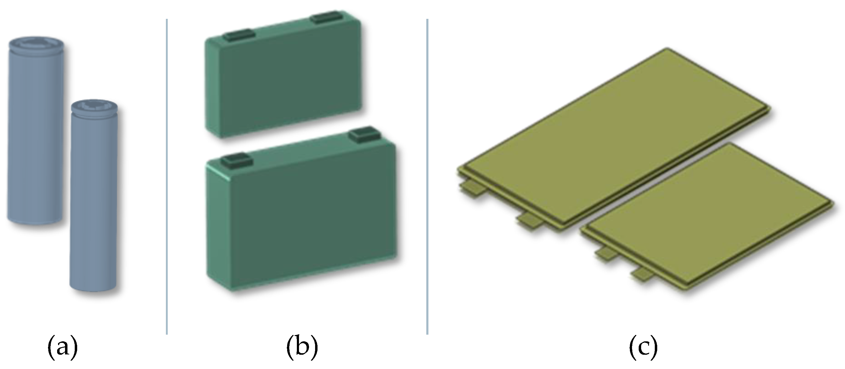
Battery cells represent the core component of EVBs. Three cell formats are commonly used in the automotive industry: Cylindrical, pouch, and prismatic (see
Figure 1). The main difference between the cell formats lies in the design of the cell casing and the arrangement of the cathode, anode, and separators. Prismatic and cylindrical cells are packaged in a hard case, usually made of aluminum or stainless steel. Pouch cells are packaged in multilayer aluminum composite foils. Cylindrical cells contain electrode webs wound with separators to form a jelly roll. Prismatic cells utilize flat jelly rolls or stacked electrodes. Pouch cells exclusively employ a stacked arrangement [
2,
3,
4].
Nowadays, almost all car manufacturers have electric vehicles in their product portfolio and must push electrification intensively in the coming years. Most OEMs rely on Li-ion technology. This trend will become stronger in the near future, driven by global climate targets and the role of electrification of the transport sector in achieving them [
5]. The transport sector accounts for around 25% of global CO2 emissions [
6]. Legal framework conditions are already being established. In the European Union (EU), for example, new cars and vans registered will be emission-free by 2035 [
7].
Nevertheless, the design of battery systems remains heterogeneous among manufacturers, characterized by many differences, for example, in cooling strategies, pack configurations, and, most notably, the utilization of diverse cell formats. Even many car manufacturers simultaneously utilize different cell formats for their products. For instance, Tesla uses mainly cylindrical cells but also prismatic ones, and Volkswagen utilizes prismatic and pouch cells.
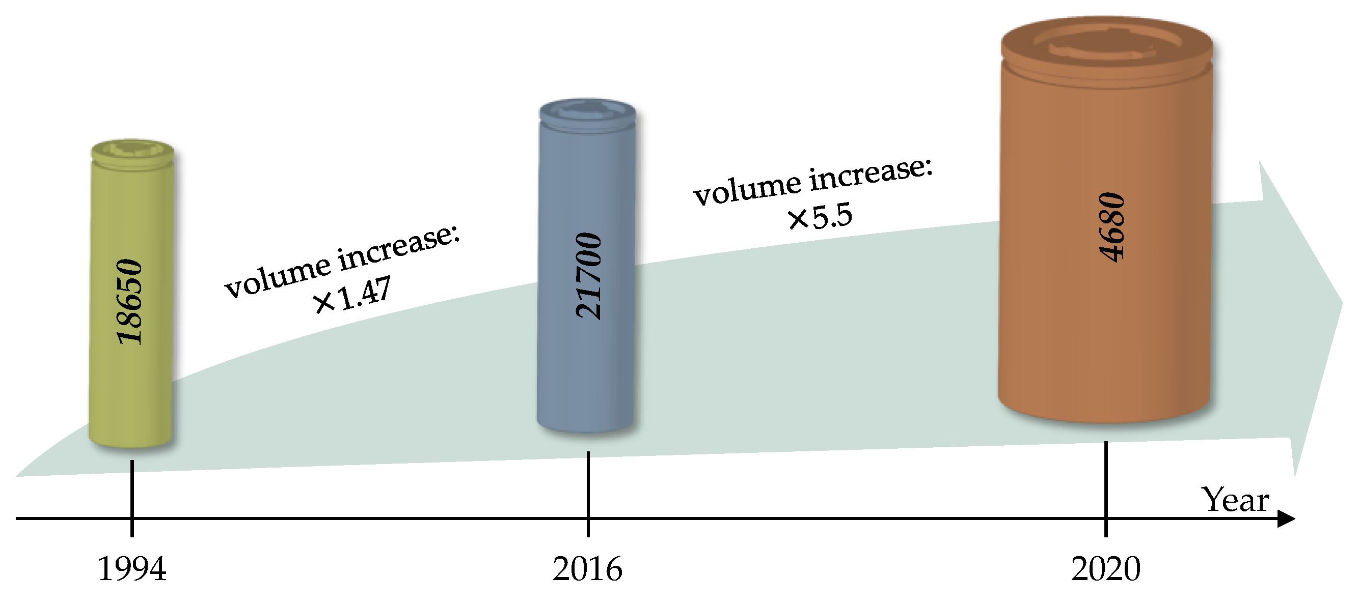
In recent months, cylindrical battery cells have shown huge dynamics in various aspects, especially regarding design and related production technologies. This was mainly triggered by Tesla’s Battery Day 2020, where the company presented its new 4680 cell format and announced plans to use it on a large scale. The 4680 battery cell is 46 mm in diameter and 80 mm in height, making it 5.5 times larger in volume than 21700 cells and eight times larger than 18650 cells. A relative comparison of the dimensions of 4680 cells to the conventional 18650 and 21700 cells is shown in
Figure 2.
Regardless of cell format, battery cells consist of cathodes, anodes, separators, casing, insulation materials, and safety devices [
8]. Battery cell production is divided into three main steps: (i) Electrode production, (ii) cell assembly, and (iii) cell formation and finishing [
3]. While steps (1) and (2) are similar for all cell formats, cell assembly techniques differ significantly [
3].
Cylindrical Li-ion battery cells consist of (i) a jelly roll, a wound composite consisting of a cathode, an anode, and two separators, and (ii) a cell housing consisting of a can and a cap [
9]. Current and heat transport between the jelly roll and the cell housing is traditionally conducted by contacting elements called tabs [
10]. These are metal strips usually made of copper or nickel for contacting the anode and aluminum for contacting the cathode. The tabs are joined to the collector foils by ultrasonic welding. The welding geometry and all other design features, such as location, shape, size, and tabs’ number, differ significantly between the various cell designs and manufacturers [
10]. The classical tab design shows design heterogeneities caused by extended electrical and thermal transport paths [
11,
12]. The limited charge transport mechanisms lead to numerous challenges due to inhomogeneities in various physical properties, such as temperature (the higher the temperature, the greater the degradation [
13]), current density, mechanical stress, state of charge, and particle concentration [
14,
15,
16,
17,
18,
19]. In [
17], Waldmann et al. have shown that using tabs in conventional cells significantly impacts the cyclic lifetime of the cells. In [
20], experimentally using 21700 cells, the authors showed that cell impedance, rate capability, heating behavior, and cycling aging strongly depend on the tab design.
Disadvantages of the classical tab design are safety concerns due to the risk of thermal runaway, lifetime limitation due to accelerated and uneven aging, and efficiency losses due to uneven utilization of electrode materials. In addition, there are production disadvantages due to the use of additional components that require further production steps, cause discontinuities in the production chain, and bring quality challenges. All these factors are arguments against classic jelly roll designs to meet future requirements of car manufacturers: Greater power and energy density, higher safety standards, better rate capability, and low production costs. In addition, all of the above factors prevent the scaling of cylindrical battery cells as an efficient measure for cost reduction at all system levels.
In 2020, Tesla introduced a new jelly roll design used in 4680 cells [
11]. Thereby, an uncoated area at the end faces of the electrode strips is structured with a laser in order that several foil tabs can be cut out of the electrode collector foils. These are then pre-bent by a defined angle immediately before the winding process and finally folded over afterward. On the one hand, this design solves the homogeneity problems, but on the other hand, it requires additional complex processes in production. In addition, coating technology has further challenges in avoiding short circuits within the cell.
Cylindrical battery cells are becoming increasingly popular in the automotive industry. Not only Tesla, but also many car manufacturers are announcing their plans to use them widely. A prominent example is BMW, which has used prismatic cells. However, the company recently announced the launch of its new electric vehicle platform called “Neue Klasse”, which will be based on cylindrical cells with a uniform diameter of 46 mm and two different heights [
21].
Motivated by this trend, this paper analyzes cylindrical battery cells by examining nineteen cells from five manufacturers in four formats (18650, 20700, 21700, and 4680). Our study provides a comprehensive overview of the design principles for cylindrical battery cells. To the best of our knowledge, this is the first scientific publication providing a generic overview of designing cylindrical battery cells. The properties of cells, such as energy density, impedance, and thermal behavior, are studied. Furthermore, we present and discuss production technologies for the format and design flexible production of Li-ion cylindrical battery cells. Thereby, we focus on jelly roll manufacturing as a central and critical process in cell assembling.
3. Results and Discussion
3.1. Generic Overview of Designing Cylindrical Li-Ion Battery Cells
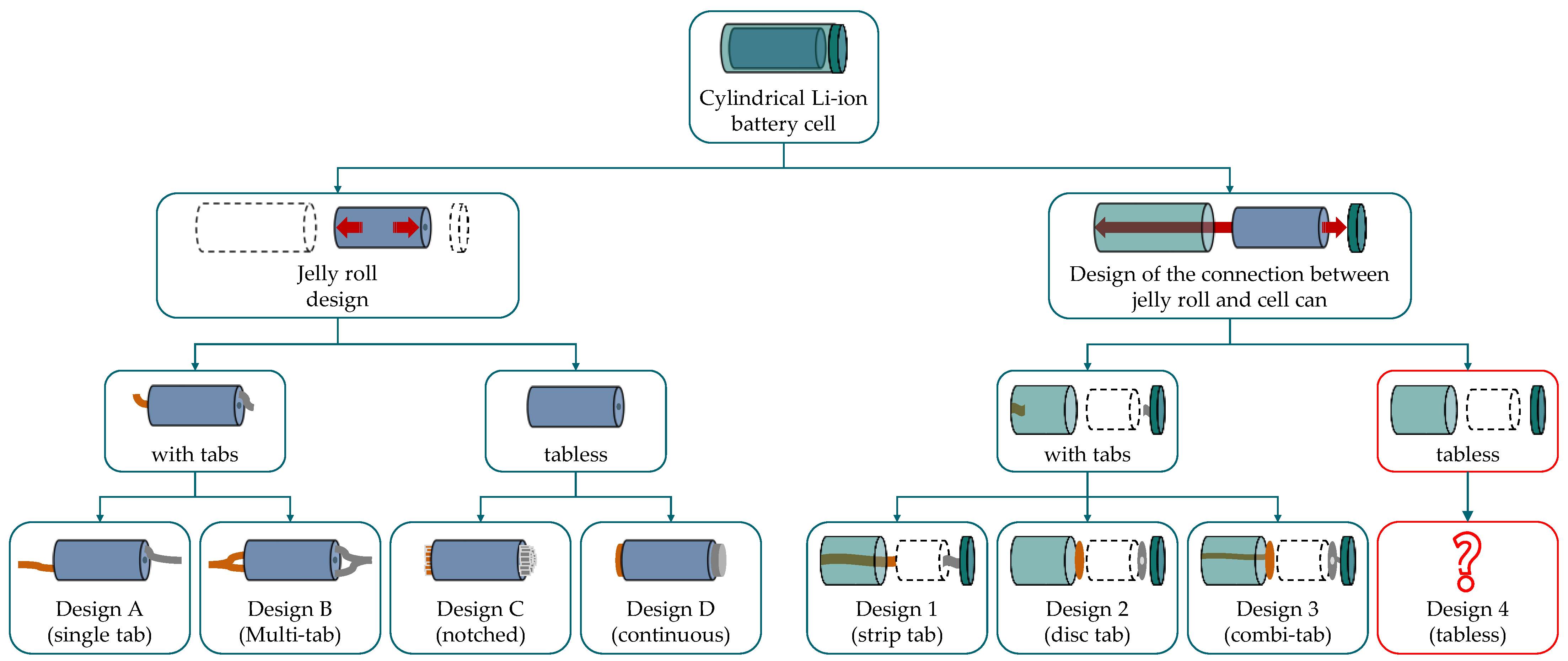
In addition to the design of the electrodes and the separators, two critical functions for efficient and safe Li-ion battery cell operation are (1) current and heat transfer between electrodes and jelly roll front sides and (2) transfer of current and heat between jelly roll front sides and cell casing. We use these two functions as an approach to describe the design principles of cylindrical battery cells generically; see
Figure 4. The jelly roll design determines the first function, while the connection between the jelly roll and cell housing determines the second.
Function 1: Two types of jelly roll designs can be distinguished: With tabs and tabless. Jelly rolls with tabs can be realized with a single tab (Design A) or several tabs in a multi-tab design (Design B). Tabless jelly rolls can be achieved in notched (Design C) or continuous (Design D) designs.
Function 2: For the connection of the jelly roll to the housing, the following options are possible: (i) The outstanding tabs are welded at the bottom and the cover (Design 1), (ii) plate-shaped current collectors are welded on the front sides of the jelly roll. The plate is then connected directly to the cell housing (Design 2), and (iii) plate-shaped plates are extended with strip tabs, which are then connected to the cell housing (Design 3). Two designs are possible for Design 3: (a) Outstanding classical tabs from the jelly roll are folded around the tab plate, and subsequently welded on, resulting in a B-3 design, or (b) a plate tab is welded to the jelly roll front face. This results in a C-3 or D-3 design.
To the best of our knowledge, the following cell designs are available in the current state of the art: A-1, B-1, B-3, C-2, and D-3. Examples of these designs are:
According to our generic representation, the Tesla design is not fully tabless since only the jelly roll design is engineered in a tabless manner. Furthermore, while the Tesla design significantly minimizes inhomogeneities in cylindrical Li-ion cells, it does not eliminate them since at least 25% of the electrodes are not connected to the tab plate. More information on the Tesla design is presented in
Section 3.2.2.
A fully tabless design can be implemented in a C-4 or a D-4 design. Currently, no available cells in the market are fully tabless designed. In a tabless design, both functions (Function 1 and Function 2) are performed tabless by connecting the jelly roll directly to the cell housing, which is not the case in the present cell design of 4680 (Generation 1).
3.2. Jelly Roll Design
3.2.1. Geometry
Key quality parameters for a jelly roll are the winding geometry, alignment, and overhang at the front faces. In the following, these parameters will be discussed using thickness measurements in the wound state through CT analyses, the unwound state after opening the cells, and subsequent verification with analytical calculations using the Archimedean spiral.
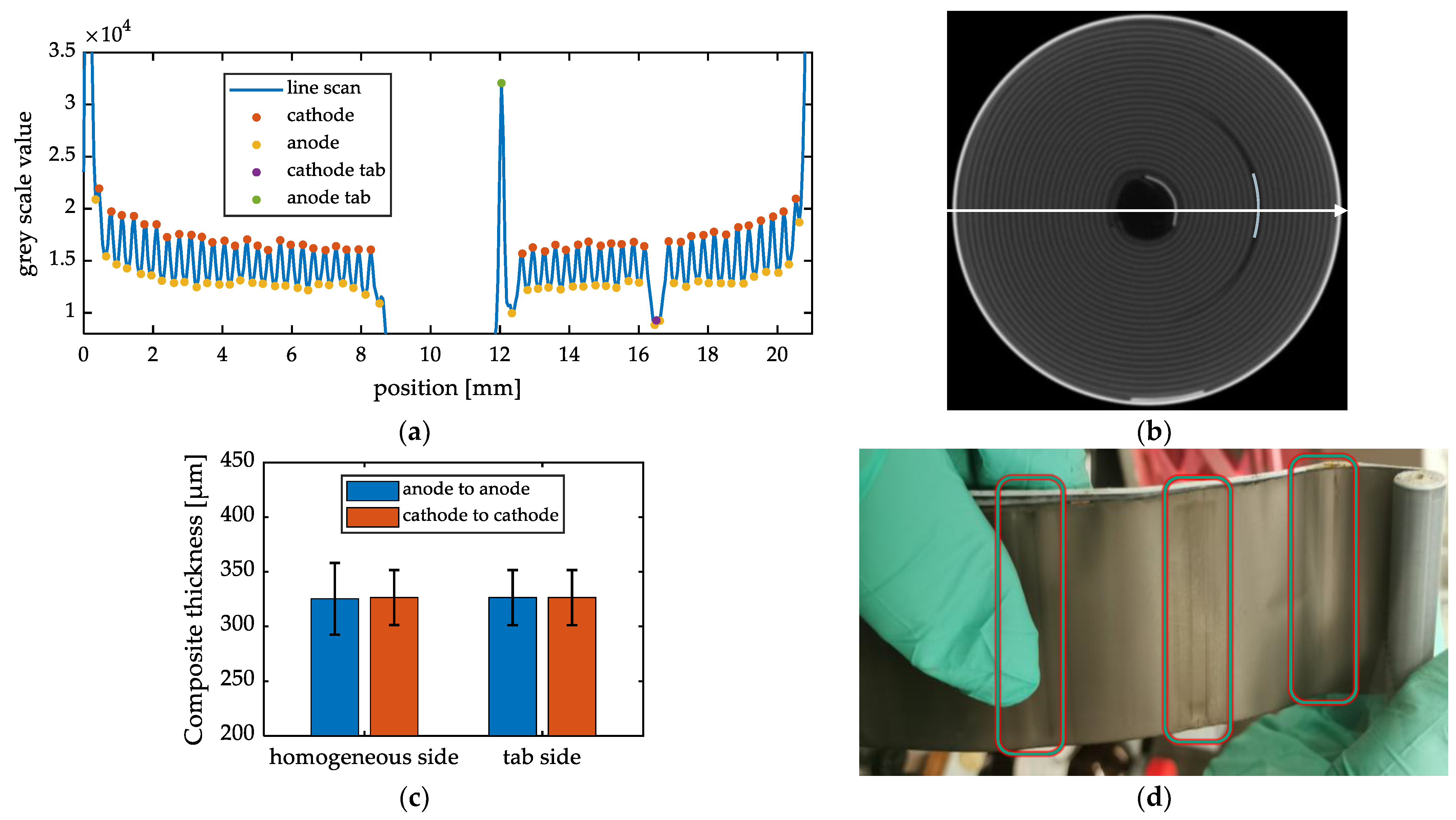
Figure 5a shows a wavelength analysis using the INR21700-M50LT battery cell. The gray values along the marked line perpendicular to an anode tab and a cathode tab were analyzed (see
Figure 5b). Subsequently, the distances between the peaks of the gray values were evaluated. The distances from one anode to the subsequent one after exactly one winding can be determined. The same applies to the cathode windings. In this way, the composite thickness
t within the jelly roll can be determined using two different methods without opening the cell (see Equation (1)). The proof hereof is derived below.
where
ts is the separator thickness,
tc is the cathode coating thickness,
tA is the anode coating thickness,
tAl is the aluminum current collector thickness, and
tCu is the copper current collector thickness.
The wavelength evaluation was conducted on two sides: The tab-free side (homogeneous side) and the side with two tabs (inhomogeneous side). The mean composite thickness and standard deviation on the homogeneous side are 325.23 μm ± 32.8 μm (anode-to-anode) and 326.37 μm ± 25.15 μm (cathode-to-cathode). The inhomogeneous side has a mean composite thickness and standard deviation of 326.34 μm ± 25.24 μm and 326.33 μm ± 25.22 μm, respectively (see
Figure 5c). The mean thickness values for both sides were very similar, resulting in an overall mean thickness of 326 μm. The standard deviations are more significant than the coating tolerances of electrodes, typically varying between ±2 μm and ±5 μm, according to experts. These differences can be explained by three factors: (i) The tab influence, as the tabs compress the coating and cause mechanical damage visible in several successive windings (see
Figure 5d). (ii) Measurement errors due to the resolution. (iii) The coating tolerances for the studied cell are unknown.
After determining the composite thickness t in the rolled state by evaluating the CT measurements, the cell was opened, and the different components of the composite were measured individually. The following values were obtained as an average by recording five values in randomly selected positions: ts = 11 μm, t1 = 52.5 μm, ta = 82.5 μm, tAl = 25 μm, and tCu = 10 μm. This results in a composite thickness of 327 μm. The difference between CT and post-mortem measurement is less than 0.3%. Therefore, the radius in the wound state increases between winding n and winding n+1 by exactly the composite thickness t, and thus the jelly roll can be approximated very well with the Archimedean spiral.
Along the marked line in the CT image, 24.5 windings with the entire composite (1× double-side coated anode, 1× double-side coated cathode, and two separators) are identified. Using the corresponding inner and outer diameters of 4 mm and 19.9 mm measured in the CT image and the analytical Archimedean spiral equation (see Equations (2)–(4)), 24.4 windings are calculated. The deviation between measurement and analytical verification is less than 0.4%.
3.2.2. Tab Design
The tab design is particularly essential in designing cylindrical Li-ion battery cells to avoid inhomogeneities in the battery cell, mainly due to extended thermal and electrical transport paths. The tab design becomes increasingly critical the larger the diameter of the winding.
An increase in the jelly roll diameter by a factor of n leads to an increase in electrode length by a factor of n2. We have checked this correlation for three different composite thicknesses (200 μm, 300 μm, and 400 μm) for diameters between 20 mm and 200 mm. The exact data are provided in
Supplementary Materials SM3. This over-proportional increase in electrode length makes scaling cylindrical batteries a complex engineering task, particularly concerning the diameter.
For the cells examined in this paper, A (8 cells), B (10 cells), and C (one cell) jelly roll designs were identified (see
Figure 4). These were integrated into the battery housing using the configurations A-1, B-1, B-2, and C-2. Tab pictures can be found in the
Supplementary Materials SM4 for all cells.
Design C-2: This design corresponds to the first-generation Tesla design for 4680 cells; see
Figure 8 and
Figure 9.
Figure 6.
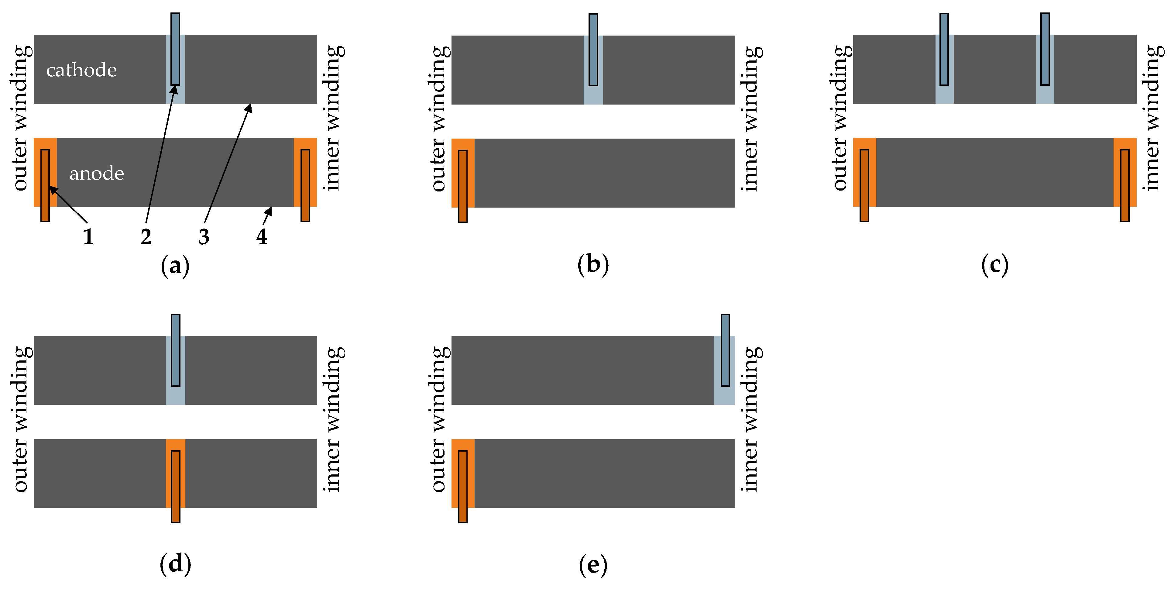
Identified tab designs (1—Ni/Cu tab; 2—Al tab; 3—cathode; 4—anode): (a) Tab design in Sony/Murata US18650VTC4, Sony/Murata US18650VTC6, Samsung INR18650-25R, Sanyo 18650RX, LG INR18650HG2L, LG ICR18650-HE2, Panasonic NCR20700B, and LG INR21700-M50LT; (b) Tab design in Samsung INR18650 35E, Samsung ICR18650 22P, Panasonic NCR18650B, Samsung INR21700 33J, and LG Chem INR21700 M50T (c) tab design in Sanyo NCR2070C and Sony US21700VTC6A; (d) tab design in Samsung INR21700-40T and Samsung INR21700-50E; (e) tab design in LG INR18650MJ1.
Figure 6.
Identified tab designs (1—Ni/Cu tab; 2—Al tab; 3—cathode; 4—anode): (a) Tab design in Sony/Murata US18650VTC4, Sony/Murata US18650VTC6, Samsung INR18650-25R, Sanyo 18650RX, LG INR18650HG2L, LG ICR18650-HE2, Panasonic NCR20700B, and LG INR21700-M50LT; (b) Tab design in Samsung INR18650 35E, Samsung ICR18650 22P, Panasonic NCR18650B, Samsung INR21700 33J, and LG Chem INR21700 M50T (c) tab design in Sanyo NCR2070C and Sony US21700VTC6A; (d) tab design in Samsung INR21700-40T and Samsung INR21700-50E; (e) tab design in LG INR18650MJ1.
Figure 7.
Tab design of Panasonic NCR2070C: (1) Aluminum tab 1; (2) current collector; (3) aluminum tab 2; (4) nickel tab 1; (5) nickel tab 2; (6) arrangement of the tabs on the electrodes.
Figure 7.
Tab design of Panasonic NCR2070C: (1) Aluminum tab 1; (2) current collector; (3) aluminum tab 2; (4) nickel tab 1; (5) nickel tab 2; (6) arrangement of the tabs on the electrodes.
Figure 8.
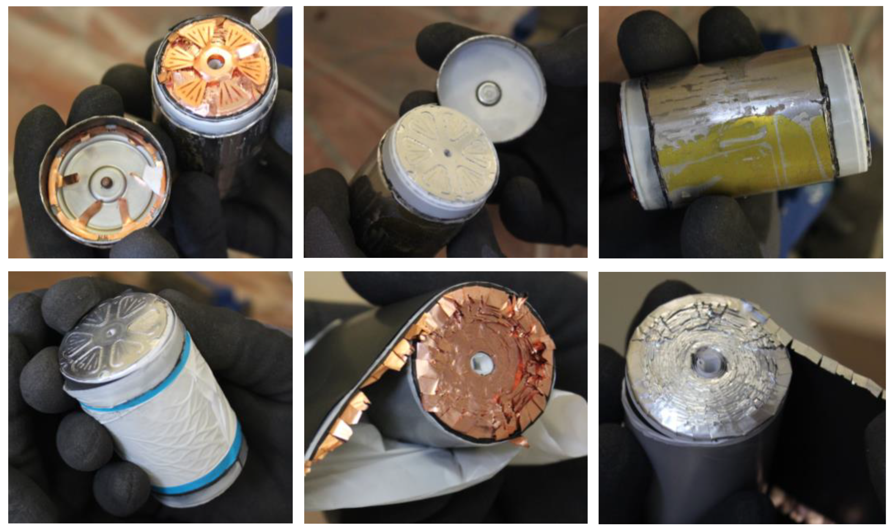
Opening the 4680 battery cell.
Figure 8.
Opening the 4680 battery cell.
Figure 9.
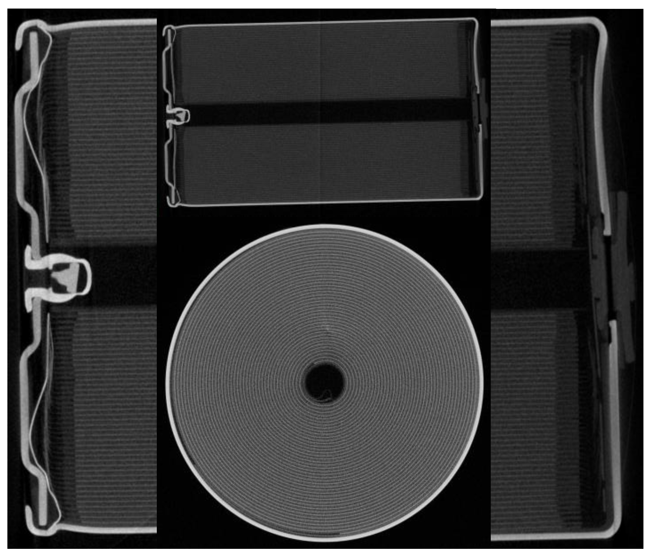
CT images of the 4680 battery cell.
Figure 9.
CT images of the 4680 battery cell.
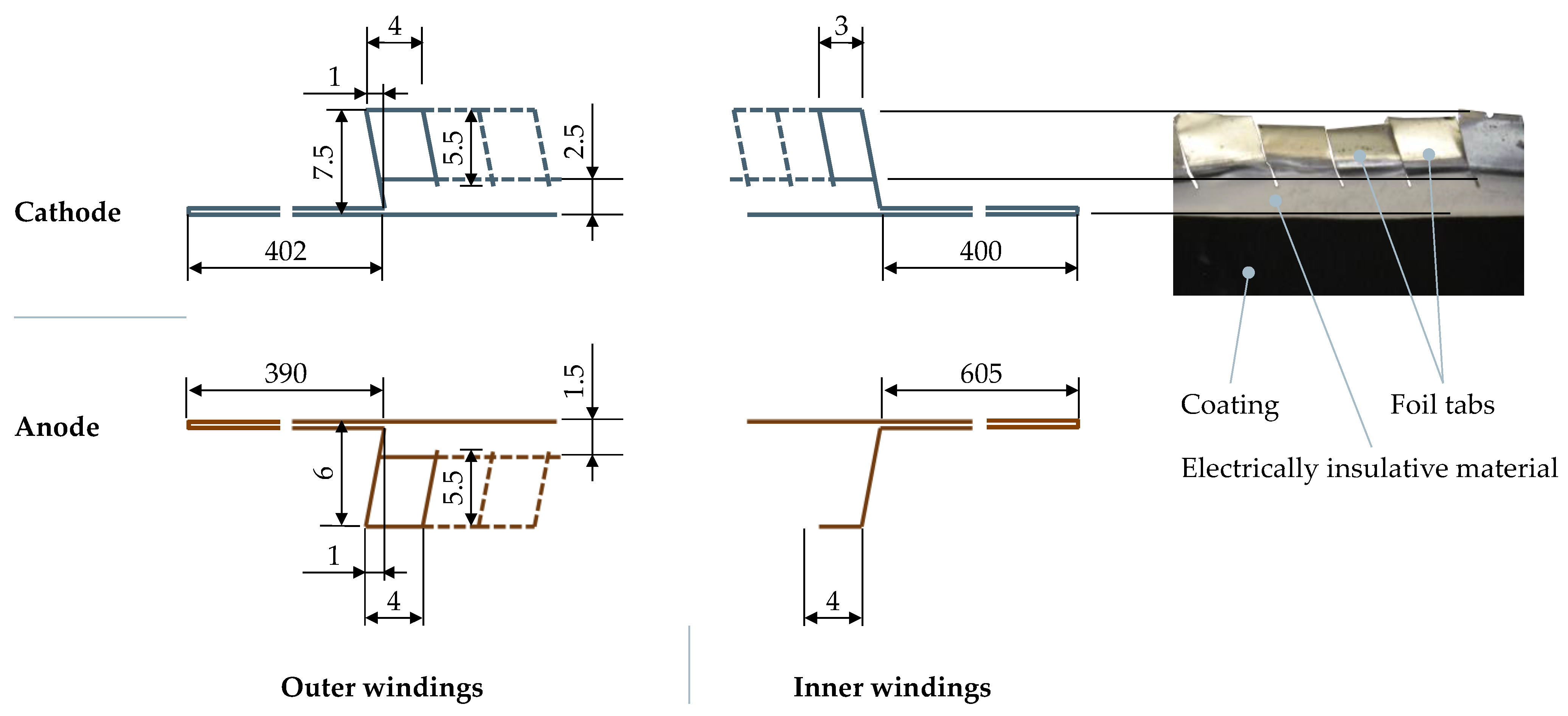
When the jelly roll is unwound, the notched region of the cathode starts from 402 mm from the beginning of the cathode and extends up to 400 mm before the end of the cathode, meaning that 25% of the total cathode length of 3180 mm is not notched. Similarly, the notched tabs of the anode begin at 390 mm and continue until 605 mm before the end of the anode, resulting in 30% of the total anode length of 3370 mm being not notched. These areas remain not notched since they are necessary to realize a flexible structure of the tab plate. A flexible structure enables the decoupling of the joints between the jelly roll and the current collector (tab plate) and between the current collector and the housing. Decoupling is necessary to protect the sensitive laser beam weld between the jelly roll and the tab plate from damage during production and the use phase. During assembling, the tab plates are subjected to high mechanical stress, for example, when sealing the cell in a crimping process, in which the plate is clamped and connected to the negative terminal. During the use phase, the flexible structure can compensate for possible volume expansions and protect the laser beam welds from mechanical stresses, such as those caused by vibration.
3.3. Cell Properties
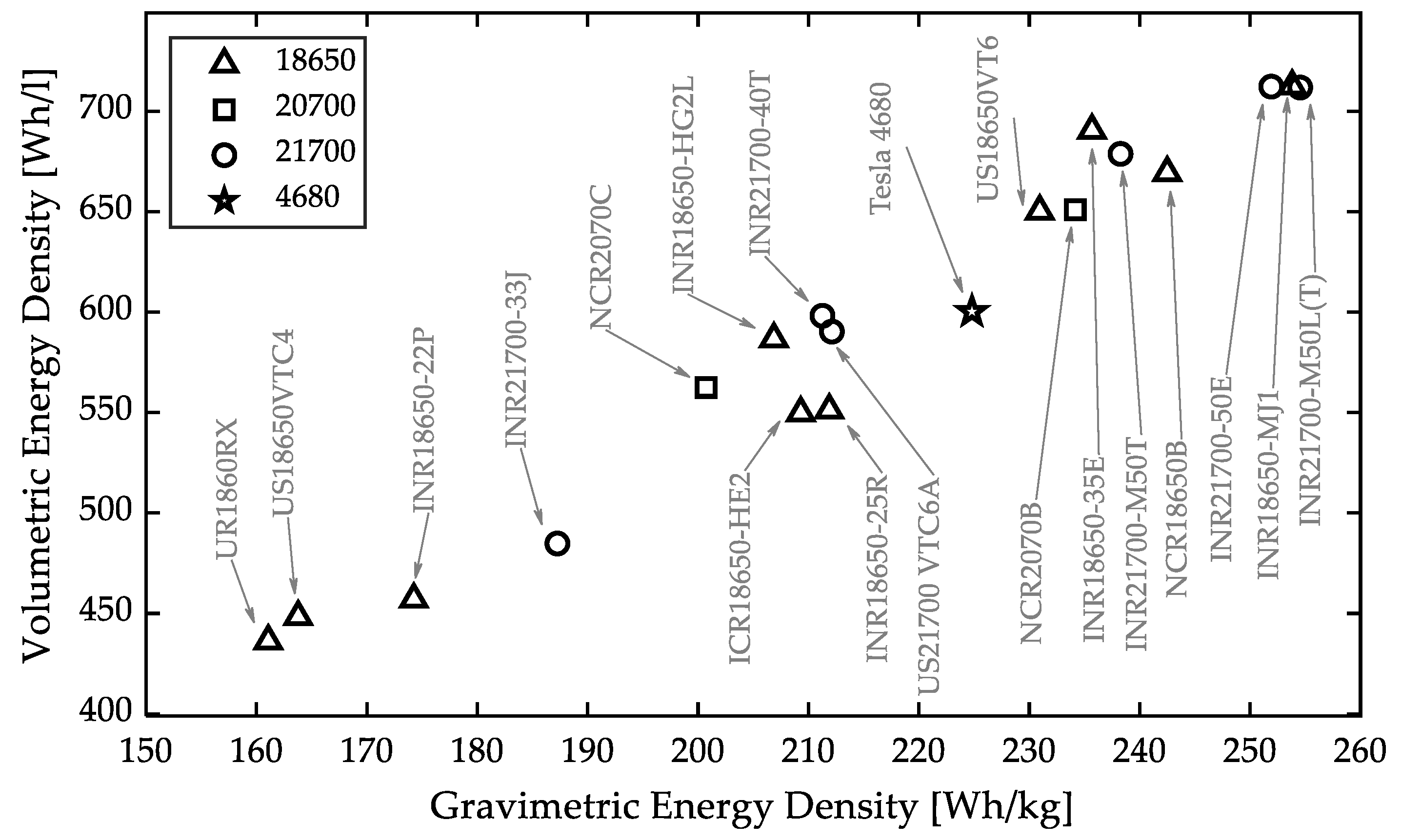
3.3.1. Energy Density
Figure 10 shows the calculated energy densities from the 19 cells considered. The gravimetric energy density varies between 161 Wh/kg and 254.5 Wh/kg, and the volumetric energy density is between 436.25 Wh/L and 712.5 Wh/L. The correlation between gravimetric and volumetric energy densities is linear (R
2 = 0.97). It can be observed that the energy density of 21700 cells (average values: 264.5 Wh/kg and 629.4 Wh/L) is higher than the density of 18650 cells (average values: 192.5 Wh/kg and 575.2 Wh/L). However, the energy density of the 4680 battery cell of 224.8 Wh/kg is relatively small compared to many cells studied in this paper, even though the electrode coating of the electrodes is significantly larger than all other cells. The 4680 cell has an anode thickness of approximately 258 μm and a cathode thickness of 170 μm. Both values were determined as the average of 10 measured values in random positions along the electrodes. The average thickness for all other cells is 144 μm for the anode and 128 μm for the cathode.
The energy density measured may differ from the manufacturer’s specifications due to the unified testing conditions. For example, for the NCR2070C cell, an energy density of 569 Wh/L/214 Wh/kg is specified in the datasheet. However, we measured 562.52 Wh/L/200.72 Wh/kg. This corresponds to a deviation of −1.1%/−6.2%.
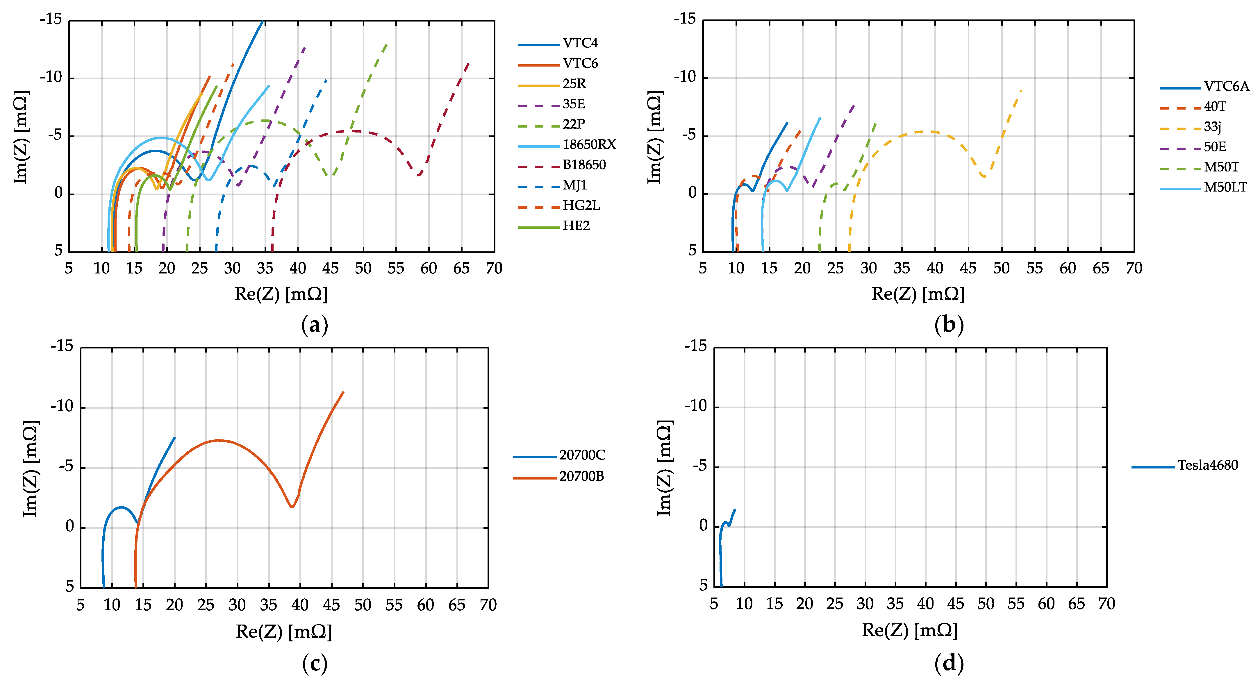
3.3.2. Cell Resistance
In general, the impedance decreases with increasing the form factor. This can be explained by the cathode surface area. In [
23], Quinn et al. showed that the impedance is indirectly proportional to the cathode surface area. Therefore, a direct comparison between all investigated cells is not easily possible.
Figure 11a shows the impedance of all 18650 cells tested. If the tab design is considered for comparison, two groups can be identified: The first group, presented in dashed lines, has two tabs on the anode side and shows low resistance. Four of the five cells exhibit comparable ohmic resistance, ranging between 11.5 μΩ and 11.7 μΩ. However, one of the cells shows a slight deviation from the group, with a higher resistance of 15.7 μΩ. Cells with a single tab design show an ohmic resistance between 14.7 μΩ and 36.7 μΩ.
Battery cells in the 21700 cell format behave similarly; see
Figure 11b. Two cells have a multi-tab design and show low ohmic resistance. The VTC6A cell has a tab design B-1 on both the anode and cathode side, resulting in a minimum resistance of 9.9 μΩ.
The lowest ohmic resistance in cells with a classic tab design is found in Panasonic’s 20700C cell with a B-3 cell design; see
Figure 11c. Details of the B-3 design used are shown in
Figure 7. The impedance of the quasi-tabless 4680 battery cells shows the lowest impedance. The ohmic resistance is 6.3 μΩ; see
Figure 11d.
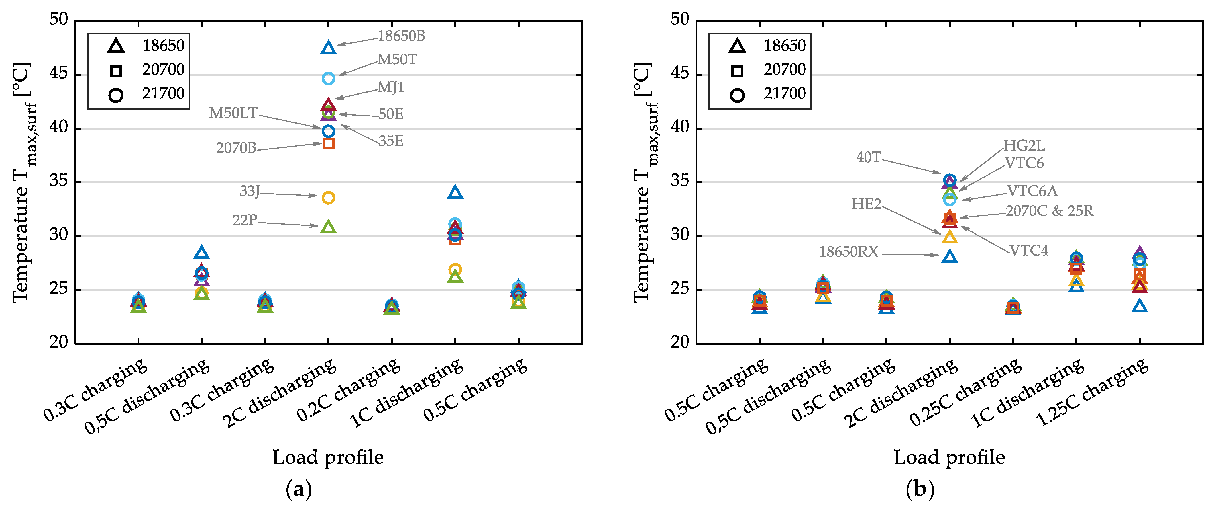
3.3.3. Thermal Behavior
Figure 12 shows the temperature at the surface for both groups at different charge and discharge C rates. At 2 C discharge rates, the substantial differences in the thermal properties of the battery cells examined are demonstrated. The temperature rise for 18650 cells varies significantly between 5 °C and 24 °C and between 10 °C and 24 °C for 21700 cells.
In the following, we only consider the 0.5 C discharge to compare conventionally designed cells with the 4680 Tesla design.
We conducted charging and discharging tests on the 4680 cells using a CCCV profile, as shown in
Figure 13a. The discharge capacity we obtained was 22.2 Ah, indicating that a current of 10 A approximates 0.5 C (see
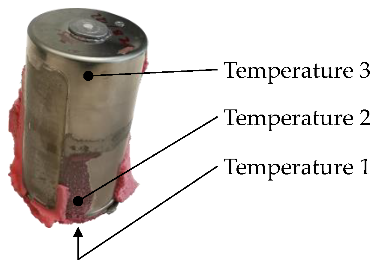
Figure 13b). The temperature evolution of the three sensors mounted on the cell surface is presented in
Figure 13a. The positions of the sensors are shown in
Figure A1 in
Appendix A.
At room temperature inside the climate chamber, the outer surface of the 18650 and 21700 cells with classical tab design experienced a temperature increase between 1.2 °C and 5.3 °C. In contrast, the 4680 cell showed a temperature increase of 8.2 °C, indicating that the quasi-tabless is not sufficient to compensate for the poor surface-to-volume ratio of large-scale cell formats. 4680 cells have only half the ratio of 18650 cells. In addition, we have demonstrated in
Section 3.2.2 that more than 25% of the electrodes are not notched, resulting in extended thermal transport paths.
- b.
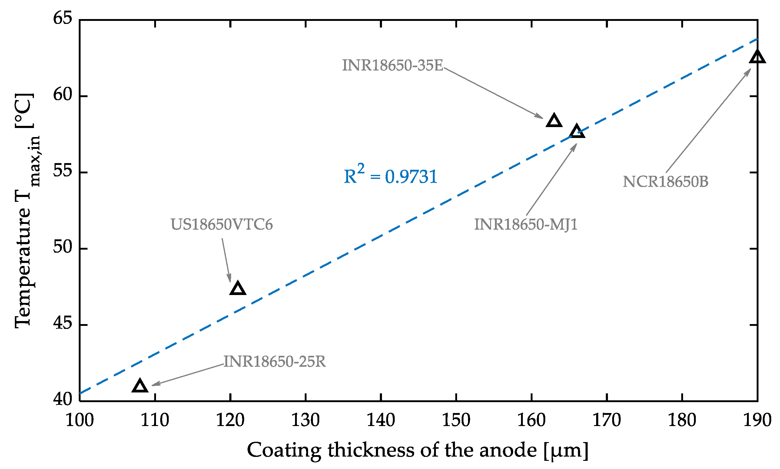
Internal temperature
Only five of the eighteen prepared cells are suitable for evaluating the internal temperature. In these cells, the electrical resistance did not increase after the sensor integration, and the surface temperature was comparable to the surface temperature of reference cells. The temperature inside is 30% to 40% higher than the temperature on the surface when applying a discharge current of 2 C. The surface and inside temperatures are listed in
Table 3.
Figure 14 depicts the linear correlation between the internal temperature and the anode thickness, with an R
2 value of 0.97. This correlation was also identified in [
23]. However, this relationship is invalid when considering gravimetric energy density, as evidenced by the lower R
2 value of 0.7. The energy densities are presented in
Section 3.3.1.
3.4. Jelly Roll Manufacturing
Li-ion battery cell manufacturing consists of three main steps: (1) Electrode fabrication, (2) cell assembly, and (3) cell formation and aging. In this section, we focus on the second step since changes in tab design present new challenges in cell assembly. Cell assembly begins with manufacturing the jelly roll as a central component of a Li-ion battery cell. The jelly roll is inserted into a cell housing and contacted on the anode and cathode sides. After electrolyte filling, the cell is sealed.
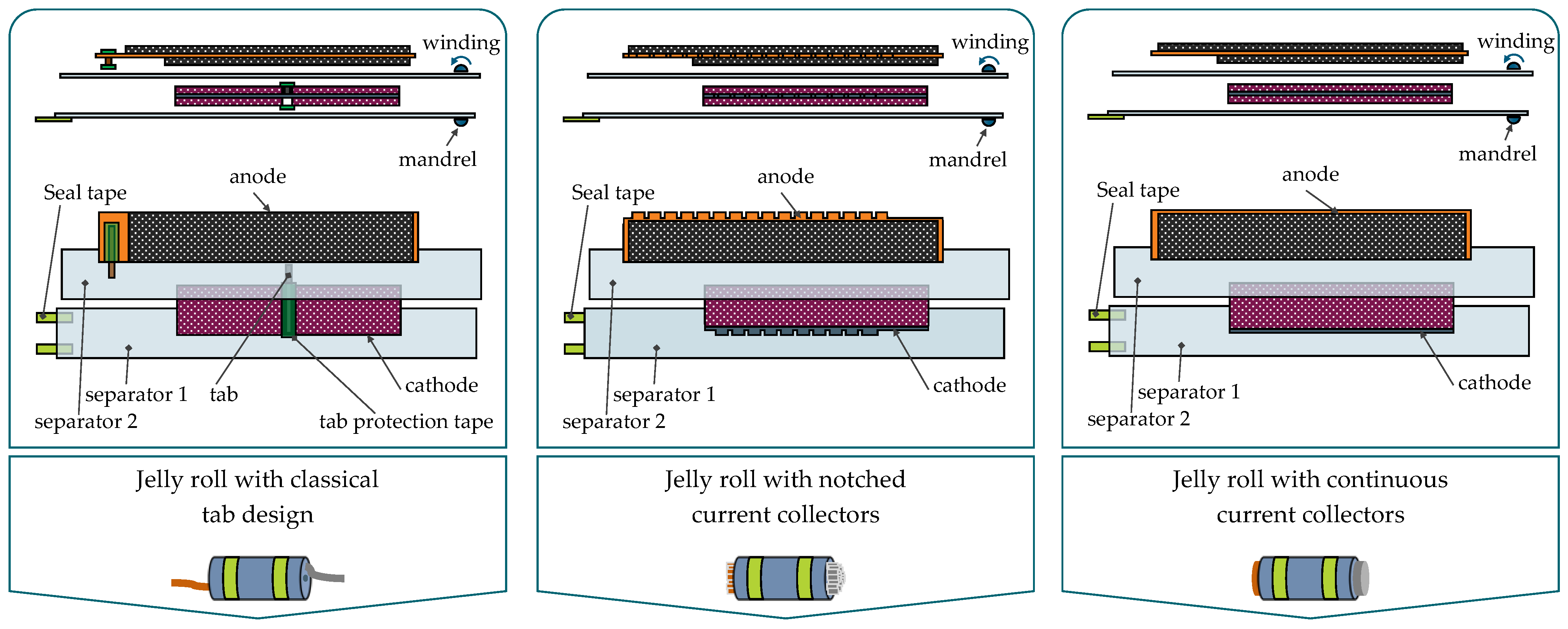
Jelly rolls for cylindrical Li-ion battery cells differ in two basic designs: (1) With tabs (Design A and Design B) and tabless (Design C and Design D). The main process in jelly roll production is the winding process. This process, compared to stacking, is simple and continuous, making the production of cylindrical battery cells cost-effective, robust, and relatively easy to scale. We found out from interviews with equipment manufacturers that the processing time for an electrode length of 1 m is about 1.25 s and that an electrode length of 5 m can be wound in less than 3 s. A cell composite consisting of two separators, a cathode, and an anode, is wound. Thereby, the electrode webs are preprocessed differently, depending on the design.
The winding process itself is similar for all designs. Immediately before winding, appropriate edge alignment and positioning solutions are provided to ensure the dimensional accuracy of the jelly roll by minimizing the telescope effect during winding and to prevent short circuits within the cell. The following geometric dimensions are important quality parameters in the production of jelly rolls. The value ranges for the cell studied in this paper are shown in
Table 4. Cell-specific values are provided in the
Supplementary Materials SM5.
Highest anode to lowest cathode (P1);
Lowest anode to highest cathode (P2);
Lowest cathode to highest cathode (P3);
Overhang anode to cathode, max (P4);
Overhang anode to cathode, min (P5).
Table 4.
Geometrical parameters.
Table 4.
Geometrical parameters.
| Parameter [mm] | Negative Terminal | Positive Terminal |
|---|
| P1 | 0.20–0.85 | 0.15–0.75 |
| P2 | 0.10–0.60 | 0.20–0.45 |
| P3 | 0.10–0.60 | 0.10–0.45 |
| P4 | 0.45–1.15 | 0.40–1.05 |
| P5 | 0.30–0.70 | 0.25–0.90 |
A further important quality parameter in the winding process is web tension of the electrode and separator webs.
In jelly roll manufacturing, three winding technologies can be identified to represent current and future format and design flexibility; see
Figure 15. The first technology is needed to manufacture jelly rolls in Design A or B using the following steps:
Insulate the tabs at the jelly roll exit position with insulation tape. Only the aluminum tabs are insulated since the anode is always higher than the cathode.
Ultrasonic welding of the tabs to the uncoated area of the electrode webs. Here, an intermitted coating is needed.
Covering the tapes with protective tape. We observed that the tabs are protected differently in the cells we studied. In some cases, all the tabs are covered from both sides. In other cases, the tabs are protected only from one side or are even completely unprotected.
Gripping the separators and starting the winding process without electrodes.
Insertion of the anode and winding without cathode.
Insertion of the cathode.
Cutting the cathode web and further winding the remaining jelly roll components.
Cutting the anode and further winding the separators.
Cutting the separators.
Fixing the jelly roll with one or several seal tapes or using a heat sealing process.
Jelly roll testing. Possible tests are measuring the height, diameter, overhang between anode and cathode, and impedance.
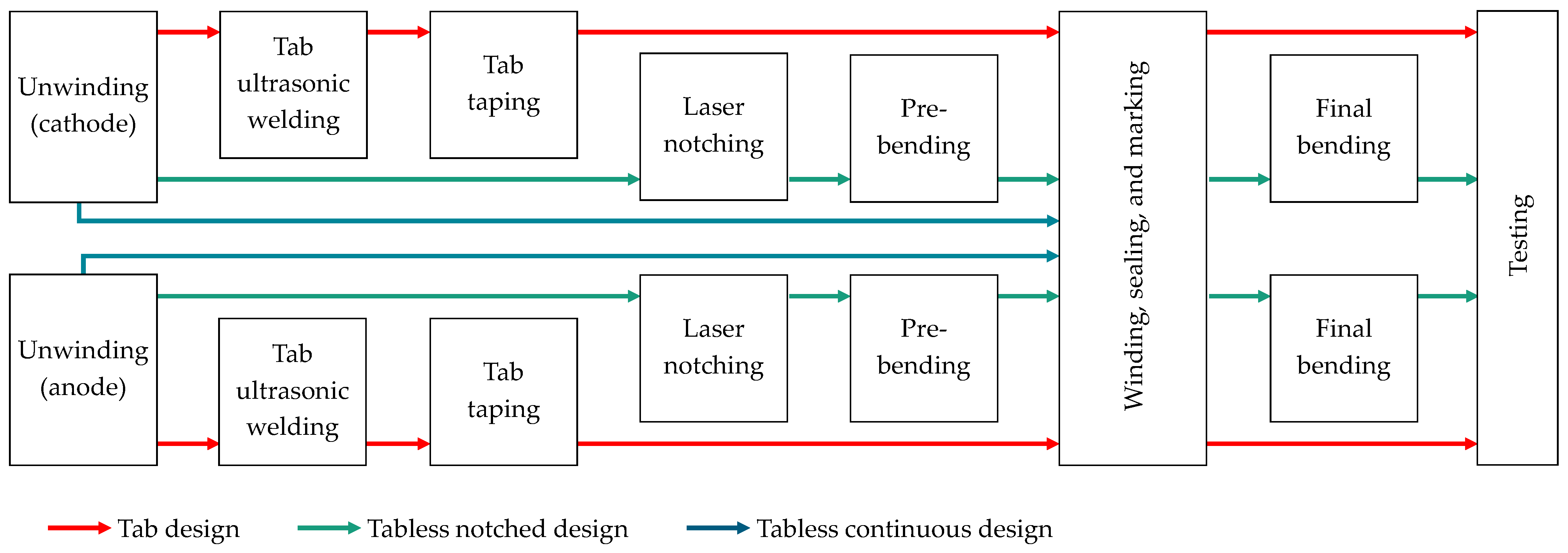
Figure 15.
Jelly roll manufacturing—winding tasks.
Figure 15.
Jelly roll manufacturing—winding tasks.
Steps 4 to 11 are also required to manufacture jelly rolls with notched current collectors (Design C). In addition, there are preparatory processes for the electrode webs involving laser cutting foil tabs in the uncoated area. The applied notching geometry in the investigated Tesla cell is shown in
Figure 16. The main challenges during the notching process are:
Figure 16.
Notching geometry in Tesla 4680.
Figure 16.
Notching geometry in Tesla 4680.
Another process in the manufacturing of Design B is the bending of the tab foils. In preliminary tests, we could perform the bending process as follows: Immediately before winding, the tabs are pre-bent with an angle of 30° to 45°. After winding, they are finally bent using a single tool that moves continuously perpendicular to the rotating jelly roll and progressively bends the foil tabs to an angle of 90°. The main process parameters are the rotation speed of the jelly roll and the feed speed and surface properties of the bending tool.
From a production point of view, Design C (jelly rolls with continuous current collectors) is the easiest to manufacture. The manufacturing involves only a winding task that can be realized using steps 4 to 11 only. There are no previous or subsequent processes.
Figure 17 shows a production layout for a format and design-flexible winding machine. The material flows for the three designs shown are illustrated. In addition, this machine allows for six combination designs, which consist of the basic designs shown in
Figure 15. Thereby, the positive and negative terminals can be completely differently designed, as the production modules can be flexibly activated depending on the product recipe. We have developed this machine with an industrial partner, and it is currently being installed in our laboratory. The main dimensions of the machine are
l ×
b ×
h = 8 m × 1.4 m × 2.14 m. It will enable us to experimentally investigate the tab design’s influence on cell performance and production costs.
4. Conclusions
This work investigated 19 cylindrical Li-ion battery cells from four cell manufacturers in four formats (18650, 20700, 21700, and 4680). Design features, such as tab design and quality parameters, such as manufacturing tolerances were recorded using CT and post-mortem analyses, allowing us to describe cylindrical cells comprehensively and derive a general definition for tabless designs. A tabless design must enable a current and heat transfer between electrodes and jelly roll front sides and between jelly roll front sides and cell casing without using any additional metal parts. It is shown that based on our description of cylindrical cells, the Tesla 4680 is quasi-tabless since plate-shaped tabs are used, and the electrodes are not fully notched. We found that 25% of the cathode and 30% of the anode are not notched, resulting in long electrical and thermal transport paths. The tab design was analyzed in detail for all investigated cells. The considered cell properties (energy density, impedance, and temperature on the surface and inside the jelly roll) show large differences between all cells. The 4680 cell from Tesla has an innovative design. However, it shows no significant advantages in energy density and heating behavior compared to 18650, 20700, and 21700 cells, which have a classic tab design. We strongly believe that Tesla has been conservative with the first generation and has not exploited the potential of 4680. Other factors, such as safety issues, production techniques, and fast time to market should have played a significant role in Generation 1 of 4680. Finally, we have described the production processes for format and design-flexible jelly roll production and presented the material flow in a flexible winding machine. This is the solution we are currently building in our laboratory. Flexible production will bring competitive advantages in the future, as the application strongly determines cell design.


 ,
, 


