1. Introduction
The increasingly stringent worldwide regulations on greenhouse gas (GHG) emissions call for decarbonization in all sectors. Among others, the transportation sector is undergoing a drastic change in phasing out fossil-fuel-based energy resources. The maritime transport of goods accounts for more than 70% of the world trade in terms of value and 80% in terms of volume [
1,
2]. The International Marine Organization (IMO) suggested that if the situation remains unchanged, the maritime transportation sector will be responsible for 12–18% of global carbon dioxide (CO
2) emissions by 2050 [
3,
4].
In this regard, it is of vital importance to substantially reduce the environmental im-pact of maritime transportation. Since the year 1983, the importance of reducing the vessels’ GHG emission and the energy losses have come to the forefront [
5]. Nevertheless, it was not until the year 2011, with the 62nd session of the IMO’s Maritime Environmental Protection Committee (MEPC), that the maritime industry committed to adopt mandatory measures to reduce GHG emissions from both new buildings and existing ships [
6].
Since then, actions have been taken to identify and improve the shipboard energy performances, including but not limited to: hull shapes optimization, the integration of energy-saving devices, architectural optimization, adoption of lightweight structures and materials, as well as fuel efficiency improvement for ships in service and installation. Recently, with the advancement and prevalence of energy storage systems (ESSs), concrete measures have been taken to integrate ESSs into ships, leading to fully electrified or hybrid marine power system configurations [
3,
7]. Nevertheless, a monotype topology based on a single battery cell chemistry is the current technology for battery electric and hybrid electric vessels, which is often designed to meet the critical requirements of both high-energy missions (e.g., for maintaining cruising speed) and high-power peaks (e.g., fast charging and maneuvering) [
8,
9,
10]. Due to the exploitation of batteries to meet these requirements, the battery capacity can decrease greatly over time. Often, the battery pack degradation is compensated by oversizing the battery that leads to high capital costs [
11]. One promising solution is to adopt a hybrid battery topology that downsizes the energy storage system by providing sufficient energy and power to the ship to meet the demands. Moreover, hybrid topology removes the high-current stress factor from the high-energy battery, resulting in a longer lifetime, smaller temperature peaks in the cells, and eliminating the effect of a high depth of discharge (DoD). The advantage of hybrid battery energy storage systems (HBESS) is threefold. First, HBESS can effectively cover the fluctuating load profiles by adjusting the proportion of different types of battery cells in the battery system. Second, the efficiency, reliability, and flexibility of the marine power system is increased due to less exploitation. Finally, the cost of the battery system is significantly reduced by avoiding oversizing [
12].
However, HBESSs have only been investigated in road transport applications and electric grid applications (including charging stations) [
13,
14], while there has been limited explorations in maritime applications [
11,
12]. Although the existing literature, such as [
8,
15,
16], has proposed several hybrid battery energy storage systems (HBESSs), it remains unanalyzed which HBESS has an advantage due to the absence of a generic design and evaluation framework on maritime HBESS.
To the best of the authors’ knowledge, this is the first study presenting a framework that allows the battery system designer to systematically compare different HBESS modular designs on a level playing ground.
More specifically, the contribution of this present study is two-fold:
A generic design and evaluation framework is proposed to ensure that the key design requirements are accounted for in a level playing field for different topologies. In doing so, generalized key component models, such as battery cell models, aging models, dc/dc converter models, and thermal models are established;
Leveraging the generic design guidelines, a baseline BESS and two HBESS modular design topologies are quantitatively evaluated over four key KPI (key performance index) dimensions, namely total battery system cost, total battery system volume, total battery system weight, and total battery system loss.
In comparing the three selected topologies, the design and evaluation results imply that, given the input data and load scenario provided in this study, the module level converter topology outperforms other topologies in terms of costs, energy density, and energy efficiency. Albeit the difference in topologies, especially the hierarchical (i.e., module level or cell level) installation positions of DC/DC converters, battery cells remain the major cost, mass, and volume driver in modular battery system topologies. Therefore, hybridization in battery cell types can reduce the cost and increase the energy density significantly, except for certain critical load scenarios (where the required battery capacities are lower).
The remainder of this article is organized as follows. The modular battery topology design and evaluation framework, as well as the key underlying generic component models are elaborated in
Section 2 and
Section 3, which describe the key design requirements and the input data used in this study, respectively. The results are presented in
Section 4 and discussed further in
Section 5, followed by the conclusion and outlook in
Section 6.
2. Materials and Methods
The generic framework is depicted in
Figure 1. Central to this design framework is the HBESS model (detailed in
Section 2.1) and the optimization algorithm (detailed in
Section 2.2). The optimization is applied to each topology with reference to the operational requirement for different vessels (specified in
Section 3). The output of the optimization is the optimal size of the HBESS, which is used by the evaluation methods (detailed in
Section 2.3) for evaluation against the selected KPIs. For a certain vessel application, the load profile, the specifications of the investigated batteries, and the technical specifications of the topologies (detailed in
Section 3.1) are the input of the optimization. The output of the evaluation method is the cost (including the cost of the cells, power converters/switching devices and cooling system) of the battery pack, together with the weight, volume, and losses of each topology. The lifetime of the battery system is considered as a constraint in the optimization.
2.1. HBESS Model Description
2.1.1. Battery Cell Model
For modelling the battery cell, a basic equivalent circuit model is used, where battery behavior is described using an ideal voltage source, whose purpose is to simulate the battery open-circuit voltage, and a resistor that considers the battery internal resistance due to the electrodes. This modelling approach is a common practice in battery sizing [
15,
17], and it has been experimentally validated in reference [
18]. This study considers two mainstream battery types, high-energy NMC and one high-power LTO cell, for the evaluation of different HBESS topologies. The techno-economic parameters are detailed in
Section 3.
2.1.2. Ageing Model
Due to the difficulty of obtaining the full data of the cells in terms of a lifetime for cycle and calendar aging, two critical assumptions are adopted. First, the cycle life of the cells is estimated using a linear approximation based on the available data of the cycle life of the reference batteries. Second, the calendar aging is assumed to be 1% per year for both batteries when the system is not in use (standstill).
2.1.3. Thermal Management System
As illustrated in
Figure 2, a thermal management based on water cooling is developed to find the cost, weight, and volume of the cooling system for each battery topology. This concept is applicable for battery cells in prismatic and pouch formats/shapes. This cooling system is composed of three main components: the thermal conductive fins (to conduct the cell heat to the cold plates), thermal pads (interfacing the battery cells, thermal fins, and cold plates), and the cold plates.
The water-cooling system is designed to dissipate the maximum cell heat (
, unit in Watt) while keeping the average cell temperature bellow a given maximum operating cell temperature (
) (always less than or equal to the maximum allowed cell temperature under worst operating conditions). The average equivalent thermal circuit approach is considered, and the battery cell thermal performance is modelled by the equivalent in-plane and trough-plane cell thermal resistances; additionally, the equivalent thermal resistances of all main components (thermal pads, fins, and cold plates) are considered. The average cell heat is assumed to be driven by the cell power loss, so the maximum cell heat for worst operating conditions will be given at end of life (EOL) nominal operation:
where
and
are the maximum charge and discharge cell resistance (unit in Ω) at beginning of life (BOL), respectively,
is the expected increment ratio of cell resistance at EOL criteria in respect of BOL (typically between 1.3 and 2),
and
are the maximum charge and discharge cell current (unit in Ampere),
is the overcurrent factor (safety margin on maximum module current, which can also be used as a safety margin accounting for dynamic thermal cycling associated with short-term power pulses), and max{X,Y} is a function that returns the maximum value between X and Y, so the maximum cell losses are considered. Then, the required (limit) heatsink thermal resistance per cell (
) can be estimated for the desired maximum operating cell temperature and the maximum inlet/outlet coolant temperature (
), as follows:
It can be mentioned that the operating coolant temperature has not been considered fixed over its lifetime but instead the parameter represents the worst-case scenario, where the external thermal system (i.e., chiller, pump, and heat exchanger) will provide the highest coolant temperature (because of seasonal variations and component degradation among others) while managing the incremented heat from the HBESS (at EOL). So, can be directly linked to the external thermal system design limits. Finally, as a common assumption among all topologies, and are assumed to be 25 and 35 , respectively.
2.1.4. DC/DC Converter Model
As an energy conversion device, the most important characteristic of a DC/DC converter is its energy efficiency [
19,
20]. In this study, the loss of a DC/DC converter is calculated as a summation of conduction losses and switching losses of the power semiconductor devices, which are evaluated based on the non-linear models presented in [
21,
22] and power semiconductor parameters evaluated following the methodology introduced in [
23] using the Strong IRFET Power MOSFETs from Infineon as reference semiconductor technology [
24].
2.1.5. Energy Management Strategy
The main functionality of the energy management strategy (EMS) is to effectively split the power between the high-energy and high-power battery packs. The power split between the batteries affects the required capacity for each battery, the degradation of the batteries, the heat generation in the batteries, and accordingly, the total cost of the system. Without the loss of generality in realizing the purpose of this study, a rule-based energy management strategy is deployed in all the topologies being considered. If desired, more sophisticated optimization-based strategies can be integrated into the design framework [
25,
26].
2.2. Optimization for Selected Modular Design
The HBESS optimization is based on the design algorithm presented in [
27] for a hybrid modular multi-level energy storage topology, which is summarized in
Figure 3 and briefly explained here for the sake of completeness. The HBESS algorithm is composed of three main sub-algorithms: the power split algorithm, the BESS sizing algorithm, and the Modular BESS design algorithm. Similar to
Figure 1, exogeneous input, mathematical models and algorithms, and output are colored in green, grey, and blue, respectively.
2.2.1. Power Split Algorithm
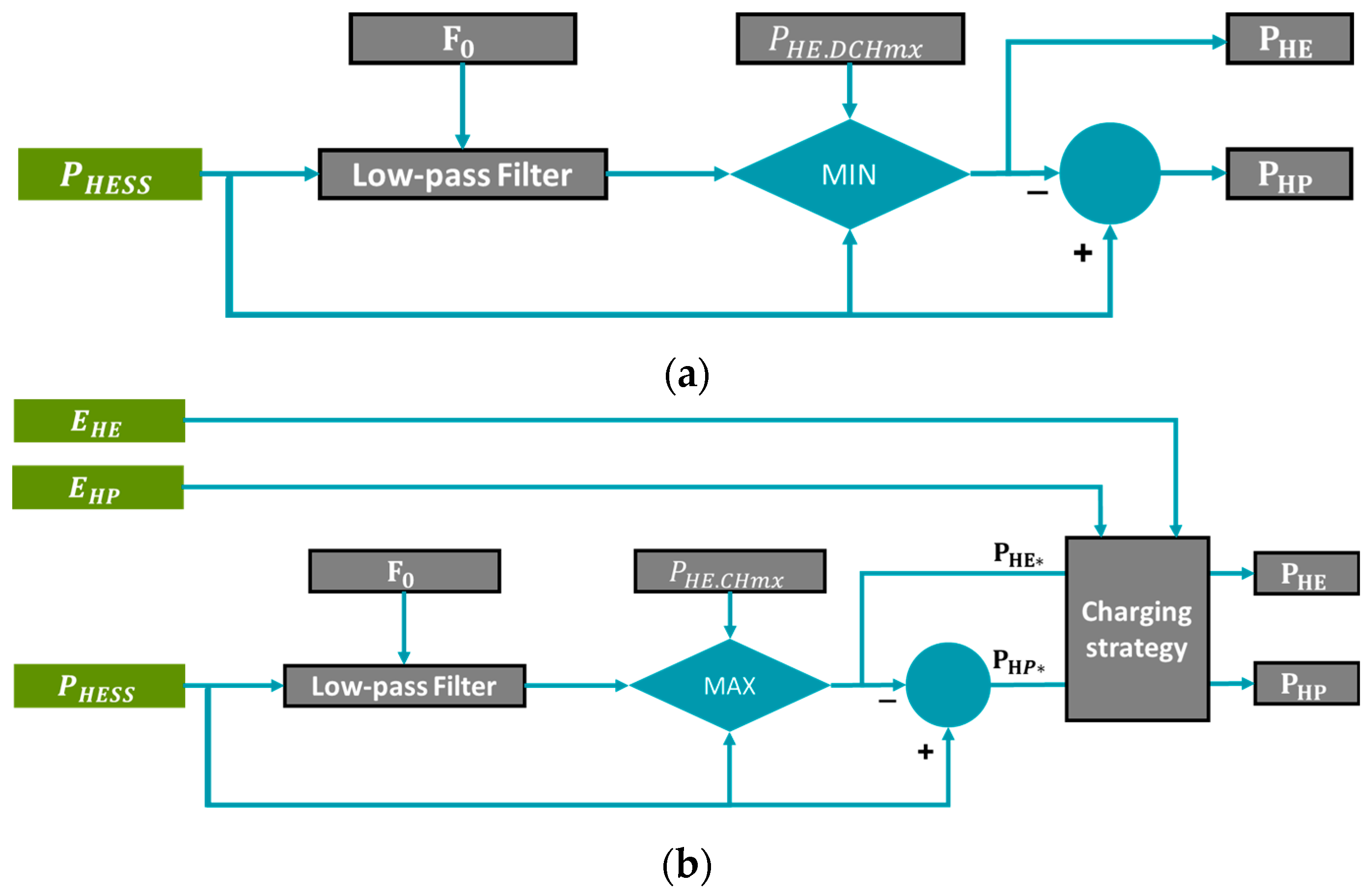
First, the power, energy, and cycling requirements (given implicitly by the load profile) are split into two power output profiles—HE (high energy) and HP (high power)—using the power split algorithm. The power split algorithm is determined by the selected energy management strategy, to illustrate the process at this stage, the power split algorithm based on low pass filtering reported in [
27] is adapted and briefly described here. Alternative algorithms/strategies, as those presented in [
25,
26], can also be adapted in this step; however, a comparison of EMS for HBESS is out of the scope of this study.
Figure 4 illustrates the core power split strategy based on low pass filtering used to determine the share of the load power (P
HESS) that is routed to and from the HE and HP part of the energy storage.
Different combinations of the parameters F
0 and
in
Figure 4 are explored in the optimization, implying that the filter parameters used for one of the time series within the given power profile can be different from the filter parameters used for the other time series of the given power profile. As a result, for each load profile, the power split design space has twice as many free design parameters (i.e., two filter parameters per time series).
The output of the power split algorithm is composed of two design spaces, associated with each battery sub-system. Each design space is defined by four specific requirements, calculated from the power time series split to each battery sub-system:
The minimum usable energy of the battery sub-system;
The required maximum continuous charge power;
The required maximum continuous discharge power;
The annual energy throughput.
Hereafter, we elaborate on the parallel optimal sizing process for each battery sub-system.
2.2.2. Parallel Design of HE and HP Modules
The four specific requirements obtained from the power split algorithm, along with the main battery cell properties (maximum current, energy capacity, and calendar-cycling degradation performance) are the main inputs for the BESS sizing algorithm, which determines the minimum required capacity to be installed so the design lifetime requirement is fulfilled, and the cells can deliver the required power without overpassing its current limits.
Another functionality of the BESS sizing process is to reduce the design space by discarding the designs with higher total HBESS required energy capacity (as those are more costly solutions based on the cell cost) before running the modular BESS design algorithm (which requires more computational time) in the next step.
Then, the modular BESS design algorithm is applied on each battery sub-system (HE and HP) and for all the design alternatives composing the reduced HBESS design space obtained from the BESS sizing algorithm. In general, for a given topology, the modular BESS algorithm explores the associated free design parameters to find the optimal module size (number of battery cells per module and rating of the power converter, if applicable), the number of modules, and the number of strings for a required energy and power capacity of the BESS.
The free design parameters for the modular BESS algorithm are determined by the selected HBESS topology; for example,
Figure 5 shows and summarizes the BESS design algorithm proposed in [
21]. A brief description of this modular BESS design algorithm is presented as follows.
For a given cell type, three free design parameters are enabled on the module level: the number of series (n
sCell) and parallel (n
pCell) connected cells per module and the maximum battery cell utilization ratio
, defined by
where
(unit in Ampere) is the maximum continuous current that the cell can handle and
(unit in Ampere) is the maximum continuous current per cell within the module, so
is always lower or equal to 1, but it allows to design/size all other components of the module according to the string current with more freedom. These three free design parameters can also be considered for the baseline topology, but not for the discrete battery topology (both are sketched in
Section 3.1.1), where only n
pCell and αI
Bmx could be considered as free design parameters (n
sCell = 1).
With the three free design variables defined, the battery array is established, which provides an anchor for the battery cell heatsink and the DC-DC power converter designed. The battery cell heatsink is a water-cooling system based on conductive thermal fins and cold plates, as described in
Section 2.1.3. The DC/DC power module is based on a half-bridge topology, and a full description of the DC/DC converter design algorithm can be found in [
21].
Once the module is specified, the number of modules per string can be calculated. To meet the nominal voltage requirement, there is a minimum number of modules per string to be fulfilled according to the equation below
where
(unit in Volt) is the nominal voltage of the HBESS,
is the cell voltage (unit in Volt) at minimum SOC.
A modular BESS topology has one more degree of freedom, as it is possible to have redundant modules per string (redundant in terms of voltage), so the total number of modules per string (
) is calculated by
with
as the number of redundant modules per string, which is limited by
where
is the ratio of maximum allowed internal system voltage to maximum output voltage;
has been considered for all designs.
is considered as a free design parameter.
The string inductor is designed to limit the string peak-to-peak current ripple for the worst operating conditions, and it is evaluated based on the meta-parameterized approach introduced in [
23], taking as reference technology the DC iron core smoothing reactors series 4ETXX with Cu winding from the manufacturer Siemens. Additionally, the meta-parameterized approach has been modified to account for designs with high current ratings but similar energy contents as the reference technology. Details on performance evaluation are reported in [
21].
Once the optimal sizing is available for the HE and HP battery sub-systems, the mapped HBESS performance space is obtained by the global HBESS performance evaluation, considering the performance indices described in
Section 2.3.
2.3. Design Evaluation Methods
As a third step in the HBESS design process, the design variables generated by the optimization step are evaluated against four KPIs: two energy density indexes (as mechanical integration is out of the scope of this study, the energy density is determined based only on the battery system (i.e., cells, cooling devices, and power converters) itself, which means that the additional weight and space of auxiliary equipment and the required service space around the battery system are not considered in the evaluation), battery system capital cost, and battery system energy losses. They are evaluated based on the methods introduced in the upcoming subsections and briefly explained below:
The gravimetric energy density that is measured in Wh/kg, indicating the energy per installed weight;
The volumetric energy density measured in Wh/L to indicate the energy per installed volume;
The capital costs of the battery system directly influences the affordability of the electric ship;
The total system energy loss, which reveals the energy efficiency, and therefore, the operational cost of the electric ship.
This section explains the methodology of calculation or evaluation of the KPIs.
2.3.1. Evaluation of Losses
The average HBESS losses (
, unit in W) for all topologies are evaluated based on the average system efficiency (
), which is calculated considering the annual energy throughput (
, unit in Wh) and the annual energy losses (
, unit in Wh) associated with a given power profile, as follows:
with
(unit in W) as the power time series of the given profile (
> 0 for discharge;
< 0 for charge, and
(unit in W) are the instantaneous power losses associated with
.
The annual energy throughput is calculated by
where
is the number of operating days of profile power time series
k per year,
is the number of power time series within a given profile, and
is the period of the power time series k (in seconds).
The annual energy loss is calculated by
where
(unit in Wh) are the annual energy losses associated with the operation of the HE battery sub-system, and
(unit in Wh) are the annual energy losses associated with the operation of the HP battery sub-system. The losses of the HE/HP battery sub-systems (
and
, both unit in W) are evaluated considering the losses of the battery cells, the power converter losses, and the string inductor losses as major contributors to the total system power losses.
2.3.2. Evaluation of Total Weight
The overall weight of the battery system for all topologies can be calculated based on
where
and
show the number of HE and HP modules within the HBESS, and
(unit in kg) and
(unit in kg) denote the weight of HE and HP modules, respectively. The module weight for both HE/HP batteries depends on the weight of HE/HP cells (
, unit in kg), heat sink (
, unit in kg), and the power converter (
, unit in kg) (or switching devices).
The weight of the cells is given in the specification sheet in
Section 3.1.3. The number of cells in the modules for each application is calculated based on the optimization tool.
The weight of the cooling system, as illustrated in
Figure 2, can be calculated based on three main components: the thermal conductive fins (to conduct the cell heat to the cold plates), thermal pads (interfacing the battery cells, thermal fins, and cold plates), and the cold plates.
The weight of the power converter is estimated based on the available converters on the market with a voltage and power level close to the investigated applications. In this respect, the weight of the converter is simply assumed to be dependent on the rated power. Therefore, the weight of the central DC/DC converter can be calculated based on the maximum power of the load profile.
2.3.3. Evaluation of Total Volume
The overall volume of the battery system for all topologies can be calculated based on
where
and
show the number of HE and HP modules within the HBESS, and
(unit in litre) and
(unit in litre) denote the volume of HE and HP modules, respectively. The module volume for both HE/HP batteries depends on the volume of HE/HP cells (
, unit in Litre), heat sink (
, unit in Litre), and power converter (
, unit in Litre) (or switching devices).
It must be mentioned that for the baseline topology and the HP battery pack in the discrete HESS topology (both are sketched in
Section 3.1.1), the volume of modules only depends on the volume of the cells and heat sink; as for these two cases, there is no converter on the module level, and the entire battery pack is equipped with a central DC/DC converter.
The summation of the cells’ volume and the heat sink volume for all topologies is estimated according to the thermal management model described in
Section 2.1.3. Since the topologies are using different converter concepts, the volume of power electronic device is topology-dependent and varies from one concept to another one.
2.3.4. Evaluation of Total Cost
As indicated in previous sections, the share of cells, the cooling system, and the power converter are considered in the calculation of the weight and volume of the entire battery, and other components are neglected (for the module-level converter topology, the share of string inductor is also considered).
Since the total cost of the battery is the most important KPI within this study, besides the cost of cells, the cooling system and power converter, the cost of other common components that were indicated in the HBESS schematics in
Section 3.1.1 (such as voltage and temperature sensors, insulation measurement device, HV connections, fuse, coolant ports, etc.) are also considered in the total purchase cost of the system.
The total purchase cost of the HBESS based on the number of HE and HP modules and other common components can be calculated using the following equation
where the cost of each module depends on the cost of cells, heat sink, power converter, and other components in the module that can be written as
The cost of the cells depends on the number of HE and HP cells in each topology. As reported in
Table 1, it is a cost of 150 EUR/kWh and 381 EUR/kWh, for NMC and LTO battery cells, respectively. The cost of a cooling system per module is the outcome of the thermal management model in
Section 2.1.3. The cost of the power converter is estimated considering the voltage and power levels of the module and based on the available converters on the market and/or dedicated converter cost assessment, as in [
21].
It must be mentioned that for the baseline topology and the HP battery pack in the discrete HESS topology (both are sketched in
Section 3.1.1), the cost of modules only depends on the cost of the cells and heat sink; as for these two cases, there is no converter on the module level, and the entire battery pack is equipped with a central DC/DC converter.
The cost of the other common components in Equation (15) and the cost of other module components (
) in Equation (16) depend on the number of components and the unit cost for each one. The number of components varies from one HBESS topology to another, depending on the optimal size for each concept. A list of the unit cost per component is prepared based on the market analysis, which is used for all the topologies. The considered components at the module and string level are summarized in
Section 3.1.1.
3. Input Data and Key Design Requirements
The HBESS development shall be considered a technologically sophisticated process with a multi-disciplinary nature and the need for the different technical fields of expertise (i.e., electrical, thermal, mechanical, control, etc.). Since the purpose of the case study in this work is to demonstrate the generic HBESS design framework, without loss of generality, two key top-level requirements are selected: voltage and lifetime.
3.1. Input Data
3.1.1. Topology Schematic and Specifications
The schematics for the baseline topology, the module level converter topology, and the discrete battery topology are demonstrated in
Figure 6,
Figure 7 and
Figure 8, respectively. To better contrast the three topologies, identical component symbols are used and are summarized in
Figure 9.
The baseline topology, which is based on monotype battery cells, often results in oversized battery packs in order to meet both energy and power requirements at the same time. In the module level, converter topology, each HE/HP module consists of not only HE/HP cells but also power converters, which allows the HE/HP module to be engaged/bypassed separately. Therefore, the whole battery system can be sized and operated according to the actual need of the load profile. In the discrete battery topology, the interconnection pattern between the cells is changeable using switching elements. As a result, the battery characteristics, such as voltage, can be dynamically adapted to the load profile without the need for the power converters, which provides clear advantage in faster and enhanced energy conversion (e.g., bypassing the weakest cell once it has reached the lowest voltage limit). For each application, the battery size will be optimized for the three topologies.
3.1.2. Load Profiles
In theory, all types of vessels can potentially benefit from an HBESS, while this study narrows down the scope to the applications where the potential benefit is considerable. Two criteria have been applied to select application scenarios for this study. First, the energy demand in comparison to the power demand. For instance, a battery system could benefit from HBESS when the energy demand is significantly larger compared to the power or cycling requirements, which results in an oversized high-energy battery system. Second, the shape of the load profile. That is, the load profile should have combinations of full-electric sailing, peak shaving, spinning reserve, load levelling, and boost functions.
Figure 10 shows the load profile for five selected applications, including both primary and secondary cycles (the primary cycles, which represent the operational conditions at the design level of the vessel, are the most common cycles that a vessel performs. Secondary cycles are the operations performed by the battery, which are not based on the average design conditions, and they do not occur during most of the operations. In a nutshell, the secondary cycles have larger energy requirements, while the primary cycles have a higher number of performed cycles). It must be noted that for the urban ferry, the load profiles are given for 2 full days, while for the other applications, the load profiles are given for 1 full day. The required energy for each cycle can be calculated based on the load profile. As mentioned earlier, a fixed voltage of 1000 V is assumed for all the applications.
3.1.3. Battery Cell Specifications
The specifications and the technical parameters that serve as input to the optimization algorithm are shown in
Table 1. The lithium nickel manganese cobalt oxide (NMC) and lithium titanate oxide (LTO) battery types, which are standard cell technologies in electric ships, are considered high-energy and high-power battery cells in this work [
11].
Table 1.
Specifications of the battery cells used for optimization.
Table 1.
Specifications of the battery cells used for optimization.
| Battery Specifications | NMC | LTO |
|---|
| Capacity [Ah] | 94 | 23 |
| Nominal voltage [V] | 3.68 | 2.3 |
| Operating voltage [V] | 2.7–4.15 | 1.5–2.7 |
| Shape [-] | Prismatic | Prismatic |
| Dimension (W × H × T) [mm] | 173 × 125 × 45 | 115 × 103 × 22 |
| Volume [L] | 0.97 | 0.26 |
| Weight [kg] | 2.1 | 0.55 |
| Gravimetric energy density [Wh/kg] | 165 | 96 |
| Volumetric energy density [Wh/L] | 356 | 204 |
| Gravimetric power density [W/kg] | 1450 | 1800 |
| Volumetric power density [W/L] | 3144 | 3846 |
| Continuous discharge current [A] | 150 | 92 |
| Peak discharge current [A] | 409 | 184 |
| Continuous charge current [A] | 70 | 92 |
| Peak charge current [A] | 270 | 184 |
| Cycle life | >11,000 | >4000 |
| State of health (SOH) corresponding to the end of life (EOL) (%) | 80 | 80 |
| Thermal conductivity [°C/W] | 30 (In-plane)
1.7 (Trough-plane) | 31 (In-plane)
0.8 (Trough-plane) |
| Expected increment ratio of cell resistance EOL (SOH = 80%) [-] | 1.276 | 1.94 |
| Cost [EUR/kWh] | 150 | 381 |
3.2. Key Requirements
3.2.1. Voltage
The electrical integration and the required operating voltage of the vessels is one of the main requirements for the marine battery systems addressed in different applications. It has a considerable impact on the optimization of the topologies within the present task. In general, the connection of the batteries onboard vessels can be realized through a fixed voltage or floating voltage DC bus. Normally, in marine application, the nominal DC bus voltage can vary from 700 V to 1000 V [
11]. In this respect, a fixed voltage of 1000 V is selected as a general requirement for all the vessels’ load profiles that are investigated in this study.
3.2.2. Lifetime
The design life of the battery is an important factor that greatly affects the size and cost of the battery. The design life of a battery system depends on multiple variables, such as temperature, number of cycles, depth of discharge, and C-rates. The expected design life of a battery system is usually based on an estimation of the operational profile and the number of cycles the batteries will make.
In practice, the actual cycles that the battery will be making and the temperatures inside the battery room will vary from this estimation. However, the lifetime calculation is needed to determine the commercial viability of a battery-powered vessel or to choose the type and size of battery system that will be installed. Although most vessels have an expected lifetime between 25 to 40 years, this is currently not achievable for battery system technologies. Therefore, a design life must be determined for the batteries, after which it is acceptable from a commercial or operational point of view to replace the battery system with a new one. Currently, this design life is usually determined at approximately 10 years in the maritime industry from the commercial and operational point of view [
11]. Hence, all the HBESS topologies within this study are designed for a lifetime of 10 years for all the given load profiles.
3.3. Key Assumptions
This section summarizes the key assumptions adopted in this study such that the reproducibility of this study is enhanced:
Rule-based energy management strategy is adopted as charging infrastructure is unavailable in the sea;
Mechanical integration has not been considered in the optimal sizing;
The design and cost of onboard charging facilities are not taken into consideration for the design;
The end-of-life recycling cost of the battery system is not considered in this study.
4. Case Studies and Comparison of HBESS Topologies
To demonstrate the HBESS design guidelines as proposed in this study, three topologies have been optimized with reference to the same load profile and the same battery cells.
4.1. The Battery Sizing Results of Different HBESS Topologies
Table 2 gives an overview of how the different topologies are designed. It must be noted that based on the optimization results for each topology, for some applications, a mono-type battery (either NMC or LTO) system leads to the minimum cost, while for other applications, a hybrid battery system is the optimal solution.
4.2. The KPIs of the Different HESS Topologies
The following subsections provide an overview of the normalized KPI outcome, i.e., the score of the baseline is considered 100% as a reference point.
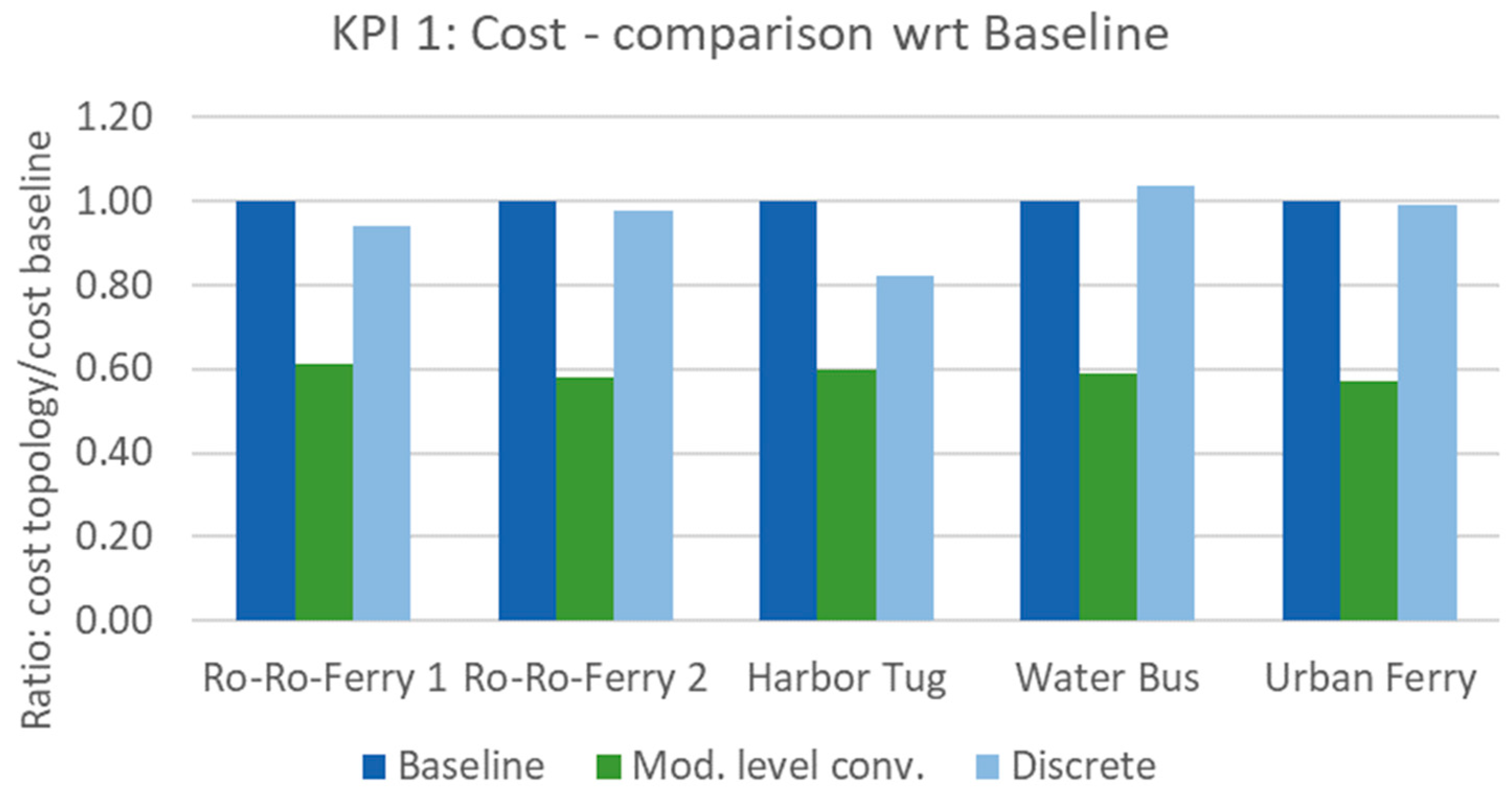
4.2.1. Total Battery System Cost
The costs of different topologies in different load scenarios are depicted in
Figure 11. In general, it can be observed that the module level converter topology realized the lowest overall cost in all load scenarios. There are two reasons behind the fact that the module level converter topology has the lowest cost. First, the exploitation of battery hybridization has the lowest total energy (kWh) need. Second, the module level converter topology does not significantly increase the amount of switching devices in comparison to the baseline topology. On the other hand, a discrete battery topology significantly increases the need for power switch devices, which allows the battery cell to enable the engagement or bypassing of the cells.
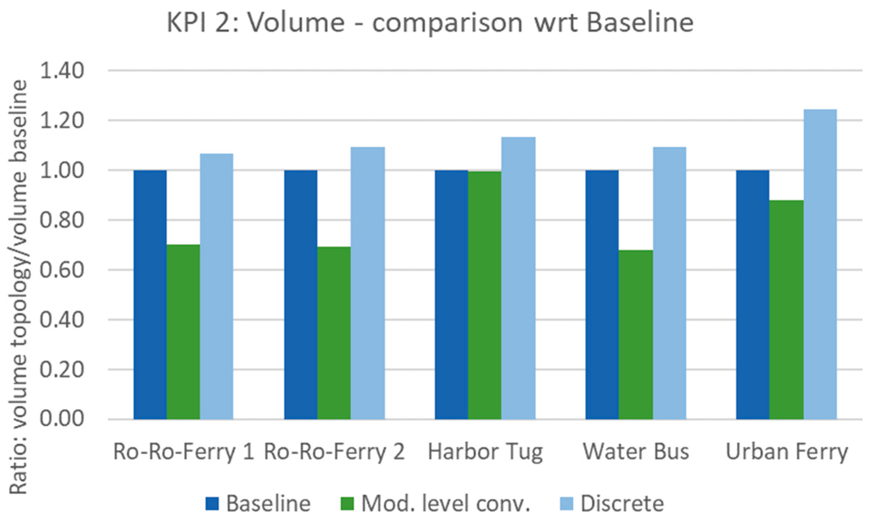
4.2.2. Total Battery System Volume
Figure 12 shows the results of the total battery system volume, which indicates that the module level converter topology realized the most compatible architecture. Similar to the total battery system cost, this is mainly due to the minimum number of cells and switching devices needed. The discrete battery topology underperforms compared to the baseline topology, mainly due to its high demand for power switching devices. By comparing the battery system sizing results in
Table 2, one can also find that the level of hybridization is negatively correlated to the performance of volume, which implies that battery system hybridization can contribute to the creation of a more compact design when the volume density is a critical requirement.
4.2.3. Total Battery System Weight
The total battery system weight of the different topologies is evaluated in
Figure 13. Intuitively, the weight of the battery system is largely driven by two major factors. First, the weight of battery cells, which explains the highest total gravimetric energy density of the module level converter topology. Second, the weight of power switching devices, which explains the lowest total gravimetric energy density of discrete battery topology.
4.2.4. Total Battery System Losses
Figure 14 shows the overview of the losses of the different topologies; lower height of the bars represents lower total system losses. It is evident that the modular HBESS design increases energy efficiency significantly. Moreover, the module level converter topology renders half of the total energy losses compared to the discrete battery topology, which implies that power switching devices account for approximately half of the energy losses.
5. Discussion
Overall, it can be concluded that in the load scenarios included in this study, the concept of battery system hybridization has shown a clear advantage in terms of energy efficiency (i.e., energy losses) and energy density. Among the three topologies and given the selected KPIs in this study, the module level converter topology outperforms other topologies in this study with reference to all load scenarios. This is mainly due to its exploitation of hybridization, which reduced the need of the total amount of battery cells, while at the same time, it does not lead to a significant increase in the number of switching devices. The dominant role of switching devices becomes prominent in load scenarios where the required number of cells is low. In these scenarios, the battery system design based on discrete battery topology has the worst performance because the flexibility of this topology is greedy to switching (i.e., power conversion) devices.
By cross comparing different topologies, we find that the energy density performance is highly dependent on the HBESS topology; integrating too many power switching devices can worsen the energy density performance. By cross comparing different load profiles, one can find that the energy density performance is positively correlated to the level of hybridization.
Nevertheless, this study has its limitations, which might influence the findings in this study. First, the optimization algorithm is sufficiently generic because the modular BESS design algorithm (detailed in
Section 2.2) requires input data that are topology-dependent. Second, the KPIs included in this study do not reflect the manufacturability and maintainability of the battery system. In this regard, the discrete battery topology, which enables the highest flexibility, has clear advantage if the manufacturability and maintainability is taken into consideration. Third, the load scenarios are assumed to be deterministic, while there exist uncertainties (e.g., weather conditions) in reality.
6. Conclusions
In the context of maritime transportation sector electrification, battery hybridization has been identified as a promising way of meeting the critical requirements on energy and power density, as well as lifetime and safety. Today, multiple promising battery hybridization topologies have been identified using prior experience in the electrification of the road transportation sector. However, there is a lack of a generic framework underpinning the optimal design of a hybrid energy storage system for maritime applications to compare different topologies against the key design requirements and considerations of maritime HBESS. This study proposed a generic framework for the design and evaluation of modular battery hybrid energy storage systems for full-electric marine applications. In doing so, generic key component models are created, and serve as input to an optimization algorithm that optimizes the hybrid battery system sizing towards the key requirements of the ship design, followed by evaluation methods that derive KPIs of the HBESS design that enables a quantitative comparison between different HBESS topologies.
The results shows that the generic HBESS design and evaluation framework presented in this study has successfully set a level playground for HBESS topologies, which allows the battery system designer to evaluate and compare different HBESS topologies with reference to key design considerations such as energy density, cell types, and total energy losses. It is also worth noting that, as has been demonstrated in the case study, the generic HBESS design framework is also capable of handling a monotype cell battery system, which shall be considered a special case of HBESS.
Naturally, the design of a battery system is a complex iterative process; the framework and the models shall be regarded as tools that facilitate the battery system sizing with reference to the major design considerations (such as battery cell types and energy management strategy) in the battery system conceptualization phase, instead of a design supporting tool (serves the purpose of detailed systems design) that covers and evaluates the complete set of design parameters.
In addition, the case study comparing one baseline monotype design and two HBESS topologies has shown a clear advantage of battery hybridization in most of the use-cases, as battery hybridization can adjust the proportion of high-energy and high-power battery cells towards the specific load profile (i.e., application scenario). As a result, the total costs of the battery systems are decreased with better energy density and energy efficiency performance. Among the three topologies considered in this study, the module level converter topology has shown a clear advantage in almost all selected KPIs due to its battery hybridization and reduced need for power converter devices. It has also been found that the total required number of power converter devices is positively correlated to the flexibility level of the topology. As a result, in application scenarios where the required battery capacity is low, battery hybridization using a flexible topology (i.e., the discrete battery topology) results in worse KPIs in comparison to the benchmark monotype battery system.
Based on the framework presented and the lessons learned in this study, future studies can be carried out in two directions. First, the topology design can be integrated into the global architectural design optimization of the ship to further reduce the total cost of ownership of the whole ship. Second, from a sustainability point of view, the second life usage of the battery (as a module) can be considered in the optimization algorithm to lower the refurbishing cost of the battery system.
Author Contributions
Conceptualization, Z.T. and J.S.; methodology, Z.T. and R.B.-C.; software, R.B.-C. and M.A.; validation, R.B.-C., M.A. and Z.T.; formal analysis, Z.T.; writing—original draft preparation, Z.T. and R.B.-C.; writing—review and editing, R.B.-C., M.A., O.M. and J.D.S.; visualization, Z.T.; supervision, J.S.; project administration, Z.T., O.M., J.D.S. and J.S. All authors have read and agreed to the published version of the manuscript.
Funding
This research has received funding from the European Union’s Horizon 2020 research and innovation programme under grant agreement no. 963560.
Data Availability Statement
Not applicable.
Acknowledgments
This research was developed under the framework of SEABAT project—“Solutions for largE bAtteries for waterBorne trAnsporT”.
Conflicts of Interest
The authors declare no conflict of interest.
References
- International Maritime Organization. Review of Maritime Transport 2015; International Maritime Organization, United Nations: Geneva, Switzerland, 2015. [Google Scholar]
- International Maritime Organization. Third IMO Greenhouse Gas Study 2014; International Maritime Organization: London, UK, 2015. [Google Scholar]
- Yuan, Y.; Wang, J.; Yan, X.; Shen, B.; Long, T. A review of multi-energy hybrid power system for ships. Renew. Sustain. Energy Rev. 2013, 132, 110081. [Google Scholar] [CrossRef]
- Miola, A.; Ciuffo, B.; Giovin, E.; Marra, M. Regulating Air Emissions from Ships—The State of the Art on Methodologies, Technologies and Policy Options; Publications Office of the European Union: Luxembourg, 2010. [Google Scholar]
- International Maritime Organization. International Convention for the Prevention of Pollution from Ships (MARPOL); International Maritime Organization: London, UK, 1983. [Google Scholar]
- Internaltional Maritime Organization. Resolution MEPC.203(62); Marine Environmental Protection Committee (MEPC): London, UK, 2011. [Google Scholar]
- ABS. Ship energy efficiency measures advisory. In Ship Energy Efficiency Measures—Status and Guidance; ABS: Houston, TX, USA, 2013. [Google Scholar]
- Balsamo, F.; Capasso, C.; Lauria, D.; Veneri, O. Optimal design and energy management of hybrid storage systems for marine propulsion applications. Appl. Energy 2020, 278, 115629. [Google Scholar] [CrossRef]
- Damian, S.E.; Wong, L.A.; Shareef, H.; Ramachandaramurthy, V.K.; Chan, C.; Moh, T.; Tiong, M.C. Review on the challenges of hybrid propulsion system in marine. J. Energy Storage 2022, 56, 105983. [Google Scholar] [CrossRef]
- Inal, B.; Charpentier, J.-F.; Deniz, C. Hybrid power and propulsion systems for ships: Current status and. Renew. Sustain. Energy Rev. 2022, 156, 111965. [Google Scholar] [CrossRef]
- Akbarzadeh, M.; De Smet, J.; Stuyts, J. Battery Hybrid Energy Storage Systems for Full-Electric Marine Applications. Processes 2022, 10, 2418. [Google Scholar] [CrossRef]
- Zimmermann, T.; Keil, P.; Hofmann, M.; Horsche, M.F.; Pichlmaier, S.; Jossen, A. Review of system topologies for hybrid electrical energy storage systems. J. Energy Storage 2016, 8, 78–90. [Google Scholar] [CrossRef]
- Schubert, C.; Hassen, W.F.; Poisl, B.; Seitz, S.; Schubert, J.; Usabiaga, E.O.; Gaudo, P.M.; Pettinger, K.-H. Hybrid Energy Storage Systems Based on Redox-Flow Batteries: Recent Developments, Challenges, and Future Perspectives. Batteries 2023, 9, 211. [Google Scholar] [CrossRef]
- Tostado-Véliz, M.; Ghadimi, A.A.; Miveh, M.R.; Sánchez-Lozano, D.; Escamez, A.; Jurado, F. A Novel Stochastic Mixed-Integer-Linear-Logical Programming Model for Optimal Coordination of Hybrid Storage Systems in Isolated Microgrids Considering Demand Response. Batteries 2022, 8, 198. [Google Scholar] [CrossRef]
- Forestieri, J.N.; Farasat, M. Energy flow control and sizing of a hybrid battery/supercapacitor storage in MVDC shipboard power systems. IET Electr. Syst. Transp. 2020, 10, 275–284. [Google Scholar] [CrossRef]
- Kim, K.; An, J.; Park, K.; Roh, G.; Chun, K. Analysis of a Supercapacitor/Battery Hybrid Power System for a Bulk Carrier. Appl. Sci. 2019, 9, 1547. [Google Scholar] [CrossRef]
- Diab-Marzouk, A. Lightweight DC-DC Converter with Partial Power Processing and MPPT for a Solar Powered Aircraft; University of Toronto: Toronto, ON, Canada, 2015. [Google Scholar]
- Liu, S.; Forsyth, A.; Todd, R. Battery Loss Modelling Using Equivalent Circuits. In Proceedings of the IEEE Energy Conversion Congress and Exposition (ECCE), Baltimore, MD, USA, 29 September–3 October 2019. [Google Scholar]
- Kolar, J.W.; Biela, J.; Waffler, S.; Friedli, T.; Badstuebner, U. Performance trends and limitations of power electronic systems. In Proceedings of the IEEE 6th International Conference on Integrated Power Electronics Systems (CIPS), Nuremberg, Germany, 16–18 March 2010. [Google Scholar]
- Zekalabs. RedPrime DC-DC Converter 200 kW, 1200 V. Zekalabs: Sofia, Bulgaria. Available online: https://www.zekalabs.com/products/non-isolated-high-power-converters/dc-dc-converter-200kw-1200v (accessed on 10 February 2023).
- Barrera-Cardenas, R.A. AN 22.12.37—Modular MultiLevel Energy Storage System: Modelling and Design Optimization (Version 1.2); Sintef Energi AS: Trondheim, Norway, 2023; Available online: https://hdl.handle.net/11250/3063141 (accessed on 25 April 2023).
- Graovac, D.; Purschel, M.; Kiep, A. MOSFET Power Losses Calculation Using the Datasheet Parameters, V1.1 ed.; Infineon Technologies AG: Neubiberg, Germany, 2006. [Google Scholar]
- Barrera-Cardenas, R.; Molinas, M. Meta-Parametrised Meta-Modelling Approach for Optimal Design of Power Electronics Conversion Systems. Ph.D. Thesis, Norwegian University of Science and Technology, Trondheim, Norway, 2015. [Google Scholar]
- Huang, A. Application Note AN 2012-03: Infineon OptiMOS Power MOSFET Datasheet Explanation; Infineon Technologies Austria AG: Villach, Austria, 2012. [Google Scholar]
- Sankarkumar, R.S.; Natarajan, R. Energy management techniques and topologies suitable for hybrid energy storage system powered electric vehicles: An overview. Int. Trans. Electr. Energy Syst. 2021, 31, e12819. [Google Scholar] [CrossRef]
- FuiTie, S.; WeiTan, C. A review of energy sources and energy management system in electric vehicles. Renew. Sustain. Energy Rev. 2013, 20, 82–102. [Google Scholar]
- Barrera-Cardenas, R.A. AN 22.12.38—Hybrid Energy Storage System Based on Modular Multilevel Topology: Design and Optimization; Sintef Energy Research: Trondheim, Norway, 2022. [Google Scholar]
Figure 1.
HBESS design and evaluation framework. The exogeneous input is represented by green blocks, the key HBESS mathematical models are represented by grey blocks, the evaluation methods are represented by a red-colored block, while the output information is colored in blue.
Figure 1.
HBESS design and evaluation framework. The exogeneous input is represented by green blocks, the key HBESS mathematical models are represented by grey blocks, the evaluation methods are represented by a red-colored block, while the output information is colored in blue.
Figure 2.
Battery module with cooling system based on thermal conductive fins and cold plates.
Figure 2.
Battery module with cooling system based on thermal conductive fins and cold plates.
Figure 3.
HBESS design algorithm based on Modular BESS topology. The exogeneous input is represented by green blocks, the key HBESS design variables/processes are represented by grey blocks, while the output information is colored in blue.
Figure 3.
HBESS design algorithm based on Modular BESS topology. The exogeneous input is represented by green blocks, the key HBESS design variables/processes are represented by grey blocks, while the output information is colored in blue.
Figure 4.
Power split strategy during operation (
a) and charging (
b) based on low pass filtering [
27]. The exogeneous input is represented by green blocks, the key HBESS design variables/processes are represented by grey blocks, while the output information is colored in blue.
Figure 4.
Power split strategy during operation (
a) and charging (
b) based on low pass filtering [
27]. The exogeneous input is represented by green blocks, the key HBESS design variables/processes are represented by grey blocks, while the output information is colored in blue.
Figure 5.
Modular-multilevel battery energy storage design algorithm [
21].
Figure 5.
Modular-multilevel battery energy storage design algorithm [
21].
Figure 6.
Detailed schematic representation of the baseline topology. The battery pack comprises Y parallel strings, in which X battery modules are connected in series. The battery cells are clustered in the modules within a series connection, and each module is equipped with a battery management system (BMS). The BMS monitors the voltage of the cells and protect them from over- and under-voltage. Furthermore, it monitors the temperature of the cells and balances the cells within the modules based on the measured voltage, temperature, and current. A bidirectional DC/DC converter is used to control the power and regulate the voltage according to the requirements on the DC bus. The DC/DC converter is used here since a fixed DC-bus voltage is assumed for all the applications.
Figure 7.
Detailed schematic representation of the module level converter topology. The overlying idea of this topology is to modularize the DC/DC power converter such that each battery module contains both several battery cells and a DC/DC converter forming an energy storage system module (ESS module). These ESS modules are then connected in series and parallel as needed to obtain the desired DC voltage, power rating, and energy storage capacity.
Figure 8.
Detailed schematic representation of discrete battery topology. A discrete or reconfigurable battery is a system in which the interconnection pattern between the cells is changeable using switching elements. The switching elements allow the engagement or bypassing of the cells, and accordingly, the battery characteristics, such as voltage, can be dynamically adapted to the load profile without the need for power converters.
Figure 9.
Symbols of components in the detailed schematic representation of different topologies.
Figure 9.
Symbols of components in the detailed schematic representation of different topologies.
Figure 10.
Load profile of the applications: (a) Ro-Ro ferry 1; (b) Ro-Ro ferry 2; (c) Harbor tug; (d) Waterbus; (e) Urban ferry.
Figure 10.
Load profile of the applications: (a) Ro-Ro ferry 1; (b) Ro-Ro ferry 2; (c) Harbor tug; (d) Waterbus; (e) Urban ferry.
Figure 11.
Results of KPI 1—cost: the three topologies are compared to the baseline for the different applications.
Figure 11.
Results of KPI 1—cost: the three topologies are compared to the baseline for the different applications.
Figure 12.
Results of KPI 2—volume: the three topologies are compared to the baseline for the different applications.
Figure 12.
Results of KPI 2—volume: the three topologies are compared to the baseline for the different applications.
Figure 13.
Results of KPI 3—Weight: the three topologies are compared to the baseline for the different applications.
Figure 13.
Results of KPI 3—Weight: the three topologies are compared to the baseline for the different applications.
Figure 14.
Results of KPI 4—battery system losses: the three topologies are compared to the baseline for the different applications.
Figure 14.
Results of KPI 4—battery system losses: the three topologies are compared to the baseline for the different applications.
Table 2.
Overview of the outcome of the optimisations for different topologies in function of the applications (kWh).
Table 2.
Overview of the outcome of the optimisations for different topologies in function of the applications (kWh).
| Load Profile | Ro-Ro Ferry 1 | Ro-Ro Ferry 2 | Harbor Tug | Water Bus | Urban Ferry |
|---|
| Battery cell type | NMC | LTO | NMC | LTO | NMC | LTO | NMC | LTO | NMC | LTO |
| Baseline (monotype) | 3947 | 0 | 0 | 2387 | 2502 | 0 | 0 | 2226 | 0 | 204 |
| Module level converter | 944 | 1085 | 217 | 2318 | 2534 | 0 | 124 | 2175 | 0 | 216 |
| Discrete battery | 1412 | 947 | 0 | 2387 | 2567 | 0 | 0 | 2231 | 0 | 245 |
| Disclaimer/Publisher’s Note: The statements, opinions and data contained in all publications are solely those of the individual author(s) and contributor(s) and not of MDPI and/or the editor(s). MDPI and/or the editor(s) disclaim responsibility for any injury to people or property resulting from any ideas, methods, instructions or products referred to in the content. |
© 2023 by the authors. Licensee MDPI, Basel, Switzerland. This article is an open access article distributed under the terms and conditions of the Creative Commons Attribution (CC BY) license (https://creativecommons.org/licenses/by/4.0/).

 ,
, 


