Article

General Decoupling and Sampling Technique for Reduced-Sensor Battery Management Systems in Modular Reconfigurable Batteries

1
Department of Electrical and Computer Engineering, Technical University of Kaiserslautern, 67663 Kaiserslautern, Germany
2
Department of Electrical and Computer Engineering, Duke University, Durham, NC 27708, USA
3
China Euro Vehicle Technology, A Geely Company, 41755 Gothenbur, Sweden
*
Author to whom correspondence should be addressed.
Batteries 2023, 9(2), 99; https://doi.org/10.3390/batteries9020099
Submission received: 27 December 2022 / Revised: 10 January 2023 / Accepted: 16 January 2023 / Published: 1 February 2023
(This article belongs to the Special Issue Future Smart Battery Management Systems)

Abstract

:
The capacity and voltage rating of battery packs for electric vehicles or stationary energy storages are increasing, which challenge battery management and monitoring. Breaking the larger pack into smaller modules and using power electronics to achieve dynamic reconfiguration can be a solution. Reconfigurable batteries come with their own set of problems, including many sensors and complex monitoring systems, high-bandwidth communication interfaces, and additional costs. Online parameter estimation methods can simplify or omit many of these problems and reduce the cost and footprint of the system. However, most methods require many sensors or can only estimate a subset of the elements in the module’s equivalent circuit model (ECM). This paper proposes a simple decoupling technique to derive individual modules’ voltage and current profiles from the output measurements without direct measurement at the modules. The determined profiles can achieve a high sampling rate with minimum communication between the battery management system (BMS) and the modules. With accurate profiles, an estimation technique can easily determine the parameters of the modules. Provided simulations and experiments confirm this claim by estimating the parameters of a first-order ECM with a parallel capacitor. The proposed technique reduces the number of sensors from 2N + 2 to only two at the pack’s output terminals.

1. Introduction

Battery electric vehicles are the preferred choice in comparison to combustion-engine vehicles to reduce greenhouse gas emissions of passenger cars and the transportation sector [1,2]. Concurrently, with the increased penetration of renewable energy sources and application of power electronics, interest in stationary storages for the purpose of grid stabilization is growing [3,4,5]. Moreover, most applications, particularly within the electromobility and stationary energy storages, observe an exponential growth in energy capacity and voltage rating of the battery system [6,7,8]. The high-energy and high-power battery packs in these applications typically consist of a large number (up to several thousand) of individual battery cells which are connected in series and parallel arrangements by soldering or welding joints [9,10,11]. However, large battery packs are less fault-tolerant and prone to parameter variations [12,13,14]. Furthermore, these require a more complex monitoring system which can make a cost-efficient design of the battery management system and balancing circuitry challenging [15,16,17]. In addition, the battery pack’s lifetime and usable capacity are constrained by the weakest battery cell [18,19]; when one cell in the string is empty, the whole battery pack has to be considered empty; if one cell is hot, the power has to be limited for the whole string; and if a cell is dead, the string becomes unusable.
Alternatively, bulky battery packs can be divided into a collection of smaller modules where fully-controllable power electronics replace the fixed connections to offer dynamic reconfiguration capabilities [20,21,22]. Due to the modular and fully controllable architecture, such batteries are often referred to as (modular) reconfigurable or smart batteries [23,24,25,26]. The integration of the power electronics allows for rearranging the connection of each module within the battery cell string/array to balance the individual state of charges (SOC) or temperatures of the modules [27,28,29], perform fault prevention or mitigation [30,31], increase the system efficiency [32,33], and regulate the load flow of the individual modules to improve the reliability or lifetime of the system [34]. Therefore, reconfigurable batteries inherently combine many conventional functions of generic battery management and energy conversion systems [35,36]. Furthermore, dynamically reconfiguring the battery modules can create a multilevel-output waveform which improves the output current quality (total harmonic distortion) [37,38,39] which, in turn, increases the current control bandwidth [40], while reducing the common mode voltage [41,42]. In [41,43,44], a wide selection of modular battery topologies is described for both AC and DC applications. A higher modularity in the design of the pack can also be helpful with respect to the module arrangement and design of the physical shape of the pack. For example, it can allow more freedom to optimize the weight distribution for electromobility application. The added cost of wiring and complexity can also be improved with better integration of the electronics with the modular design of the system, to keep the complexity to a minimum.
Although modular reconfigurable batteries offer clear advantages in comparison with hard-wired packs, they still suffer some drawbacks, such as increased ohmic battery losses and intricate control requirements [45,46]. With many degrees of freedom and the need for monitoring many modules, a modular battery architecture can substantially increase the complexity and system costs due to the many sensors, gate drivers, and related electronics [47,48,49]. A monitoring system based on a conventional battery management systemm (BMS) requires voltage and current sensors for each module and a dedicated communication interface between the central controller and the modules [50,51]. Aside from costly measurement and isolation circuits, the high number of signals can overload the communication bus or decrease the update rate, diminishing the appeal of such methods [52,53,54].
As a simple solution, this work demonstrates that simple measurements at the output of a reconfigurable battery system combined with the knowledge of the modules’ connections within the string contain the necessary information to determine each module’s voltage and current profile without directly measuring them. The derived voltage and current profiles can help to estimate the parameters of each individual battery module [47,52]. In other words, since the arrangement of the modules within a battery string is constantly changing but known, this paper presents a decoupling method to derive the voltage and current profile of the individual modules from the voltage and current sensors at the output terminals of the battery system (requiring only two system-level-sensors). These two sensors already exist for controlling the output and the string current; hence, the method is even compatible in existing designs.
This idea is inspired by the capacitor voltage estimation in modular multilevel converters (MMCs) [55]. For example, as demonstrated in [56], a simple sliding-mode observer to track the module voltages in the discrete-time domain minimizes the communication requirements. Similar other approaches exist in the literature [57,58,59,60,61] which focus on the capacitor voltage estimation in MMCs, with different levels of accuracy and complexity. Although these approaches are advantageous in reducing the system cost and complexity, they are only applicable for tracking the average terminal voltage of capacitor-based modules and mostly disregard other types of energy storages with more complex equivalent circuit models (ECM) [61,62,63,64]. Therefore, these methods do not scale well for batteries since these have a nonlinear voltage–current behavior, which can only be represented by intricate ECMs [47,52,65].
From the BMS perspective, the ECM parameters are crucial as most monitoring functionalities, including charge or health monitoring and power capability estimation, depend heavily on an accurate battery model [41,66,67,68,69]. Studies have shown that these parameters vary heavily with the operating condition, SOC, and state of health (SOH), making developing accurate models even more challenging [70,71]. In a conventional BMS, an accurate battery model for specific SOC and currents is developed as a look-up table which is gradually updated as the battery ages [72,73]. However, methods that accurately update these parameters require constant monitoring of the voltage and current of the battery [74,75]. In recent years, there have been some attempts to improve the accuracy of the battery models for modular reconfigurable batteries that consider the peculiar behavior of batteries in response to a pulsating current [76,77]. Concurrently, attempts to improve some of the reduced sensor estimation methods considering the ECM of the batteries are made [47,52,78]. One of the simplest approaches is modeling the battery behavior with a variable voltage source in series with an equivalent circuit resistor. With the help of current variations, the equivalent series resistance of the module and the open-circuit voltages (OCVs) can be determined by tracking the voltage drop for different operating points [78,79]. While the method can appeal to some applications, the zero-order ECM needs to offer more information [80,81]. However, determining the parameters of higher-order ECMs for the batteries requires having the module’s accurate voltage and current profile during the current variations, which goes beyond the capabilities of existing methods.
This paper proposes a decoupling technique that accurately determines every module’s voltage and current profile without any direct measurement at the module level. The decoupling technique can achieve synchronized sampling frequencies as high as the module’s switching rate, which is sufficiently large to estimate all the required parameters of the battery. The fixed and synchronized sampling rate simplifies the parameter estimation. Moreover, this paper develops a simplified second-order ECM for batteries with an optional parallel capacitor. The proposed model, combined with an estimator, demonstrates the applicability and accuracy of the developed decoupling technique. Compared to conventional BMSs, as shown in [78,82], the proposed technique can reduce the number of sensors from 2 N + 2 (sensors for module current and module voltage) in a battery string with N modules to only two at the output terminals (output voltage and current of the pack). Additionally, the decoupling technique contains only simple scalar mathematics, does not require any computationally demanding calculations, and can be easily integrated into the switching function of the modules. As it is possible to track the exact voltage and current profile during the current variations, it is possible to estimate the ECM parameters of individual modules which capture the dynamics of the battery system more accurately [53,62,83]. Proposing a new estimation technique is not the main innovation of this paper. Consequently, a state-of-the-art estimator provides proof of concept and shows how the developed decoupling technique can be integrated with an estimation method. Similarly, other estimation methods with different levels of computation and complexity can also be combined with the proposed decoupling technique [84,85,86,87,88,89]. In addition to reducing the number of sensors and the size of the overall monitoring system, the necessary data communication can be significantly reduced. The effectiveness of the proposed technique is verified through simulations and experiments.
The remainder of this paper is organized as follows: Section 2 introduces the modular-reconfigurable battery system and its working principles. Section 3 proposes an algorithm for estimating the electrical equivalent circuit parameters of the battery module. Section 4 discusses the simulations and the obtained experimental results. Finally, the last section concludes the paper with final remarks.

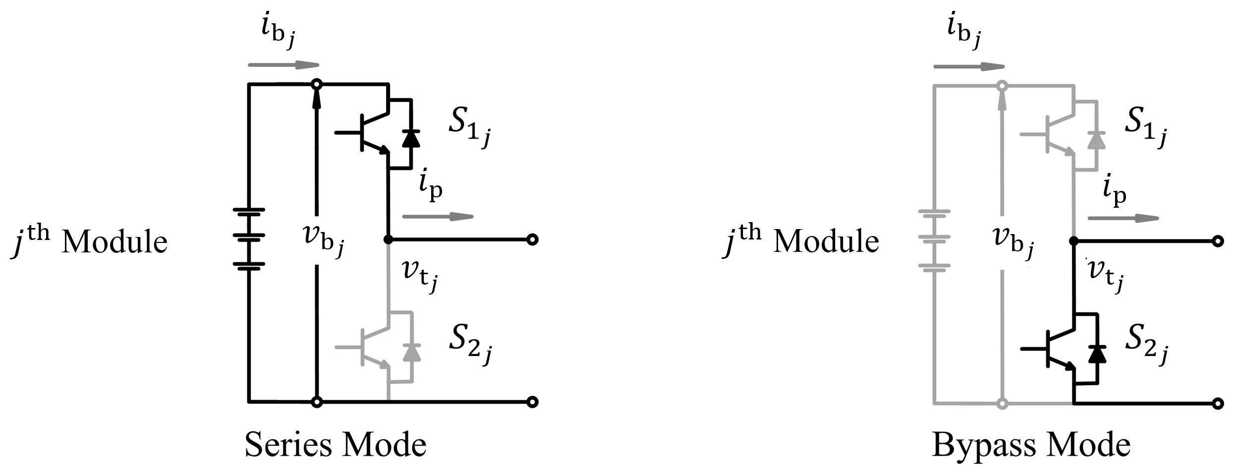
2. System Description

Figure 1 depicts the modular reconfigurable battery where v b j and i b j are the battery voltage and current of the j th module, respectively [90]. The output voltage of the j th module is denoted by v t j . They form the vectors v b , i b , and v t where j { 1 , 2 , , N } . The modules have been connected in series and supply the load through a low-pass filter formed by L and C. v p and i p as the terminal voltage and current of the whole reconfigurable battery are independently measured for controlling the output voltage and current of the system. The battery management system or the central controller can also use these signals for monitoring purposes.
Two switches and their anti-parallel diodes (in half-bridge topology) in parallel with the battery form one module which can offer bypass and series connections, as illustrated in Figure 2 for the j th module [47]. The upper switch in the j th modules is S 1 j , and the lower switch is S 2 j . The vector S denotes the state of all the modules. The j th element of S equals one if the j th module operates in the series mode and zero if it is bypassed. Therefore, considering switches and diode resistances, the general equation of the string voltage follows
v p = S T × v b N . r on . i p R . i p
where “×”, “.”, and “T” denote the matrix product, the normal product, and the transposition operator, respectively. r on is the on-state resistance of the switches or diodes in each module, R is the parasitic series resistance of the inductor L, S = [ S 1 S 2 S N ] T , and v b = [ v b 1 v b 2 v b N ] T .
Considering a single battery with an optional parallel capacitor ( C p j ) to reduce the ripple as Figure 3a illustrates, the equivalent circuit based on the first-order ECM for the battery is shown in Figure 3b. Other parameters shown in Figure 3b are the open-circuit voltage ( v oc ), and the ohmic resistance ( R int ). The left RC network ( R pa , C pa ) models the chemical reactions (e.g., polarization process) inside the battery that typically has a time constant of few-hundred milliseconds up to several seconds [91]. Recent research on the negative effect of high-frequency current ripples is inconclusive [92,93,94,95,96,97]. Still, in most cases, there is a parallel capacitor to reduce the high-frequency content of the pulsating load of the battery. The exact value of C p j depends on the switching frequency and operating conditions, but it is typically within the millifarad range for a few kilohertz switching rates [98].
As the size of C p j in comparison to C pa j is considerably smaller, the RC network modeling the chemical reactions acts as a constant voltage for C p j . Therefore, the ECM shown in Figure 3b can be approximated with Figure 3b. Similarly, the battery’s open-circuit voltage can vary due to SOC or temperature, but within a few hundred milliseconds, it can be assumed constant. Hence, the ECM is simplified to Figure 3c which describes a second-order RC network. In the following, we consider this derived second-order RC network to present the decoupling technique. If there is no parallel capacitor with the batteries, C p j 0 in all the derived equations.
Based on the the circuit depicted in Figure 3, the vector of the battery output voltage, [ v b 1 v b 2 v b N ] T , can be expressed as
v b = v oc v 1 v 2
where v oc is the vector of the open-circuit voltage, [ v oc 1 v oc 2 v oc N ] T . It generally changes according to the SOC, SOH, and some other predictable and unpredictable factors. v 1 is the vector of the voltages across the RC network formed by R int and C p . Similarly, v 2 is the vector of the voltage drops across both the R pa and C pa in Figure 3d. Replacing the differential equations for the RC networks of the j th module,
i b j = C p j d d t + 1 R int j v 1 j = C pa j d d t + 1 R pa j v 2 j .
The differential equations in (3) can be discretized using the backward Euler method for the vectors v 1 ( k ) and v 2 ( k ) as
v 1 ( k ) = Q 11 T × i b ( k ) + Q 12 T × v 1 ( k 1 ) v 2 ( k ) = Q 21 T × i b ( k ) + Q 22 T × v 2 ( k 1 )
where k denotes the k th sample. Q 11 , Q 12 , Q 21 , and Q 22 are four vectors whose elements are
Q 11 j = C p j T s + 1 R int j 1 , Q 12 j = C p j T s + 1 R int j 1 . C p j T s , Q 21 j = C pa j T s + 1 R pa j 1 , Q 22 j = C pa j T s + 1 R pa j 1 . C pa j T s .
Substituting (4) in (2) results in
v b ( k ) = v oc ( k ) Q 11 T + Q 21 T × i b ( k ) Q 12 T × v 1 ( k 1 ) Q 22 T × v 2 ( k 1 ) .
When the module is in series mode, the battery current is equal to the string current, and when in bypass mode, the current is zero. Therefore, the vector of the battery current ( [ i b 1 i b 2 i b N ] T ) can be expressed based on the vector of modules’ connections ( S ) and the string current following
i b = i p . S .
Substituting (7) and (6) in (1) with some mathematical manipulations, the output terminal voltage for the k th sample is given by
v p = S T × v oc ( k ) i p ( k ) . Q 11 T + Q 21 T × S Q 12 T × v 1 ( k 1 ) Q 22 T × v 2 ( k 1 ) N . r on . i p ( k ) R . i p ( k ) .
Equation (8) describes v p as a function of the modules’ current and previous states ( S , v b ) in addition to the string current. This relation can be leveraged to develop the method for decoupling the voltages of the modules from the string voltage.
Besides (8) as the key equation for the decoupling algorithm and the estimation algorithm, the average model of the half-bridge converter can provide a better understanding of the modules and the effect of the pulse-width modulation (PWM) on their behavior. The average of the output voltages of the modules v t is denoted by v t ^ and follows
v t ^ = m T × v b
where m is the vector of the modulation indices, that is, m = [ m 1 m 2 m N ] T with amplitudes between one and zero [99]. The phase-shifted PWM is used for the modular configurable battery [100]. The average of the output voltage of the pack can be stated as
v p ^ = m T × v b N . r on . i p R . i p .
i b ^ denotes the average of the battery currents ( i b ) during each switching cycle ( T sw ). As long as the duration of the switching cycle is negligible compared to the time constants of the RC networks in the ECM shown in Figure 3, the effective current passing through the two RC networks equals the average module current per
i b ^ = 1 T sw t t + T sw i b ( t ) d t i p . m .
This approximation holds as long as the switching cycle follows
T sw j R int j C p j .

3. Framework of the Reduced-Sensor Parameter Estimation

3.1. Decoupling Algorithm

Using (8), we can write the output voltage of the reconfigurable battery for the k th sample ( v p ( k ) ) as a function of i p ( k ) , v oc ( k ) , v 1 ( k 1 ) , v 2 ( k 1 ) , and Q matrices.
The decoupling algorithm relies on the vector of the modules’ states ( S ). If the j th module operates in the series mode, the j th battery will affect the output voltage as it can clearly be deduced from (8). However, the voltage of the j th module would not contribute to the overall pack voltage if it is in the bypass mode, i.e., S j = 0 . Considering (8), if only the j th module changes its connection from the series to bypass ( S j = 1 0 ) within the ( k 1 ) th and k th interval, the voltage variation observed between v p ( k ) and v p ( k 1 ) is due to the j th battery. In other words, the step in the output voltage of the pack exactly before and after the j th module changes its connection from series to bypass can be attributed to the terminal voltage of the j th module. Concurrently, using (11) and (7), the instantaneous and average current profile of the modules can be also determined.
Mathematically, this voltage difference can be stated as
Δ v j = v p ( k ) v p ( k 1 ) = v oc j ( k ) + Q 11 j T + Q 21 j T × i p ( k ) + Q 12 j T × v 1 j ( k 1 ) + Q 22 j T × v 2 j ( k 1 ) .
As long as multiple modules do not change states concurrently, which is the case for almost all available PWM-based modulations, the profiles of all modules can be updated using the corresponding negative edges of the voltage steps at the output. After each negative voltage step, the new data point is added to the corresponding vectors of the module per
v b j ( k 1 ) = v p j ( k 1 ) v p j ( k ) + i p ( k 1 ) . r on i b j ( k 1 ) = i p ( k 1 ) i b j ^ = m j ( k 1 ) . i p ( k 1 )
Performing the decoupling, particularly during load variations, can provide the necessary current and voltage profiles to estimate the parameters of the modules. Therefore, an online decoupling of voltage and current profiles during load variations can be beneficial, but the estimations can run slower during the idling intervals of the controller.
This simple yet effective sampling method forms the main principle of the decoupling technique. It enables the BMS or the central controller to determine the batteries’ voltage and current profiles without using excessive sensors for each module. As the switching rate of the modules is relatively fixed in most modulation strategies (such as phase-shifted PWM) and the sampling rate of the voltage and current would be also synchronized to the switching actions and can be as high as the switching rate of the said module. This is a rather unique advantage of the proposed technique over the existing methods. Whereas in conventional methods, the sampling rate is usually restricted to tens of milliseconds due to the limited data bandwidth of the communication interface between the controller and the modules.
The decoupling process can be performed independent of the modulation process, or it can be integrated with it. If the estimator has only access to the measured output signals and the module states through a memory buffer, the sampling and decoupling process can be performed offline. This is usually the case if the monitoring and modulation routines are independently designed. However, it is possible to integrate both processes and perform an online synchronized sampling.
Figure 4 shows the flowchart of the algorithm for an independent monitoring unit. First, the number of available samples, here, n, is determined depending on the buffer size. Then, the vector Δ S is calculated for each sample. It is the difference between S ( k 1 ) and S ( k ) . Afterward, if only one of the elements inside Δ S (e.g., the j th element) equals one and the other elements equal zero, the voltage and current profile of the j th module will be updated per (14). The process is repeated for all of the n samples. Therefore, this process can even be added later on to a working system or even be performed in parallel.
The sampling process can be integrated with the modulation using the interrupt routine to achieve synchronized sampling with minimum memory and computational requirement. This is achieved by two consecutive sampling before and after the negative edge of the lower switch ( S 2 j control signal. The first sampling should be sufficiently before the start of the switching that the sampling is completed, and the second sampling should provide sufficient time for the completion of the switching interval and be short enough that the other modules’ states can be assumed constant. For example, MOSFETs have a switching duration below a microsecond and IGBTs may need several microseconds, which both are much shorter than the time constants of the battery [101,102,103].

3.2. The Estimation Algorithm
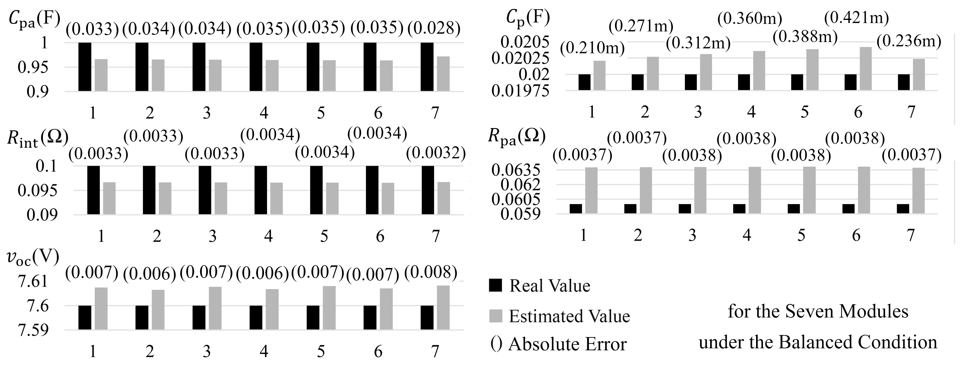
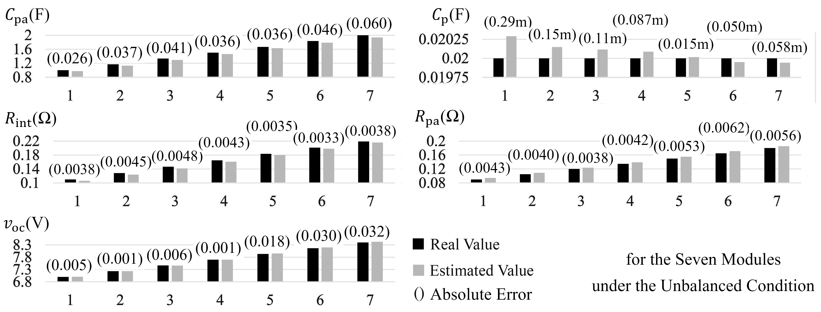
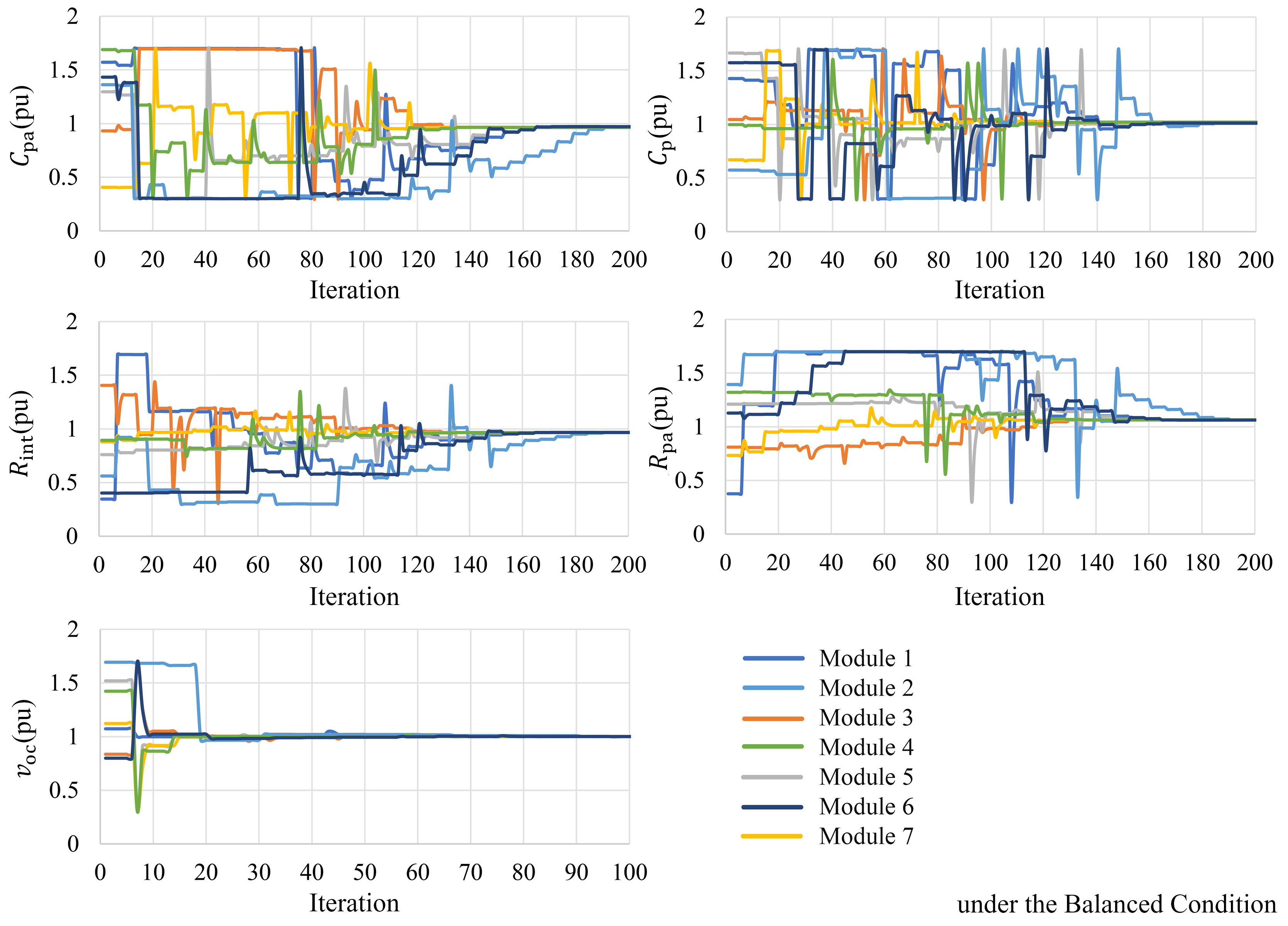
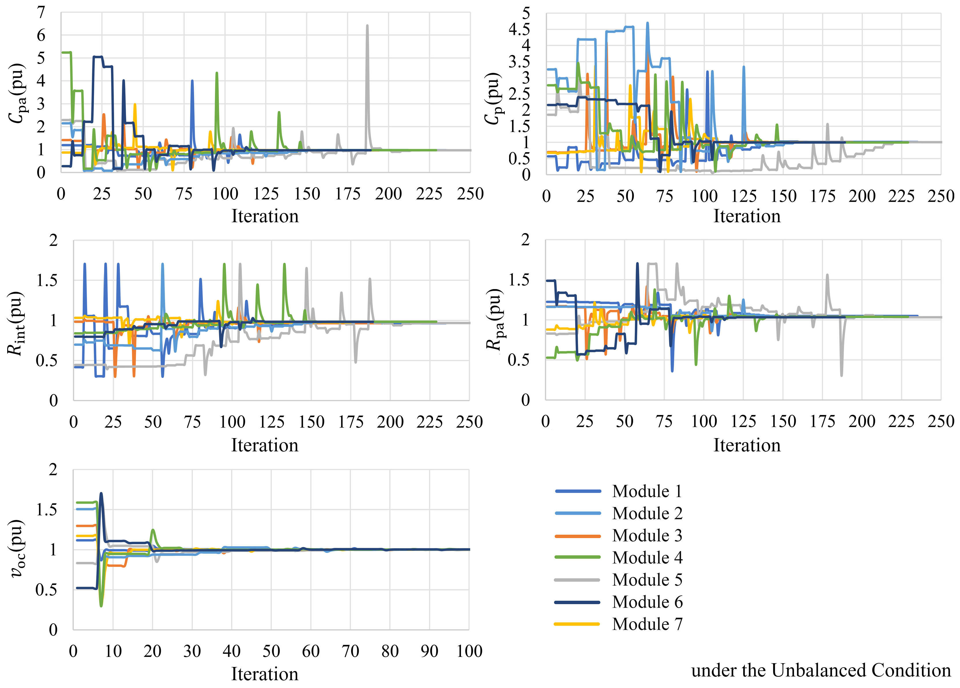
The estimation process can be defined as the following optimization problem:
minimize f [ R int , C p , R pa , C pa , v oc ] subject to l b [ R int , C p , R pa , C pa , v oc ] u b ,
where l b and u b are the lower and upper boundaries of the parameters which are supposed to be estimated. The function f is defined as
f = k = 1 n Δ v j mea ( k ) Δ v j est ( k ) 2
where n is the number of times the falling edge has been detected for the j th module. Δ v j mea ( k ) is the determined voltage of the battery using the proposed decoupling technique, whereas Δ v j est ( k ) is the estimated voltage of the battery according to the estimated parameters.
As this is a simple optimization problem, many techniques can be used [104,105,106]. In this research study, the interior-point method is applied to solve it. As proposing a new optimization method is not the intent of this work, we refer to the literature for further detail [107].

4. Results

The simulation and experimental validation of the proposed method are shown in Figure 5, Figure 6, Figure 7, Figure 8, Figure 9, Figure 10, Figure 11, Figure 12 and Figure 13. Matlab/Simulink serves to simulate a modular reconfigurable battery with seven modules. In practice, the sbRIO-9726 rapid-control prototyping board from National Instrument carries out the voltage modulation, records the modules’ switch states ( S ) and measures the output current, i p , as well as the output voltage, v p . The switching rate of each module is set to 10 kHz, providing a maximum sampling rate of 10 kHz per module. The number of the modules (N), L, R, C are equal to 7, 1 mH, 50 mΩ, and 5 mF, respectively. To determine the true values in the experimental setup, battery modules are discharged with 0.025 C and the terminal voltage dynamics are constantly recorded. At extremely low-discharge rates, the terminal voltage of the battery is a good approximation of the open-circuit voltage after relaxation. Moreover, the terminal voltage is measured before and after the experiment when the batteries have reached equilibrium to determine the exact SOC of the modules. In this manner, the parameter sets of the internal resistance and the RC network parameters of the batteries, according to Figure 3, are separately derived through pulsed current at different SOCs and current amplitudes.
Figure 5 shows an example of the output voltages of the modules for one complete switching cycle. It intuitively shows how they are combined to form the output voltage of the pack. Using the phase-shifted PWM, the output voltage of the pack is N-times the switching rate of each module. The negative and positive edges of the modules’ voltages is clear on the profile of the pack’s voltage. The voltages of the modules are approximately 8 V to 8.2 V, which are normalized for simplicity. The output voltage of the pack at each instant is the sum of all the modules’ voltages. The time division in Figure 5 is 10 μs. The normalized voltage of the modules can approximate their corresponding state at each instance. As the module toggles from S j = 1 to S j = 0 , the decoupling algorithm detects the falling edges in the vector S and records a new sample for the j th module. The sampling instances are marked with red arrows in Figure 5.
The complete implemented process, from measuring the output voltage of the system to creating individual voltage profiles of each module, is shown in Figure 6. The estimation of the ECM conventionally is performed using pulse charging approaches, here, the load is changed to create an external disturbance for the system. After the decoupling procedure, as the voltage and current of the whole system ( i p and v p ) contain a high level of noise, it is possible to reduce the noise level using a digital low-pass filter as long as the added delay due to the denoising procedure is negligible in comparison to the ECM time constants. The following equation offers a typical example used to reduce the switching noises of the measured current i p at instant k
i p ( k ) = 1 2 q + 1 a = q q i p ( k + a ) , v p ( k ) = 1 2 q + 1 a = q q v p ( k + a ) .
For example, a q value of two means the output of the denoising function at the k th sample is the average value of the same sample along with the two samples before and after the main sample. In Figure 6, the actual and denoised profiles of the modules’ voltages are depicted in the bottom left corner, respectively, in gray and blue, which clearly show the improved waveforms.
To study the accuracy of the estimations using the determined profiles, two systems with balanced and imbalanced modules are considered. Table 1 depicts the main parameters of the systems. In the case of imbalanced modules, each module has completely different parameters ( ± 50 % ) to test the convergence of the system.
Figure 7 shows the estimation results for the ECM parameters of balanced modules ( R int , C p , R pa , C pa , v oc ) using the resulted profiles through the decoupling method. Similarly, Figure 8 shows the results for the imbalanced scenario. The chart shown for each parameter contains the estimated value, the real value, and the absolute error for every module.
The absolute estimation error is calculated as:
E = | X mea X est | .
The estimation error for all the parameters are shown in Figure 7 and Figure 8 are below 4% which authenticate the usability of the derived voltage and current profiles for parameter estimation.
In both cases, the errors for estimation of the capacitors are well below 3%. Additionally, the absolute errors for the estimated resistances are less than 6 mΩ. Additionally, there is no change in the accuracy of estimations for the imbalanced system compared to the balanced one.
The estimation results for each iteration of the optimization process for the five parameters are presented in Figure 9 and Figure 10. The initial estimations of the parameters are selected randomly with a ± 50 % uncertainty boundary. The estimated open-circuit voltage rapidly converges to the true value after a few iterations, but as the other two RC networks are relatively co-dependent, more iterations are required for the parameters to converge. As the depicted values are normalized in Figure 9 and Figure 10, a result of one means the estimation is correctly converged. The optimization stops when there is no visible improvement in the cost value. It should be mentioned that the optimization process does not need to be online and can be completed during the idle intervals of the controller or even be off-loaded to the cloud services, but that falls outside the real focus of this paper [108].
Three scenarios help in evaluating the ability of the proposed estimator under different conditions:
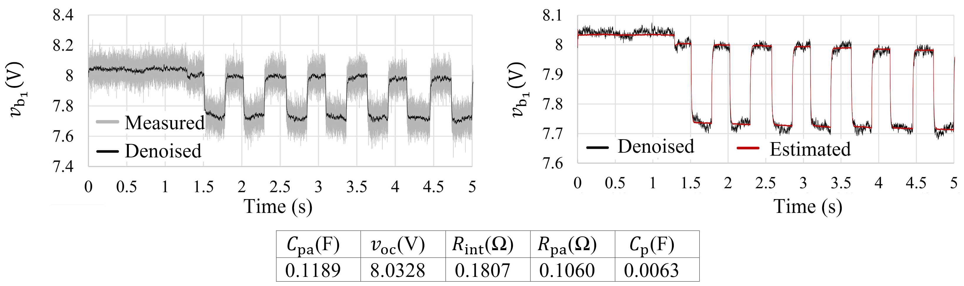
  • The first scenario investigates the behavior of a balanced system where all the modules have relatively similar states (their SOC and SOH as a case in point) and parameters. There are only small inevitable inherent tolerances among their parameters due to manufacturing tolerances.
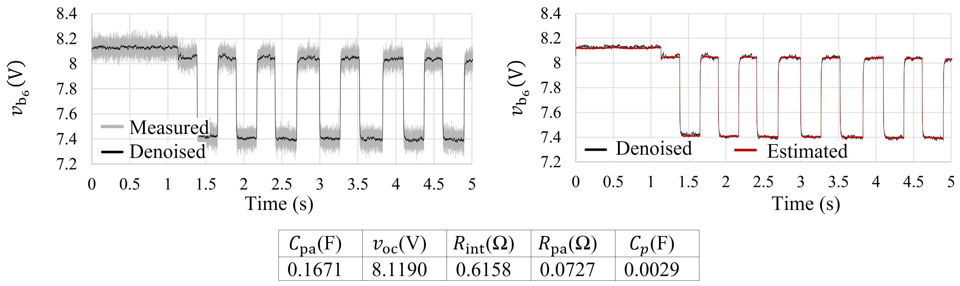
  • In the second scenario, the uniform parameters of the modules are disturbed to simulate a possible imbalance in the system. The ohmic resistance of the sixth battery module ( R int 6 ) is intentionally increased by externally connecting an extra 0.43 Ω resistance in series to the battery. The added ohmic resistance can emulate an aged or possibly faulty battery. Additionally, f sw is changed from 10 kHz to 1 kHz to study the effect of sampling frequency. Changing the battery resistance challenges the ability of the proposed technique to track the asymmetric voltage profiles and evaluate the estimation accuracy for parameters which are beyond normal ranges.
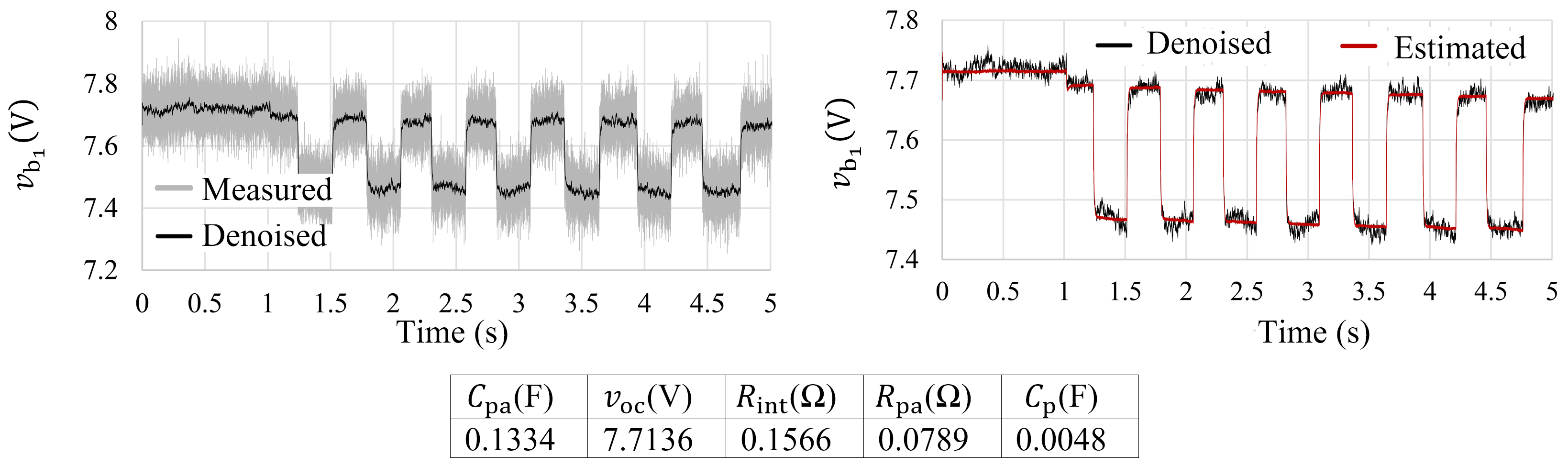
  • The third scenario focuses on existence of imbalance in the modules’ voltages. Therefore, battery modules 2 to 7 are charged to 8 V, whereas the first module is manually discharged to a lower open-circuit voltage (approximately 7.7 V). As a result of a higher charge depletion, other ECM parameters of Module One also change slightly. This scenario can emulate a SOC imbalance in the system, which can challenge the ability of the proposed decoupling technique to distinguish the profiles of different modules. Moreover, in the last two scenarios, estimation results of the other modules remain similar, showing that an existing imbalance in one module does not significantly impact the accuracy of the decoupling method for other modules.
The relevant experimental results for each scenario are shown in Figure 11, Figure 12 and Figure 13, respectively. For each of them, the voltage profile of one of the modules (one, six, and one, respectively) is measured, denoised, and then plotted on the left side. Concurrently, the voltage profile of each module is derived and the parameters are estimated according to the derived profile. Afterwards, the corresponding output battery voltage are calculated based on the estimated ECM parameters. On the right side of each figure, the measured waveform is compared with the calculated one based on the estimated parameters. The matching results confirm the feasibility of the proposed decoupling technique.
The tables of Figure 11, Figure 12 and Figure 13 show the measured parameters of the corresponding battery modules using the proposed decoupling technique. As seen, the estimated ohmic resistance in the second scenario is clearly increased. This confirms the authenticity of the results using the proposed method. Similarly, the open circuit voltage of the module in the third scenario is correctly estimated.

5. Conclusions

Proposing a feasible solution to determine the voltage and current profiles of modules for parameter estimation purposes in a reconfigurable battery is the main purpose of this paper. After detailed modeling and analysis of the reconfigurable batteries’ operations, this paper proposes a decoupling technique that can easily be integrated into the monitoring routine. The resulting profiles for each module can be used to estimate the ECM parameters of the batteries with any state-of-the-art estimation technique. Conventionally, the estimation is accomplished based on the direct measurement at the module terminals, which requires a high number of sensors and a high-bandwidth communication interface, increasing the cost and complexity of the system. The proposed decoupling algorithm does not need any measurement at the module terminals and only uses the already available sensors (system-level measurements) at the output of the system. Therefore, the number of sensors compared to the conventional technique is decreased from 2N + 2 to only two. Additionally, no further communication between the controller and the modules is necessary, which reduces the constraints on the communication interface. The proposed concept can easily be implemented, reducing the system cost and improving the system’s robustness. In addition to the advantages, the method can only estimate the time-constants that are relatively larger than the switching cycle of the modules. Therefore, it cannot be applied to estimate the sub-millisecond time constants of the battery. However, these time constants are rarely utilized in a BMS for estimating the module parameters. Increasing the band-width of the decoupling technique is an interesting goal that warrants further study as a future work. Additionally, switching noise can have a minor effect on the accuracy of the voltage and current profiles, but it can be mitigated through appropriate digital filters, e.g., Kalman filters. The practical results as well as the simulations confirm that the decoupling algorithm works properly. Combined with a suitable estimation technique, the decoupled voltage, and current profiles achieve very good accuracy; the estimation algorithm can accurately calculate the parameters and converge to the desired values.

Author Contributions

Conceptualization and methodology, N.T.; validation, N.T., J.D. and M.B.; formal analysis, N.T. and M.B.; writing—original draft preparation, J.D. and M.B.; writing—review and editing, N.T., A.K., H.S. and S.G.; supervision, N.T.; project administration, S.G. and H.S. All authors have read and agreed to the published version of the manuscript.

Funding

The authors acknowledge the financial support by the Federal Ministry of Education and Research of Germany in the project “Open6GHub” (grant number: 16KISK004).

Data Availability Statement

Not applicable.

Conflicts of Interest

The authors declare no conflict of interest.

Abbreviations

The following abbreviations are used in this manuscript:
EVElectric Vehicle
BMSBattery Management System
ECMEquivalent Circuit Model
SOCState Of Charges
SOHState Of Health
DCDirect Current
ACAlternating Current
MMCsModular Multilevel Converters
OCVsOpen-Circuit Voltages
RCResistance-Capacitance
FETsField-Effect Transistors
PWMPulse-Width Modulation
MOSFETsMetal-Oxide-Semiconductor Field-Effect Transistors
IGBTsInsulated-Gate Bipolar Transistors
FPGAField-Programmable Gate Array

References

  1. Buberger, J.; Kersten, A.; Kuder, M.; Eckerle, R.; Weyh, T.; Thiringer, T. Total CO2-equivalent life-cycle emissions from commercially available passenger cars. Renew. Sustain. Energy Rev. 2022, 159, 112158. [Google Scholar] [CrossRef]
  2. Fassio, E.; Ciociola, A.; Giordano, D.; Noussan, M.; Vassio, L.; Mellia, M. Environmental and Economic Comparison of ICEV and EV in Car Sharing. In Proceedings of the 2021 IEEE International Intelligent Transportation Systems Conference (ITSC), Indianapolis, IN, USA, 19–22 September 2021; pp. 1621–1626. [Google Scholar] [CrossRef]
  3. Fang, J.; Zhang, R.; Li, H.; Tang, Y. Frequency Derivative-Based Inertia Enhancement by Grid-Connected Power Converters with a Frequency-Locked-Loop. IEEE Trans. Smart Grid 2019, 10, 4918–4927. [Google Scholar] [CrossRef]
  4. Fang, J.; Li, H.; Tang, Y.; Blaabjerg, F. On the Inertia of Future More-Electronics Power Systems. IEEE J. Emerg. Sel. Top. Power Electron. 2019, 7, 2130–2146. [Google Scholar] [CrossRef]
  5. Vermeer, W.; Mouli, G.R.C.; Bauer, P. A Comprehensive Review on the Characteristics and Modelling of Lithium-ion Battery Ageing. IEEE Trans. Transp. Electrif. 2021, 8, 2205–2232. [Google Scholar] [CrossRef]
  6. He, C.; Zhu, J.; Li, S.; Chen, Z.; Wu, W. Sizing and Locating Planning of EV Centralized-Battery-Charging-Station Considering Battery Logistics System. IEEE Trans. Ind. Appl. 2022, 58, 5184–5197. [Google Scholar] [CrossRef]
  7. Hussain, A.; Bui, V.H.; Kim, H.M. Optimal Sizing of Battery Energy Storage System in a Fast EV Charging Station Considering Power Outages. IEEE Trans. Transp. Electrif. 2020, 6, 453–463. [Google Scholar] [CrossRef]
  8. Gao, F.; Gu, X.; Ma, Z.; Zhang, C. Redistributed Pulsewidth Modulation of MMC Battery Energy Storage System Under Submodule Fault Condition. IEEE Trans. Power Electron. 2020, 35, 2284–2294. [Google Scholar] [CrossRef]
  9. Salari, O.; Zaad, K.H.; Bakhshai, A.; Jain, P. Reconfigurable hybrid energy storage system for an electric vehicle DC–AC inverter. IEEE Trans. Power Electron. 2020, 35, 12846–12860. [Google Scholar] [CrossRef]
  10. Chen, P.; Xiao, F.; Liu, J.; Zhu, Z.; Ren, Q. Unbalanced operation principle and fast balancing charging strategy of a cascaded modular multilevel converter–bidirectional dc–dc converter in the shipboard applications. IEEE Trans. Transp. Electrif. 2020, 6, 1265–1278. [Google Scholar] [CrossRef]
  11. Ronanki, D.; Williamson, S.S. Modular Multilevel Converters for Transportation Electrification: Challenges and Opportunities. IEEE Trans. Transp. Electrif. 2018, 4, 399–407. [Google Scholar] [CrossRef]
  12. Zhou, L.; Zheng, Y.; Ouyang, M.; Lu, L. A study on parameter variation effects on battery packs for electric vehicles. J. Power Sources 2017, 364, 242–252. [Google Scholar] [CrossRef]
  13. Xiong, R.; Yang, R.; Chen, Z.; Shen, W.; Sun, F. Online Fault Diagnosis of External Short Circuit for Lithium-Ion Battery Pack. IEEE Trans. Ind. Electron. 2020, 67, 1081–1091. [Google Scholar] [CrossRef]
  14. Lin, T.; Chen, Z.; Zheng, C.; Huang, D.; Zhou, S. Fault Diagnosis of Lithium-Ion Battery Pack Based on Hybrid System and Dual Extended Kalman Filter Algorithm. IEEE Trans. Transp. Electrif. 2021, 7, 26–36. [Google Scholar] [CrossRef]
  15. Andrea, D. Battery Management Systems for Large Lithium-Ion Battery Packs; Artech House: Norwood, MA, USA, 2010. [Google Scholar]
  16. Uzair, M.; Abbas, G.; Hosain, S. Characteristics of Battery Management Systems of Electric Vehicles with Consideration of the Active and Passive Cell Balancing Process. World Electr. Veh. J. 2021, 12, 120. [Google Scholar] [CrossRef]
  17. Naguib, M.; Kollmeyer, P.; Emadi, A. Lithium-Ion Battery Pack Robust State of Charge Estimation, Cell Inconsistency, and Balancing: Review. IEEE Access 2021, 9, 50570–50582. [Google Scholar] [CrossRef]
  18. Hu, X.; Xu, L.; Lin, X.; Pecht, M. Battery lifetime prognostics. Joule 2020, 4, 310–346. [Google Scholar] [CrossRef]
  19. Istardi, D.; Putra, I.Z. The Weakest Cell Identification in Li-Ion battery packs using Discharging Technique Performance. In Proceedings of the 2018 International Conference on Applied Engineering (ICAE), Batam, Indonesia, 3–4 October 2018; pp. 1–4. [Google Scholar] [CrossRef]
  20. Afonso, J.L.; Tanta, M.; Pinto, J.G.O.; Monteiro, L.F.; Machado, L.; Sousa, T.J.; Monteiro, V. A Review on Power Electronics Technologies for Power Quality Improvement. Energies 2021, 14, 8585. [Google Scholar] [CrossRef]
  21. He, L.; Yang, Z.; Gu, Y.; Liu, C.; He, T.; Shin, K.G. SoH-Aware Reconfiguration in Battery Packs. IEEE Trans. Smart Grid 2018, 9, 3727–3735. [Google Scholar] [CrossRef]
  22. Balachandran, A.; Jonsson, T.; Eriksson, L. Design and Analysis of Battery-Integrated Modular Multilevel Converters for Automotive Powertrain Applications. In Proceedings of the 2021 23rd European Conference on Power Electronics and Applications (EPE’21 ECCE Europe), Novi Sad, Serbia, 28–30 October 2021; pp. P.1–P.12. [Google Scholar] [CrossRef]
  23. Kacetl, J.; Fang, J.; Kacetl, T.; Tashakor, N.; Goetz, S. Design and Analysis of Modular Multilevel Reconfigurable Battery Converters for Variable Bus Voltage Powertrains. IEEE Trans. Power Electron. 2022, 38, 130–142. [Google Scholar] [CrossRef]
  24. Ma, Z.; Gao, F.; Gu, X.; Li, N.; Niu, D. An Online SOH Testing Method of MMC Battery Energy Storage System. In Proceedings of the 2018 IEEE 19th Workshop on Control and Modeling for Power Electronics (COMPEL), Padova, Italy, 25–28 June 2018; pp. 1–7. [Google Scholar] [CrossRef]
  25. De Simone, D.; Piegari, L. Modular multilevel converters for battery electric vehicles: Variable dc voltage control to optimize battery lifetime. In Proceedings of the 2020 IEEE 14th International Conference on Compatibility, Power Electronics and Power Engineering (CPE-POWERENG), Setúbal, Portugal, 8–10 July 2020; Volume 1, pp. 137–142. [Google Scholar] [CrossRef]
  26. Qiu, S.; Shi, B. An Enhanced Battery Interface of MMC-BESS. In Proceedings of the 2019 IEEE 10th International Symposium on Power Electronics for Distributed Generation Systems (PEDG), Xi’an, China, 3–6 June 2019; pp. 434–439. [Google Scholar] [CrossRef]
  27. Gao, F.; Zhang, L.; Zhou, Q.; Chen, M.; Xu, T.; Hu, S. State-of-charge balancing control strategy of battery energy storage system based on modular multilevel converter. In Proceedings of the 2014 IEEE Energy Conversion Congress and Exposition (ECCE), Pittsburgh, PA, USA, 14–18 September 2014; pp. 2567–2574. [Google Scholar] [CrossRef]
  28. Ma, Z.; Gao, F.; Gu, X.; Li, N.; Wu, Q.; Wang, X.; Wang, X. Multilayer SOH Equalization Scheme for MMC Battery Energy Storage System. IEEE Trans. Power Electron. 2020, 35, 13514–13527. [Google Scholar] [CrossRef]
  29. Altaf, F.; Egardt, B.; Johannesson Mårdh, L. Load Management of Modular Battery Using Model Predictive Control: Thermal and State-of-Charge Balancing. IEEE Trans. Control Syst. Technol. 2017, 25, 47–62. [Google Scholar] [CrossRef]
  30. Soong, T.; Lehn, P.W. Assessment of Fault Tolerance in Modular Multilevel Converters with Integrated Energy Storage. IEEE Trans. Power Electron. 2016, 31, 4085–4095. [Google Scholar] [CrossRef]
  31. Hillers, A.; Biela, J. Fault-tolerant operation of the modular multilevel converter in an energy storage system based on split batteries. In Proceedings of the 2014 16th European Conference on Power Electronics and Applications, Lappeenranta, Finland, 26–28 August 2014; pp. 1–8. [Google Scholar] [CrossRef]
  32. Quraan, M.; Tricoli, P.; D’Arco, S.; Piegari, L. Efficiency Assessment of Modular Multilevel Converters for Battery Electric Vehicles. IEEE Trans. Power Electron. 2017, 32, 2041–2051. [Google Scholar] [CrossRef]
  33. Singer, A.; Helling, F.; Weyh, T.; Jungbauer, J.; Pfisterer, H.J. Modular multilevel parallel converter based split battery system (M2B) for stationary storage applications. In Proceedings of the 2017 19th European Conference on Power Electronics and Applications (EPE’17 ECCE Europe), Warsaw, Poland, 11–14 September 2017; pp. P.1–P.10. [Google Scholar] [CrossRef]
  34. Ma, Z.; Gao, F.; Zhang, C.; Li, W.; Niu, D. Variable DC-Link Voltage Regulation of Single-Phase MMC Battery Energy-Storage System for Reducing Additional Charge Throughput. IEEE Trans. Power Electron. 2021, 36, 14267–14281. [Google Scholar] [CrossRef]
  35. Fonseca, J.M.L.; Reddy, S.R.P.; Rajashekara, K.; Potti, K.R.R. Reduced Capacitor Energy Requirements in Battery Energy Storage Systems based on Modular Multilevel Converters. IEEE Trans. Ind. Appl. 2022, 58, 7608–7619. [Google Scholar] [CrossRef]
  36. Guo, P.; Xu, Q.; Yue, Y.; Ma, F.; He, Z.; Luo, A.; Guerrero, J.M. Analysis and Control of Modular Multilevel Converter with Split Energy Storage for Railway Traction Power Conditioner. IEEE Trans. Power Electron. 2020, 35, 1239–1255. [Google Scholar] [CrossRef]
  37. Zhao, F.; Xiao, G.; Zhu, T.; Zhao, T.; Zheng, X.; Wu, Z. Harmonic Analysis and Suppression Method of Output Current Distortion for Medium-Voltage Motor Drives with Modular Multilevel Converter. IEEE Trans. Power Electron. 2020, 35, 744–759. [Google Scholar] [CrossRef]
  38. Thakur, S.S.; Odavic, M.; Allu, A.; Zhu, Z.Q.; Atallah, K. Theoretical Harmonic Spectra of PWM Waveforms Including DC Bus Voltage Ripple—Application to a Low-Capacitance Modular Multilevel Converter. IEEE Trans. Power Electron. 2020, 35, 9291–9305. [Google Scholar] [CrossRef]
  39. Wang, Y.; Aksoz, A.; Geury, T.; El Baghdadi, M.; Hegazy, O. Performance Enhancement of a Battery-Grid Connected SiC MMC for DC Microgrid Systems. In Proceedings of the 2021 Sixteenth International Conference on Ecological Vehicles and Renewable Energies (EVER), Monte-Carlo, Monaco, 5–7 May 2021; pp. 1–6. [Google Scholar] [CrossRef]
  40. Mittal, N.; Singh, B.; Singh, S.; Dixit, R.; Kumar, D. Multilevel inverters: A literature survey on topologies and control strategies. In Proceedings of the 2012 2nd International Conference on Power, Control and Embedded Systems, Allahabad, India, 17–19 December 2012; pp. 1–11. [Google Scholar] [CrossRef]
  41. Fang, J.; Blaabjerg, F.; Liu, S.; Goetz, S.M. A review of multilevel converters with parallel connectivity. IEEE Trans. Power Electron. 2021, 36, 12468–12489. [Google Scholar] [CrossRef]
  42. Chen, J.; Jiang, D.; Sun, W.; Pei, X. Common-Mode Voltage Reduction Scheme for MMC with Low Switching Frequency in AC–DC Power Conversion System. IEEE Trans. Ind. Inform. 2021, 18, 278–287. [Google Scholar] [CrossRef]
  43. Priya, M.; Ponnambalam, P.; Muralikumar, K. Modular-multilevel converter topologies and applications—A review. IET Power Electron. 2019, 12, 170–183. [Google Scholar] [CrossRef]
  44. Debnath, S.; Qin, J.; Bahrani, B.; Saeedifard, M.; Barbosa, P. Operation, control, and applications of the modular multilevel converter: A review. IEEE Trans. Power Electron. 2014, 30, 37–53. [Google Scholar] [CrossRef]
  45. Kersten, A.; Kuder, M.; Grunditz, E.; Geng, Z.; Wikner, E.; Thiringer, T.; Weyh, T.; Eckerle, R. Inverter and Battery Drive Cycle Efficiency Comparisons of CHB and MMSP Traction Inverters for Electric Vehicles. In Proceedings of the 2019 21st European Conference on Power Electronics and Applications (EPE’19 ECCE Europe), Genova, Italy, 3–5 September 2019; pp. P.1–P.12. [Google Scholar] [CrossRef]
  46. Dai, S.; Zhang, F.; Zhao, X. Series-connected battery equalization system: A systematic review on variables, topologies, and modular methods. Int. J. Energy Res. 2021, 45, 19709–19728. [Google Scholar] [CrossRef]
  47. Arabsalmanabadi, B.; Tashakor, N.; Zhang, Y.; Al-Haddad, K.; Goetz, S. Parameter estimation of batteries in MMCs with parallel connectivity using PSO. In Proceedings of the IECON 2021—47th Annual Conference of the IEEE Industrial Electronics Society, Toronto, ON, Canada, 13–16 October 2021; pp. 1–6. [Google Scholar]
  48. Raman, S.R.; Xue, X.; Cheng, K.E. Review of charge equalization schemes for Li-ion battery and super-capacitor energy storage systems. In Proceedings of the 2014 International Conference on Advances in Electronics Computers and Communications, Bangalore, India, 10–11 October 2014; pp. 1–6. [Google Scholar]
  49. Lu, L.; Han, X.; Li, J.; Hua, J.; Ouyang, M. A review on the key issues for lithium-ion battery management in electric vehicles. J. Power Sources 2013, 226, 272–288. [Google Scholar] [CrossRef]
  50. Tan, X.; Tan, Y.; Zhan, D.; Yu, Z.; Fan, Y.; Qiu, J.; Li, J. Real-time state-of-health estimation of lithium-ion batteries based on the equivalent internal resistance. IEEE Access 2020, 8, 56811–56822. [Google Scholar] [CrossRef]
  51. Cao, J.; Emadi, A. Batteries Need Electronics. IEEE Ind. Electron. Mag. 2011, 5, 27–35. [Google Scholar] [CrossRef]
  52. Givi, H.; Hosseini, E.; Farjah, E. Estimation of batteries voltages and resistances in modular multilevel converter with half-bridge modules using modified PSO algorithm. In Proceedings of the 2021 12th Power Electronics, Drive Systems, and Technologies Conference (PEDSTC), Babol, Iran, 2–4 February 2021; pp. 1–7. [Google Scholar]
  53. Poblete, P.; Pizarro, G.; Droguett, G.; Núñez, F.; Judge, P.D.; Pereda, J. Distributed Neural Network Observer for Submodule Capacitor Voltage Estimation in Modular Multilevel Converters. IEEE Trans. Power Electron. 2022, 37, 10306–10318. [Google Scholar] [CrossRef]
  54. Kacetl, T.; Kacetl, J.; Fang, J.; Jaensch, M.; Goetz, S. Degradation-Reducing Control for Dynamically Reconfigurable Batteries. arXiv 2022, arXiv:2202.11757. [Google Scholar]
  55. Konstantinou, G.; Wickramasinghe, H.R.; Townsend, C.D.; Ceballos, S.; Pou, J. Estimation methods and sensor reduction in modular multilevel converters: A review. In Proceedings of the 2018 8th International Conference on Power and Energy Systems (ICPES), Galadari Hotel, Colombo, Sri Lanka, 21–22 December 2018; pp. 23–28. [Google Scholar]
  56. da Silva, G.S.; Vieira, R.P.; Rech, C. Discrete-time sliding-mode observer for capacitor voltage control in modular multilevel converters. IEEE Trans. Ind. Electron. 2017, 65, 876–886. [Google Scholar] [CrossRef]
  57. Nademi, H.; Das, A.; Norum, L.E. Modular multilevel converter with an adaptive observer of capacitor voltages. IEEE Trans. Power Electron. 2014, 30, 235–248. [Google Scholar] [CrossRef]
  58. Wang, Z.; Peng, L. Grouping capacitor voltage estimation and fault diagnosis with capacitance self-updating in modular multilevel converters. IEEE Trans. Power Electron. 2020, 36, 1532–1543. [Google Scholar] [CrossRef]
  59. Rong, F.; Gong, X.; Li, X.; Huang, S. A new voltage measure method for MMC based on sample delay compensation. IEEE Trans. Power Electron. 2017, 33, 5712–5723. [Google Scholar] [CrossRef]
  60. Abushafa, O.; Gadoue, S.; Dhaidah, M.; Aktinson, D. Capacitor voltage estimation in modular multilevel converters using a Kalman filter algorithm. In Proceedings of the 2015 IEEE International Conference on Industrial Technology (ICIT), Seville, Spain, 17–19 March 2015; pp. 3016–3021. [Google Scholar]
  61. Abushafa, O.S.H.M.; Dahidah, M.S.A.; Gadoue, S.M.; Atkinson, D.J. Submodule Voltage Estimation Scheme in Modular Multilevel Converters with Reduced Voltage Sensors Based on Kalman Filter Approach. IEEE Trans. Ind. Electron. 2018, 65, 7025–7035. [Google Scholar] [CrossRef]
  62. Chakraborty, R.; Samantaray, J.; Dey, A.; Chakrabarty, S. Capacitor Voltage Estimation of MMC Using a Discrete-Time Sliding Mode Observer Based on Discrete Model Approach. IEEE Trans. Ind. Appl. 2022, 58, 494–504. [Google Scholar] [CrossRef]
  63. Asoodar, M.; Nahalparvari, M.; Danielsson, C.; Söderström, R.; Nee, H.P. Online Health Monitoring of DC-Link Capacitors in Modular Multilevel Converters for FACTS and HVDC Applications. IEEE Trans. Power Electron. 2021, 36, 13489–13503. [Google Scholar] [CrossRef]
  64. Purkayastha, B.; Bhattacharya, T. Simplified Approach for Acquisition of Submodule Capacitor Voltages of the Modular Multilevel Converter Using Low Sampling Rate Sensing and Estimation. IEEE Trans. Power Electron. 2022, 37, 13428–13438. [Google Scholar] [CrossRef]
  65. Han, W.; Zou, C.; Zhou, C.; Zhang, L. Estimation of Cell SOC Evolution and System Performance in Module-Based Battery Charge Equalization Systems. IEEE Trans. Smart Grid 2019, 10, 4717–4728. [Google Scholar] [CrossRef]
  66. Chen, H.; Tian, E.; Wang, L. State-of-Charge Estimation of Lithium-Ion Batteries Subject to Random Sensor Data Unavailability: A Recursive Filtering Approach. IEEE Trans. Ind. Electron. 2021, 69, 5175–5184. [Google Scholar] [CrossRef]
  67. Wang, Q.; Wang, Z.; Zhang, L.; Liu, P.; Zhang, Z. A novel consistency evaluation method for series-connected battery systems based on real-world operation data. IEEE Trans. Transp. Electrif. 2020, 7, 437–451. [Google Scholar] [CrossRef]
  68. Chen, L.; Ding, Y.; Wang, H.; Wang, Y.; Liu, B.; Wu, S.; Li, H.; Pan, H. Online Estimating State of Health of Lithium-Ion Batteries Using Hierarchical Extreme Learning Machine. IEEE Trans. Transp. Electrif. 2021, 8, 965–975. [Google Scholar] [CrossRef]
  69. Xiong, R.; Li, L.; Tian, J. Towards a smarter battery management system: A critical review on battery state of health monitoring methods. J. Power Sources 2018, 405, 18–29. [Google Scholar] [CrossRef]
  70. Wang, Y.; Tian, J.; Sun, Z.; Wang, L.; Xu, R.; Li, M.; Chen, Z. A comprehensive review of battery modeling and state estimation approaches for advanced battery management systems. Renew. Sustain. Energy Rev. 2020, 131, 110015. [Google Scholar] [CrossRef]
  71. Cen, Z.; Kubiak, P. Lithium-ion battery SOC/SOH adaptive estimation via simplified single particle model. Int. J. Energy Res. 2020, 44, 12444–12459. [Google Scholar] [CrossRef]
  72. Huang, S.C.; Tseng, K.H.; Liang, J.W.; Chang, C.L.; Pecht, M.G. An online SOC and SOH estimation model for lithium-ion batteries. Energies 2017, 10, 512. [Google Scholar] [CrossRef]
  73. Barré, A.; Deguilhem, B.; Grolleau, S.; Gérard, M.; Suard, F.; Riu, D. A review on lithium-ion battery ageing mechanisms and estimations for automotive applications. J. Power Sources 2013, 241, 680–689. [Google Scholar] [CrossRef]
  74. Carkhuff, B.G.; Demirev, P.A.; Srinivasan, R. Impedance-Based Battery Management System for Safety Monitoring of Lithium-Ion Batteries. IEEE Trans. Ind. Electron. 2018, 65, 6497–6504. [Google Scholar] [CrossRef]
  75. Shen, M.; Gao, Q. A review on battery management system from the modeling efforts to its multiapplication and integration. Int. J. Energy Res. 2019, 43, 5042–5075. [Google Scholar] [CrossRef]
  76. Kersten, A.; Kuder, M.; Han, W.; Thiringer, T.; Lesnicar, A.; Weyh, T.; Eckerle, R. Online and On-Board Battery Impedance Estimation of Battery Cells, Modules or Packs in a Reconfigurable Battery System or Multilevel Inverter. In Proceedings of the IECON 2020 The 46th Annual Conference of the IEEE Industrial Electronics Society, Singapore, 18–21 October 2020; pp. 1884–1891. [Google Scholar] [CrossRef]
  77. Balachandran, A.; Jonsson, T.; Eriksson, L.; Larsson, A. Experimental Evaluation of Battery Impedance and Submodule Loss Distribution for Battery Integrated Modular Multilevel Converters. In Proceedings of the 2022 24th European Conference on Power Electronics and Applications (EPE’22 ECCE Europe), Hannover, Germany, 5–9 September 2022; pp. 1–10. [Google Scholar]
  78. Tashakor, N.; Arabsalmanabadi, B.; Naseri, F.; Goetz, S. Low-Cost Parameter Estimation Approach for Modular Converters and Reconfigurable Battery Systems Using Dual Kalman Filter. IEEE Trans. Power Electron. 2021, 37, 6323–6334. [Google Scholar] [CrossRef]
  79. Einhorn, M.; Conte, F.V.; Kral, C.; Fleig, J. Comparison, Selection, and Parameterization of Electrical Battery Models for Automotive Applications. IEEE Trans. Power Electron. 2013, 28, 1429–1437. [Google Scholar] [CrossRef]
  80. Meng, J.; Stroe, D.I.; Ricco, M.; Luo, G.; Teodorescu, R. A simplified model-based state-of-charge estimation approach for lithium-ion battery with dynamic linear model. IEEE Trans. Ind. Electron. 2018, 66, 7717–7727. [Google Scholar] [CrossRef]
  81. Xiong, R.; Cao, J.; Yu, Q.; He, H.; Sun, F. Critical review on the battery state of charge estimation methods for electric vehicles. IEEE Access 2017, 6, 1832–1843. [Google Scholar] [CrossRef]
  82. Lelie, M.; Braun, T.; Knips, M.; Nordmann, H.; Ringbeck, F.; Zappen, H.; Sauer, D.U. Battery Management System Hardware Concepts: An Overview. Appl. Sci. 2018, 8, 534. [Google Scholar] [CrossRef]
  83. Pizarro, G.; Poblete, P.; Droguett, G.; Pereda, J.; Núñez, F. Extended Kalman Filtering for Full-State Estimation and Sensor Reduction in Modular Multilevel Converters. IEEE Trans. Ind. Electron. 2022, 70, 1927–1938. [Google Scholar] [CrossRef]
  84. Zhang, W.; Wang, L.; Wang, L.; Liao, C.; Zhang, Y. Joint State-of-Charge and State-of-Available-Power Estimation Based on the Online Parameter Identification of Lithium-Ion Battery Model. IEEE Trans. Ind. Electron. 2022, 69, 3677–3688. [Google Scholar] [CrossRef]
  85. Mukhopadhyay, S.; Usman, H.M.; Rehman, H. Real Time Li-Ion Battery Bank Parameters Estimation via Universal Adaptive Stabilization. IEEE Open J. Control Syst. 2022, 1, 268–293. [Google Scholar] [CrossRef]
  86. Xie, F.; Czogalla, O. Lightweight Parameter Estimation for the Third-Order Lithium-Ion Battery Model Based on Non-iterative Algorithm. In Proceedings of the 2020 IEEE Transportation Electrification Conference & Expo (ITEC), Virtual, 22–26 June 2020; pp. 164–168. [Google Scholar] [CrossRef]
  87. Lee, S.; Mohtat, P.; Siegel, J.B.; Stefanopoulou, A.G.; Lee, J.W.; Lee, T.K. Estimation Error Bound of Battery Electrode Parameters with Limited Data Window. IEEE Trans. Ind. Inform. 2020, 16, 3376–3386. [Google Scholar] [CrossRef]
  88. Bhat, C.; Channegowda, J.; Naraharisetti, K. An Improved Equivalent Circuit Parameter Estimation Using Electrochemical Model for Lead-Acid Battery. In Proceedings of the 2022 IEEE Delhi Section Conference (DELCON), Virtual, 11–13 February 2022; pp. 1–4. [Google Scholar] [CrossRef]
  89. Shrivastava, P.; Soon, T.K.; Yamani Bin Idris, M.; Mekhilef, S. Lithium-ion Battery Model Parameter Identification Using Modified Adaptive Forgetting Factor-Based Recursive Least Square Algorithm. In Proceedings of the 2021 IEEE 12th Energy Conversion Congress & Exposition—Asia (ECCE-Asia), Singapore, 24–27 May 2021; pp. 2169–2174. [Google Scholar] [CrossRef]
  90. Tashakor, N.; Arabsalmanabadi, B.; Hosseini, E.; Al-Haddad, K.; Goetz, S. Estimation of Battery Parameters in Cascaded Half-Bridge Converters with Reduced Voltage Sensors. In Proceedings of the 2022 24th European Conference on Power Electronics and Applications (EPE’22 ECCE Europe), Hannover, Germany, 5–9 September 2022; pp. 1–11. [Google Scholar]
  91. He, H.; Xiong, R.; Fan, J. Evaluation of lithium-ion battery equivalent circuit models for state of charge estimation by an experimental approach. Energies 2011, 4, 582–598. [Google Scholar] [CrossRef]
  92. Bessman, A.; Soares, R.; Wallmark, O.; Svens, P.; Lindbergh, G. Aging effects of AC harmonics on lithium-ion cells. J. Energy Storage 2019, 21, 741–749. [Google Scholar] [CrossRef]
  93. Uno, M.; Tanaka, K. Influence of high-frequency charge–discharge cycling induced by cell voltage equalizers on the life performance of lithium-ion cells. IEEE Trans. Veh. Technol. 2011, 60, 1505–1515. [Google Scholar] [CrossRef]
  94. De Jongh, P.; Notten, P. Effect of current pulses on lithium intercalation batteries. Solid State Ionics 2002, 148, 259–268. [Google Scholar] [CrossRef]
  95. Chang, F.; Roemer, F.; Lienkamp, M. Influence of current ripples in cascaded multilevel topologies on the aging of lithium batteries. IEEE Trans. Power Electron. 2020, 35, 11879–11890. [Google Scholar] [CrossRef]
  96. Kacetl, T.; Kacetl, J.; Tashakor, N.; Fang, J.; Goetz, S.M. Bandwidth-Increased Ripple-Mitigating Scheduling Algorithm for Dynamically Reconfigurable Batteries. IEEE Access 2022, 10, 104202–104214. [Google Scholar] [CrossRef]
  97. Kacetl, T.; Kacetl, J.; Tashakor, N.; Goetz, S. A Simplified Model for the Battery Ageing Potential Under Highly Rippled Load. In Proceedings of the 2022 24th European Conference on Power Electronics and Applications (EPE’22 ECCE Europe), Hannover, Germany, 5–9 September 2022; pp. 1–10. [Google Scholar]
  98. Chen, M.; Rincon-Mora, G.A. Accurate electrical battery model capable of predicting runtime and IV performance. IEEE Trans. Energy Convers. 2006, 21, 504–511. [Google Scholar] [CrossRef]
  99. Yazdani, A.; Iravani, R. Voltage-Sourced Converters in Power Systems: Modeling, Control, and Applications; John Wiley & Sons: Hoboken, NJ, USA, 2010. [Google Scholar]
  100. Li, Y.; Wang, Y.; Li, B.Q. Generalized Theory of Phase-Shifted Carrier PWM for Cascaded H-Bridge Converters and Modular Multilevel Converters. IEEE J. Emerg. Sel. Top. Power Electron. 2016, 4, 589–605. [Google Scholar] [CrossRef]
  101. Abdelrahman, A.S.; Erdem, Z.; Attia, Y.; Youssef, M.Z. Wide bandgap devices in electric vehicle converters: A performance survey. Can. J. Electr. Comput. Eng. 2018, 41, 45–54. [Google Scholar] [CrossRef]
  102. Sivkov, O.; Novak, M.; Novak, J. Comparison between Si IGBT and SiC MOSFET Inverters for AC Motor Drive. In Proceedings of the 2018 18th International Conference on Mechatronics-Mechatronika (ME), Brno, Czech Republic, 5–7 December 2018; pp. 1–5. [Google Scholar]
  103. Rogers, M.J.; Motto, E.R.; Steiner, M. Performance comparison of state-of-the-art 300a/1700v si igbt and SiC mosfet power modules. IEEE Power Electron. Mag. 2020, 7, 44–51. [Google Scholar] [CrossRef]
  104. Li, Y.; Zhu, H.; Zheng, J.; Chen, Y. A Multivariate Regression Method for Battery Remaining Capacity Based on Model Parameter Identification. In Proceedings of the 2021 3rd International Academic Exchange Conference on Science and Technology Innovation (IAECST), Guangzhou, China, 10–21 December 2021; pp. 1120–1124. [Google Scholar] [CrossRef]
  105. Ahmed, R.; Rahimifard, S.; Habibi, S. Offline Parameter Identification and SOC Estimation for New and Aged Electric Vehicles Batteries. In Proceedings of the 2019 IEEE Transportation Electrification Conference and Expo (ITEC), Novi, MI, USA, 21 June 2019; pp. 1–6. [Google Scholar] [CrossRef]
  106. Hossain, M.; Haque, M.E.; Arif, M.T. Online Model Parameter and State of Charge Estimation of Li-Ion Battery Using Unscented Kalman Filter Considering Effects of Temperatures and C-Rates. IEEE Trans. Energy Convers. 2022, 37, 2498–2511. [Google Scholar] [CrossRef]
  107. Nocedal, J.; Öztoprak, F.; Waltz, R.A. An interior point method for nonlinear programming with infeasibility detection capabilities. Optim. Methods Softw. 2014, 29, 837–854. [Google Scholar] [CrossRef]
  108. Adhikaree, A.; Kim, T.; Vagdoda, J.; Ochoa, A.; Hernandez, P.J.; Lee, Y. Cloud-based battery condition monitoring platform for large-scale lithium-ion battery energy storage systems using internet-of-things (IoT). In Proceedings of the 2017 IEEE Energy Conversion Congress and Exposition (ECCE), Cincinnati, OH, USA, 1–5 October 2017; pp. 1004–1009. [Google Scholar] [CrossRef]
Figure 1. The modular reconfigurable battery.
Batteries 09 00099 g001
Figure 2. Modes of the j th module.
Batteries 09 00099 g002
Figure 3. Derivation of the electrical model for the modules: (a) actual depiction of a battery with a parallel capacitor, (b) circuit based on the first-order ECM of the battery, (c) first approximation of the ECM, (d) final ECM.
Batteries 09 00099 g003
Figure 4. Flowchart of the decoupling algorithm.
Batteries 09 00099 g004
Figure 5. Output voltages of the seven modules and their summation during the decoupling algorithm.
Batteries 09 00099 g005
Figure 6. The decoupling algorithm and the estimation algorithm.
Batteries 09 00099 g006
Figure 7. Estimation of the five parameters for the seven modules under the balanced condition.
Batteries 09 00099 g007
Figure 8. Estimation of the five parameters for the seven modules under the unbalanced condition.
Batteries 09 00099 g008
Figure 9. Estimation process of the five battery parameters for the seven modules under the balanced condition.
Batteries 09 00099 g009
Figure 10. Estimation process of the five battery parameters for the seven modules under the unbalanced condition.
Batteries 09 00099 g010
Figure 11. Scenario one: measured, denoised, and estimated output voltage of the first module ( v b 1 ).
Batteries 09 00099 g011
Figure 12. Scenario two: measured, denoised, and estimated output voltage of the sixth module ( v b 6 ).
Batteries 09 00099 g012
Figure 13. Scenario three: measured, filtered, and estimated output voltage of the first module ( v b 1 ).
Batteries 09 00099 g013
Table 1. Some important parameters in the simulation and practice.
ParameterValue
N7
m200
T sw = T sampling 10 kHz
C2 mF
L0.2 mH
R0.05 Ω
R Load 5∼40 Ω
v oc 1 7 2.1∼14.28 V
C pa 1 7 0.3∼3.4 F
R int 1 7 0.033∼0.374 Ω
R pa 1 7 0.027∼0.306 Ω
C p 1 7 0.001∼0.034 F
Disclaimer/Publisher’s Note: The statements, opinions and data contained in all publications are solely those of the individual author(s) and contributor(s) and not of MDPI and/or the editor(s). MDPI and/or the editor(s) disclaim responsibility for any injury to people or property resulting from any ideas, methods, instructions or products referred to in the content.

