Article

Nitrogen, Phosphorus Co-Doped Graphite Felt as Highly Efficient Electrode for VO2+/VO2+ Reaction

Beijing Key Laboratory of Bio-inspired Energy Materials and Devices, School of Space and Environment, Beihang University, Beijing 100191, China
*
Authors to whom correspondence should be addressed.
Batteries 2023, 9(1), 40; https://doi.org/10.3390/batteries9010040
Submission received: 1 December 2022 / Revised: 29 December 2022 / Accepted: 3 January 2023 / Published: 5 January 2023
(This article belongs to the Special Issue Promising Redox Flow Batteries)

Abstract

:
All-vanadium redox flow batteries hold promise for the next-generation grid-level energy storage technology in the future. However, the low electrocatalytic activity of initial graphite felt constrains the development of VRFBs. Furthermore, the positive VO2+/VO2+ reaction involves complex multistep processes and more sluggish kinetics than negative V2+/V3+ reaction. Therefore, enhancing the kinetics of positive reaction is especially important. Heteroatom doping is one of the effective strategies for preparing carbon electrodes with high electrocatalytic activity and good stability. Here, a nitrogen, phosphorus co-doped graphite felt is prepared. Nitrogen introduces more negative charge into the carbon lattice due to the higher electronegativity, and more oxygen-containing functional groups will be introduced into the carbon lattice due to phosphorus-doped graphite felt. N, P co-doping provides more adsorption sites for vanadium ions. As a result, nitrogen, phosphorus co-doped graphite felt shows high electrochemical activity and good stability, and the corresponding VRFB presents a good voltage efficiency of 75% at a current density of 300 mA cm−2, which is 11% higher than the pristine graphite felt. During 100 charge/discharge cycles, the energy efficiency and voltage efficiency remain at 84% and 86% under the current density of 150 mA cm−2.

1. Introduction

Renewable energies are a key component of the next-generation energy system. However, renewable energies, such as wind energy and solar energy, need a large-scale energy storage system to achieve stable utilization due to their instability and volatility. Hence, a large-scale energy storage system is an important equipment foundation and a key supporting technology for building next-generation power systems and promoting green and low-carbon transformation of energy [1,2]. Among large-scale energy storage systems, all-vanadium redox flow batteries (VRFBs) have become one of the promising grid-level energy storage technologies because of their advantages of long cycle life, design flexibility, and high safety [3,4,5,6,7,8]. However, the high cost limits the extensive application of VRFB. The cost of a stack is approximately 40% of the total cost [9]. Improving the power density of VRFBs is regarded as an efficient way to lower the unit cost [10]. As one of the key materials of VRFBs, electrode determines the power density and energy efficiency of VRFBs. Carbon felt, carbon paper, carbon cloth, and other carbon-based materials have been widely used as the electrode of VRFBs owing to their excellent conductivity, high stability, and low cost [5,6]. However, the lack of active sites and poor wettability limit their electrocatalytic activity. Besides, a positive VO2+/VO2+ reaction involves complex multistep processes and exhibits more sluggish kinetics compared with a negative reaction. Therefore, various carbon electrode modification strategies have been proposed to enhance positive reaction rates. At present, the reported modification methods for carbon electrodes mainly include acid or thermal treatment, surface etching, modified electrocatalysts, and heteroatom doping. Acid or thermal treatment is the typical approach to introduce more oxygen functional groups on the electrode by oxidation [11,12]. However, excessive oxidation treatment may reduce the conductivity of the electrodes. Surface etching mainly creates holes on the surface of carbon fibers to enhance the electrochemical area of the electrode, such as KOH [13], FexOy [14], Zn(NO3)2 [15], and CO2 [16] etching. However, surface etching of commercial carbon electrodes is faced with the problem of nonadjustable pore size and volume, which makes it difficult to optimize the electrode structure. Introducing electrocatalysts is another effective approach to enhance catalytic activity. The catalysts commonly used in VRFBs are mainly metal compounds (Ta2O5 [17], NiCoO2 [18], Mn3O4 [19], CeO2 [20], W18O49 [21], etc.) and carbon materials (graphene oxide nanoplatelets [22], graphene quantum dot [23], and carbon aerogels [24]). However, the conductivity of the catalyst and the uniformity of the catalyst distribution are problems that need to be solved. In addition, these catalysts are easy to fall off during electrolyte scouring or RFB charging and discharging, which may lead to poor stability. Heteroatom doping is an effective strategy to prepare carbon electrodes with high electrocatalytic activity and reasonable stability. The main doped elements include O, N, B, P, and S [25,26,27,28,29,30]. Nitrogen, as the adjacent element to carbon in the periodic table, has a similar radius to carbon with higher electronegativity [27]. Therefore, the introduction of nitrogen into carbon materials binds amount of negative charges to enhance the adsorption of vanadium ions, and the polarity of carbon–nitrogen bonds can also improve the hydrophilicity of carbon materials [31,32,33]. It has been reported that N-doped carbon materials are promising electrocatalysts for vanadium batteries [28,31,34,35]. For instance, a N-doped porous graphite felt prepared by ZIF-67 modified graphite felt presents a peak power density of 1006 mW cm−2 due to the introduction of mutiscale pores and N-containing functional groups [35]. Phosphorus doping could improve the electrocatalytic activity of carbon electrodes by introducing abundant oxygen-containing functional groups, such as P-O and P=O [36,37]. Moreover, P-doping could also increase the interlayer spacing and stabilize the electrochemical interface between the electrode and the electrolyte [38]. For instance, Li et al. [36] proposed that the P-OH group is the main active site of VO2+/VO2+ electrochemical reaction, and consequently, VRFB using P-doped graphite felt shows a high energy efficiency of 81% at a current density of 200 mA cm−2. Besides, numerous studies have shown that dual-doped carbons have higher electrocatalytic activity than single-element doped carbons [39,40,41], which is mainly due to more active sites and defects by different elements. The above advantages make it possible for a N, P co-doped electrode to be widely used in VRFBs. Some studies have proved that N, P co-doping is an effective approach to improve the electrocatalytic activity of electrodes [42,43]. However, complex processes, poor stability, and toxic raw materials limit their large-scale application.
In this work, a N, P co-doped graphite felt electrode (NPGF) was prepared via a one-step method based on ethylenediamine tetra(methylene phosphonic acid) (EDTMPA), as shown in Scheme 1, and its electrocatalytic activity for vanadium couples was studied. Benefitting from the introduction of abundant nitrogen and phosphorus heteroatoms and oxygen-containing functional groups, NPGF rendered improved electrocatalytic activity for VO2+/VO2+ and excellent stability. The corresponding VRFB exhibited a voltage efficiency of 75% at a current density of 300 mA cm−2 and outstanding stability for 100 charge/discharge cycles.

2. Materials and Methods

2.1. Preparation of the Aqueous Solution of EDTMPA

An amount of 20 mg of EDTMPA powder was dissolved into 20 mL H2O; then the suspension was heated at 120 °C to accelerate EDTMPA dissolution, followed by natural cooling to room temperature.

2.2. Preparation of NPGF

Initial graphite felt (GF) was heated in an air atmosphere at 500 °C for 5 h to form thermally treated graphite felt (TGF) in order to enhance the wettability of GF. Then, TGF was soaked in EDTMPA solution overnight and dried at 60 °C. The samples were treated at 700, 800, and 900 °C for 3 h under nitrogen atmosphere, respectively. Finally, the carbonized electrode was washed with 1.5 M HCl and ultrapure water three times to obtain the NPGF electrode. NPGF was prepared at a different temperature, and the samples were named NPGF-x (x = 700, 800, and 900).

2.3. Characterization of the NPGF

The surface morphology and elemental mapping were characterized by a scanning electron microscope (SEM, ZEISS Sigma 500) with an energy dispersive X-ray spectroscope (EDS). The types and chemical states of elements on the electrode surface were obtained by X-ray photoelectron spectroscopy (XPS, Thermo Escalab 250Xi). Raman spectroscopy was performed to characterize the structural disorder of the electrode materials.

2.4. Electrochemical Characterization

Cyclic voltammetry (CV) was conducted using a CHI760E electrochemical workstation, and electrochemical impedance spectroscopy (EIS) was carried out by a VersaSTAT 4 electrochemical workstation. All electrochemical measurements were conducted in a three-electrode system in the N2 atmosphere at 25.0 ± 1.0 °C, where the as-prepared electrode sample served as the working electrode, the GF and saturated calomel electrode (SCE) were used as counter and reference electrodes, respectively. In CV and EIS measurements, the electrolyte consisted of 0.1 M VOSO4 and 3M H2SO4, the potential ranged from 0 to 1.5 V (vs. SCE), and the scan rates varied from 10 to 50 mV s−1. The EIS was measured over the frequency ranging from 0.01 Hz to 100 kHz.

2.5. Single-Battery Tests

A single battery consists of a negative electrode, a positive electrode and a Nafion®212 membrane with an active area of 2 × 2 cm2. The negative electrolyte was 1.5 M V3+ + 3 M H2SO4, and the positive electrolyte was 1.5 M VOSO4 + 3 M H2SO4. The volumes of positive and negative electrolytes were both 10 mL, and the electrolyte flow rate was 60 mL min−1 controlled by an electric pump (Kamoer New KP). The rate performance was tested under the current density changing from 50 to 300 mA cm−2. The stability of VRFB was tested at 150 mA cm−2 after the rate performance. The cut-off voltage was set at 0.8 and 1.7 V during all battery tests. The electrolyte was inserted with nitrogen gas for 30 min before the battery test and all battery performances were measured using a Neware 5V3A battery test system (Neware, Shenzhen, China) at 25 ± 1.0 °C.

3. Results and Discussion

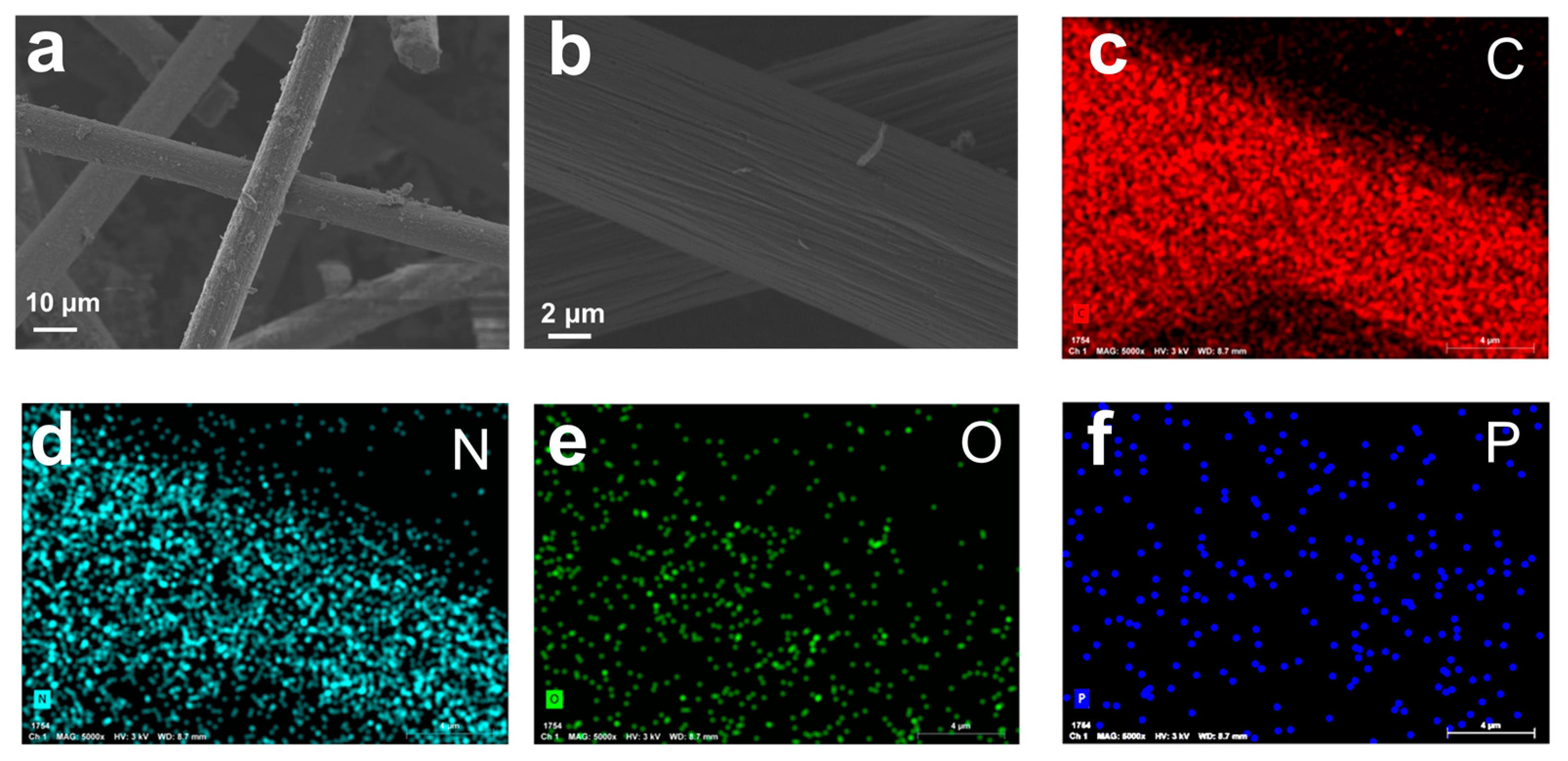
3.1. Structure and Elemental Composition of NPGF

NPGF was prepared by heating EDTMPA-modified TGF at high temperatures under nitrogen flow, and the details of the experiment can be acquired in the experiment section. The surface morphology of GFs was characterized by SEM. As shown in Figure 1a, there were solids attached to the carbon fiber of graphite felt, indicating that EDTMPA was successfully modified on graphite felt. Then EDTMPA-modified graphite felt was calcined under high temperatures to obtain NPGF, showing a smooth surface (Figure 1b). Furthermore, EDS was carried out to observe the composition and distribution of elements. Element mapping images of NPGF are shown in Figure 1c–f. A uniform distribution of the C, N, O, and P elements on NPGF was present. This indicates that N and P were successfully doped on the surface of graphite fibers.
To further study the structure and elemental composition of NPGF, Raman spectroscopy was performed to compare the structural disorder degree of different electrode samples, as shown in Figure 2a. The peaks at 1336.7 and 1591.7 cm−1 correspond to the D and G bands of carbon materials [44], respectively. The intensity of the D band, corresponding to disorder defects, was much higher than the G bands, corresponding to the ordered graphitic structure. Hence, extensive defects existed in NPGF and TGF. NPGF exhibited a higher ID/IG value (1.98) than TGF (1.83), implying that NPGF possessed a higher degree of defects. Therefore, heteroatom doping induced abundant defects in the carbon lattice [37,39].
X-ray photoelectron spectroscopy (XPS) was performed to reveal functional groups and the actual amount of N and P in NPGF. In Figure 2b, the existence of N 1s and P 2p peaks in the survey spectra of NPGF samples confirms the existence of the N and P elements with contents of 2.29 at.% and 1.84 at.%. As shown in Figure 2c,d, the high-resolution N 1s spectra can be fit to four peaks [41] corresponding to pyridinic-N (398.6 eV), pyrrolic-N (400 eV),graphitic-N (401.4 eV), and N-O (402.9 eV). Here, graphitic-Ng was the main nitrogen species. Besides, P 2p can be fitted to P-C (132.5 eV), P-O (133.3 eV), and P-O/P-N (134.1 eV) [41,45], indicating that P was successfully doped in the graphite felt electrode and P-O was the main phosphorus species. The annealing temperature was an important factor that influenced the concentration and form of heteroatom species [19]. We had prepared NPGF at a different annealing temperature, ranging from 700 to 900 °C. The degree of carbonization and the relative content of C, N, O, and P are shown in Table 1. The concentration of N reduced with increasing annealing temperature. Here, the N content was found to be 2.39 at.%, 2.29 at.%, and 1.55 at.% after annealing at 700, 800, and 900 °C, respectively. The P content in the NPGF-800 sample was found to be 1.84 at.%, which was higher than NPGF-700 (1.53 at.%) and NPGF-900 (0.91 at.%). This was because doping reactions cannot be carried out at lower temperatures. Besides, as shown in high-resolution N1s and P 2p spectra (Figure 2c,d), the content of C-N (mainly graphite nitrogen) and C-P increased, whereas the content of P-O and P-N and N-O decreased as the increase in annealing temperature. When the annealing temperature was too high, carbon materials became more graphitized and defects were reduced. In addition, because the atomic radius of phosphorus was greater than that of carbon and nitrogen, P doping in the carbon lattice was more difficult. Therefore, the P content initially increased with the increase in annealing temperature, followed by a gradual decrease. Overall, NPGF-800 showed the highest total nitrogen and phosphorus content (4.13 at.%) and the highest oxygen content (10.32 at.%). This indicated that NPGF-800 possessed abundant electrochemical reaction active sites and was expected to render superior electrocatalytic activity for VO2+/VO2+ electrochemical reaction.

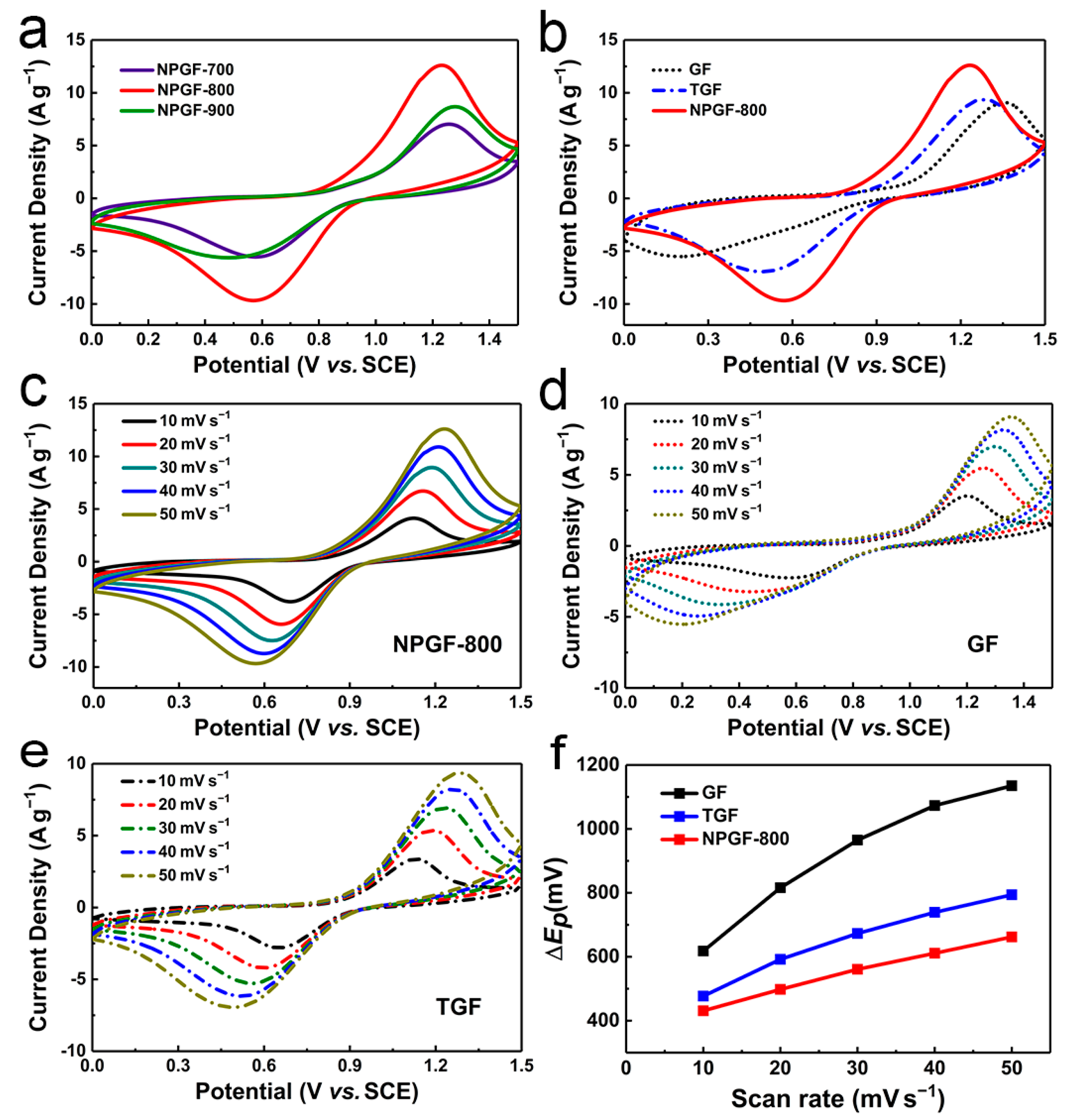
3.2. Electrochemical Performance of NPGF

The electrochemical activity of GFs for VO2+/VO2+ was characterized by CV using a three-electrode system at an electrolyte of 0.1 M VOSO4 and 3M H2SO4. As shown in Figure 3a, the annealing temperature presented a significant effect on the electrocatalytic activity of NPGF. NPGF-800 exhibited the highest electrocatalytic activity as its smallest peak difference and the highest peak current density, which could be attributed to higher total nitrogen and phosphorus content, rendering abundant oxygen-containing groups to facilitate the VO2+/VO2+ reaction. As shown in Figure 3b, compared with GF (Ipa = 9.08 A g−1, Ipc = −5.51 A g−1, −Ipc/Ipa = 0.61, ∆Ep = 1135 mV) and TGF (Ipa = 9.34 A g−1, Ipc = −6.94 A g−1, −Ipc/Ipa = 0.71, ∆Ep = 794 mV), NPGF-800 showed a higher peak current density, a smaller peak difference, and a redox peak current ratio closer to 1 (Ipa = 12.61 A g−1, Ipc = −9.68 A g−1, −Ipc/Ipa = 0.74, ∆Ep = 662 mV). Figure 3c–e shows the CV curves of VO2+/VO2+ for NPGF-800, GF, and TGF at different scan rates. Their peak potential differences at different scanning rates are presented in Figure 3f, where NPGF exhibits the smallest peak potential difference at all scan rates. These results revealed that NPGF possessed excellent electrocatalytic activity towards VO2+/VO2+ reaction.

3.3. Redox Flow Battery Performance

The outstanding electrocatalytic activity of NPGF resulted in better VRFB performance. The performance of batteries with a different positive electrode is shown in Figure 4. Figure 4a shows the charge/discharge curves of RFBs using three graphite felt samples. At the current density of 50 mA cm−2, the VRFB with NPGF showed a slightly higher discharge specific capacity (16.1 Ah L−1) than TGF (15.7 Ah L−1), achieving 80.1% of the theoretical capacity (20.1 Ah L−1). Moreover NPGF and TGF were higher than GF (13.9 Ah L−1). The discharge plates of VRFB using NPGF and TGF were also close, and both were higher than GF. However, the VRFB with NPGF demonstrated a significant rate performance at higher current densities. As shown in Figure 4b, at high current densities of 150 to 300 mA cm−2, the VRFB assembled with NPGF achieved the highest voltage efficiency compared with pristine GF and TGF. At the current density of 300 mA cm−2, the voltage efficiency of VRFB using NPGF was 75%, which was higher than that of GF (64%) and TGF (73%). This indicated that the VRFB with NPGF had better performance at high current densities. Moreover, when the current density was restored to 50 mA cm−2, the VE of the VRFB using NPGF was consistent with the initial value, while the VE of the VRFB using the other two electrodes decreased slightly, indicating that the RFB using NPGF had better rate performance. Figure 4c exhibits the charge/discharge curves of the VRFB with NPGF-800 at different current densities ranging from 50 to 300 mA cm−2. With the increase in current density, the charging platform gradually increased, the discharge platform gradually decreased, and the specific capacity gradually decreased. At the current density of 300 mA cm−2, the specific capacity remained at 9.6 Ah L−1, which corresponded to 48% of the theoretical capacity. Besides, the cycle stability of the VRFB using the NPGF electrode is presented in Figure 4d. During 100 charge/discharge cycles, whereas the coulombic efficiency slowly increased from 96% to 98%, the energy efficiency and voltage efficiency remained at 84% and 86% at the current density of 150 mA cm−2. The stability test was 59.44 h duration. The capacity of the battery remained at 80% after 100 cycles, and the decay of the capacity was mainly due to vanadium ions’ crossover membrane.
In order to comprehensively compare the performance of NPGF-800 used in VRFB, Table 2 lists the parameters and output performance of VRFB reported in recent years. The output performance of VRFB with NPGF-800 stood out from the recently reported VRFBs.

4. Conclusions

In summary, a nitrogen, phosphorus co-doped graphite felt was prepared by a simple one-step method successfully. There were abundant defects in the carbon lattice after N and P were doped. The XPS results demonstrated the successful doping of both N and P and the increase in the concentration of oxygen-containing functional groups. Compared with GF and TGF, NPGF-800 showed higher electrocatalytic activity on vanadium redox reaction, and the battery assembled with the NPGF electrode exhibited a higher voltage efficiency. At a high current of 300 mA cm−2, the voltage efficiency of VRFB assembled with NPGF as a positive electrode was 75%, which was 2% higher than that of TGF and 11% higher than that of pristine GF. Besides, the NPGF battery showed favorable stability. During 100 charge/discharge cycles, the energy efficiency and voltage efficiency remained at 84% and 86% at a current density of 150 mA cm−2.

Author Contributions

Conceptualization, L.S. and X.Y.; data curation, Z.J., L.Y. and L.S.; formal analysis, Z.J., L.Y. and L.S.; funding acquisition, L.Y., L.S. and X.Y.; methodology, Z.J., L.Y. and L.S.; project administration, L.Y., L.S. and X.Y.; supervision, L.Y., L.S. and X.Y.; validation, Z.J., L.Y. and L.S.; writing—original draft, Z.J.; writing—review and editing, L.Y. All authors will be informed about each step of the manuscript processing, including submission, revision, revision reminder, and so on, via emails from our system or assigned assistant editor. All authors have read and agreed to the published version of the manuscript.

Funding

This research was financially supported by the National Natural Science Foundation of China (No. 22209005).

Data Availability Statement

The data presented in this study are available on request from the corresponding authors.

Conflicts of Interest

The authors declare no conflict of interest.

References

  1. Dunn, B.; Kamath, H.; Tarascon, J.M. Electrical Energy Storage for the Grid: A Battery of Choices. Science 2011, 334, 928–935. [Google Scholar] [CrossRef] [PubMed] [Green Version]
  2. Sun, C.; Zhang, H. Review of the Development of First-Generation Redox Flow Batteries: Iron-Chromium System. ChemSusChem 2022, 15, e202101798. [Google Scholar] [CrossRef] [PubMed]
  3. Weber, A.Z.; Mench, M.M.; Meyers, J.P.; Ross, P.N.; Gostick, J.T.; Liu, Q. Redox flow batteries: A review. J. Appl. Electrochem. 2011, 41, 1137–1164. [Google Scholar] [CrossRef] [Green Version]
  4. Perry, M.L.; Weber, A.Z. Advanced Redox-Flow Batteries: A Perspective. J. Electrochem. Soc. 2015, 163, A5064–A5067. [Google Scholar] [CrossRef]
  5. Lourenssen, K.; Williams, J.; Ahmadpour, F.; Clemmer, R.; Tasnim, S. Vanadium redox flow batteries: A comprehensive review. J. Energy Storage 2019, 25, 100844. [Google Scholar] [CrossRef]
  6. Kim, K.J.; Park, M.-S.; Kim, Y.-J.; Kim, J.H.; Dou, S.X.; Skyllas-Kazacos, M. A technology review of electrodes and reaction mechanisms in vanadium redox flow batteries. J. Mater. Chem. A 2015, 3, 16913–16933. [Google Scholar] [CrossRef]
  7. Loskutov, A.; Kurkin, A.; Kuzmin, I.; Lipuzhin, I. Ways to Ensure Parallel Operation of Vanadium Flow Batteries to Create High Power Energy Storage Systems. Batteries 2022, 8, 120. [Google Scholar] [CrossRef]
  8. Puleston, T.; Clemente, A.; Costa-Castelló, R.; Serra, M. Modelling and Estimation of Vanadium Redox Flow Batteries: A Review. Batteries 2022, 8, 121. [Google Scholar] [CrossRef]
  9. Noack, J.; Wietschel, L.; Roznyatovskaya, N.; Pinkwart, K.; Tübke, J. Techno-Economic Modeling and Analysis of Redox Flow Battery Systems. Energies 2016, 9, 627. [Google Scholar] [CrossRef]
  10. Xing, F.; Liu, T.; Yin, Y.; Bi, R.; Zhang, Q.; Yin, L.; Li, X. Highly Active Hollow Porous Carbon Spheres@Graphite Felt Composite Electrode for High Power Density Vanadium Flow Batteries. Adv. Funct. Mater. 2022, 32, 2111267. [Google Scholar] [CrossRef]
  11. Zhang, W.; Xi, J.; Li, Z.; Zhou, H.; Liu, L.; Wu, Z.; Qiu, X. Electrochemical activation of graphite felt electrode for VO2+/VO2+ redox couple application. Electrochim. Acta 2013, 89, 429–435. [Google Scholar] [CrossRef]
  12. Greco, K.V.; Forner-Cuenca, A.; Mularczyk, A.; Eller, J.; Brushett, F.R. Elucidating the Nuanced Effects of Thermal Pretreatment on Carbon Paper Electrodes for Vanadium Redox Flow Batteries. ACS Appl. Mater. Interfaces 2018, 10, 44430–44442. [Google Scholar] [CrossRef] [PubMed]
  13. Zhang, Z.; Xi, J.; Zhou, H.; Qiu, X. KOH etched graphite felt with improved wettability and activity for vanadium flow batteries. Electrochim. Acta 2016, 218, 15–23. [Google Scholar] [CrossRef]
  14. Jiang, H.R.; Shyy, W.; Wu, M.C.; Zhang, R.H.; Zhao, T.S. A bi-porous graphite felt electrode with enhanced surface area and catalytic activity for vanadium redox flow batteries. Appl. Energy 2019, 233–234, 105–113. [Google Scholar] [CrossRef]
  15. Wu, Q.; Zhang, X.; Lv, Y.; Lin, L.; Liu, Y.; Zhou, X. Bio-inspired multiscale-pore-network structured carbon felt with enhanced mass transfer and activity for vanadium redox flow batteries. J. Mater. Chem. A 2018, 6, 20347–20355. [Google Scholar] [CrossRef]
  16. Liu, T.; Li, X.; Xu, C.; Zhang, H. Activated Carbon Fiber Paper Based Electrodes with High Electrocatalytic Activity for Vanadium Flow Batteries with Improved Power Density. ACS Appl. Mater. Interfaces 2017, 9, 4626–4633. [Google Scholar] [CrossRef]
  17. Bayeh, A.W.; Kabtamu, D.M.; Chang, Y.-C.; Chen, G.-C.; Chen, H.-Y.; Lin, G.-Y.; Liu, T.-R.; Wondimu, T.H.; Wang, K.-C.; Wang, C.-H. Ta2O5-Nanoparticle-Modified Graphite Felt as a High-Performance Electrode for a Vanadium Redox Flow Battery. ACS Sustain. Chem. Eng. 2018, 6, 3019–3028. [Google Scholar] [CrossRef]
  18. Xiang, Y.; Daoud, W.A. Binary NiCoO2-modified graphite felt as an advanced positive electrode for vanadium redox flow batteries. J. Mater. Chem. A 2019, 7, 5589–5600. [Google Scholar] [CrossRef]
  19. Ejigu, A.; Edwards, M.; Walsh, D.A. Synergistic Catalyst–Support Interactions in a Graphene–Mn3O4 Electrocatalyst for Vanadium Redox Flow Batteries. ACS Catal. 2015, 5, 7122–7130. [Google Scholar] [CrossRef] [Green Version]
  20. Zhou, H.; Xi, J.; Li, Z.; Zhang, Z.; Yu, L.; Liu, L.; Qiu, X.; Chen, L. CeO2 decorated graphite felt as a high-performance electrode for vanadium redox flow batteries. RSC Adv. 2014, 4, 61912–61918. [Google Scholar] [CrossRef]
  21. Bayeh, A.W.; Kabtamu, D.M.; Chang, Y.-C.; Chen, G.-C.; Chen, H.-Y.; Liu, T.-R.; Wondimu, T.H.; Wang, K.-C.; Wang, C.-H. Hydrogen-Treated Defect-Rich W18O49 Nanowire-Modified Graphite Felt as High-Performance Electrode for Vanadium Redox Flow Battery. ACS Appl. Energy Mater. 2019, 2, 2541–2551. [Google Scholar] [CrossRef]
  22. Han, P.; Wang, H.; Liu, Z.; Chen, X.; Ma, W.; Yao, J.; Zhu, Y.; Cui, G. Graphene oxide nanoplatelets as excellent electrochemical active materials for VO2+/VO2+ and V2+/V3+ redox couples for a vanadium redox flow battery. Carbon 2011, 49, 693–700. [Google Scholar] [CrossRef]
  23. Daugherty, M.C.; Gu, S.; Aaron, D.S.; Kelly, R.E.; Ashraf Gandomi, Y.; Hsieh, C.T. Graphene quantum dot-decorated carbon electrodes for energy storage in vanadium redox flow batteries. Nanoscale 2020, 12, 7834–7842. [Google Scholar] [CrossRef] [PubMed]
  24. Jiang, F.; He, Z.; Guo, D.; Zhou, X. Carbon aerogel modified graphite felt as advanced electrodes for vanadium redox flow batteries. J. Power Sources 2019, 440, 227114. [Google Scholar] [CrossRef]
  25. Duan, J.; Chen, S.; Jaroniec, M.; Qiao, S.Z. Heteroatom-Doped Graphene-Based Materials for Energy-Relevant Electrocatalytic Processes. ACS Catal. 2015, 5, 5207–5234. [Google Scholar] [CrossRef]
  26. Jiao, Y.; Zheng, Y.; Davey, K.; Qiao, S.-Z. Activity origin and catalyst design principles for electrocatalytic hydrogen evolution on heteroatom-doped graphene. Nat. Energy 2016, 1, 16130. [Google Scholar] [CrossRef]
  27. Paraknowitsch, J.P.; Thomas, A. Doping carbons beyond nitrogen: An overview of advanced heteroatom doped carbons with boron, sulphur and phosphorus for energy applications. Energy Environ. Sci. 2013, 6, 2839–2855. [Google Scholar] [CrossRef] [Green Version]
  28. Park, M.; Ryu, J.; Kim, Y.; Cho, J. Corn protein-derived nitrogen-doped carbon materials with oxygen-rich functional groups: A highly efficient electrocatalyst for all-vanadium redox flow batteries. Energy Environ. Sci. 2014, 7, 3727–3735. [Google Scholar] [CrossRef]
  29. He, Z.; Jiang, Y.; Wei, Y.; Zhao, C.; Jiang, F.; Li, L.; Zhou, H.; Meng, W.; Wang, L.; Dai, L. N,P co-doped carbon microsphere as superior electrocatalyst for VO2+/VO2+ redox reaction. Electrochim. Acta 2018, 259, 122–130. [Google Scholar] [CrossRef]
  30. Xu, A.; Shi, L.; Zeng, L.; Zhao, T.S. First-principle investigations of nitrogen-, boron-, phosphorus-doped graphite electrodes for vanadium redox flow batteries. Electrochim. Acta 2019, 300, 389–395. [Google Scholar] [CrossRef]
  31. Lee, H.J.; Kim, H. Graphite Felt Coated with Dopamine-Derived Nitrogen-Doped Carbon as a Positive Electrode for a Vanadium Redox Flow Battery. J. Electrochem. Soc. 2015, 162, A1675–A1681. [Google Scholar] [CrossRef]
  32. Zhang, K.; Yan, C.; Tang, A. Interfacial co-polymerization derived nitrogen-doped carbon enables high-performance carbon felt for vanadium flow batteries. J. Mater. Chem. A 2021, 9, 17300–17310. [Google Scholar] [CrossRef]
  33. Li, Y.; Yang, S.; Zhao, Y.; Mubarak, N.; Xu, M.; Ihsan-Ul-Haq, M.; Zhao, T.; Chen, Q.; Kim, J.-K. Deciphering the exceptional kinetics of hierarchical nitrogen-doped carbon electrodes for high-performance vanadium redox flow batteries. J. Mater. Chem. A 2022, 10, 5605–5613. [Google Scholar] [CrossRef]
  34. Park, S.; Kim, H. Fabrication of nitrogen-doped graphite felts as positive electrodes using polypyrrole as a coating agent in vanadium redox flow batteries. J. Mater. Chem. A 2015, 3, 12276–12283. [Google Scholar] [CrossRef]
  35. Liu, Y.; Yu, L.; Liu, X.; Liu, L.; Xi, J. ZIF-derived holey electrode with enhanced mass transfer and N-rich catalytic sites for high-power and long-life vanadium flow batteries. J. Energy Chem. 2022, 72, 545–553. [Google Scholar] [CrossRef]
  36. Wang, R.; Li, Y.; Wang, Y.; Fang, Z. Phosphorus-doped graphite felt allowing stabilized electrochemical interface and hierarchical pore structure for redox flow battery. Appl. Energy 2020, 261, 114369. [Google Scholar] [CrossRef]
  37. Wu, X.W.; Deng, Q.; Peng, C.; Zeng, X.X.; Wu, A.J.; Zhou, C.J.; Ma, Q.; Yin, Y.X.; Lu, X.Y.; Guo, Y.G. Unveiling the Role of Heteroatom Gradient-Distributed Carbon Fibers for Vanadium Redox Flow Batteries with Long Service Life. ACS Appl. Mater. Interfaces 2019, 11, 11451–11458. [Google Scholar] [CrossRef]
  38. Bi, Z.; Huo, L.; Kong, Q.; Li, F.; Chen, J.; Ahmad, A.; Wei, X.; Xie, L.; Chen, C.M. Structural Evolution of Phosphorus Species on Graphene with a Stabilized Electrochemical Interface. ACS Appl. Mater. Interfaces 2019, 11, 11421–11430. [Google Scholar] [CrossRef]
  39. Zheng, Y.; Jiao, Y.; Ge, L.; Jaroniec, M.; Qiao, S.Z. Two-step boron and nitrogen doping in graphene for enhanced synergistic catalysis. Angew. Chem. Int. Ed. Engl. 2013, 52, 3110–3116. [Google Scholar] [CrossRef]
  40. Zhang, J.; Qu, L.; Shi, G.; Liu, J.; Chen, J.; Dai, L. N,P-Codoped Carbon Networks as Efficient Metal-free Bifunctional Catalysts for Oxygen Reduction and Hydrogen Evolution Reactions. Angew. Chem. Int. Ed. Engl. 2016, 55, 2230–2234. [Google Scholar] [CrossRef]
  41. Zhang, J.; Zhao, Z.; Xia, Z.; Dai, L. A metal-free bifunctional electrocatalyst for oxygen reduction and oxygen evolution reactions. Nat. Nanotechnol. 2015, 10, 444–452. [Google Scholar] [CrossRef] [PubMed]
  42. Pasala, V.; Ramavath, J.N.; He, C.; Ramani, V.K.; Ramanujam, K. N- and P-co-doped Graphite Felt Electrode for Improving Positive Electrode Chemistry of the Vanadium Redox Flow Battery. ChemistrySelect 2018, 3, 8678–8687. [Google Scholar] [CrossRef]
  43. Park, S.E.; Lee, K.; Suharto, Y.; Kim, K.J. Enhanced electrocatalytic performance of nitrogen- and phosphorous-functionalized carbon felt electrode for VO2+/VO2+ redox reaction. Int. J. Energy Res. 2020, 45, 1806–1817. [Google Scholar] [CrossRef]
  44. Ferrari, A.C.; Robertson, J. Interpretation of Raman spectra of disordered and amorphous carbon. Phys. Rev. B 2000, 61, 14095–14107. [Google Scholar] [CrossRef] [Green Version]
  45. Bi, H.; He, X.; Zhang, H.; Li, H.; Xiao, N.; Qiu, J. N, P co-doped hierarchical porous carbon from rapeseed cake with enhanced supercapacitance. Renew. Energy 2021, 170, 188–196. [Google Scholar] [CrossRef]
  46. Yu, L.; Lin, F.; Xu, L.; Xi, J. P-doped electrode for vanadium flow battery with high-rate capability and all-climate adaptability. J. Energy Chem. 2019, 35, 55–59. [Google Scholar] [CrossRef] [Green Version]
  47. Park, S.E.; Yang, S.Y.; Kim, K.J. Boron-functionalized carbon felt electrode for enhancing the electrochemical performance of vanadium redox flow batteries. Appl. Surf. Sci. 2021, 546, 148941. [Google Scholar] [CrossRef]
  48. Zhang, K.; Yan, C.; Tang, A. Oxygen-induced electrode activation and modulation essence towards enhanced anode redox chemistry for vanadium flow batteries. Energy Storage Mater. 2021, 34, 301–310. [Google Scholar] [CrossRef]
  49. Kim, H.; Yi, J.S.; Lee, D. Marked Electrocatalytic Effects of Two-Step Boron and Oxygen Atomic Doping of Carbon Electrodes for Vanadium Redox Flow Battery. ACS Appl. Energy Mater. 2020, 4, 425–433. [Google Scholar] [CrossRef]
  50. Wang, R.; Li, Y.; Liu, H.; He, Y.-L.; Hao, M. Sandwich-like multi-scale hierarchical porous carbon with a highly hydroxylated surface for flow batteries. J. Mater. Chem. A 2021, 9, 2345–2356. [Google Scholar] [CrossRef]
Scheme 1. Fabrication of EDTMPA-modified thermally treated graphite felt and nitrogen, phosphorus co-doped graphite felt.
Batteries 09 00040 sch001
Figure 1. SEM image of (a) TGF/EDTMPA and (b) NPGF. (cf) Corresponding C, N, O, and P elemental mapping image of NPGF.
Batteries 09 00040 g001
Figure 2. Characterization of the microstructure and element composition of the electrode materials. (a) Raman spectroscopy of TGF and NPGF electrode materials. (b) Xray photoelectron spectroscopy survey spectra of TGF and NPGF-800 samples; (c,d) high resolution of N 1s and P 2p spectra of NPGF prepared by a different annealing temperature.
Batteries 09 00040 g002
Figure 3. Electrochemical properties of GF, TGF, and NPGF. (a) Cyclic voltammograms of NPGF-700, NPGF-800, and NPGF-900, the scan rate is 50 mV s−1. (b) Cyclic voltammograms of GF, TGF, and NPGF-800, the scan rate is 50 mV s−1. (ce) Cyclic voltammograms of NPGF-800, GF, and TGF, the scan rates range from 10 to 50 mV s−1. (f) The relationship between the peak potential difference and the scan rate from (ce).
Batteries 09 00040 g003
Figure 4. (a) Charge/discharge curves of batteries with GF, TGF, and NPGF-800 electrodes at a current density of 50 mA cm−2. (b) Voltage efficiency of VRFBs with GF, TGF, and NPGF-800 electrodes at current densities ranging from 50 to 300 mA cm−2. (c) Charge–discharge curves of VRFB with NPGF-800 as a positive electrode at a current density of 50 to 300 mA cm−2. (d) Capacity, coulombic efficiency, energy efficiency, and voltage efficiency of NPGF-800 batteries during the cycling test.
Batteries 09 00040 g004
Table 1. Element concentration of TGF, NPGF-700, NPGF-800, and NPGF-900.
Carbon MaterialC (at.%)N (at.%)P (at.%)N and P (at.%)O (at.%)
TGF89.071.19-1.199.74
NPGF-70088.022.391.533.928.07
NPGF-80085.542.291.844.1310.32
NPGF-90090.101.550.912.467.44
Table 2. Parameters and output performance of VRFB reported in recent years.
ElectrodesMembraneMax J
(mA cm−2)
CE
(%)
VE
(%)
EE
(%)
J
(mA cm−2)
Ref.
NPGF-800Nafion®212300968682150This work
NPGF-800Nafion®212968279200
NPGF-800Nafion®212977775250
NPGF-800Nafion®212977372300
PGF aNafion®212400968279150[46]
B-CF bNafion®117100958581100[47]
OA-CF cPSAM j300--73300[48]
N-PGF dNafion®212300--72300[35]
PEI-DA-CF ePSAM j300--74300[32]
B/O-GF fNafion®11717097898650[49]
SPHC gNafion®212300997978200[50]
GF-NP hNafion®11710094807570[42]
NPCF iNafion®212100948479100[43]
a Phosphorus-doped graphite felt, b boron-functionalized carbon felt, c ozone-accelerated acid-treated carbon felts, d nitrogen-doped porous graphite felt, e interfacial copolymerization-derived nitrogen-doped carbon, f B/O-doped graphite felt, g sandwich-like multiscale hierarchical porous carbon, h N- and P-co-doped catalyst-coated graphite felt, i N, P co-doped carbon felt, j perfluorinated sulfonic acid membrane.
Disclaimer/Publisher’s Note: The statements, opinions and data contained in all publications are solely those of the individual author(s) and contributor(s) and not of MDPI and/or the editor(s). MDPI and/or the editor(s) disclaim responsibility for any injury to people or property resulting from any ideas, methods, instructions or products referred to in the content.

