Article

Experimental Study on Atomization Characteristics of Swirl Nozzle under Annular Airflow Impingement

1
School of Mechanical Engineering and Rail Transit, Changzhou University, Changzhou 213164, China
2
Jiangsu Key Laboratory of Green Process Equipment, Changzhou University, Changzhou 213164, China
3
Jiangsu Province Engineering Research Center of High-Level Energy and Power Equipment, Changzhou University, Changzhou 213164, China
*
Author to whom correspondence should be addressed.
Fluids 2024, 9(3), 80; https://doi.org/10.3390/fluids9030080
Submission received: 9 February 2024 / Revised: 17 March 2024 / Accepted: 19 March 2024 / Published: 21 March 2024

Abstract

:
Pressure nozzles are widely used in spray drying and other industries. In order to improve the atomization characteristics of pressure cyclone nozzles, a new type of annular jet gas impingement atomization device is developed. We use high-speed imaging and digital image processing and other methods to analyze the spray characteristics of the different annular device configurations (using four, six, and eight tubes) and under different gas–liquid mass flow rates. It is shown that with an increase in the Air–Liquid mass Ratio (ALR), the liquid film breakup process changes from undulating sheet breakup to perforated sheet breakup and the breakup length decreases. The breakup length decreases the most under the condition of six-tube airflow with the range of 31–55%, while the Sauter mean diameter (SMD) basically does not change. With the increase in ALR and the Weber number of liquid (Wel), the droplet size distribution becomes more uniform. The spray characteristics of the atomizer assisted by gas jets reaches the best state when Wel = 4596.3 and m ˙ g = 1.97 g/s. The experimental conclusions have some guiding significance for the design and optimization of the atomization devices in spray drying towers.

1. Introduction

The issue of exhaust pollution from coal-fired boilers is increasingly severe [1,2], garnering growing attention towards flue gas deacidification technology. Spray drying technology is a representative semi-dry deacidification method. Through the reaction between atomized droplets and high-temperature gas, the droplets evaporate to obtain dry products. Hence, the uniformity of the gas–liquid mixture and the duration of atomization play an important role in process of deacidification [3]. Understanding spray characteristics under different conditions such as breakup length, spray angle, Sauter mean diameter (SMD), and droplet particle size distribution is vital for achieving thorough mixing and enhancing atomization performance in spray drying towers.
Common atomizers can be classified into two categories: single-fluid and dual-fluid types. Single-fluid atomizers can be further divided into rotational (centrifugal), air-induced, and pressure-induced types [4,5,6]. Pressure swirl atomizers have a simple structure and are an ideal choice for spray drying systems. Muhammad et al. [7] studied the influence of the geometric parameters of pressure atomizers on spray cone angle and SMD and determined the optimal parameters. Xue et al. [8] conducted experimental research on the influence of four geometric parameters on atomizer performance. They found that increasing the ingress groove angle led to a decrease in film thickness and discharge coefficient, and an increase in spray cone angle, while the convergence angle of the swirl chamber had the opposite effect on performance parameters. Amini et al. [9] found that the spray angle, discharge coefficient, and hollow core radius are inversely proportional to the length of the atomizer. Among various geometric parameters of pressure swirl nozzles, the aperture size has the most significant impact on atomization characteristics. Liu et al. [10] studied pressure swirl atomizers with different structures using a combined experimental and simulation method. They found that geometric differences significantly affected the atomization characteristics such as spray angle and SMD. In addition, Durdina et al. [11] explored the spray characteristics generated by pressure swirl injectors using Phase Doppler Particle Analyzer (PDPA) and Particle Image Velocimetry (PIV). As the pressure increased, the maximum mass flow rate and local velocity around the spray dominated, resulting in a full-cone spray. Jain et al. [12] found, based on the inviscid theory, that the spray cone angle and SMD decreased with the increase in the Reynolds number.
To improve the atomization performance of pressure swirl nozzles, scholars have carried out a lot of research on optimizing the nozzle structure and improving the atomization parameters. Gas jet-assisted atomization has proved to be an effective strategy. Kalpana et al. [13] used the numerical simulation method to study aluminum liquid pipes and annular gas jet ejectors. They showed that with the increase in gas pressure, the droplet size distribution became more uniform. Patel et al. [14] designed a new electrostatic spraying system to improve the spraying efficiency by installing an annular air auxiliary device outside the electrostatic ejector. Based on the above research, a new type of annular gas jet impingement atomization device with a pressure swirl atomizer is designed in this paper, and its atomization characteristics are experimentally studied by constructing an experimental device. Using high-speed imaging and a digital image processing method, we studied the breakup length, spray angle, SMD, and droplet size distribution under different annular airflow, different liquid mass flow, and air mass flow. Based on the experimental data, the atomization performance of atomizer under the impact of gas jet was studied by using a multiparameter system.

2. Materials and Methods

2.1. Gas Jet Impact Atomizer

As shown in Figure 1, the gas jet impact atomization device consisted of two parts: a ring-shaped gas jet device and a pressure swirl atomizer. The orifice diameter of the pressure swirl atomizer was 1.5 mm, and its atomization process is shown in Figure 2. Annular gas pipelines with 4, 6, and 8 pipes were selected as the gas jet devices. The annular tube diameter was 100 mm with a needle length of 70 mm and gas orifice diameter of 2 mm. The inclination angle was 30° (Figure 1).

2.2. Experimental Setup

Figure 3 illustrates the schematic diagram of the experimental setup for swirl injector atomization under annular gas flow. It consists of a water supply system, gas supply system, atomization system, and measurement system. In the water supply system, the medium in the storage tank is divided into two separate flow channels: the main channel directly flows to the pressure injector, and the other channel acts as a regulating pipeline returning to the storage tank and finally sprayed out by the injector. The inner diameter of the pipes in the water supply system was 6 mm, which is four times the size of the pressure injector hole, ensuring that the pressure drop in the supply system could be neglected. The pressure in the main channel was precisely regulated using a control valve. The flow rate and pressure of the water were accurately measured and monitored using an electronic gear flow meter with an accuracy of ±0.1% and a pressure gauge with a measurement range of 0 to 2.5 MPa. In the gas supply system, the gas source was provided by an air compressor. The gas volume flow rate was measured using the LZM-15zt panel-type flowmeter (Nanjing Kelihua Instument and Meter Co., Ltd., Nanjing, China), with a range of 0.8 to 8 m3/h and an accuracy of ±4%. The experiments were conducted at 20 °C, using water and air as the working media (the physical properties of water: density, ρ l = 997 kg/m3, viscosity, μ l = 1.00 × 10⁻³ Pa·s, and surface tension, σ = 7.28 × 10⁻² N/m [15]).

2.3. Imaging System

The imaging system consists of an LED light source, power controller, high-speed camera, and PC. The power controller supplies power to the system, the high-speed camera is connected to the computer to ensure stable shooting and real-time saving of the images, and the LED light source provides stable illumination. The LED light source was provided by a NanGuang CN-T200ll unit (Guangdong Nanguang Film and Television Equipment Co., Ltd., Cantou, China), with a power output of 40 W, color temperature of 5600 K, and brightness of 3344 lm. The high-speed camera (Speedsense VEO-640, Dantec Dynamics A/S, Copenhagen, Denmark) was used to visualize the atomization process with a maximum resolution of 2560 × 1600, recording rate of 500 fps (frames per second), and an exposure time of 5 μs. The spray images were captured using a 100 mm macro lens (Tokina F2.8, Dantec Dynamics A/S, Copenhagen, Denmark). The minimum measurable droplet diameter range was about 20 μm because of the camera resolution limit. θ, Lb, SMD, and droplet size distribution were obtained by image processing.
The entire process is as follows: Firstly, the high-speed camera was positioned at the same height as the injector and vertically aligned with the spray axis. Both the high-speed camera and LED light source can be vertically adjusted to ensure alignment and focus. The magnification was determined based on the observation range and the clarity requirement for the liquid film. Spray morphology images were captured after the airflow stabilizes. The camera height was adjusted to capture the droplet images. The test area was located 40 mm below the injector outlet.

2.4. Image Preprocessing

As shown in the figure, the captured liquid film and droplet images are preprocessed separately using MATLAB (Ver. R2018a) code. Taking droplet preprocessing as an example, the entire process includes illumination correction, image enhancement, noise removal, binarization, elimination of incomplete droplets, and elimination of defocused droplets, and can be summarized as below.
The process is as follows: Firstly, to correct the non-uniform illumination, the bottom-hat transform [16] was applied. The image after illumination correction was not high enough in contrast ratio (Figure 4b) and it was difficult for droplets to be recognized and extracted. Gray-level transformation [17] was applied to enhance the contrast ratio (Figure 4c). Denoising using the median filter [18] was required, considering that a number of micro noise points could be misidentified as droplets (Figure 4d). To maintain the morphological information of the gray-level image for object recognition and parameters extraction, binarization was applied. The binary image after OTSU [19] binarization is shown in Figure 4e. Defocused droplets were effectively removed through the calculation of the gray gradient of the original image and the setting of an appropriate threshold. The bwlabel function was applied to each droplet region to perform individual labeling. After the labeling was completed, a pseudo-colored indexed image was used to display the labeled image, facilitating the observation, statistical analysis, and extraction of droplet information. This process was accomplished by employing the label2rgb function (Figure 4f). After image binarization and other processing, in the binarized image, the droplet shape was approximately circular, the single-droplet contour was detected based on Hough transform, and the circular radius and other information were extracted. This process was realized by the imfindcircles function.
The image processing of liquid film is similar to that of liquid droplets, which is not repeated here (Figure 5). After completing the preprocessing of the liquid film images, the least-squares method was used to fit the edge curve of the liquid film, obtaining data such as the spray angle and breakup length. The spray angle, denoted as θ (as shown in Figure 5a), is defined as the average angle at which liquid spray emanates from the nozzle tip [20]. The height at which the exited continuous liquid film of the atomizer completely disintegrates and turns into droplets is called the breakup length [21] and is indicated by the symbol Lb.

2.5. Analysis of Uncertainty

A standard distance scale was utilized to quantify the measurement in images to ensure accuracy. Particularly, with the camera settings unchanged, we captured images of the ruler in the same position and calculated the number of pixels (n) corresponding to the geometric dimension of the ruler. Using the formula p = a/n, we obtained the actual size represented by a single pixel in the image, which was determined to be 16 μm/pixel for the measurement system under our experimental conditions. The droplets were initially focused during the capturing process. After the image processing steps, the droplet diameters were obtained by using a scale factor obtained by calibration.
During the experimental process, 500 spray images were captured under stable operating conditions. Subsequently, these macroscopic spray images were processed. The final spray cone angle was determined by calculating the average of the values under each experimental condition. From the error analysis of the spray cone angle measurements, it was found that the maximum deviation from the mean value was 1.5%. Using the same method to measure the length of liquid film fragmentation, the uncertainty was about 3%.
The uncertainty of measuring the size of a single droplet is shown in Figure 6, and the droplets are approximated as circles. It can be observed that the measured diameter of the target circle occupies 10 pixels, while the droplet edges occupy 0.5 pixels. Through this measurement method, it was found that the uncertainty of the measured droplet edges is within 5%. On average, approximately 5000 droplets were considered from 100 images in each case. All other droplets were processed in the same manner to obtain their respective circle radii. The relative uncertainty of SMD is within ±6%.
Several dimensionless parameters including the Wel and the Air–Liquid mass Ratio (ALR) were defined to better represent the results [22]. The specific values are shown in Table 1.
t f = 2.77 d l m ˙ l μ l ρ l Δ ρ
b = 4 t f ( d l - t f )
v a = m ˙ ρ l π t f ( d l - t f )
W e l = ρ l v a 2 b σ
A L R = m ˙ g m ˙ l
where t f is the thickness of the liquid film, d l is the nozzle aperture, m ˙ l is the liquid flow rate, μ l is the dynamic viscosity of water, ρ l is the density of water, b is the characteristic length of the atomizer, v a is the characteristic velocity of spray, Wel is the liquid Weber number, and σ is the surface tension coefficient of water.

3. Results and Discussion

3.1. Liquid Film Breakup Morphology

The first step in analyzing spray characteristics is typically understanding the behavior of liquid film breakup. Figure 7 shows different breakup patterns of the liquid film under four, six, and eight pipes at varying Wel. The image sequences from left to right show the effects of different ALRs on the spray behavior at a constant Wel. The images depict the conical liquid sheet pattern, the unstable waves on the liquid film surface, detailed liquid film breakup, and the atomized droplets. For the pressure swirl atomizer (ALR = 0), the breakup of the conical liquid sheet occurs through the unstable growth of surface waves. As the waves propagate downward, the edges of the liquid film contract due to the mechanism of Rayleigh instability. Then, it creates curved boundaries and forms a ring-shaped cylindrical liquid ligament. Concurrently, the initial atomization occurs, and the liquid ligament begins to peel off from the liquid membrane. The liquid ligament is further broken under the action of air and decomposed into small droplets. This is the process of secondary atomization. When ALR is relatively low (ALR ≤ 0.045), the aerodynamic instability of the liquid film dominates the near-field atomization process. The impact of the gas jet on the liquid film intensifies the atomization process. As the ALR increases, the interaction between the gas and liquid phases strengthens, leading to an increase in kinetic energy transfer. Holes start to appear on the liquid film, and the edge curves undergo more noticeable contraction. The position of the first breakup of the spray shifts upstream. Intense gas–liquid interaction causes partial separation of the annular liquid ligament from the upstream liquid film, and the liquid ligament is torn apart by the airflow. When ALR > 0.099, the broken liquid block breaks into some ligaments and numerous droplets. This process can be distinctly observed under six tubes.
Taking the example of the liquid film breakup process for six tubes at Wel = 2865.9, as shown in Figure 8, it can be observed that with the increase in ALR, the liquid film breakup process shifts from a wave-like sheet breakup to perforated sheet breakup [23,24] (Figure 8d). Particularly, it can be observed that the edge of the liquid film undergoes significant contraction under the interference of the jet airflow (Figure 8b). The surface waves of the liquid film are overwhelmed, and holes are generated on the surface (Figure 8c,d red pane). The growing holes are surrounded by the loop-like cylindrical free rims propagating according to the Taylor–Culick mechanism [25], causing the liquid film to bend towards the axial position (Figure 8c). At this point, due to the pressure imbalance inside and outside the liquid film, the gas flows downstream along the outer surface of the liquid, detaching droplets from the edge of the hole (Figure 8d). As the liquid film becomes thinner and the gas disturbance continues, the hole continues to flow downstream and grow, forming ligaments and completing the final rupture. Due to high momentum transfer between the gas and liquid, the downstream liquid film is forced to break down into small droplets rather than liquid ligaments. This blurs the boundary between primary and secondary atomization and enhances gas–liquid mixing efficiency, which help improve the gas–liquid contact area and aid in the progress of spray drying. In summary, the liquid film breakup process is primarily influenced by ALR. The impacting of gas flow and gas–liquid interfacial interaction collectively promote liquid film breakup.
The disturbance status of the liquid film surface waves by the air jet can be observed and analyzed through the recognizable structures on its surface. Figure 9 illustrates the variation in wavelength (λ) of the spiral waves on the liquid film surface at different Wel. When ALR = 0 (Figure 9a,c), spiral waves appear on the surface of the conical liquid sheet. This is related to the mechanism of pressure swirl atomization. λ decreases with increasing Wel. The increase in aerodynamic momentum leads to the disappearance of spiral waves on the liquid sheet surface at low Wel (Wel = 2122.9), and the formation of holes on the liquid film surface (Figure 9b red pane). This may be attributed to the increased aerodynamic momentum. It causes the liquid film to be unable to resist the interference of the gas. When Wel is increased to 4596.3, λ increases under the interference of aerodynamic momentum. The jet airflow disrupts the liquid film surface, altering the surface waves of the liquid film.

3.2. Breakup Length

Figure 10 illustrates the variation in breakup lengths (Lb) under different numbers of tubes (four, six, and eight) and various Wels. For a fixed Wel, Lb decreases with an increase in m ˙ g . The increase in air mass flow amplifies the relative mass flow difference between the gas and liquid phases, leading to a reduction in liquid film breakup length, which is especially pronounced at relatively lower Wel values. At m ˙ g = 0, the Lb values for Wel = 2122.9, 2865.9, 3735.8, and 4596.3 are 14.8 mm, 11.7 mm, 10.2 mm, and 10 mm, respectively, showing a decrease in Lb with increasing Wel. This behavior is related to the atomization mechanism of the pressure swirl atomization device. As m ˙ g increases, the Lb for four tube bundles with Wel = 2122.9, 2865.9, 3735.8, and 4596.3 decreases by 42%, 27%, 15%, and 15%, respectively. For six tubes, the Lb decreases by 55%, 40%, 30%, and 31%, and for eight tubes, the Lb decreases by 53%, 40%, 30%, and 25%. Comparatively, 6 tubes exhibit the most effective breakup. This is because, at the same m ˙ g , the liquid film under four tubes has fewer impact points, resulting in less disturbance spots from the airflow. Eight tubes have the most impact points, but each tube has relatively lower flow rate (since we kept the whole air flow rate constant throughout the study). This results in less momentum transfer from the airflow to the liquid film, and thus less impact on the breakup of the liquid film.
It is interesting that the breakup length reaches its minimum value at m ˙ g = 1.97 g/s regardless of the number of tubes and the minimum breakup length of different Wels is very close. This could be attributed to the fixed angle of the tubes, and the point of action of the airflow on the liquid film remains relatively constant. When the air mass flow increases to a certain extent, airflow disturbance plays a dominant role in the liquid film breakup process. Taking the example of six tubes (Figure 10b), the breakup lengths under different Wel values are nearly the same at high m ˙ g ( m ˙ g ≥ 1.61 g/s). At this point, the breakup length is mainly related to the mass flow rate of the gas.
Figure 11 presents the breakup lengths under conditions of 20 different ALRs, where Lb/dl [26] is correlated with ALR through a power-law fit (y = ax−b, a, b see Figure 11). When ALR < 0.03, Lb /dl decreases significantly with increasing ALR under different tubes, this is because the increase in relative flow at the air–liquid interface leads to the increased influence of gas on liquid flow. However, when ALR > 0.03, the rate of decrease in Lb/dl becomes smaller. This is attributed to the relatively fixed angle of the tubes. When the breakup location of the liquid film moves upstream near the impact point, the disturbance time of the airflow on the liquid film shortens, reducing its influence on the breakup, and resulting in a slower decrease in breakup length with increasing ALR.

3.3. Spray Angle

The measured values of spray angles under different test conditions were obtained from their respective spray images, as shown in Figure 5a. Each data point of θ corresponds to the average of 25–35 measurements obtained from spray images captured in different test runs under a given flow condition. Figure 12a–c illustrate the relationship between spray angle and ALR for the four-, six-, and eight-tube conditions, respectively.
It can be observed that the spray angle decreases with increasing ALR. These findings are consistent with the report by Poozesh et al. [26] For a fixed Wel, under 0 < ALR < 0.015, the spray cone angle exhibits a sharp decrease with increasing airspeed. When ALR > 0.015, the cone angle stabilizes and decreases. The initial spray angle of ALR = 0 and the angle after ALR increases in different tube numbers are shown in Table 2.
As we can see, the spray angle is relatively small for four tubes. Compared with the absence of an air jet, the angles of the six and eight tubes were reduced by about 6%. Additionally, for each Wel, the spray cone angle does not infinitely decrease with increasing ALR. Therefore, the introduction of air jet leading to changes in spray angle after liquid film breakup is acceptable.

3.4. Spray Droplet Size Characteristics

3.4.1. Sauter Mean Diameter

Due to the complex spray processes beneath the nozzle, such as atomization and droplets interactions (bouncing, coalescence, and separation [27]), the measurement of spray droplet size distribution was conducted in close proximity to the nozzle for each experimental condition. The SMD is commonly employed to characterize atomization efficiency [28], representing the ratio of the volume to surface area of the entire spray [29]. This diameter is used to depict the total area available for heat and mass transfer in the atomization process:
S M D = D i 3 N i D i 2 N i
As shown in Figure 13, under different nozzles and Wels, the SMD fluctuates around near a certain value with increasing m ˙ g (see Table 3).
At m ˙ g = 0, as Wel increases, SMD decreases, but the reduction is relatively small. With a fixed Wel, as m ˙ g increases, SMD remains nearly unchanged. It can be deduced that the introduction of the gas flow has a great impact on SMD. The annular air jet impacts the liquid film, enhancing the energy of the liquid flow, thus accelerating the processes of film fragmentation and atomization. However, the contraction of the liquid film increases the possibility of droplet collisions, leading to droplet coalescence. This should be one of the reasons for the stability of SMDs when the air flow changes.
Additionally, an intriguing phenomenon was observed through a comparison of droplet images with and without airflow. The liquid film takes on a spiral deformation and breaks apart into droplets (ALR = 0). These droplets are propelled along the direction of the spiral liquid sheet, exhibiting a distinctive periodic spatial distribution in the form of transverse striped bands. When ALR > 0.1, the droplets are distributed along the airflow direction. This is attributed to the force of the airflow altering the droplet direction, causing them to move towards the axis of the spray cone. The introduction of the airflow alters the spatial distribution of the droplets, as depicted in Figure 14.

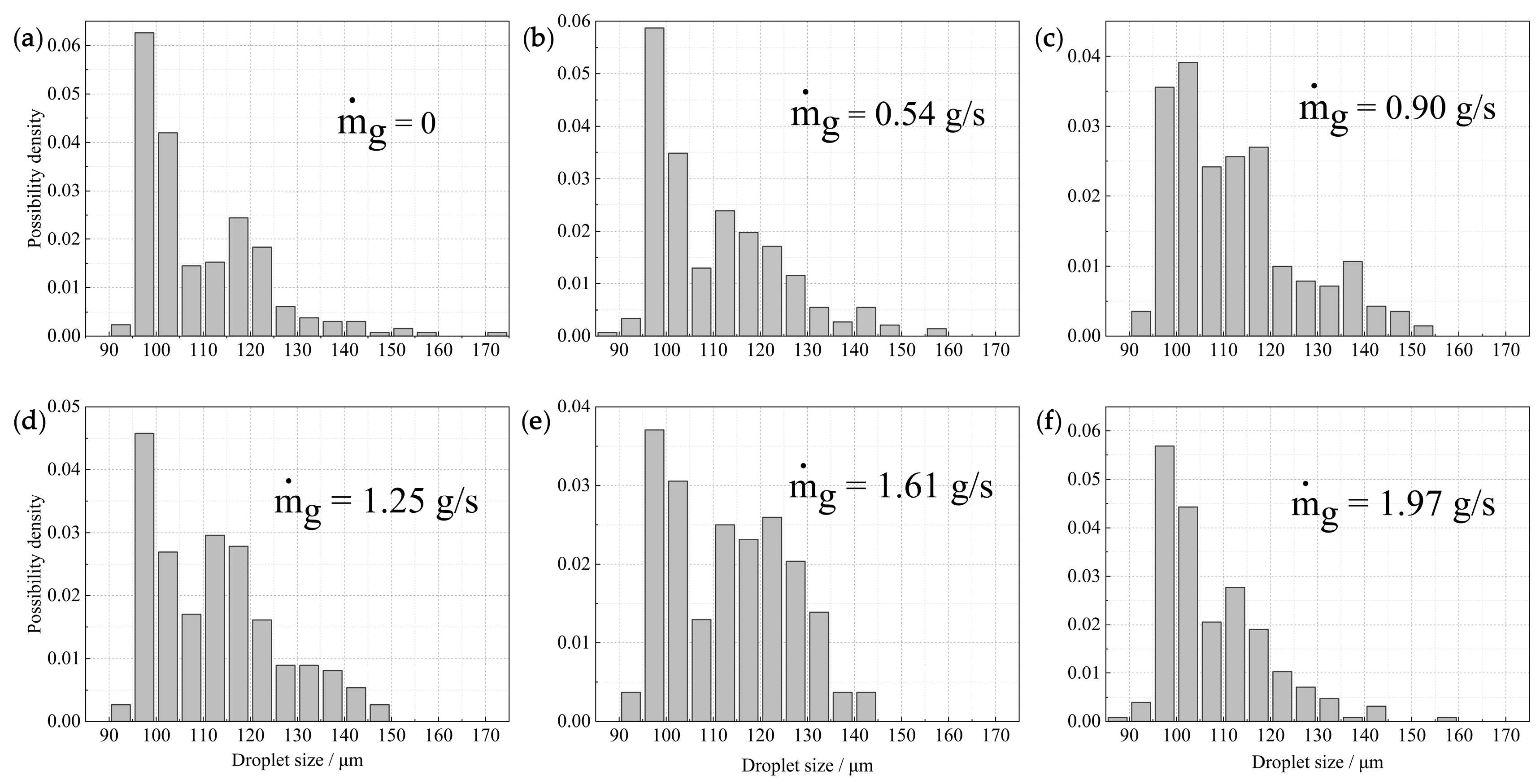
3.4.2. Droplet Size Distribution

In the process of spray drying, droplet size plays a decisive role in the evaporation time of the slurry. Larger droplets determine the overall evaporation time, and even under the same SMD conditions, the proportion of large droplets may vary. Therefore, the analysis of droplet size distribution is crucial.
For the annular gas path with six nozzles, the probability density distribution of droplet sizes under Wel = 2122.9 and different mass flow rates ( m ˙ g ) is shown in Figure 15. It can be observed that droplet size distribution is concentrated within the range of 85–160 μm. At m ˙ g = 0 (Figure 15a) and m ˙ g = 1.97 g/s (Figure 15f), the droplet size distribution ranges are 90–170 μm and 85–130 μm, respectively. An increase in m ˙ g leads to a narrower range of droplet size distribution and a reduction in the maximum droplet size. Considering the diversity in droplet sizes [30], this indicates better uniformity in droplet distribution. Similar findings were observed under other Wels. This may be attributed to the airflow enhancing the kinetic energy of the droplets, accelerating the fragmentation of large droplets, and causing the droplets to be distributed axially along the airflow direction.
Furthermore, the peaks of droplet size density distribution under different m ˙ g conditions are all located around 100 μm. This indicates that the arithmetic mean droplet size hardly changes with an increase in m ˙ g , which is consistent with the trend observed in SMD. Comparing droplet size distributions under different Wel at m ˙ g = 1.97 g/s (Figure 16), it is shown that an increase in Wel results in a more uniform droplet distribution. When Wel is increased to 4596.3, the probability density of droplets smaller than 95 μm and larger than 130 μm disappears, representing the coalescence of small droplets and the fragmentation of large droplets. Overall, at Wel = 4596.3 and m ˙ g = 1.97 g/s, the droplet size distribution is most uniform.

4. Conclusions

A new type of annular jet gas impingement atomization device is proposed. A high-speed photography technique is employed to capture the spray of different annular device configurations and different gas–liquid mass flow rates. Through the digital image processing method, image acquisition and parameter extraction are completed. The spray characteristics such as the instability structure of the liquid film, the breakup length, and the SMD are discussed comparatively for the typical working conditions. The following conclusions were drawn:
(a) Comparing and analyzing liquid film breakup process with and without airflow conditions, it was found that the liquid film breakup process changes from undulating sheet breakup to perforated sheet breakup with the increase in ALR. Furthermore, the air jet a disturbed the spiral waves on the liquid film surface, and the wavelength λ increased with the increase in m ˙ g .
(b) The breakup trends under different nozzle configurations (4, 6, 8) were the same. For the same Wel, Lb decreased with the increase in m ˙ g , and the configuration with six tubes showed the best performance. With the increase in ALR, the spray angle and Lb drops sharply at first, and then decreases slowly. The inflection point of Lb is about ALR = 0.03, and the point of θ is at ALR = 0.015. For each Wel, the spray angle does not decrease infinitely with the increase in air mass flow.
(c) When m ˙ g = 0, increasing Wel resulted in a smaller SMD, but the decrease was relatively small. Fixing Wel and increasing m ˙ g do not change the droplet SMD. The introduction of airflow does not always reduce droplet size, because the annular jet promotes liquid film fragmentation and leads to droplet aggregation. Under high gas and liquid mass flows, the probability density distribution of droplet becomes more uniform. The most uniform droplet size distribution was observed at Wel = 4596.3 and m ˙ g = 1.97 g/s.
(d) The introduction of the annular jet device improves the atomization performances and the effect of gas–liquid mixing (the configuration with six tubes shows the best performance). The research results have certain guiding significance for the design and optimization of atomization devices in spray drying towers. Due to limitations, this study did not conduct further research on the surface waves and breakup mechanisms of the liquid film, which should be further explored in future work.

Author Contributions

Conceptualization, Q.H.; methodology, Q.H.; software, Q.H. and D.Z.; validation, Q.H., X.L. and D.Z.; formal analysis, Q.H., X.L. and D.Z.; investigation, Q.H. and B.S.; resources, X.L.; data curation, Q.H. and S.S.; writing—original draft preparation, Q.H.; writing—review and editing, Q.H., X.L. and D.Z.; visualization, Q.H. and B.S.; supervision, X.H. and L.S.; project administration, X.L.; funding acquisition, X.L. All authors have read and agreed to the published version of the manuscript.

Funding

This research was funded by the technology research and development project of Zhong’an United Coal Chemical Co., Ltd. [grant number 2022K2721]. This work was also funded by the Jiangsu Provincial Key Laboratory of Green Process Equipment [grant number GPE202301] and Changzhou University Research Start-up Fund [grant number ZMF23020056].

Data Availability Statement

The data presented in this study are available on request from the corresponding author. For certain policy reasons, it is not convenient to publicize the data in this paper.

Acknowledgments

The authors would also like to thank the Jiangsu Key Laboratory of Green Process Equipment. Liu and Zhang from Changzhou University are also gratefully acknowledged.

Conflicts of Interest

The authors declare no conflicts of interest. The authors declare that the funder from Zhong’an United Coal Chemical Co., Ltd. was not involved in the study design, collection, analysis, interpretation of data, the writing of this article, or the decision to submit it for publication.

References

  1. Cui, W.; Li, J.; Xu, W.; Güneralp, B. Industrial electricity consumption and economic growth: A spatio-temporal analysis across prefecture-level cities in China from 1999 to 2014. Energy 2021, 222, 119932. [Google Scholar] [CrossRef]
  2. Han, L.; Zhou, W.; Li, W.; Qian, Y. Urbanization strategy and environmental changes: An insight with relationship between population change and fine particulate pollution. Sci. Total Environ. 2018, 642, 789–799. [Google Scholar] [CrossRef] [PubMed]
  3. Zhang, T.; Tang, Q.; Pu, C.; Zhang, L. Numerical simulation of gas-droplets mixing and spray evaporation in rotary spray desulfurization tower. Adv. Powder Technol. 2022, 33, 103420. [Google Scholar] [CrossRef]
  4. Vecellio, L.; Kippax, P.; Rouquette, S.; Diot, P. Influence of realistic airflow rate on aerosol generation by nebulizers. Int. J. Pharm. 2009, 371, 99–105. [Google Scholar] [CrossRef] [PubMed]
  5. Igari, N.; Iso, T.; Nishio, Y.; Izawa, S.; Fukunishi, Y. Numerical simulation of droplet-formation in rotary atomizer. Theor. Appl. Mech. Lett. 2019, 9, 202–205. [Google Scholar] [CrossRef]
  6. Khedkar, N.K.; Sonawane, C.; Chandras, A.; Kulkarni, A.; Sawant, R. Experimental and numerical investigation of Cross-Flow nebulizer for developing optimized suction pressure. Mater. Today Proc. 2022, 59, 617–622. [Google Scholar] [CrossRef]
  7. Rashad, M.; Yong, H.; Zekun, Z. Effect of geometric parameters on spray characteristics of pressure swirl atomizers. Int. J. Hydrogen Energy 2016, 41, 15790–15799. [Google Scholar] [CrossRef]
  8. Xue, J.; Jog, M.A.; Jeng, S.M.; Steinthorsson, E.; Benjamin, M.A. Effect of geometric parameters on simplex atomizer performance. AIAA J. 2004, 42, 2408–2415. [Google Scholar] [CrossRef]
  9. Amini, G. Liquid flow in a simplex swirl nozzle. Int. J. Multiph. Flow 2016, 79, 225–235. [Google Scholar] [CrossRef]
  10. Liu, J.; Feng, X.; Liang, H.; Zhang, W.; Hui, Y.; Xu, H.; Yang, C. Prediction of atomization characteristics of pressure swirl nozzle with different structures. Chin. J. Chem. Eng. 2023, 63, 171–184. [Google Scholar] [CrossRef]
  11. Durdina, L.; Jedelsky, J.; Jicha, M. Spray structure of a pressure-swirl atomizer for combustion applications. In Proceedings of the Conference on Experimental Fluid Mechanics (EFM), Jicin, Czech Republic, 22–25 November 2011. [Google Scholar]
  12. Jain, M.; John, B.; Iyer, K.N.; Prabhu, S.V. Characterization of the full cone pressure swirl spray nozzles for the nuclear reactor containment spray system. Nucl. Eng. Des. 2014, 273, 131–142. [Google Scholar] [CrossRef]
  13. Hanthanan Arachchilage, K.; Haghshenas, M.; Park, S.; Zhou, L.; Sohn, Y.; McWilliams, B.; Cho, K.; Kumar, R. Numerical simulation of high-pressure gas atomization of two-phase flow: Effect of gas pressure on droplet size distribution. Adv. Powder Technol. 2019, 30, 2726–2732. [Google Scholar] [CrossRef]
  14. Patel, M.K.; Sahoo, H.K.; Nayak, M.K.; Ghanshyam, C. Plausibility of variable coverage high range spraying: Experimental studies of an externally air-assisted electrostatic nozzle. Comput. Electron. Agric. 2016, 127, 641–651. [Google Scholar] [CrossRef]
  15. Lefebvre, A.; McDonell, V. Atomization and Sprays, 2nd ed.; CRC Press: Boca Raton, FL, USA, 2017. [Google Scholar]
  16. Roerdink, J.B.T.M. Group morphology. Pattern Recognit. 2000, 33, 877–895. [Google Scholar] [CrossRef]
  17. Raji, A.; Thaibaoui, A.; Petit, E.; Bunel, P.; Mimoun, G. A gray-level transformation-based method for image enhancement. Pattern Recognit. Lett. 1998, 19, 1207–1212. [Google Scholar] [CrossRef]
  18. Sun, H.; Luo, Y.; Ding, H.; Li, J.; Song, C.; Liu, X. Experimental investigation on atomization properties of impaction-pin nozzle using imaging method analysis. Exp. Therm. Fluid Sci. 2021, 122, 110322. [Google Scholar] [CrossRef]
  19. Otsu, N. Threshold Selection Method from Gray-Level Histograms. IEEE Trans. Syst. Man Cybern. 1979, 9, 62–66. [Google Scholar] [CrossRef]
  20. Leroux, B.; Delabroy, O.; Lacas, F. Experimental study of coaxial atomizers scaling. Part I: Dense core zone. At. Sprays 2007, 17, 381–407. [Google Scholar] [CrossRef]
  21. Rostami, E.; Mahdavy Moghaddam, H. Distribution function and atomization parameters of petroleum fuels sprays: An experimental and numerical study. Results Eng. 2024, 21, 101692. [Google Scholar] [CrossRef]
  22. Xia, Y.; Alshehhi, M.; Hardalupas, Y.; Khezzar, L. Spray characteristics of free air-on-water impinging jets. Int. J. Multiph. Flow 2018, 100, 86–103. [Google Scholar] [CrossRef]
  23. Sivakumar, D.; Kulkarni, V. Regimes of spray formation in gas-centered swirl coaxial atomizers. Exp. Fluids 2011, 51, 587–596. [Google Scholar] [CrossRef]
  24. Chatterjee, S.; Das, M.; Mukhopadhyay, A.; Sen, S. Experimental Investigation of Breakup of Annular Liquid Sheet in a Hybrid Atomizer. J. Propuls. Power 2015, 31, 1232–1241. [Google Scholar] [CrossRef]
  25. Bang, B.-H.; Ahn, C.-S.; Yoon, S.S.; Yarin, A.L. Breakup of swirling films issued from a pressure-swirl atomizer. Fuel 2023, 332, 125847. [Google Scholar] [CrossRef]
  26. Poozesh, S.; Grib, S.W.; Renfro, M.W.; Marsac, P.J. Near-field dynamics of high-speed spray dryer coannular two fluid nozzle: Effects of operational conditions and formulations. Powder Technol. 2018, 333, 439–448. [Google Scholar] [CrossRef]
  27. Hou, L.; Zhang, D.W.; Fan, X.J. Spatial structure and droplet distribution of atomization by three circularly arranged impinging jets. At. Sprays 2022, 32, 29–49. [Google Scholar] [CrossRef]
  28. Panão, M. Interpreting Liquid Atomization Efficiency. Int. J. Eng. Technol. Inform. 2021, 2, 121–124. [Google Scholar] [CrossRef]
  29. Kang, Z.; Wang, Z.-G.; Li, Q.; Cheng, P. Review on pressure swirl injector in liquid rocket engine. Acta Astronaut. 2018, 145, 174–198. [Google Scholar] [CrossRef]
  30. Panao, M.O.; Moita, A.S.; Moreira, A.L. On the Statistical Characterization of Sprays. Appl. Sci. 2020, 10, 6122. [Google Scholar] [CrossRef]
Figure 1. Gas jet atomization device with annular set (a) 4; (b) 6; (c) 8.
Fluids 09 00080 g001
Figure 2. Liquid film and primary and secondary breakup processes.
Fluids 09 00080 g002
Figure 3. Schematic diagram of the experimental setup for swirl injector atomization under annular gas flow.
Fluids 09 00080 g003
Figure 4. Image preprocessing: (a) original image; (b) processed image after illumination correction; (c) processed image after gray-level enhancement; (d) denoised image with median filter; (e) binary image with Otsu method; (f) color-marked droplet.
Fluids 09 00080 g004
Figure 5. Liquid film breaking length: (a) captured image; (b) morphological processing image; (c) edge detection image.
Fluids 09 00080 g005
Figure 6. The uncertainty of droplet edge measurement.
Fluids 09 00080 g006
Figure 7. Liquid film fragmentation morphology under different ALR conditions at Wel = (a) 2122.9, (b) 2865.9, and (c) 4596.3.
Fluids 09 00080 g007
Figure 8. Liquid film fragmentation process (different ALR at 6 tubes, Wel = 2865.9) at ALR = (a) 0, (b) 0.067, (c) 0.093, (d) 0.146.
Fluids 09 00080 g008
Figure 9. Liquid film surface waves at different ALR values at Wel = 2122.9 and 4596.3.
Fluids 09 00080 g009
Figure 10. Tubes of (a) 4, (b) 6, and (c) 8 m ˙ g –breakup length.
Fluids 09 00080 g010
Figure 11. Tubes of 4, 6, and 8 ALR–Lb/dl.
Fluids 09 00080 g011
Figure 12. Tubes of (a) 4, (b) 6, and (c) 8 AL-θ.
Fluids 09 00080 g012
Figure 13. Tubes of (a) 4, (b) 6, and (c) 8 m ˙ g -SMD.
Fluids 09 00080 g013
Figure 14. Spatial distribution of (a) horizontal and (b) vertical droplet images.
Fluids 09 00080 g014
Figure 15. Probability density distribution of different m ˙ g under Wel = 2122.9.
Fluids 09 00080 g015
Figure 16. Probability density distribution of different Wel under m ˙ g = 1.97 g/s.
Fluids 09 00080 g016
Table 1. Experimental parameters.
ΔP
(MPa)
m ˙ l
(g/s)
tf
(μm)
va
(m/s)
b
(mm)
WelALR
m ˙ g (g/s)
0.54
m ˙ g (g/s)
0.90
m ˙ g (g/s)
1.25
m ˙ g (g/s)
1.61
m ˙ g (g/s)
1.97
10.212.1127111.571.152122.90.0440.0740.1040.1330.163
20.313.4625213.641.122865.90.0400.0670.0930.1200.146
30.414.9524015.721.103735.80.0360.0600.0840.1080.132
40.516.2323217.561.084596.30.0330.0550.0770.0990.121
Table 2. Different spray angles.
Wel2122.92865.93735.84596.3
θ (initial)69.9°74.5°76.5°77.57°
θ-tube 4 (final)59.45°65.42°69.5°71.5°
θ-tube 6 (final)63.82°67.9°70.2°72.82°
θ-tube 8 (final)65.83°70.01°73.2°74.9°
Table 3. Different SMDs.
Wel2122.92865.93735.84596.3
SMD-tube 4114 µm113 µm108 µm107 µm
SMD-tube 6114 µm112 µm110 µm109 µm
SMD-tube 8117 µm113 µm108 µm108 µm
Disclaimer/Publisher’s Note: The statements, opinions and data contained in all publications are solely those of the individual author(s) and contributor(s) and not of MDPI and/or the editor(s). MDPI and/or the editor(s) disclaim responsibility for any injury to people or property resulting from any ideas, methods, instructions or products referred to in the content.

