1. Introduction
The 3D cementitious material printing (3DCMP) method has gained significant traction in the past few years due to its ability to fabricate complex yet functional structures. Its autonomous fabrication process, which reduces reliance on manual labor and improves construction safety, is also a unique feature which makes 3DCMP technology appealing to the building industry [
1,
2,
3,
4]. Most existing 3DCMP systems utilize an extrusion-based additive manufacturing (AM) strategy in which fresh cementitious materials are extruded through a dynamic nozzle system to form filaments. The filaments are then deposited layer-by-layer to produce three-dimensional parts. During the fabrication process, cementitious material experiences high stresses as it is squeezed through the nozzle. These stresses are instantaneously released at the nozzle exit, resulting in material outward expansion and mass redistribution within the filament during deposition [
5]. To this end, the mass distribution homogeneity of the cementitious filaments during deposition plays a pivotal role, as it not only affects the bulk structural properties of finished products but also prevents skewing and tearing of extrudates due to deposition differences [
6].
Unfortunately, uneven material distribution is often encountered when the nozzle movement deviates from a straight line, i.e., when a radial toolpath is introduced. A radial toolpath is commonly used to produce corner features and surface curvatures [
7] and is an attractive feature of 3DCMP, which enables the fabrication of intricate products. However, owing to the cementitious material inertia, as the nozzle negotiates a turn, a difference in deposition rate arises between the segment of the filament nearest to the center of the turning radius and the segment furthest away [
8]. This variation in deposition rate, and, hence, material distribution non-homogeneity across the filament, can be further intensified when smaller toolpath radius, higher nozzle travel speed, and larger filament width are employed [
8]. This undesirable effect limits the design freedom and printing parameters that can be utilized during radial toolpath printing. Furthermore, despite recent exhaustive efforts in optimizing the rheological properties of the materials, such as plastic viscosity (
k) and yield stress (τ
0), and printing parameters, such as relative nozzle travel speed (ξ) and nozzle aspect ratio (φ) [
8,
9,
10], the material mass distribution ratio (ϕ) (a parameter which characterizes the homogeneity of a deposited filament, with ϕ = 1 indicating a uniform mass distribution and a non-uniform distribution when ϕ deviates from 1) lower than 1.25 cannot be achieved with the commonly used rectangular-shaped nozzle when the toolpath radius (
R) is small, i.e., ≤30 mm [
8].
In this paper, we report a facile strategy to overcome the existing challenges of cementitious material non-homogeneity for a small toolpath radius by rationally developing new nozzle geometries that passively compensate for the undesirable differential deposition rate encountered in conventional rectangular nozzles. Using
R = 30 mm as a demonstration framework, we numerically showed that our strategy has the potential of achieving ϕ close to 1 even when the nozzle travel speed is unfavorably high, while the filament deposited by a rectangular nozzle remains highly non-homogenous. This work not only outlines the methodology for improving the quality of corner and curved features in 3DCMP, but also introduces a new strategy which can be adopted for other extrusion-based fabrication techniques with high material inertia [
11,
12].
2. Method
Since observing the details inside the cementitious material flow is difficult, CFD simulations are used to study the characteristics of cementitious material flow under various conditions [
13]. To track the interface between the concrete paste and air, the volume of fluid (VOF) is adopted to simulate the concrete flow and the deposition process. The governing equations of the VOF formulations on multiphase flow are shown as follows.
The continuity equation is as follows:
The equation of momentum is as follows:
The volume fraction equation is as follows:
where
ρ =
αc ρc +
αa ρa and
k =
αc kc +
αa ka,
is the volume fraction of the
m-th fluid in the system,
(s
−1) is the shear rate,
τ0 (Pa) is the yield stress, and
ρc (kg/m
3) and
ρa (kg/m
3) are the density of the concrete paste and air, respectively;
kc (Pa·s) is the plastic viscosity of concrete paste, and
ka (Pa·s) is the dynamic viscosity of air.
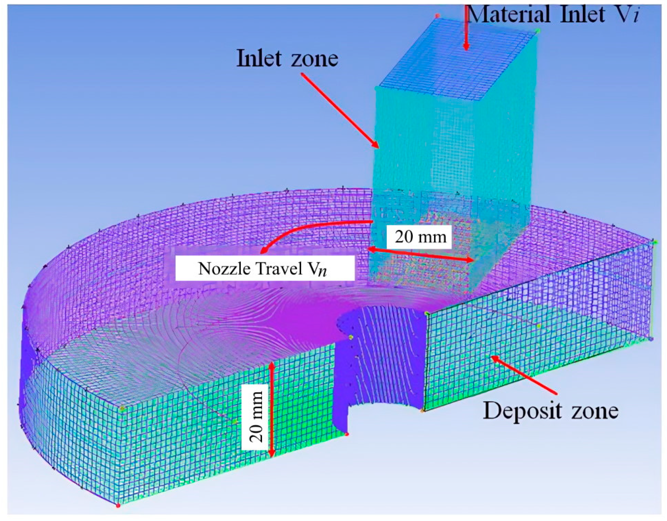
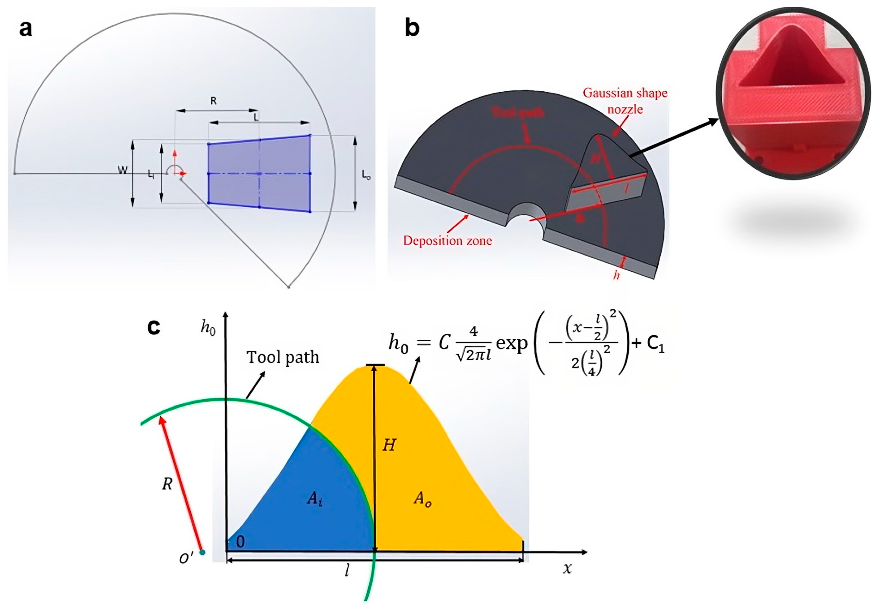
The simulation domain is shown in
Figure 1. It is composed of a vertical inlet zone and a horizontal deposit zone. Depending on the investigated nozzle shape, the vertical inlet zone is meshed with approximately 31 radial points, 21 angular points, and 31 vertical points. The horizontal deposit zone is meshed with 161 angular points, 46 concentric circles, and 21 vertical points. The largest cell size is smaller than 1 mm
3. The node number of the mesh is 175,707 when the mesh independence is reached. A stream of cementitious material is fed into the inlet zone, which then flows into the deposit zone. The ANSYS FLUENT 2022 R1 commercial software (ANSYS, Inc., Canonsburg, PA, USA) was used to perform the numerical simulation. The model geometry was meshed with the preprocessor ICEM CFD 2022 R1 software (ANSYS, Inc., Canonsburg, PA, USA) and imported to ANSYS FLUENT 2022 R1. A segregated time-dependent solver was used. The uniform inlet velocity of the concrete paste was applied, and the outlet is atmospheric pressure. The PRESTO software was selected for the pressure interpolation, and the PISO was selected for pressure–velocity coupling. A second-order up-wind differentiating scheme is used for differentiating the momentum equation. The implicit body force treatment was implemented for body force formulation. In addition, the time scale was set as Δ
t = 5 × 10
−4 s, and the relaxation factor was adjusted to ensure convergence. Details of the simulation procedures are reported in the authors’ previous work [
8].
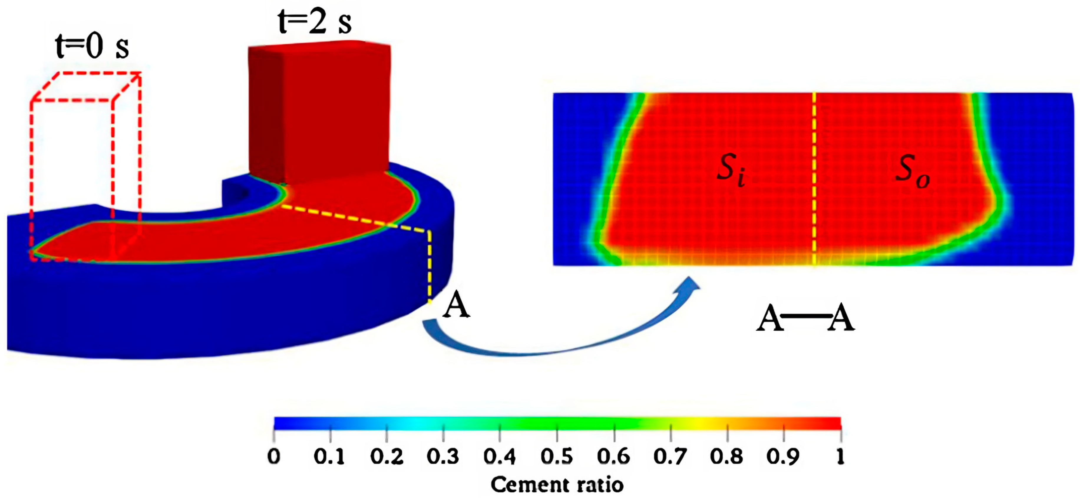
An exemplary result of the extrusion and deposition process of the cementitious material with a radial toolpath is depicted in
Figure 2. It should be noted that in the simulation, the nozzle only commenced its motion after the initial extruded material was deposited. This process was deliberately modelled so that the influence of the initial deposit process on the mass distribution of the printed material at corners could be eliminated. The simulation was terminated when the deposition process time lasted for approximately 2 s. As shown in
Figure 2, material mass distribution ratio (ϕ) refers to the ratio of the inner side cross-section area (
Si) that is close to the corner center to the outer side cross-section area of the printed filament (
So), i.e., ϕ =
Si/
So. In this study, ϕ is evaluated at the plane where the material was deposited for nearly 1.5 s so that the effect of deposition time has no influence on the mass distribution of the printed filament.
3. Results and Discussion
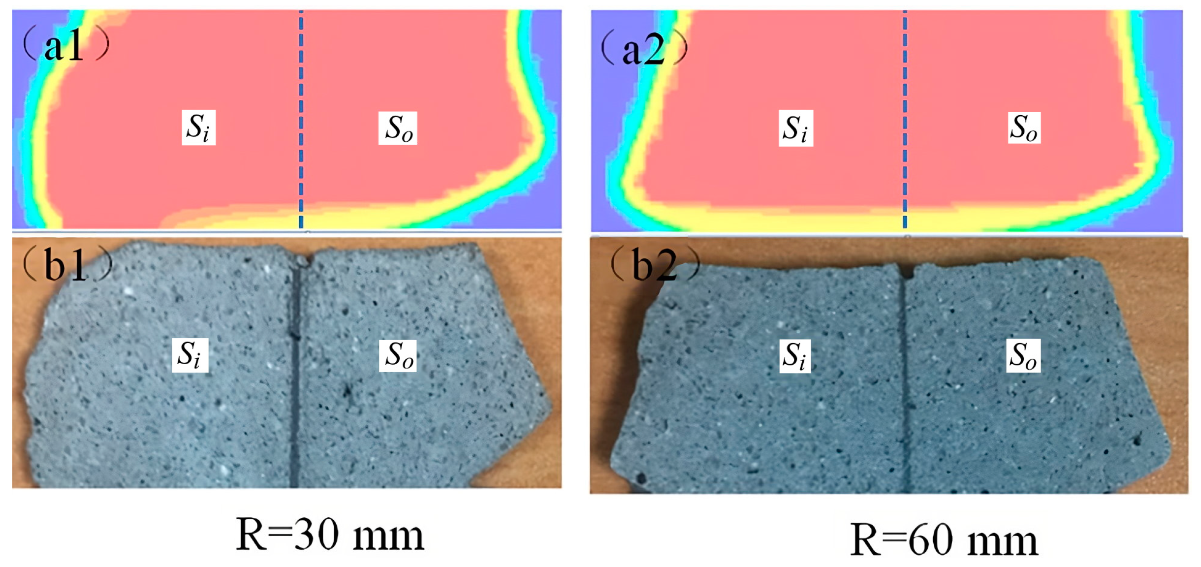
To demonstrate the influence of radial toolpath on material mass distribution, a time-dependent numerical simulation of the cementitious material extrusion and deposition process in ambient air was performed. It should be emphasized that, in order to validate the accuracy of our 3D simulation model, the simulation results obtained from our model were compared against the experimental results. The detailed comparisons are reported in Ref. [
8], and the pictorial comparisons are extracted as
Figure 3. In
Figure 3a, the material used in the experiment is composed of cement (OPC, CEM I 42.5, EnGro), fine sand, fly ash (Class F, Jaycee), and silica fume (Microsilica Grade 940, Elkem). To ensure the homogeneity of the cementitious mixture, the mixing process was carried out by firstly dry mixing all of the powder ingredients at 18 rpm for 3 min. This was then followed by the remixing of water with superplasticizer and adding them to the cement mixture. This mixing procedure lasts about 1 min at 33 rpm, followed by 2 min at 61 and 113 rpm each. Finally, the fresh cementitious material is further mixed for 1 min at 61 rpm. The aforementioned mixing procedures were developed from our past studies in which rheological test conducted demonstrated good homogeneity to a millimeter length scale [
10]. The properties of the cementitious materials, which are also used in the simulations in this study, were measured and listed in
Table 1. As shown in
Figure 3, the simulation results fit well with the experimental results, indicating that the proposed 3D simulation model can be used to study the material distribution in the 3DCP process.
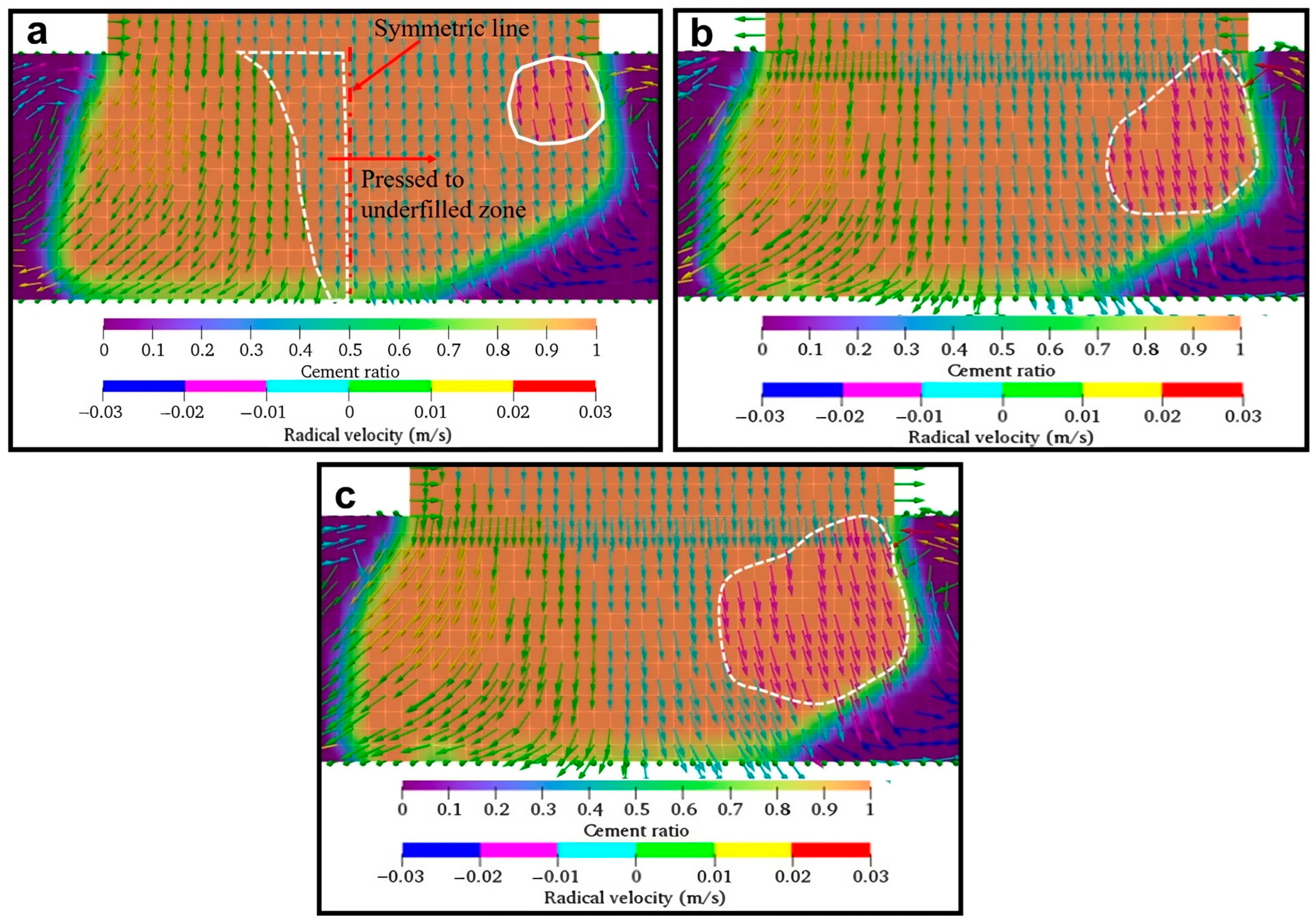
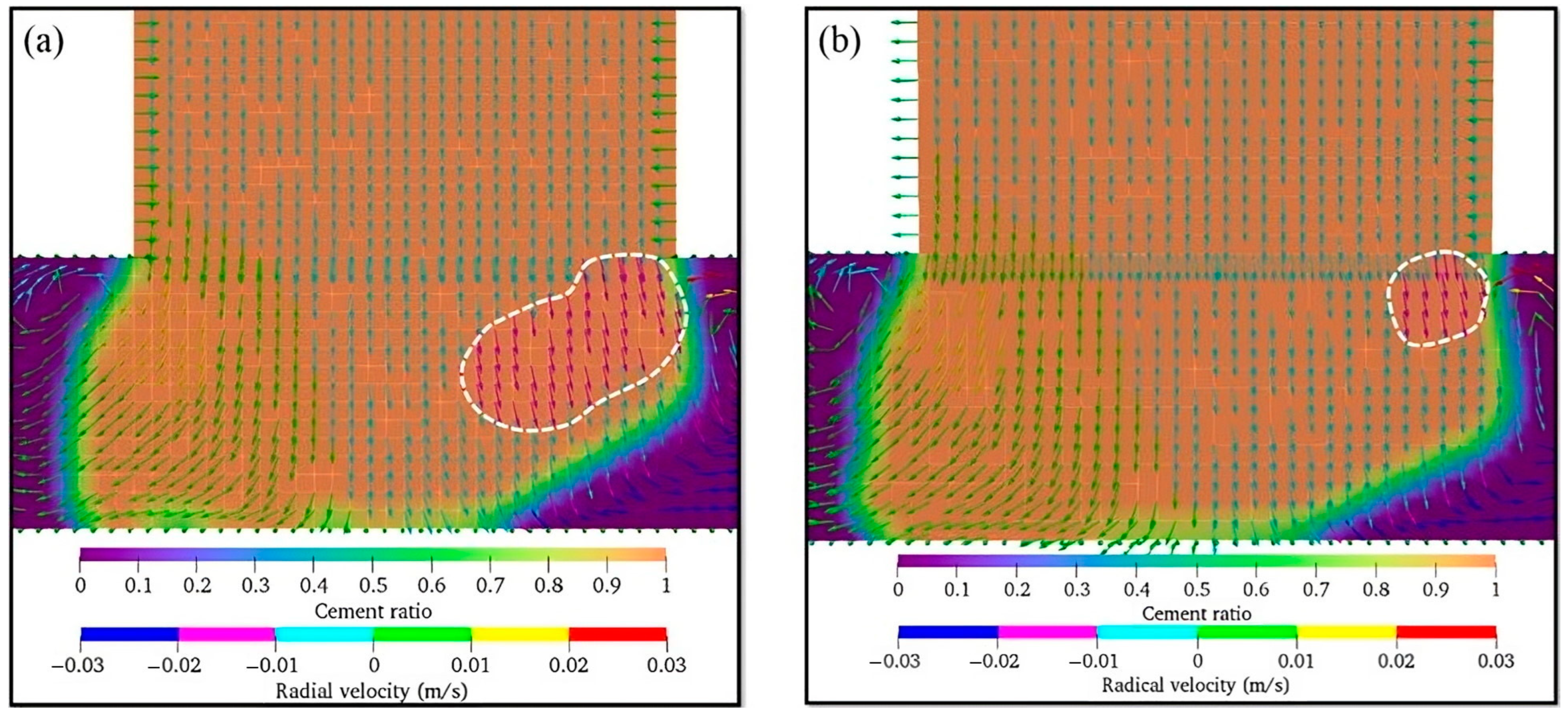
Figure 4 shows the material mass distribution of the filament cross-section during deposition. Here, the simulation was performed with a constant
R value of 30 mm and the rectangular nozzle of φ = 2, which corresponds to the nozzle length (
L) of 30 mm and width (
W) of 15 mm. In order to reduce the fabrication time while improving the surface finishing of construction scale printings, rectangular nozzles are implemented in 3DCMP to fabricate rectangular filaments to compose smooth straight walls. In this study, the low
R and high φ values were rationally selected, as they represent a more stringent condition in which a high degree of non-homogeneity in the filament occurs during deposition. While maintaining these two parameters, ξ ranged between 1.00 and 1.10. It should also be emphasized that ξ denotes the ratio of material velocity as it exits the nozzle (
Vi) to the nozzle tangential velocity (
Vn). Hence, with a constant
Vi, a larger ξ value denotes a lower
Vn.
It can be seen from
Figure 4 that the mass distribution of the deposited filament is highly non-homogeneous. For all ξ values, the mass distribution is skewed towards the left (or towards the center of the radial toolpath) where more material is deposited, which is very different comparing to the material which just comes out from a rectangular nozzle [
14]. On the contrary, on the right segment of the filament (or segment of the filament further away from the center of the radial toolpath), there exists an empty space that is not occupied by the material. This left-side bias deposition of material is mainly due to the presence of centripetal force acting on the material and pulling it towards the center as the nozzle negotiates a radial toolpath. This explanation can be further verified by comparing the material velocity magnitudes (shown in arrows in
Figure 4) under different ξ values. Even though the right segment of the filament is underfilled, the high-velocity zone (shown in red arrows and circled in white) still exists. Due to the reduction in centripetal force with the increase in ξ, it can be seen that the region of the high-velocity zone also increases. The high-velocity zones also indicate that more materials are pushed to the right segment of the filament, hence, improving the uniformity of material distribution. Using ϕ as the parameter to characterize mass distribution homogeneity, it was determined that the increase in ξ from 1.00 to 1.15 improves mass distribution homogeneity as ϕ reduces from 1.35 to 1.23.
The influence of the nozzle aspect ratio on mass distribution is shown in
Figure 5, where φ is ranged between 1.5 and 2.0. To achieve these aspect ratios,
L was fixed at 30 mm, and
W values at 15 mm and 20 mm were used. Arising from the conservation of mass, the layer thickness of the deposited filament is directly related to the nozzle width, i.e., a nozzle with smaller φ (or larger
W) produces a larger layer thickness. This can be clearly observed in
Figure 5, where the layer thickness for φ = 1.5 (
Figure 5a) is larger than φ = 2.0 (
Figure 5b). Furthermore, it is also apparent from the figures that a larger layer thickness (or smaller φ) results in an improved homogeneity of the filament as compared to the extrudate with a smaller layer thickness (or larger φ), i.e., as φ decreases from 2.0 to 1.5, ϕ changes from 1.25 to 1.21. Owing to the larger layer thickness, the filament weight is increased, increasing the force it exerts on itself to press the filament towards the base. As a result of this mechanism, the unfilled zone on the right segment of the filament deposited by the nozzle with φ = 1.5 is significantly reduced when compared to the filament that is deposited using a nozzle with φ = 2.0.
It can be concluded from the aforementioned analysis (
Figure 4 and
Figure 5) that conventional rectangular nozzles are inadequate to provide uniform material distribution at corners. When the R value is fixed, the non-homogeneity of the material distribution increases as ζ and φ increase, which is also consistent with the findings reported in Ref. [
8]. This inadequacy of the rectangular nozzles in providing a uniform material distribution stems from the inertia-induced centripetal force pulling the material towards the center of the radial toolpath. To overcome this issue of non-homogeneity, it is then required to (1) increase the material deposition rate at the outer segment of the filament to compensate for the low mass distribution in the underfilled zone and (2) to decrease the material deposition rate at the inner segment of the filament to reduce the mass distribution in the overfilled zone. In this regard, a trapezoidal nozzle can be employed to control the material deposition rate across the filament to enhance the extrudate uniformity. A top-view schematic of a trapezoidal nozzle is shown in
Figure 6a, where
Li and
Lo represent the parallel sides of the trapezium, with
Li having a shorter width and
Lo having a longer width;
W denotes the width of the trapezium at the mid-point and
L is the length of the trapezium. For the case where the length ratio (
LR) of the trapezoidal nozzle is greater than 1, where
LR =
Lo/
Li, and considering that material exit velocity (
Vi) is uniform, it will result in more material being deposited on the outer segment of the filament to compensate for the underfilled zone.
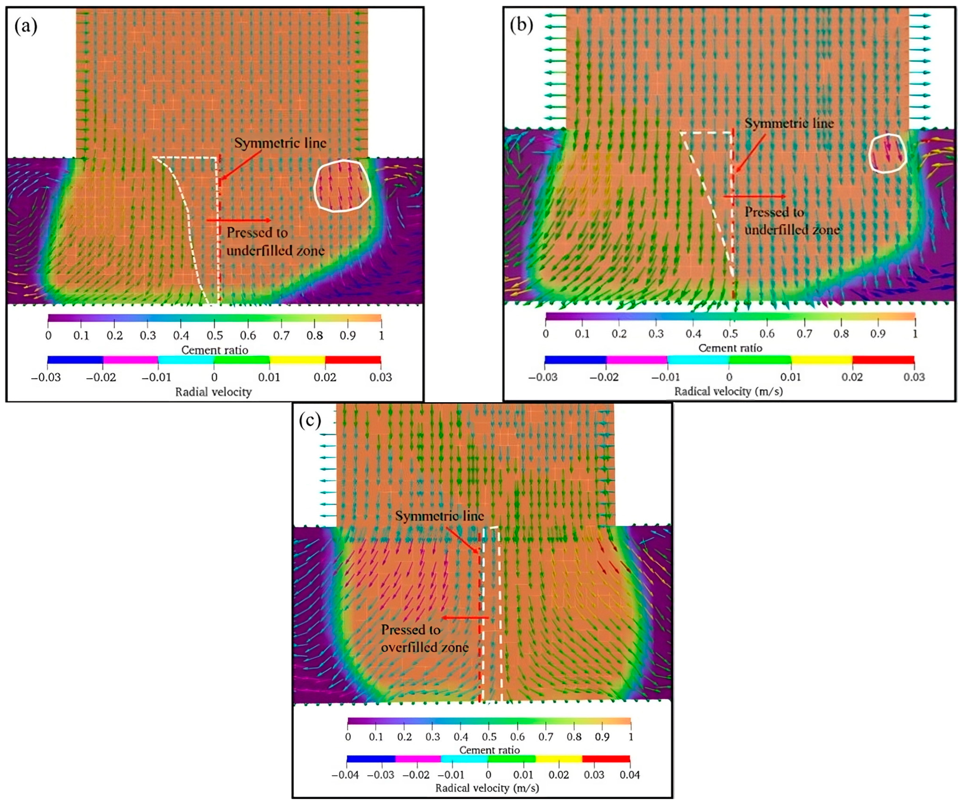
To validate this hypothesis, additional numerical simulation was performed on a trapezoidal nozzle of
LR = 1.2 and φ = 2.5 and the filament mass distribution was compared with a rectangular nozzle of the same φ value, i.e., φ = 2.5. Here,
LR = 1.2 is selected to compensate for the material distribution inhomogeneity of the rectangular nozzle based on the simulation result. A comparison of the material mass distribution is depicted in
Figure 7, where
LR = 1.0 (
Figure 7a) represents the rectangular nozzle. It can be clearly observed from the comparison of the two figures that the unfilled zone at the outer segment of the filament (blue region underneath the material) is significantly reduced when the trapezoidal nozzle is used. In all, the trapezoidal nozzle achieves a lower ϕ value of 1.24 as compared to the ϕ value of 1.29 for the rectangular nozzle. To further improve the homogeneity of the deposited material, trapezoidal nozzles with larger
LR ratios should be used. The increase in
LR introduces more materials on the outer segment of the filament and has the advantage of gravity-induced filament filling (see explanation in
Figure 5 in the previous paragraph for the detailed illustration of this mechanism). However, when the
LR becomes too large and the
Li value reduces significantly, nozzle clogging can be a concern. Furthermore, with one control parameter, i.e., the
LR ratio, to vary the extrudate material distribution, improving material homogeneity below an ϕ value of 1.20 for small toolpaths can be challenging.
To overcome the drawback of the trapezoidal nozzle, we further explored the utilization of Gaussian-shaped nozzles. As shown in
Figure 6b,c, the width of this nozzle varies with the nozzle length and takes the form of a Gaussian distribution. The Gaussian profile can be characterized by Equation (5) where
h0 denotes the nozzle length, and
H and
l are the maximum nozzle length and width of the Gaussian-shaped nozzle, respectively. In addition, µ and σ are the mean and standard deviations, and
C and
Cl are constants which can be used as fitting parameters to realize the desired Gaussian profile. Such a nozzle shape has several advantages over rectangular and trapezoidal nozzles. Firstly, studies have shown that the Gaussian nozzle produces a lower Poiseuille number when compared to rectangular and trapezoidal nozzles [
15]. This reduces the tendency of nozzle blockage due to high differential pressure [
16] and enables a continuous and smooth flow of materials. Secondly, the four fitting parameters of Equation (5) also increase the design freedom for the optimized Gaussian profile to achieve the required mass distribution when compared to the trapezoidal nozzle. For consistency of comparison,
C and
Cl in Equation (5) are set at the values of 432 and −1.9, respectively; µ =
l/2 and σ =
l/4 are chosen in Equation (5), such that the cross-section area is approximately the same as the rectangular and trapezoidal nozzles. The cross-section of the fitted curve is shown in
Figure 6c.
Figure 8 shows the comparison of the material mass distribution of the filament extruded and deposited from the various nozzles at ξ = 1. It can be seen that the mass distribution of the filament is clearly more uniform (ϕ = 0.98) when the Gaussian-shaped nozzle is used, and there are no unfilled and underfilled zones. In contrast, an unfilled zone still exists when the trapezoidal nozzle is used. As shown in
Figure 8c, the boundary of the toolpath is skewed towards the left side of the Gaussian profile, such that
Ai is less than
Ao. This allows more materials to be deposited on the outer segment of the filament to compensate for the centripetal effect. Furthermore, this outer segment also has a large maximum nozzle width (
H) which increases the material mass and assists in pushing the filament towards the base, eliminating the unfilled zones.


