1. Introduction
The motion of bodies in a rotating fluid is an object of great interest. We encounter rotational motion every day, as it is an integral part of many devices used in everyday life. The planets of the Solar system could be an example of systems in which the movement of fluid occurs against the background of rotation. A number of additional forces appear in the rotating system, such as the Coriolis force and centrifugal force of inertia. The complex behavior of the fluid in this case requires a comprehensive, experimental and theoretical study.
The features of the motion of a body in a rotating fluid were considered about one hundred years ago by Taylor [
1], who showed that the motion of a fluid in a rapidly rotating cavity is two-dimensional; the flows excited by a solid spherical body moving in a rotating fluid were later called Taylor–Proudman columns (Greenspan [
2]). The papers (Moore and Saffman [
3], Maxworthy [
4]) are devoted to theoretical and experimental studies of the drag experienced by a sphere moving in a low-viscosity fluid in a rotating cylinder of finite length. The articles (Moore and Saffman [
5], Maxworthy [
6]) present further development of this topic. The governing parameters are the Ekman number,
and the Rossby number,
, where
is the kinematic viscosity,
is the body radius,
is the body velocity, and
is the angular velocity of cavity rotation. The main attention in theory and experiments was directed to the study of the structure of flows and forces acting on a body. A large number of papers have been devoted to the study of the problem of motion and flow around a body moving in a rotating fluid after these pioneering works. A list of these works can be found in (Minkov et al. [
7]; Stone [
8]; Tanzosh and Stone [
9]). These studies also include the movement of drop inclusions in rotating liquids (Bush et al. [
10]). The problem of capturing the Taylor column phenomena numerically attracts great attention of scientists nowadays: the review of scientific results in this direction can be found in (Sahoo et al. [
11]); the article (Sarkar et al. [
12]) is devoted to the influence of magnetic fields in the control of the Taylor column phenomenon.
The boundary of the Taylor–Proudman column is formed by the Stewartson boundary layer (Stewartson [
13]). Its function is to ensure the continuity of the azimuthal flow velocity between the internal content of the column and the external surrounding fluid. An actual problem is the stability of the Stewartson layer (stability of the Taylor–Proudman column). This problem is well studied theoretically and experimentally in the case of the differential rotation of the body in a rotating fluid (Schaeffer and Cardin [
14], Hollerbach [
15], Hollerbach et al. [
16], Kozlov et al. [
17]). At this, the fluid motion in the form of Taylor–Proudman columns appears in the absence of longitudinal or transverse body motion.
Consider in more detail the practically important case: the motion of a rigid spherical body in a rotating cavity of definite length, started in famous works (Moore and Saffman [
3], Maxworthy [
4]) where the theoretical description and experimental study are done. It is shown that the drag force acting on the spherical body, moving along the axis of a rotating cylinder, is about twice as large as theoretically predicted in the limit of infinite cavity length and high rotation velocity. It happens because of the interaction of the Taylor columns in front and behind the moving body with the cavity end-walls. Outside these columns, in the limit of high rotational velocities (small Ekman numbers), the liquid performs an unperturbed solid-state rotation together with the cavity. At this, the fluid flows around the body only in a thin viscous Ekman layer, which forms near the body surface. All this leads to the generation of a vortex motion in the Taylor–Proudman columns themselves, retrograde in the frontal column and prograde in the column behind the moving body.
Ungarish and Vedensky [
18] considered, theoretically, the motion of a disk rising steadily along the axis in a rotating fluid between two infinite plates. In the limit of zero Rossby number and with the disk in the middle position, the ‘exact’ solutions for arbitrary values of the Ekman number, and relative cavity length,
, was found. The investigation is focused on the drag and the flow field when
E is small (but finite) for various
.
The numerical solution on the disk moving in a ‘short container’ was found in (Minkov et al. [
19]). The numerical solution is in good agreement with the exact linear solution (Ungarish and Vedensky [
18]) for a very small
, with the disk moving in the center of the container in a quasi-steady state. An important result is the solutions with a small
with the disk in a non-symmetric position. The differential rotation of a disk is found in this case. This result correlates with (Ungarish [
20], Ungarish and Vedensky [
18]), which by using the quasi-geostrophic model, estimated the influence of the non-symmetric position of the disk as follows: as the asymmetry increases, the drag increases monotonically but by a small amount, and the body acquires a small (compared to the value of the column rotation) differential angular velocity, which is prograde when the height of frontal Taylor column is larger than the rear one, and vice versa.
As can be seen from the literature review, the bulk is theoretical research, and the number of experimental studies is limited. Known experimental studies refer to relatively large Rossby numbers (Pritchard [
21]), or relatively large Ekman numbers (Makarikhin et al. [
22]), or drops motion (Bush et al. [
10]). To the best of our knowledge, with the exception of the famous works by Maxworthy [
4,
6], in which the main attention was paid to the drag force and the structure of flows around a spherical body moving with a given velocity along the axis of a rotating cavity, experimental studies of the dynamics of a free sphere moving in a rotating cavity of finite length at small Ekman numbers and small Rossby numbers, are absent.
The purpose of the present study is to experimentally study the motion of a free spherical body in a vertical rotating cavity of finite length during fast rotation (at low Ekman numbers) and low Rossby numbers using modern methods for measuring the velocity fields. The results of drag force are in agreement with experiments of Maxworthy [
4], and tends to the theoretical value (Moore and Saffman [
3]) with further decrease in Rossby and Ekman numbers. The differential rotation of the moving body is found and investigated versus the body position in the cavity and its axial velocity. The phenomenon of Taylor column instability is found.
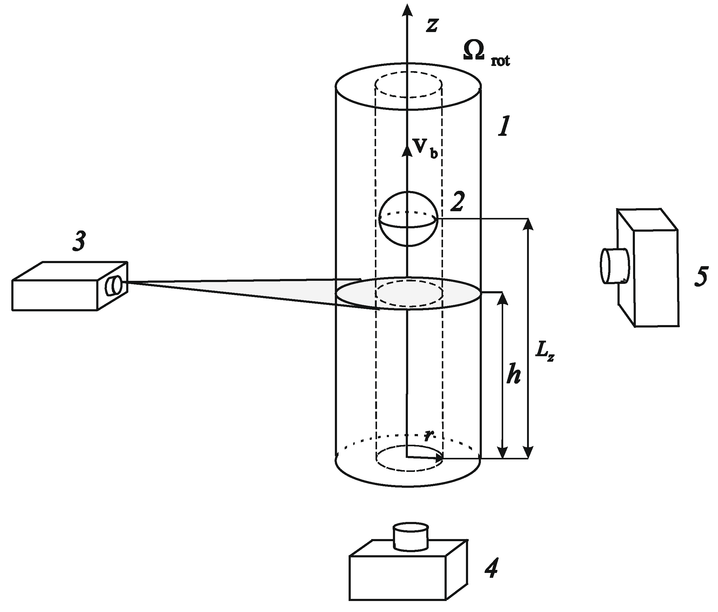
2. Experimental Setup and Methodic
The experimental setup (
Figure 1) consists of a cylindrical cell
1, in which there is a light spherical body
2 and a stepper motor providing the cuvette rotation. One of the ends of the cuvette is fixed in a large-diameter ball bearing. The transparent wide flange of the cell, fixed in this ball bearing, serves to observe the movement of the liquid and study of the azimuthal velocity field in the cross sections of the rotating cylinder at various heights (distance from the bottom flange). At the other end of the cylinder there is an easily removable flange, which is mounted in a conventional ball bearing. This flange has a hollow axis that serves to fill the cuvette with working fluid. The axis is connected through a coupling to a stepper motor, which rotates the cuvette.
The cuvette is made of a plexiglass tube with an inner diameter of 5.3 cm and a length of 22.5 cm. To rotate the cuvette, a stepper motor FL86STH118-6004A with a driver SMD-4.2 and a DC source Mastech HY5005E are used. The signal to control the rotation of the motor is given by the generator of the Zet 210 Sigma USB module, connected to a computer. The rotational velocity varies in the range of rps and is set with a precision of rps. Here, is the angular velocity. The main results refer to the interval f = 10–21 rps when the body under the action of centrifugal force takes a stable position on the axis of rotation. The orientation of the cuvette in the gravity field (horizontal, at an angle to the horizon, or vertical) can change, including during the experiment. The vertical position of the cuvette is set with an accuracy of 0.5 degrees.
A light spherical body is a rubber ball with a diameter of 2.40 cm and a density g/cm3. Meridians and the equator are drawn on the ball with a marker, which allows one to follow its rotation.
To measure the rotation of the body relative to the cuvette, the latter has a longitudinal mark along its entire length. To study the velocity of the body movement and its rotation relative to the cavity in the process of ascent, a high-speed video filming of the body by a camera located on the side is used.
The purpose of this work is experiments with the use of water-glycerol solutions. The main experiments were carried out on liquids with density and kinematic viscosity:
g/cm
3 and
St (pure water); 1.12 g/cm³, 0.034 St; 1.17 g/cm³, 0.107 St. The use of water-glycerol solutions, the viscosity of which differed by two orders of magnitude, provided a change in the dimensionless rotational speed
(governing dimensionless parameter, characterizing the Ekman number,
) in a wide range
. At the same time, the use of relatively viscous liquids in experiments suppressed the effect of sedimentation in the centrifugal force field of light-scattering particles, used in the study of velocity fields by the PIV-method (Particle Image Velocimetry). The essence of the method is to measure the displacement of light-scattering particles in some selected section of the cavity during a known period of time. The choice of this method is determined by its efficiency (velocity fields are measured), as well as good software (Thielicke and Stamhuis [
23]).
The velocity fields in the cavity are studied in the cross sections at various heights, as well as in a vertical axial section. For this purpose, the light-scattering visualizer particles of almost zero buoyancy and a diameter of 20 µm are added to the working fluid. The location of the particles in the plane of the light sheet, which is created by a laser
3 (
Figure 1) of type KLM-532 with power 1W, is recorded by the immovable in the laboratory reference frame high-speed camera
4 of the type Optronis CamRecord CL600x2. To work with the camcorder, the application CoreView is used. The laser sheet thickness is 2 mm. A cross-correlation processing of the velocity field is carried out using the program PIVlab [
23].
The main task is to study the motion of the body and fluid in the reference frame of the cavity. To do this, the frequency of the video recording is selected equal to (or a multiple of) the rotation frequency, and due to the stroboscopic effect, the movement of the body and fluid is observed in the reference frame of the cavity. For example, at a rotation frequency of f = 15 rps, the recording frequency is 15 frames per second. It is important to note that, in this case, the exposure time for an individual frame does not exceed 0.3 ms. The latter provides a clear image of light-scattering particles moving along with the liquid on separate frames, which is necessary for the applicability of the PIV method. Thus, all the results of the body velocity and fluid velocity measurements refer to the differential motion of the body and fluid in a rotating frame.
When studying the velocity fields in the cross-section of the cavity behind the floating body, the setup is positioned strictly vertically so that the wide transparent flange is at the bottom (
Figure 1). In this case, the high-speed video camera is installed from below and its optical axis coincides with the axis of rotation.
When measuring the velocity fields in front of a moving body, the same technique is used, but the installation is turned over. The transparent bottom in this case is located on top, and the high-speed camera is installed above the transparent flange of the cavity.
Synchronously with the operation of the high-speed camera, which records the movement of the liquid in a given cross-section of the cavity, the position of the body along the length of the cavity could be recorded using a conventional video camera 5. The camera 5 is located on the side of the rotating cuvette. The records from a conventional camera by saving frames are processed using the program Image J. The synchronous registration using two cameras (high-speed camera 4 and the conventional one 5) allows one to correlate the velocity field in a certain section, with the position of the body relative to the bottom of the cuvette at the same moment.
Experimental methodology is the next. At the beginning of the experiment, the cavity located horizontally rotates with a given velocity while the body is on the axis of the cavity near its bottom. After that, the cuvette is placed vertically smoothly for 1–2 s. A light body located near the bottom of the cuvette begins to float in the gravity field. The perturbations introduced in this case into the motion of the fluid in the cavity are not significant, and the transient processes were completed before the body moved away from the bottom to a distance comparable to its diameter. Such a setup and method are original and have not been used in previous studies. It is quite effective given the long duration of the body ascent process, which takes from 10 to 10
3 s. At the moment, when the sphere starts to ascend, the high-speed video camera begins to capture the location of the light-scattering particles in the selected cross-section of the channel (at a distance
from the cavity bottom,
Figure 1). The recording continues during the process of the body floating. Simultaneously, camera
5, located on the side, captures the distance of the body from the bottom of the cavity
(
Figure 1). The video recording ends after the body reaches the top end. The experiment is repeated at different rotational velocities (
f = 10–21 rps) with different liquids (
St); the velocity field of the azimuthal motion of the liquid in the reference frame of the cavity is studied in the cross-section of different heights
both in the upper (in front of the body) and in the lower columns.
4. Discussion
As a unit of the body velocity, we use the value that characterizes the velocity of a sphere in an infinite viscous fluid in the Stokes laminar flow regime, when the force applied to the body is balanced by viscous friction. Under the conditions of the experiment, when the Archimedes force acts on the body, such a unit up to a numerical coefficient (1/18) coincides with the velocity of a free ascent of the sphere. Here —relative body density.
In this case, the dimensionless velocity of the body (control dimensionless parameter) takes the form
Thus, the selected parameter has a clear physical sense, which is the speed of the body ascent compared to no rotation. As another dimensionless parameter, we choose the dimensionless rotation velocity , which characterizes the ratio of the Coriolis force and the viscous force. In the literature, this parameter is often called the Taylor parameter, and its reciprocal is the Ekman number.
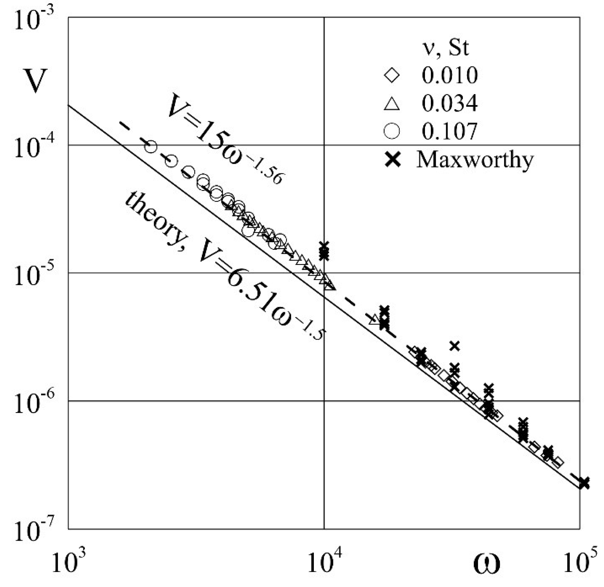
As can be seen from
Figure 8, all the experimental results obtained on liquids of different viscosities, with a variation in the rotation velocity over a wide range, are in good agreement with each other on the plane
and can be approximated by a single law
. The value of the Rossby number,
, corresponding to the experimental points in
Figure 8, could be estimated according to the formula
, in the experiments it varies in the range
. With regards to the Reynolds number,
, in our experiments its value is relatively small,
.
One can see a good agreement between our experimental data and the experimental results of Maxworthy [
6], represented by crosses in
Figure 8. Maxworthy used a different experimental technique and changed the Rossby number at a certain dimensionless rotational speed. At low Rossby numbers, our results coincide completely, and the distance of crosses from the theoretical curve in
Figure 8 (growth of
at certain
) is associated with an increase in the Rossby number.
The solid line in the figure shows the theoretical dependence (Moore and Saffman [
3]), which on the plane of the chosen parameters has the form
. The theoretical curve corresponds to the limiting case of low Rossby number,
, and high rotational velocity,
, when the dominant role is played by the Coriolis force. As can be seen, the experimental results are in good agreement with the theoretical curve, and at low
tend to approach it with an increase in the dimensionless rotation velocity.
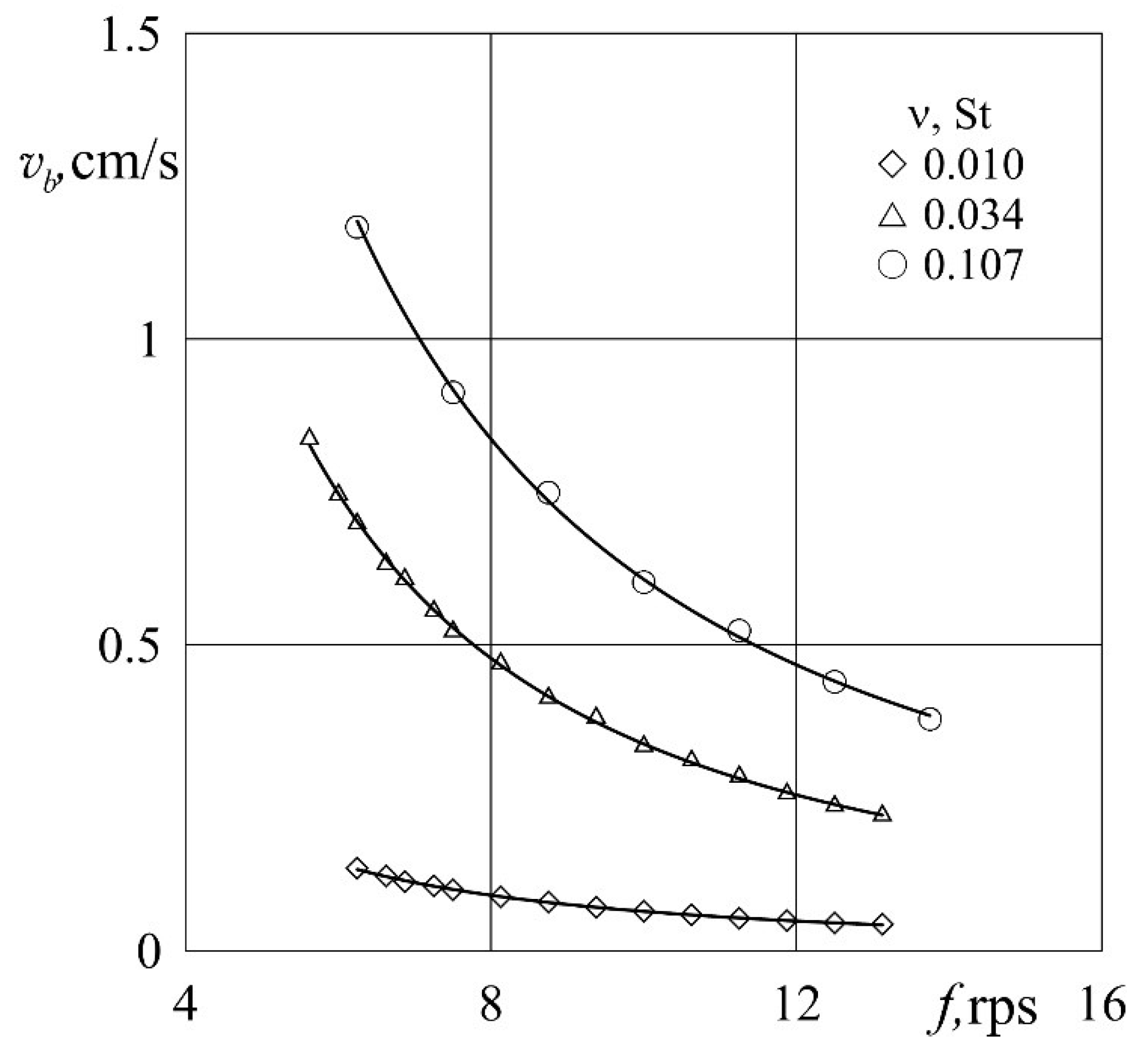
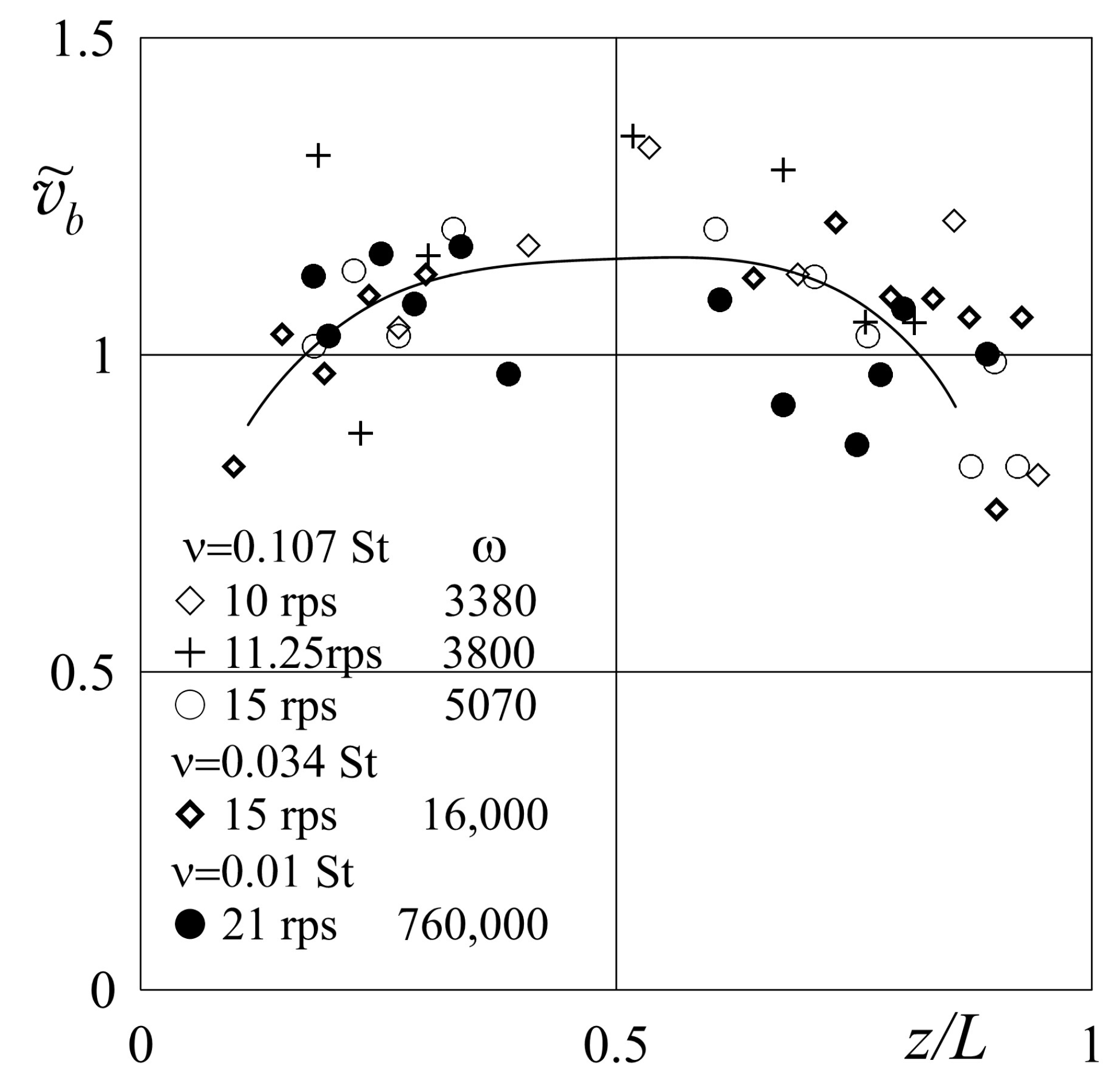
From
Figure 3, it follows that the velocity of the body ascent slightly and decreases near the ends of the cavity. At the same time, the dependences of the velocity on the coordinate obtained in liquids of different viscosities at different rotation velocities in
Figure 3 have a similar form, although they differ significantly in magnitude. Let us use the dimensionless velocity
, where the unit of measurement is the experimental mean velocity of the body (taking into account the dimensionless rotation velocity). This allows one to compare the results of measurements with different values of the dimensionless velocity of rotation (
Figure 9). As can be seen, the velocity distributions of the body along the length of the cavity at different values of the dimensionless rotation velocity are in satisfactory agreement with each other. This means that in the entire studied range of parameters, the longitudinal motion of the body obeys one law, and its intensity is determined by a single dimensionless parameter—the dimensionless velocity of the cavity rotation. At the same time, the velocity of the body remains almost constant along the entire length of the cavity.
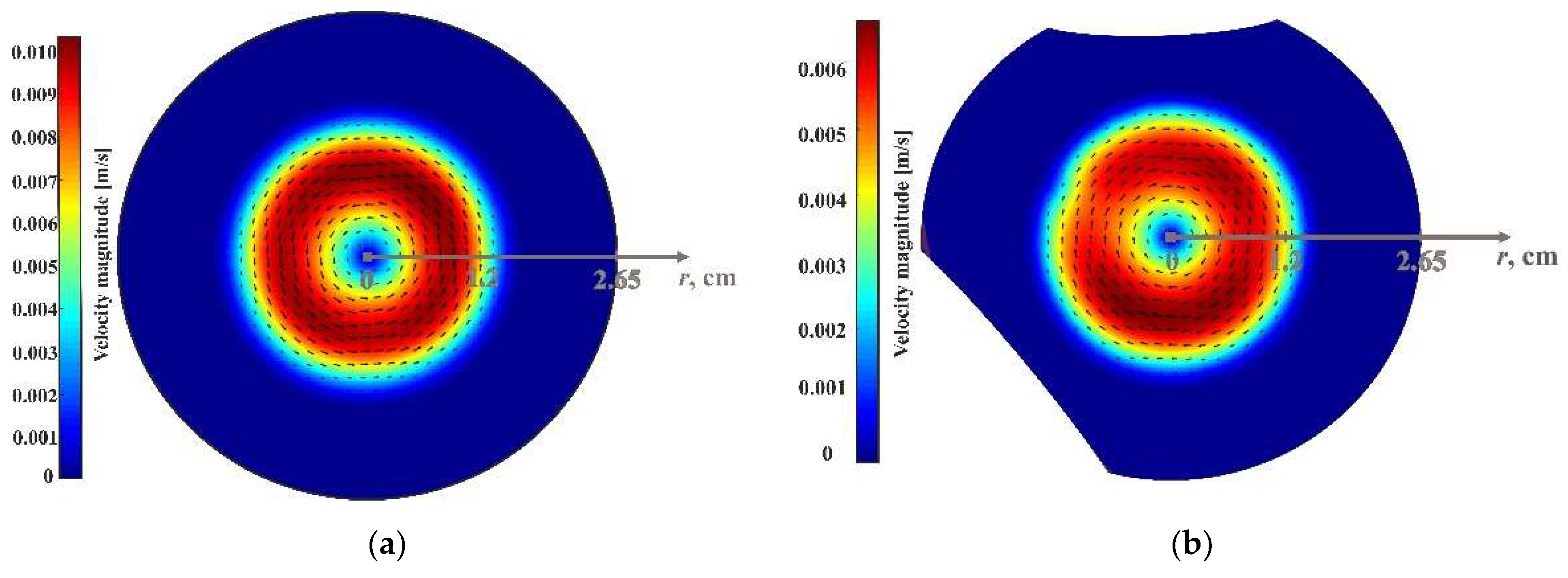
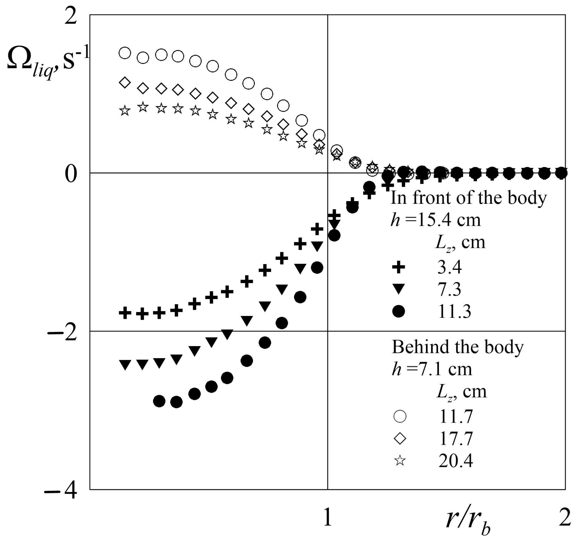
Let us dwell on the angular velocity of the liquid differential rotation in the reference frame of the cavity,
, depending on the dimensionless distance to the axis of rotation
(here
is the sphere radius). In
Figure 10, the experimental results of
Figure 7 are shown at the plane of these parameters. The points corresponding to very small distances from the axis of rotation are omitted, due to the significant relative error in measuring the distance to the axis. The dependences show that in the middle part of the Taylor–Proudman column, the angular velocity of the liquid rotation practically does not change; that is, the liquid rotates as a solid. This applies both to the frontal column (solid marks) and to the rear one (light marks). The angular velocity of the fluid rotation decreases with distance to the axis, and vanishes at a distance greater than the radius of the body by 20 percent, thereby showing the boundary of the Taylor–Proudman column. Note that the value of the angular velocity of rotation in both columns in the same way depends on their length; the shorter the columns, the higher the velocity of their rotation. The velocity of the retrograde rotation of the upper column increases as the body approaches the upper boundary, while the velocity of the prograde rotation of the lower column decreases.
What about the differential rotation of a body moving in a rotating cavity of finite length, when the distance to the ends of the cavity varies? This behavior was observed when performing numerical and analytical calculations (Minkov et al. [
19]) of the motion of a body in the form of a disk in a short cylindrical cavity. Despite the difference in the shape of the moving body (sphere and disk) and the relative length of the cavity (in our case
, and
in (Minkov et al. [
19])), we can conclude that the results are in good qualitative agreement; in the lower part of the cavity the body performs an advanced differential rotation, while in the upper part it lags behind. Let us dwell on the question of the nature of the body differential rotation. The rotation of the body is determined by the asymmetry of fluid motion in the frontal and rear Taylor–Proudman columns. In the case of an infinitely long cavity with symmetrical conditions on the end boundaries, this asymmetry is absent, and the rotation of the body is also absent (Moore and Saffman [
3]) and, conversely, if one end boundary is free and the other is solid, then this leads to the rotation of the sphere. The fact that there is no differential rotation of the body in our experiments when the body is in the middle of the cavity indicates that, in this case, the frontal and rearguard columns are identical and only rotate in opposite directions.
The analysis shows that all the results of the differential rotation of the body, obtained in experiments with different fluids at different cavity rotation rates, are consistent with each other if we introduce a dimensionless complex
. This complex characterizes the ratio of the tangential velocity of the equatorial point of a rotating body
to the velocity of its ascent
, when the body is at a distance of twice its own diameter from the middle of the cavity (where there is no differential rotation of the body). Interestingly, in the region
, the dependence obeys the law
(
Figure 11). It should be noted that a similar dependence of the differential velocity of rotation of the body on the dimensionless rotation velocity
is noted in (Ungarish and Vedensky [
18]; Minkov et al. [
19])), where the influence of the body position asymmetry was considered by using the quasi-geostrophic model.
The dependency change (
Figure 11) in the area
may indicate a qualitative change in the structure of the columns with a decrease in
. The answer to the question of what happens to the columns with a decrease in the rotation velocity follows from (Tanzosh and Stone [
9]). The paper shows that the column in front (behind) of a sphere moving along the axis of rotation changes qualitatively with distance. The column can be divided into regions (the Ekman layer, the geostrophic region, recirculating region, and the far zone) whose length depends on the dimensionless frequency. As the dimensionless frequency increases, the size of all zones, except for the Ekman layer, increase. For sufficiently large dimensionless frequencies, the dimensionless height of the Ekman layer scales as 2.5
, the geostrophic region as
and the recirculating region as
. The relative length of the working cavity (Taylor–Proudman column) in our experiments is
. Interestingly, this length qualitatively agrees with the boundary of the geostrophic region and the transition to a recirculation flow at
. This supports the assumption that the break in the dependence (
Figure 11) is associated with a change in the structure of the Taylor–Proudman columns, and the transition from the geostrophic flow regime to the recirculation regime with a decrease in the dimensionless rotation velocity.
The analysis shows that the differential rotation of a moving body is determined by the asymmetry of the frontal and rear Taylor–Proudman columns, the intensity of rotation of which decreases with their length. As a result of the fact that as the body rises, the length of the lower column increases, the upper column decreases, and the velocity of the differential rotation of the body changes. When the body is near the bottom of the cavity, the lower column which performs a prograde rotation plays a dominant role, as a result of which the body also performs a prograde differential rotation. Near the upper boundary the situation is reversed. With a decrease in the length of the upper column, which performs a retrograde rotation, and an intensification of its rotation, the body also acquires a negative differential rotation.
It should be noted that a body that performs the differential rotation in a rotating cavity (regardless of the mechanism for its generation) generates the motion in the form of a Taylor–Proudman column. Both halves of this column (on both sides of the body) perform the same rotation in the direction of differential rotation of the body, in the limit of large the rotation velocity of the column is half of the body rotation velocity. In the case under consideration, the resulting motion of the fluid in the columns is determined by the superposition of flows caused by the action of both mechanisms listed above: (a) rotation of the front and rear columns in opposite directions, caused by the moving body; (b) the rotation of both columns with the same velocity in the same direction, caused by the body’s differential rotation. The estimates show that the second mechanism can slightly enhance the observed phenomenon .
5. Conclusions and Plans
Experimental studies have shown that in the studied range of parameters, the longitudinal motion of the body is consistent with the theoretical calculations, and approaches them with an increase in the dimensionless frequency. In the frame of a rotating cavity, a body moving along the axis forms a two-dimensional Taylor–Proudman column, the diameter of which is consistent with the diameter of the sphere. The frontal part of the column performs a retrograde rotation, and the rear area a prograde one rotation. The intensity of the azimuthal rotation of the liquid in the cross sections of the columns decreases with an increase in their length.
It was shown that in a channel of finite length, the ascent velocity depends on the distance to the ends; near the ends, at a distance comparable to the diameter of the sphere, the velocity of the longitudinal motion of the body slightly decreases.
It is found that in a cavity of finite length () simultaneously with the movement along the axis, the free body performs a differential rotation relative to the cavity. The velocity of the rotation depends on the longitudinal coordinate of the body and the dimensionless velocity of cavity rotation. In the lower part of the cavity, the body performs a prograde differential rotation, and in the upper part, a retrograde one. In the middle (along the length of the cavity) there is no differential rotation of the body. It is shown that the differential rotation of the body is determined by the asymmetry of the anterior and posterior columns, which depends on the ratio of their lengths. It is shown that the velocity of the body’s differential rotation, and the rate of its change with the longitudinal coordinate, are determined by the dimensionless velocity of the body’s longitudinal motion and the frequency of the cavity rotation.
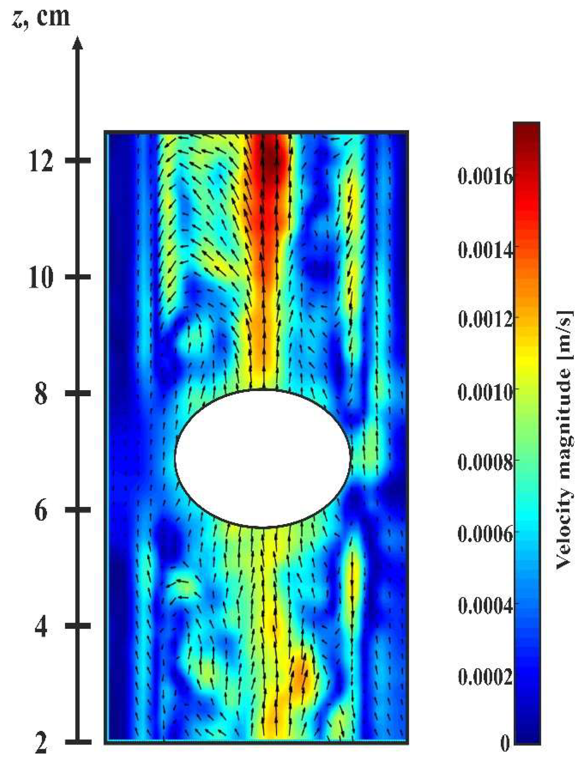
It is found that with an increase in the velocity of the body, the Taylor–Proudman column behind the body (that performs the prograde rotation) loses stability, and a system of longitudinal rolls develops on its boundary. The characteristic velocity field in the cross-section of the channel in the supercritical region is shown in
Figure 12. To the best of our knowledge, such instability of the Taylor–Proudman column, excited by the body moving along the axis of the rotating cavity, has been observed for the first time. The found phenomenon is an object of further experimental research.


