Article

CFD to Quantify Idealized Intra-Aneurysmal Blood Flow in Response to Regular and Flow Diverter Stent Treatment

1
Institute of Neuroradiology, University Hospital LMU Munich, 81377 Munich, Germany
2
Department of Informatics, Technical University of Munich, 85748 Garching, Germany
*
Author to whom correspondence should be addressed.
Fluids 2022, 7(8), 254; https://doi.org/10.3390/fluids7080254
Submission received: 15 June 2022 / Revised: 20 July 2022 / Accepted: 26 July 2022 / Published: 28 July 2022
(This article belongs to the Special Issue Image-Based Computational and Experimental Biomedical Flows)

Abstract

:
Cerebral aneurysms are pathological dilatations of the vessels supplying the brain. They carry a certain risk of rupture, which in turn, results in a high risk of mortality and morbidity. Flow diverters (FDs) are high-density meshed stents which are implanted in the vessel segment harboring an intracranial aneurysm to cover the entrance of the aneurysm, thus reducing the blood flow into the aneurysm, promoting thrombosis formation and stable occlusion, which prevents rupture or growth of the aneurysm. In the present study, the blood flow in an idealized aneurysm, treated with an FD stent and a regular stent (RS), were modeled and analyzed considering their design, surface area porosity, and flow reduction to investigate the quantitative and qualitative effect of the stent on intra-aneurysmal hemodynamics. CFD simulations were conducted before and after treatment. Significant reductions were observed for most hemodynamic variables with the use of stents, during both the peak systolic and late diastolic cardiac cycles. FD reduces the intra-aneurysmal wall shear stress (WSS), inflow, and aneurysmal flow velocity, and increases the turnover time when compared to the RS; therefore, the possibility of aneurysm thrombotic occlusion is likely to increase, reducing the risk of rupture in cerebral aneurysms.

1. Introduction

Cerebral aneurysms present a disease characterized by the local dilatation of arterial walls in the intracranial vasculature that generally occur on arterial curves and bifurcations in the circle of Willis [1]. The aneurysm may rupture and cause subarachnoid hemorrhage, which is associated with high mortality and morbidity [2]. A clinical study [3] reports that about 2% to 5% of the population is carrying such intracranial aneurysms.
In clinical practice, cerebral aneurysms are occasionally being discovered more frequently because of enhanced and widely utilized imaging technologies. Understanding the hemodynamic mechanisms involved is crucial for reducing the risk of rupture and hemorrhage in cerebral aneurysms and for identifying effective treatment options. Numerical methods may also offer good support for the medical treatment of brain aneurysms.
There are two approaches to effectively treating brain aneurysms. The first one is via clipping the aneurysmal neck and the other is via endovascular intervention. The advantage of the endovascular treatment is the fact that there is no need to do a craniotomy, exposing the surface of the brain vessel. Large or giant aneurysms, defined as wide-necked, dissecting, and fusiform aneurysms having a diameter ≥25 mm, are considered more challenging and less tractable to the traditional endovascular coiling [4]. While stent-assisted coiling and balloon-assisted coiling are alternative techniques developed to deal with such complex aneurysms, they offer less than desired efficacy, given their high rate of recanalization [5,6], and the flow diverter stent represents a paradigm change, with the intervention carried out in the parent artery [7,8]. The FD stent is a well-established method of endovascular reconstruction and aneurysm occlusion for large and complex intracranial aneurysms, with an overall porosity metallic mesh set in the parent artery to reduce the blood flow in the intracranial aneurysm to the point of stagnation and continuous aneurysmal thrombosis [9]. This phenomenon is affected by the metal surface area coverage provided by the stent. Rather than porosity, the pore density of the flow diverters seems to be a critical factor modulating device capability [10].
Computational techniques offer new capabilities in healthcare provision for cerebral aneurysms. The availability of a simulation tool for the flow diverter is extremely useful to support the decisions of treatment options by medical experts and to develop and optimize new implant designs.
Among several hemodynamic parameters that are discussed as key factors in the initiation, development, or rupture of intracranial aneurysms, one of the most studied parameters is the WSS. High or low local values of the WSS and non-uniform distribution of instability are negative conditions for the development of an aneurysm. Low WSS may lead to the spatial disorganization of endothelial cells and a dysregulation of antioxidant and anti-inflammatory mediators, resulting in arterial wall remodeling [11]. Consensually, high WSS may lead to the initiation of aneurysm formation, but its influence on growth and rupture is largely unknown. Tremmel et al. [12] suggest that both high WSS and low WSS could lead to rupture and growth of the aneurysm. Jou et al. [13] found that ruptured aneurysms had low WSS, whereas Shogima et al. [14] and Cebral et al. [15] suggested that high WSS was associated with ruptured aneurysms.
Several cerebral aneurysms have been effectively treated with flow diverter devices [16,17,18,19,20,21], albeit there have been reports of problems connected to late rupture [22,23,24,25]. These issues show that the aneurysms are not immediately protected following the procedure. Therefore, obtaining stable aneurysm occlusion quickly is necessary to improve the success of these treatments.
Goubergrits et al. [26] numerically studied the hemodynamic changes in the flow diverter device compared with a non-flow diversion device, rather than another stent; therefore, there is no information regarding the blood flow viscosity assumption. They conclude that the stenting does not affect the pressure in the cerebral aneurysm post-treatment, but significantly alters intra-aneurysmal hemodynamics through flow reduction and a change in flow pattern. Jou et al. [27] analyzed the flow behavior in a giant aneurysm using a CFD simulation, and they show that flow impingement is pointed as a significant factor for aneurysm initiation, growth, and burst. An impingement index is utilized to evaluate the size and effectiveness of flow impingement. However, the analysis was performed on pre-stent giant aneurysms. Chien et al. [28] investigated the hemodynamics of small unruptured and ruptured aneurysms at the same anatomical location, using simulation tools, and they concluded that the wall shear stress is an important parameter related to the development and rupture mechanism in brain aneurysms. This study shows the relevance of WSS, but considered only small aneurysms. Bouillot et al. [29] compared the hemodynamic characteristics in only medium-sized untreated cerebral aneurysm before and after the treatment with stents with different porosities. CFD simulations and particle imaging velocimetry (PIV) showed quantitative and qualitative evidence of the pressure and shear rate mechanisms driving the flow for both pre- and post-stent treated aneurysms, which is consistent which the findings in the present study.
Previous studies [30] show that the risk of rupture in large and giant aneurysms is higher than in small aneurysms. However, there are no studies regarding several hemodynamic changes in giant cerebral aneurysms treated with stents of different porosities and the non-Newtonian blood flow model.
The present numerical study investigates, in detail, the effect of stent porosity on hemodynamics in an idealized giant sidewall, wide-neck aneurysm. It might lead to a better understanding of failed aneurysm occlusion with flow-diverter stents.

2. Materials and Methods

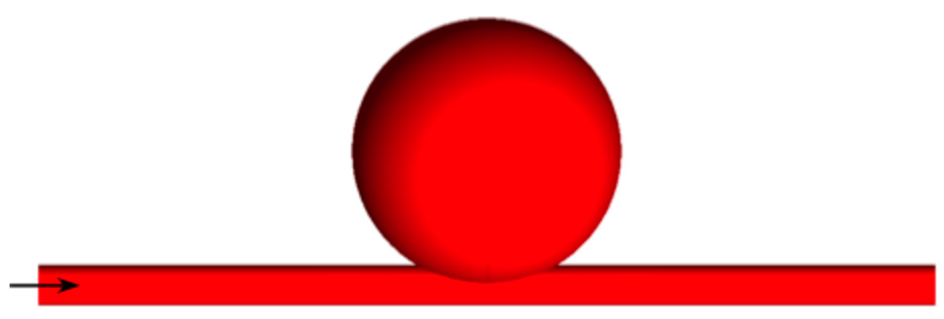
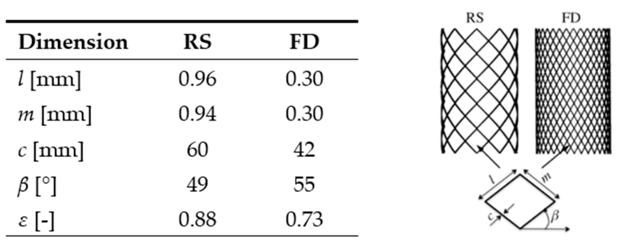
2.1. Vascular Modeling and Stent Geometry

An idealized giant saccular brain aneurysm, cf. Figure 1, is designed based on a 3D rotational angiography. A spherical aneurysm with a diameter of 33 mm is located at 2.0 mm above a straight cylindrical artery of diameter 4.5 mm. The distance of the artery inlet to the aneurysm proximal is 52 mm, and the length of the aneurysm distal to the artery outlet is also 52 mm. Thus, the inlet and outflow conditions were imposed far away from the location of the aneurysm, and the flow characteristics in the aneurysm were not affected.
Two stents with meshes made of cylindrical metal wires are considered which fit the shape of the parent artery. Their geometrical configuration is summarized in Figure 2 using a stent unit cell [31]. The stent with a low metal coverage proportion is called a regular stent (RS), and that with a high metal coverage proportion is known as a flow diverter stent (FD). The porosity ε, cf. Figure 2, of a stent is given by
ε = S w m S s
where S w m is the surface area of the stent without the material, S s the surface area of the stent, and ε is the porosity.

2.2. Numerical Grid and Mathematical Model

The computational meshing is created using the octree technique by the mesh generator software ICEM CFD v.19.2 (ANSYS Inc, Canonsburg, PA, USA). Due to the rapid variations of the hemodynamic parameters near the arterial wall, the numerical meshing consists of five prismatic layer elements near the wall surface, which are combined with tetrahedron grid cells into the flow region. Concerning the parent artery segment, covered with the stent devices, only tetrahedron grid cells are created. The distance of the first layer to the vessel surface is fixed to 0.01 mm with an average nodal space, increasing by a ratio of 1.2.
For the stent, the numerical grid is refined until the computed flow field is independent of the number of grid nodes. For the configuration with the regular stent, 11.4 million, and for the flow diverter, 11.9 million cells are used. The maximum velocities values obtained by the meshes were observed, and a difference of less than 2% was found in the results. For the untreated aneurysms, a similar mesh density (6.2 million) was computed to maintain the consistency between the huge number of elements. The stents have no deformation, due the flow interactions.
The blood flow is assumed as incompressible, and the unsteady Navier–Stokes equations are solved using the continuity and momentum equations [32,33], which are as follows
· u = 0
ρ ( u t + u · u ) = p + · τ
where u is the fluid velocity field, ρ is the fluid density, and p is the static pressure. τ is the deviatoric stress tensor
τ = μ ( γ ˙ ) ( u + u T   ) ,
where the superscript T denotes the transposed tensor and μ is the shear-dependent dynamic viscosity, cf. Equation (5).
The discretized governing equations are solved using the finite volume-based software platform OpenFOAM V3.1 (OpenCFDLtd, London, England), where a second-order upwind scheme for the convective terms is used, and a semi-implicit method for pressure-linked equations coupled with a solution scheme based on the algebraic multi-grid method is activated.
To close the system of equations, a constitutive law must be given to calculate the local fluid dynamic viscosity. The blood rheology literature provides a robust indication that the non-Newtonian behavior of the blood flow cannot be ignored [34]. Mainly, for predicting the risk of rupture in brain aneurysms, the accurate understanding of quantities such as the WSS and pressure distribution are crucial. Here, we assume the power-law Carreau–Yasuda viscosity model [35], a non-Newtonian viscosity model, to simulate shear-thinning blood, given by
μ = μ + [ μ 0 μ ] [ 1 + ( ( λ γ ˙ ) 2 ) ] ( a 1 2 ) ] ,
where μ 0 = 0.0456 Pa·s and μ = 0.0032 Pa·s are the asymptotic viscosities at zero and for infinite shear rate, respectively. The shear rate, which is a scalar measure of the strain rate tensor, is represented by γ ˙ . The relation time constant λ equals 10.03 s, and the power law index a is 0.344 [32].
In the present calculations, the inlet flow rate has been found [36] to be equal to the average values of the flow velocity in the internal carotid artery. A zero-pressure condition was used at the outlet. All the vascular walls are assumed rigid, with a no-slip boundary condition. In contrast to the substantial vessel wall motions in the aortic artery, the radial dilation of the arteries in the circle of Willis does not increase by more than 10% of its diameter [37].
The wall shear stress (WSS), recognized as one of the main risk factors for the aneurysm’s initiation, growth, and rupture, is analyzed [38]. The WSS is a viscous force, consisting of the tangential component of the stress tensor applied on the arterial wall. The stress tensor σ is given by [32]
σ = p I τ
where I is the identity tensor.
Thus, the WSS is represented by
σ n ( σ n · n ) n = τ n ( τ n · n ) n
where n is the normal vector to the arterial wall. σ n and τ n are the normal components of the stress and deviatoric tensors, respectively.
The intra-aneurysmal flow activity describes the aneurysm’s hemodynamics, which is quantified through the averaged magnitude of flow velocity in the aneurysm and the vorticity contours, which will be analyzed in the Results section. The wall distribution of the static pressure in both the untreated and treated aneurysm will also be studied. To quantify the stasis of the flow inside the aneurysm, the turnover time is given by
t t = V aneurysm ϑ inflow
which is defined as the volume of the aneurysm divided by the aneurysmal volumetric inflow rate at the neck. The magnitude of the average flow velocity is calculated to indicate the flow activity inside the aneurysm.

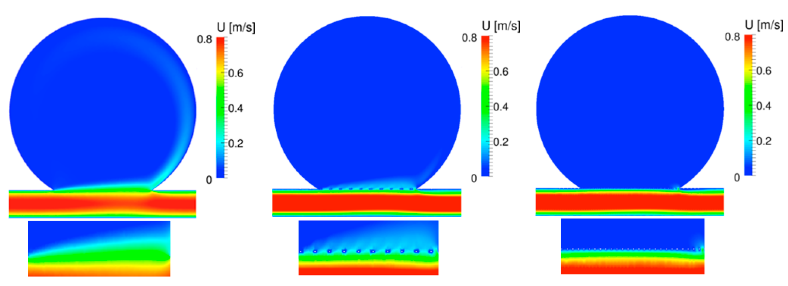
3. Results and Discussion

Simulations are performed for the untreated aneurysm (UA), the aneurysm with a regular stent (RS), and with a flow diverter stent (FD), cf. Figure 1 and Figure 2, to calculate the change in the intra-aneurysmal hemodynamics.
Speaking of the saccular intracranial aneurysms, measurement at the neck is important to identify the characteristics of the blood flow entering and exiting the aneurysm sac, providing more information about the growth of the aneurysm sac in time, without changing its shape. The dome is the region at which most ruptures occur. To investigate the rupture risk, knowing the hemodynamic properties in this area is necessary. Additionally, a change in the hemodynamics from the neck to the dome (i.e., measurements performed in the middle segment of the sac) could clarify the growth pattern, secondary bleb formation, and rupture risk of the aneurysm.
First, the maximum value of the WSS magnitude on the aneurysmal wall will be analyzed at the different cross-sections, as shown in Figure 3, i.e., at the neck of the aneurysm (A-A’), in the center (B-B’), and in the dome (C-C’). Table 1 and Table 2 show the maximum value of the WSS magnitude on the aneurysmal wall for the UA, RS, and FD for the systolic (0.17 s) and diastolic (0.78 s) cardiac flow, respectively. A strong reduction in the WSS for the different cross sections, for both the regular stent and the flow diverter, is observed. However, the WSS reduction of the flow diverter during the peak systole is more significant (up to 99.2% in the dome).
The huge variation in the reduction in the WSS between the RS and the FD occurs during diastolic cardiac flow in the aneurysm’s neck, where the RS shows a decrease in WSS of 45% and of 85% for the FD, respectively, compared to the untreated aneurysm. However, during the diastole, the WSS reductions in the center of the aneurysm are similar for the RS and the FD (88.7%), and present a significant discrepancy in the aneurysm neck, with 45% for the RS and 85% for FD.
Figure 4 and Figure 5 show the velocity contour and streamlines, respectively, of the systole, and Figure 6 and Figure 7 display the corresponding plots for the diastole. The contour plots show the cut at the mid-plane (B-B’), cf. top parts of Figure 4 and Figure 6, as well as a zoom of the neck region in the lower parts of those figures. The velocity streamlines refer to the 3D situation. Each figure shows the flow in the untreated aneurysm (left), the aneurysm treated with a regular stent (center), and treated with the flow diverter (right). Note that Figure 5 and Figure 7 show the placement of the RS (center) and the FD (right), which are omitted in Figure 4 and Figure 6 for a better visibility of the flow pattern in the aneurysm neck.
During the systole, the flow within the untreated aneurysm is characterized by a regular vortex located at the center of the aneurysm, cf. Figure 5, with inflow at the distal and outflow at the proximal edge of the neck. After the treatment with the regular stent, the flow pattern has similar characteristics as seen in the UA, with a slight displacement of the vortex towards the outflow of the cerebral aneurysm. After the FD implant, the flow field shows a separation of the vortex, where the main vortex circulates inwards towards the proximal side of the neck, as seen in the UA and RS situations, and a separated vortex rotates outwards from the proximal towards the distal side of the neck. The zoom view of the velocity contour plots in Figure 4 shows the strong impact of both the RS and the FD on the flow field in the neck of the aneurysm, which is accompanied by a strong decrease in blood flow into the cerebral aneurysm: the flow is shifted from the neck of the aneurysm towards the parent artery, and the performance of the stent devices is obvious. Note how the struts of the stent affect the velocity flow field. Notice that in the outflow region of the aneurysmal neck, the velocity profiles in both aneurysms treated with the RS and the FD, the flow widens somewhat upward, showing the critical region where a risk of rupture may occur in aneurysms treated with stent devices.
The flow diverter’s pore size, albeit sufficiently small to achieve flow re-channeling, is large enough to provide a scaffolding for the growing of endothelial and neointimal tissue across the aneurysmal neck [39]. Regarding the flow direction, the intensity of this effect is proportional to the stent porosity.
For the diastole shown in Figure 6 and Figure 7, the flow field in the UA is characterized by a regular vortex, which is slightly displaced towards the outflow of the aneurysm, with inflow at the distal and outflow at the proximal side of the neck. The velocity streamlines after the implant of the RS reveal some flow division close to the aneurysm’s neck, where the fluid circulates counterclockwise towards the distal inflow and clockwise towards the proximal outflow. This flow alteration is accompanied by a strong reduction in the absolute blood flow velocity in the aneurysmal neck and a shift of the peak values towards the parent artery. Both effects are strengthened by the implant of the FD, which shows its superior performance over the RS in this region. Thus, the numerical results clearly show that the flow impingement on the aneurysmal wall in the distal neck region reduces with decreasing stent porosity.
With the decrease in stent porosity, the magnitude of the vortical flow is decreased. Figure 8 and Figure 9 show the vorticity contours at the different cross sections marked in Figure 3. The magnitude of the vorticity perpendicular to the plane is displayed, where blue and red colors indicate clockwise and counterclockwise rotation, respectively. For all cross-sections, the magnitude of the vorticity is significantly reduced through the deployment of the RS and the FD; note the different scales used at the different cross-sections.
During the systole, inside the aneurysm, the rotation occurs from the proximal to distal for the UA, RS, and FD cases, to the neck, middle, and dome cross sections, as shown by Figure 8. During the diastole, as shown in Figure 9, the rotation pattern is the same, except for FD middle and dome of the aneurysm, which shows the direction from the distal to the proximal within the aneurysm.
The static pressure on the distal neck was decreased after both the RS and the FD implant, for both systole and diastole, as shown in Figure 10 and Figure 11. The mean static pressure in the middle and in the dome of the aneurysmal is not significantly affected by the implant treatment. The primary aim of the stent intervention is the prompt and extensive aneurysmal occlusion by improving the flow diversion, consequently creating favorable conditions to generate aneurysmal thrombotic occlusion, as well as the reconstruction of the parent vessel. An increase in the turnover time, will increase the intra-aneurysmal thrombotic activity, consequently providing a better chance of a successful treatment [40]. The turnover time increases with decreasing stent porosity, as shown in Figure 12. For the UA, a turnover time of 0.63 s is obtained, and it reaches a maximum of 1.4 s after the RS implant and 2.1 s after the FD treatment, respectively, for the systolic cardiac flow. For the diastole, the RS had a turnover time of 3.8 s and after the FD, 6.8 s, starting from 2.1 s for the UA. Thus, the FD again shows its superior performance compared to the RS.
The turnover time increases with decreasing stent porosity, as shown in Figure 12a. For the UA, a turnover time of 0.63 s is obtained, and it reaches a maximum of 1.4 s after the RS implant and 2.1 s after the FD treatment, respectively, for the systolic cardiac flow. For the diastole, the RS had a turnover time of 3.8 s and after the FD, 6.8 s, starting from 2.1 s for the UA. Thus, the FD again shows its superior performance compared to the RS. The average intra-aneurysmal flow, as shown in Figure 12b, decreases with an increased stent porosity. This reduced aneurysmal inflow can accelerate the blood clotting condition and the thrombotic occlusion in the aneurysm [41].
For the systole, the average of the flow velocity within the UA is 0.43 m/s, for the RS it is 0.23 m/s, and for the FD, 0.15 m/s is obtained. Considering the diastolic cardiac cycle, the average of the intra-aneurysmal flow for the UA is 0.13 m/s, for the RS it is 0.09 m/s, and 0.05 m/s for the FD. The WSS is higher on the distal neck compared to the proximal neck region of the aneurysm. With the RS implant, the WSS exhibits a strong reduction at the neck, middle, and dome areas of the aneurysm, for both the systole and diastole cardiac flows. However, with the FD implant, the reduction in the WSS is even more significant, avoiding the impact of the WSS on the distal aneurysmal wall.
In the untreated aneurysm, for both the systole and the diastole, the blood inflow into the aneurysm occurs with strong impingement on the distal aneurysmal wall, in a counterclockwise intra-aneurysmal flow. This flow entering the aneurysm is both pressure- and viscous shear-driven, as described by Meng et al. [42]. For the regular stent, a reduction in the velocity gradient occurs, and thereafter, a decrease, but not a complete extinction, in the inflow jet on the distal aneurysmal wall is observed. The implantation of the flow diverter obstructs the flow at the aneurysm neck, promoting a lower shear stress transmission, eliminating the inflow jet at the distal wall, and causing a rise of the pressure gradient along the parent artery. The pressure drives the circulating fluid inward and outward from the brain aneurysm at the distal and proximal sides, respectively.
The pattern of the velocity streamlines is consistent with the PIV experiments performed by Bouillot et al. [43], for the UA, RS, and FD. An exception is noted in the streamlines after the FD for the systole, which for that PIV experiments, showed complete dissolution of the single vortex, which does not happen in the present situation, where the single vortex resides with magnitude; however, the single vortex strongly reduces at all cross sections. These differences may be due the different sizes of the aneurysms studied, with a medium size for the experiment and a giant size in the present study. In the medium-sized aneurysm, the intracranial aneurysmal pressure is higher than the pressure at the proximal neck and lower than the pressure at the distal neck, causing a clockwise flow in the aneurysm. In the present giant aneurysm, a partial clockwise vortex is created beneath the center of the aneurysm, because the intra-aneurysm pressure is only slightly higher than that at the aneurysm proximal neck, which is not sufficient to create a complete clockwise flow within the aneurysm. Thus, in the giant cerebral aneurysm, there is an occurrence of both clockwise and counterclockwise flows in the intracranial aneurysm. The FD implantation is effective in reducing the velocity magnitude within the intracranial aneurysm, but it does not cause extinction of the single vortex in the giant aneurysm.
In agreement with the studies presented by Kerl et al. [44] and by Larrabide et al. [45], the intra-aneurysmal mean static pressure was not affected by the stents devices deployed, except for a small pressure change at the distal neck region. This change in pressure is due to stagnation of impingement flow in that region.
The difference in the reduction in the aneurysm inflow and the flow activity after the implantation of the regular stent and flow diverter stent is a key factor for thrombus formation inside the aneurysm. As the average intra-aneurysmal flow velocity decreases, the turnover time flow increases in an inverse proportion, and therefore, the chance of aneurysm thrombotic occlusion is likely to increase [12]. A delay at the complete aneurysm occlusion exposes the patients to prolonged use of blood-thinners, which in the meantime, could increase the risk of bleeding [46].

4. Limitations and Outlook

There are a few limitations in the present study, such as the assumption of the absence of fluid-structure interaction between the flow and the aneurysm [47,48], and the stent and the vessel. Furthermore, we are considering the flow as a single phase, neglecting the thrombus formation and growing effects and interaction with the stent. Further studies are planned to involve in-vitro and in-vivo 4D flow magnetic resonance imaging patient-specific image models to validate the simulations.

5. Conclusions

The flow diverter effectively reduces the wall shear stress and the blood flow velocity, while also providing a structure that supports the endothelization and reconstruction of the parent vessel. This device also decreases the vorticity magnitude and relocates the center of the vorticity in the intracranial aneurysm. The implantation of the FD does not affect the static cerebral aneurysm pressure. It was observed that due its low porosity, the use of the FD greatly improves the performance compared to the RS, promoting a more efficient reduction in the aneurysm inflow, in addition to an increase in the higher turnover time, and consequently, a gradual thrombosis formation. The hemodynamic alterations in the cerebral aneurysm blood flow dynamics by the deployment of the stent have the potential to induce intra-aneurysmal thrombosis, which is the objective of this treatment paradigm. Further studies are necessary to correlate hemodynamics with intra-aneurysmal thrombosis and to determine the optimum stent design for cerebral aneurysm applications.

Author Contributions

Conceptualization, A.F.S., Y.Ö. and T.L.; methodology, A.F.S.; software, A.F.S. and S.S.; validation, A.F.S.; formal analysis, A.F.S.; investigation, A.F.S.; resources, T.L.; data curation, A.F.S.; writing—original draft preparation, A.F.S.; writing—review and editing, A.F.S., Y.Ö. and T.L.; visualization, A.F.S.; supervision, T.L.; project administration, A.F.S. and T.L.; funding acquisition, T.L. All authors have read and agreed to the published version of the manuscript.

Funding

This research received no external funding.

Institutional Review Board Statement

Not applicable.

Informed Consent Statement

Not applicable.

Data Availability Statement

Not applicable.

Acknowledgments

The authors gratefully acknowledge the Gauss Centre for Supercomputing e.V. (www.gauss-centre.eu (accessed on 1 May 2020) for funding this project by providing computing time on the GCS Supercomputer SuperMUC at Leibniz Supercomputing Centre (www.lrz.de (accessed on 1 May 2020)).

Conflicts of Interest

The authors declare no conflict of interest.

References

  1. Willis, T. The Anatomy of the Brain and the Nerves, Tercentenary ed.; Feindel, W., Ed.; McGill University Press: Montreal, QB, Canada, 1965. [Google Scholar]
  2. Dennis, K.D.; Rossman, T.L.; Kallmes, D.F.; Dragomir-Daescu, D. Intra-aneurysmal flow rates are reduced by two flow diverters: An experiment using tomographic particle image velocimetry in an aneurysm model. J. NeuroIntervent. Surg. 2015, 7, 937–942. [Google Scholar] [CrossRef] [PubMed]
  3. Augsburger, L.; Reymond, P.; Rüfenacht, D.A.; Stergiopulos, N. Intracranial stents being modeled as a porous medium: Flow simulation in stented cerebral aneurysms. Ann. Biomed. Eng. 2010, 39, 850–863. [Google Scholar] [CrossRef] [PubMed]
  4. Möhlenbruch, M.; Herweh, C.; Jestaedt, L.; Stampfl, S.; Schönenberger, S.; Ringleb, P.; Bendszus, M.; Pham, M. The FRED flow-diverter stent for intracranial aneurysms: Clinical study to assess safety and efficacy. Am. J. Neuroradiol. 2015, 36, 1155–1161. [Google Scholar] [CrossRef] [PubMed] [Green Version]
  5. Shapiro, M.; Becske, T.; Sahlein, D.; Babb, J.; Nelson, P. Stent-supported aneurysm coiling: A literature survey of treatment and follow-up. Am. J. Neuroradiol. 2012, 33, 159–163. [Google Scholar] [CrossRef] [PubMed] [Green Version]
  6. Coley, S.; Sneade, M.; Clarke, A.; Mehta, Z.; Kallmes, D.; Cekirge, S.; Saatci, I.; Roy, D.; Molyneux, A. Cerecyte coil trial: Procedural safety and clinical outcomes in patients with ruptured and unruptured intracranial aneurysms. Am. J. Neuroradiol 2012, 33, 474–480. [Google Scholar] [CrossRef] [PubMed] [Green Version]
  7. Alderazi, Y.J.; Shastri, D.; Kass-Hout, T.; Prestigiacomo, C.J.; Gandhi, C.D. Flow diverters for intracranial aneurysms. Stroke Res. Treat. 2014, 2014, 1–12. [Google Scholar] [CrossRef]
  8. Becske, T.; Kallmes, D.F.; Saatci, I.; McDougall, C.G.; Szikora, I.; Lanzino, G.; Moran, C.J.; Woo, H.H.; Lopes, D.K.; Berez, A.L.; et al. Pipeline for uncoilable or failed aneurysms: Results from a multicenter clinical trial. Radiology 2013, 267, 858–868. [Google Scholar] [CrossRef]
  9. Girdhar, G.; Li, J.; Kostousov, L.; Wainwright, J.; Chandler, W.L. In-vitro thrombogenicity assessment of flow diversion and aneurysm bridging devices. J. Thromb. Thromboly 2015, 40, 437–443. [Google Scholar] [CrossRef] [PubMed]
  10. Sadasivan, C.; Cesar, L.; Seong, J.; Rakian, A.; Hao, Q.; Tio, F.O.; Wakhloo, A.K.; Lieber, B.B. An original flow diversion device for the treatment of intracranial aneurysms: Evaluation in the rabbit elastase-induced model. Stroke 2009, 40, 952–958. [Google Scholar] [CrossRef] [Green Version]
  11. Li, H.; Peng, T.; Wu, J.; Huang, C.; Jiang, Y.; Chen, L. Outflow vessel in the plane of main vortex of large cerebral aneurysms: A study of hemodynamic analyses. Neurosc. Med. 2015, 6, 65–70. [Google Scholar] [CrossRef] [Green Version]
  12. Tremmel, M.; Xiang, J.; Natarajan, S.K.; Hopkins, L.N.; Siddiqui, A.H.; Levy, E.I.; Meng, H. Alteration of intra-aneurysmal hemody-namics for flow diversion using enterprise and vision stents. World Neurosurg. 2010, 74, 306–315. [Google Scholar] [CrossRef] [PubMed] [Green Version]
  13. Jou, L.-D.; Lee, D.; Morsi, H.; Mawad, M. Wall shear stress on ruptured and unruptured intracranial aneurysms at the internal carotid artery. Am. J. Neuroradiol. 2008, 29, 1761–1767. [Google Scholar] [CrossRef] [PubMed] [Green Version]
  14. Shojima, M.; Oshima, M.; Takagi, K.; Torii, R.; Hayakawa, M.; Katada, K.; Morita, A.; Kirino, T. Magnitude and role of wall shear stress on cerebral aneurysm computational fluid dynamic study of 20 middle cerebral artery aneurysms. Stroke 2004, 35, 2500–2505. [Google Scholar] [CrossRef] [PubMed]
  15. Cebral, J.R.; Castro, M.A.; Burgess, J.E.; Pergolizzi, R.S.; Sheridan, M.J.; Putman, C.M. Characterization of cerebral aneurysms for assessing risk of rupture by using patient-specific computational hemodynamics models. Am. J. Neuroradiol. 2005, 26, 2550–2559. [Google Scholar] [PubMed]
  16. Wong, G.K.; Kwan, M.C.; Ng, R.Y.; Simon, C.H.; Poon, W.S. Flow diverters for treatment of intracranial aneurysms: Current status and ongoing clinical trials. J. Clin. Neuroradiol. 2011, 18, 737–740. [Google Scholar] [CrossRef] [PubMed]
  17. Steinman, D.A.; Milner, J.S.; Norley, C.J.; Lownie, S.P.; Holdsworth, D.W. Image-based computational simulation of flow dynamics in a giant intracranial aneurysm. Am. J. Neuroradiol. 2003, 24, 559–566. [Google Scholar] [PubMed]
  18. Kojima, M.; Irie, K.; Masunaga, K.; Sakai, Y.; Nakajima, M.; Takeuchi, M.; Fukuda, T.; Arai, F.; Negoro, M. Hybrid stent device of flow-diverting effect and stent-assisted coil embolization formed by fractal structure. Med. Biol. Eng. Comput. 2016, 54, 1–11. [Google Scholar] [CrossRef]
  19. Ley, D.; Mühl-Benninghaus, R.; Yilmaz, U.; Körner, H.; Cattaneo, G.F.M.; Mailänder, W.; Kim, Y.-J.; Scheller, B.; Reith, W.; Simgen, A. The derivo embolization device, a second-generation flow diverter for the treatment of intracranial aneurysms, evaluated in an elastase-induced aneurysm model. J. Clin. Neurol. 2017, 3, 335–343. [Google Scholar] [CrossRef]
  20. O’kelly, C.J.; Spears, J.; Chow, M.; Wong, J.; Boulton, M.; Weill, A.; Willinsky, R.A.; Kelly, M.; Marotta, T.R. Canadian experience with the pipeline embolization device for repair of unruptured intracranial aneurysms. Am. J. Neuroradiol. 2013, 34, 381–387. [Google Scholar] [CrossRef] [Green Version]
  21. Ma, J.; You, Z.; Peach, T.; Byrne, J.; Rizkallah, R.R. A new flow diverter stent for direct treatment of intracranial aneurysm. J. Biomech. 2015, 48, 4206–4213. [Google Scholar] [CrossRef] [PubMed]
  22. Cohen, J.E.; Gomori, J.M.; Moscovici, S.; Leker, R.R.; Itshayek, E. Delayed complications after flow-diverter stenting: Reactive in-stent stenosis and creeping stents. J. Clin. Neuros. 2014, 21, 1116–1122. [Google Scholar] [CrossRef]
  23. Kuzmik, G.A.; Williamson, T.; Ediriwickrema, A.; Andeejani, A.; Bulsara, K.R. Flow diverters and a tale of two aneurysms. J. NeuroIntervent Surg. 2013, 5, e23. [Google Scholar] [CrossRef]
  24. Hampton, T.; Walsh, D.; Tolias, C.; Fiorella, D. Mural destabilization after aneurysm treatment with a flow-diverting device: A report of two cases. J. NeuroIntervent. Surg. 2011, 3, 167–171. [Google Scholar] [CrossRef]
  25. Kulcsár, Z.; Houdart, E.; Bonafé, A.; Parker, G.; Millar, J.; Goddard, A.J.; Renowden, S.; Gál, G.; Turowski, B.; Mitchell, K.; et al. Intra-aneurysmal thrombosis as a possible cause of delayed aneurysm rupture after flow-diversion treatment. Am. J. Neuroradiol 2011, 32, 20–25. [Google Scholar] [CrossRef] [Green Version]
  26. Goubergrits, L.; Schaller, J.; Kertzscher, U.; Woelken, T.; Ringelstein, M.; Spuler, A. Hemodynamic impact of cerebral aneurysm endovascular treatment devices: Coils and flow diverters. Expert Rev. Med. Devices 2014, 11, 361–373. [Google Scholar] [CrossRef]
  27. Jou, L.D.; Mawad, M.E. Timing and size of flow impingement in a giant intracranial aneurysm at the internal carotid artery. Med. Biol. Eng. Comput. 2011, 49, 891–899. [Google Scholar] [CrossRef]
  28. Chien, A.; Tateshima, S.; Castro, M.; Sayre, J.; Cebral, J.; Vinueala, F. Patient-specific flow analysis of brain aneurysms at a single location: Comparison of hemodynamic characteristics in small aneurysms. Med. Biol. Eng. Comput. 2008, 46, 1113–1120. [Google Scholar] [CrossRef]
  29. Bouillot, P.; Brina, O.; Ouared, R.; Yilmaz, H.; Lovblad, K.-O.; Farhat, M.; Pereira, V.M. Computational fluid dynamics with stents: Quantitative comparison with particle image velocimetry for the three commercials off the shelf intracranial stents. J. NeuroIntervent. Surg. 2016, 8, 309–315. [Google Scholar] [CrossRef]
  30. Boussel, L.; Rayz, V.; McCulloch, C.; Martin, A.; Acevedo-Bolton, G.; Lawton, M.; Higashida, R.; Smith, W.S.; Young, W.L.; Saloner, D. Aneurysm growth occurs at region of low wall shear stress patient- specific correlation of hemodynamics and growth in a longitudinal study. Stroke 2008, 39, 2997–3002. [Google Scholar] [CrossRef] [PubMed] [Green Version]
  31. Bouillot, P.; Brina, O.; Ouared, R.; Lovblad, K.-O.; Farhat, M.; Pereira, V.M. Hemodynamic transition driven by stent porosity in sidewall aneurysms. J. Biomech. 2015, 48, 1300–1309. [Google Scholar] [CrossRef]
  32. Gambaruto, A.; Janela, J.; Moura, A.; Sequeira, A. Sensitivity of hemodynamics in a patient specific cerebral aneurysm to vascular geometry and blood rheology. Math. Biosc. Eng. 2011, 8, 409–423. [Google Scholar]
  33. Cebral, J.; Castro, M.; Appanaboyina, S.; Putman, C.; Millan, D.; Frangi, A. Efficient pipeline for image-based patient-specific analysis of cerebral aneurysm hemodynamics: Technique and sensitivity. IEEE Trans. Med. Imaging 2005, 24, 457–467. [Google Scholar] [CrossRef] [PubMed]
  34. Xiang, J.; Tremmel, M.; Kolega, J.; Levy, E.I.; Natarajan, S.K.; Meng, H. Newtonian viscosity model could overestimate wall shear stress in intracranial aneurysm domes and underestimate rupture risk. J. NeuroIntervent. Surg. 2012, 4, 351–357. [Google Scholar] [CrossRef] [PubMed]
  35. Gambaruto, A.; Janela, J.; Moura, A.; Sequeira, A. Shear-thinning effects of hemodynamics in patient-specific cerebral aneurysms. Math. Biosc. Eng. 2013, 10, 649–665. [Google Scholar]
  36. Reymond, P.; Merenda, F.; Perren, F.; Rüfenacht, D.; Stergiopulos, N. Validation of one-dimensional model of the systemic arterial tree. Am. J. Physiol Heart Circ. Physiol. 2009, 297, H208–H222. [Google Scholar] [CrossRef] [Green Version]
  37. Valencia, A.; Morales, H.; Rivera, R.; Bravo, E.; Galvez, M. Blood flow dynamics in patient-specific cerebral aneurysm models: The relationship between wall shear stress and aneurysm area index. Med. Eng. Phys. 2008, 30, 329–379. [Google Scholar] [CrossRef] [PubMed]
  38. Meng, H.; Tutino, V.M.; Xiang, J.; Siddiqui, A. High WSS or low WSS? Complex interactions of hemodynamics with intracranial aneurysm initiation, growth, and rupture: Toward a unifying hypothesis. Am. J. Neuroradiol. 2014, 35, 1254–1262. [Google Scholar] [CrossRef] [PubMed] [Green Version]
  39. Kallmes, D.F.; Ding, Y.H.; Dai, D.; Kadirvel, R.; Lewis, D.A.; Cloft, H.J. A new endoluminal, flow-disrupting device for treatment of saccular aneurysms. Stroke 2007, 38, 2346–2352. [Google Scholar] [CrossRef] [Green Version]
  40. Lieber, B.B.; Sadasivan, C. Endoluminal scaffolds for vascular reconstruction and exclusion of aneurysms from the cerebral circulation. Stroke 2010, 41, S21–S25. [Google Scholar] [CrossRef] [Green Version]
  41. Wootton, D.M.; Ku, D.N. Fluid mechanics of vascular systems, diseases, and thrombosis. Ann. Rev. Biomed. Eng. 1999, 1, 299–329. [Google Scholar] [CrossRef]
  42. Meng, H.; Wang, Z.; Kim, M.; Ecker, R.D.; Hopkins, L.N. Saccular aneurysms on straight and curved vessels are subject to different hemodynamics: Implications of intravascular stenting. Am. J. Neuroradiol. 2006, 27, 1861–1865. [Google Scholar] [PubMed]
  43. Bouillot, P.; Brina, O.; Ouared, R.; Lovblad, K.-O.; Farhat, M.; Pereira, V.M. Particle imaging velocimetry evaluation of intracranial stents in sidewall aneurysm: Hemodynamic transition related to the stent design. PLoS ONE 2014, 9, e113762. [Google Scholar] [CrossRef]
  44. Kerl, H.U.; Boll, H.; Fiebig, T.; Figueiredo, G.; Förster, A.; Nölte, I.S.; Nonn, A.; Groden, C.; Brockmann, M.A. Implantation of pipeline flow-diverting stents reduces aneurysm inflow without relevantly affecting static intra-aneurysmal pressure. Neurosurgery 2014, 4, 321–334. [Google Scholar] [CrossRef] [PubMed]
  45. Larrabide, I.; Aguilar, M.; Morales, H.G.; Geers, A.; Kulcsar, Z.; Rüfenacht, D.; Frangi, A. Intra-aneurysmal pressure and flow changes induced by flow diverters: Relation to aneurysm size and shape. Am. J. Neuroradiol. 2013, 34, 816–822. [Google Scholar] [CrossRef] [Green Version]
  46. Xiang, J.; Ma, D.; Snyder, K.V.; Levy, E.I.; Siddiqui, A.H.; Meng, H. Increasing flow diversion for cerebral aneurysm treatment using a single flow diverter. Neurosurgery 2014, 75, 286–294. [Google Scholar] [CrossRef] [PubMed]
  47. Gholampour, S.; Mehrjoo, S. Effect of bifurcation in the hemodynamic changes and rupture risk of small intracranial aneurysm. Neurosurg. Rev. 2021, 44, 1703–1712. [Google Scholar] [CrossRef] [PubMed]
  48. Hajirayat, K.; Gholampour, S.; Sharif, I.; Bizaria, D. Biomechanical Simulation to Compare the Blood Flow Hemodynamics and Cerebral Anurysm Rupture Risk in Patients with Different Aneurysms Necks. J. Appl. Mech. Tech. Phys. 2017, 58, 968–974. [Google Scholar] [CrossRef]
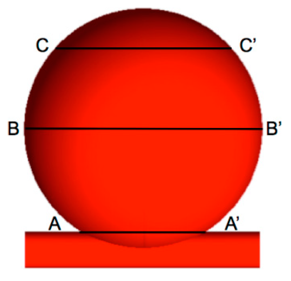
Figure 1. Idealized model of an idealized saccular giant brain aneurysm.
Fluids 07 00254 g001
Figure 2. Geometrical configuration [31] of the RS and the FD.
Fluids 07 00254 g002
Figure 3. Giant cerebral aneurysm divided into three different cross sections.
Fluids 07 00254 g003
Figure 4. Velocity contour at the mid plane (top) and the zoom view of the velocity contour (bottom) of the UA (left), RS (center), and FD (right) at peak systole.
Fluids 07 00254 g004
Figure 5. Velocity streamlines of the (left) UA, (center) RS, and (right) FD at peak systole.
Fluids 07 00254 g005
Figure 6. Velocity contour at the mid plane (top) and the zoom view of the velocity contour (bottom) of the UA (left), RS (center), and FD (right) at late diastole.
Fluids 07 00254 g006
Figure 7. Velocity streamlines of the (left) UA, (center) RS, and (right) FD at late diastole.
Fluids 07 00254 g007
Figure 8. Vorticity contour at different cross-sections of the (left) UA, (center) RS, and (right) FD at peak systole.
Fluids 07 00254 g008
Figure 9. Vorticity contour at different cross-sections of the (left) UA, (center) RS, and (right) FD at late diastole.
Fluids 07 00254 g009
Figure 10. Pressure contour at the mid plane of the UA (left), the RS (center), and FD (right) at peak systole.
Fluids 07 00254 g010
Figure 11. Pressure contour at the mid plane of the UA (left), RS (center), and FD (right) at late diastole.
Fluids 07 00254 g011
Figure 12. (a) Turnover time of the UA, RS, and FD at peak systole and late diastole and (b) average intra-aneurysmal velocity magnitude of the UA, RS, and FD at peak systole and late diastole.
Fluids 07 00254 g012
Table 1. WSS for the systolic cardiac flow.
UARSFD
A-A’13.2000 Pa2.6000 Pa (−80.3%)1.3000 Pa (−90.1%)
B-B’0.4500 Pa0.0660 Pa (−85.3%)0.0400 Pa (−91.1%)
C-C’0.1800 Pa0.0310 Pa (−82.7%)0.0015 Pa (−99.2%)
Table 2. WSS for the diastolic cardiac flow.
UARSFD
A-A’1.620 Pa0.8800 Pa (−45%)0.2400 Pa (−85%)
B-B’0.0380 Pa0.0043 Pa (−88.7%)0.0043 Pa (−88.7%)
C-C’0.0130 Pa0.0018 Pa (−86.1%)0.0001 Pa (−99.2%)
Publisher’s Note: MDPI stays neutral with regard to jurisdictional claims in published maps and institutional affiliations.

