Article

Optimization for Compact and High Output LED-Based Optical Wireless Power Transmission System

FIRST, IIR, Tokyo Institute of Technology, R2-39, 4259 Nagatsuta, Midori-ku, Yokohama 226-8503, Japan
*
Author to whom correspondence should be addressed.
Photonics 2022, 9(1), 14; https://doi.org/10.3390/photonics9010014
Submission received: 25 November 2021 / Revised: 23 December 2021 / Accepted: 24 December 2021 / Published: 28 December 2021

Abstract

:
Optical wireless power transmission (OWPT) is a technology that supplies energy remotely. Due to the great advantages of long transmission distances, high directionality, no electromagnetic interference noise, and loose safety regulations, light emitting diode (LED) based OWPT systems become appropriate candidates for powering various applications, especially for the Internet of things (IoT). In this paper, improved LED-OWPT systems are proposed based on a collimation scheme for optimizing the system dimension and output. In a single LED configuration, the system dimension is compressed by 46% while the high transmission efficiency is maintained. As for the LED-array system, the dimension is compressed by 56%, and the output is enhanced by 40%. In the experiment, a high electricity output of 532 mW is achieved at 1 m transmission distance. In addition, the effect of misalignment between LED and lens and the potential of long-distance transmission are clarified in the LED-array OWPT system.

1. Introduction

Wireless power transmission (WPT) is an important trending technology and has become a highly active research area because of the possible convenience for daily lives. WPT is a technology to transmit energy remotely from a power source to an electrical load [1]. This not only possibly reduces or eliminates the need for cables and batteries, but also provides sufficiently large power for achieving high functionality [2]. Wireless power transfer technologies can be categorized by transmission area into far and near fields [3]. Near-field WPT refers to the propagation distance within the wavelength of the transmitter antenna. The main near-field mechanisms are categorized according to the type of coupling technique, such as resonant coupling, inductive coupling, and capacitive coupling. However, near-field WPT is limited to short transmission distances, such as contact range. Furthermore, large dimension configurations and accurate alignment are required for large power and high efficiency [4]. On the other hand, far-field WPT technology relies on electromagnetic radiation, such as microwaves and optical beams, to enable long-distance power transfer [3]. As for microwave WPT, due to the diffraction effect, a large-sized phased-array antenna is necessary for increasing the directivity and transmission efficiency. Besides, high power electromagnetic radiation also results in the critical issue of electromagnetic interference (EMI) to the target and surrounding devices [5].
Therefore, optical wireless power transmission (OWPT) is a possible and promising candidate among WPT technologies. OWPT is defined as energy that transmits as a lightwave and is converted into electricity by an optical receiver at a remote position [6]. Due to the characteristics of the light beam and the applied devices, OWPT is the only WPT technology with the advantages of long transmission distances, high directivity, and no EMI [7]. Even compared with microwave WPT, OWPT with small dimension modules can maintain high efficiency over 100 m transmission distances due to the small diffraction effect [8].
OWPT can supply various applications, such as drones, electrical vehicles, and underwater robots. Recently, a collaboration of PowerLight technology and Ericsson company has demonstrated the world’s first 5G base station powered by OWPT [9]. Among all the applications, IoT is one of the most important targets, and more IoT terminals have been commercialized. Generally, most IoT terminals that require mini dimensions are difficult to integrate battery systems. Charging with a connector or replacing a battery is a heavy task. In addition, the energy supply method with cables for continuous operation is limited by the mobile situation and remote position. Fujikura Ltd. has developed a small-sized optic-electricity charging system based on the dye-sensitized solar cell (DSSC) for powering IoT terminals, but such a configuration limited load functionalities due to its μW-class output power [10]. Therefore, OWPT systems greatly fit the requirements of supplying IoT devices with relatively high outputs, especially for powering numerous IoT devices at the same time.
In recent years, laser-based WPTs have become an active research field and grown significantly [11,12]. However, lasers as the power source can cause critical issues on safety. Laser products should obey strict usage regulations. According to the IEC60825-2021 laser products classes, most of the laser products should ensure eye safety and provide under 5 mW radiation power [13]. On the other hand, a light emitting diode (LED) with a narrow spectrum can be considered as a proper option [14]. Due to the limited output power of LEDs, transmission efficiency is the most important factor in obtaining the highest possible output from a limited size solar cell for various applications. Although LEDs have difficulty with efficient power transmission due to their wide-angle emission characteristics, energy-efficient optical power delivery links have been suggested for non-laser light sources, such as LEDs by the 3-D beamforming technique [15].
As for the recent progress of LED-OWPT, a single LED system has been demonstrated with 224 mW electricity output in 2019 [16]. An aspheric condenser lens was applied close to the light source for decreasing the divergence, and an imaging lens with 100 mm aperture was placed 102 mm away from the LED and focused the beam on a 17 × 17 mm2 GaAs solar cell at 1 m transmission distance. The light source and lens system was integrated into a portable device with 116 × 116 × 132 mm3 dimensions; however, the distance between the light source and imaging lens was relatively long and enlarged the system dimension. In 2020, 380 mW electricity output was achieved at 1 m with a 3-LED array and a triple-layer lens system [17]. The first set of condenser lenses were still applied for converging the divergence beam from LEDs. After that, the beam was paralleled by the second set of condenser lenses and focused by a 110 mm aperture imaging lens. This system not only had a large dimension and complex structures, but also performed with low system efficiency.
In this paper, compact and high output LED-OWPT systems are proposed and optimized based on a collimation scheme as improved optical systems for IoT applications. A single LED collimation scheme shortens the length between the light source and lens system while maintaining a high system efficiency. A high output of 532 mW electricity at 1 m transmission distance is successfully demonstrated by a 3-LED-array module and a small-sized GaAs solar cell. In Section 2, the irradiation and LED performances are analyzed, and a compact single LED collimation scheme is designed. In Section 3, a high output LED-array OWPT system is also optimized. In Section 4, the displacement phenomenon of multiple irradiation spots and far distance transmission are discussed.

2. OWPT System Based on Single LED Collimation Scheme

In general, a basic OWPT system consists of three components: a light source, a lens system, and a light power receiver. The light source converts the input electricity into a lightwave and emits the optical power as the beam form. Due to the light diffraction properties, a lens system, composed of one or several lenses, is essential to improve the beam irradiation efficiency on the light receiver. The receiver is applied for converting the optical power to electricity power, which is supplied to the applications and IoT terminals. In addition, several functions should be prepared in an OWPT system, such as optical wireless communication, safety system, and recognition system of the mobile receivers. However, these functions are also under investigation and not covered in this paper. In this section, the LED-OWPT system based on a single LED collimation scheme is designed to compress the system dimension. Furthermore, the output effect factors in the LED collimation scheme are analyzed in order to propose a high output LED-OWPT system.

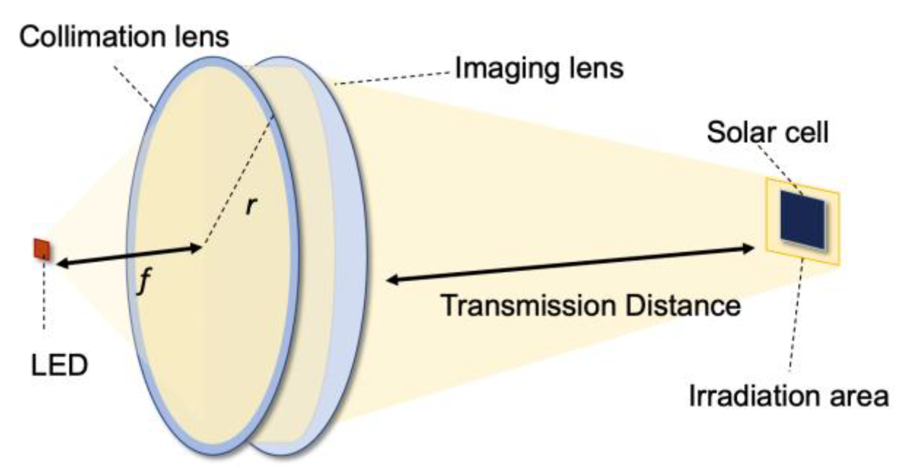
2.1. Lens System Based on Collimation Scheme

In this research, the size and the transmission distance of the target receiver are assumed to be fixed as the basic version in the LED-OWPT system. In the LED-OWPT system, designing a lens system is the most significant process for adjusting the irradiation spot and the transmission distance. An evaluation factor of lens system efficiency η is basically defined as:
η = I d S Φ
here, η is the lens system efficiency, Φ is the radiant flux of the LED with the unit of watt, and I is the irradiance on the target with the unit of W·m−2. dS is the differential area of irradiation spot with the unit of m2 [18].
Even a high directional LED also possesses a divergence angle in contrast with a semiconductor laser [19]. Only one lens is difficult to constrain the divergence within a small angle. It causes beam leakage during propagation and decreases the power transmission efficiency. Therefore, a collimation scheme based on double lenses is proposed and shown in Figure 1.
The lens system consists of one collimation lens and one imaging lens. This lens system is simple because OWPT uses monochromatic light and does not require high-resolution imaging like photographs. An LED chip as a light source is placed at the front focal point of the collimation lens. Through this lens, the divergence beam from the LED is in alignment. By applying an imaging lens, this collimation beam can be focused on the light receiver at a remote position.
In the LED-OWPT system, the lens system is designed for adjusting the transmission distance and irradiation spot size on the fixed target. The analysis of transmission distance will be discussed in Section 4.2. As for the irradiation spot size, a horizontal magnification is introduced for evaluation in an optical system. The horizontal magnification β is defined as the ratio of the image height to the object height. An optical path of a typical double lenses system in atmospheric media is shown in Figure 2.
In this figure, l and l   are the object distance and the imaging distance, respectively. f and f are the front focal length and the back focal length of the lens. d is the distance between the two lenses, and the lens thickness is ignored. Subscript shows the lens number.
From the Gaussian formula [20],
f 1 ' l 1 ' + f 1 l 1 = 1
For Lens1, its horizontal magnification can be described by substituting l 1 '
β 1 = l 1 ' l 1 = f 1 ' l 1 f 1
For Lens2, the similar derivation is applied by substituting l 1 '
β 2 = l 2 ' l 2 = l 2 ' d l 1 ' = l 2 ' ( l 1 f 1 ) d ( l 1 f 1 ) f 1 ' l 1
The total horizontal magnification of a double lenses system can be expressed as:
β = β 1 β 2 = l 2 ' f 1 ' d ( l 1 f 1 ) f 1 ' l 1
In a collimation scheme, the focal length of the collimation lens f 1 is equal to the object distance l 1 , so the horizontal magnification can be simplified as:
β = l 2 ' f 1
here, l 2 ' is the system image distance and f 1 is the front focal length of the collimation lens. From this formula, in the collimation scheme with the fixed image distance, the irradiation size is inversely proportional to the focal length of the collimation lens. From the viewpoint of the dimension limited applications, especially the IoT terminals, the areas of power receivers are required to be sufficiently small; therefore, a longer focal length of a collimation lens is necessary.

2.2. Selection of Light Source and Receiver

An LED with a sufficiently narrow spectrum can be roughly regarded as a monochromatic light source for OWPT [21]. A GaAs solar cell is considered as a high-performance and purchasable light receiver [22]. Due to 1.43 eV bandgap energy of GaAs, the suitable wavelengths to achieve high photon energy should be near-infrared from 800 nm to 870 nm [23]. This combination has been experimented with 41% photoelectric conversion efficiency [16], and it is regarded as a relatively high result among the commercially available solar cells.
Applying a higher power LED is generally considered as a conventional method to increase the system output; however, with the dimension restricted light receiver, the irradiation result is opposite to this expectation. Regarding LED chips, the radiant flux, chip dimensions, wavelength, and divergence angle depend on different chip models. The radiant flux and chip dimensions are the most important effect factors related to the irradiation power and size. Several commercial LED chips of OSRAM Co. are listed as light source candidates with the wavelength of the near-infrared range [24,25,26,27]. A relatively small 17 × 17 mm2 solar cell is assumed in this section. The LED parameters and the simulated irradiation performances via the collimation scheme are shown in Table 1. The numerical simulations are carried out by ZEMAX software. The device model parameters of lenses are prepared by the authors’ group.
The total irradiation shown in the table is the entire light power on an infinity area at 1 m distance. Although the radiant flux of the LED SFH4703AS is 1.04 W and the smallest value among these chips, it performs the largest surface irradiation on the 17 × 17 mm2 size solar cell. As a larger emission area of LED is the key to achieving a higher radiant due to saturation characteristics of the emission efficiency under high current density injection, it also leads to a larger irradiation spot. When the irradiation area exceeds the size limited receiver, it can cause the irradiation power loss and decrease the system output. In the LED assembly, the radiant flux of the LED is positively correlated to its chip area. Therefore, a small chip dimension LED with high radiant exitance is more appropriate for a small area receiver in the OWPT system.
On the other hand, the LED divergence angle also affects the irradiation result. In the collimation scheme and under the same lens aperture condition, a larger divergence LED enhances the beam leakage more critically. The numerical aperture (NA) requires the lens aperture to be smaller than its focal length. When the extremely large divergence light source, such as LED SHF4716AS, is applied at the front focal point of an NA = 1 lens, over 90° radiant beams are not through the lens and not in collimation, these parts are the beam leakage and cause a decline in system efficiency. Thus, LED SFH4703AS with 0.75 × 0.75 mm2 chip dimensions, 1.04 W radiant flux, and an 80° divergence angle is selected as a proper light source.

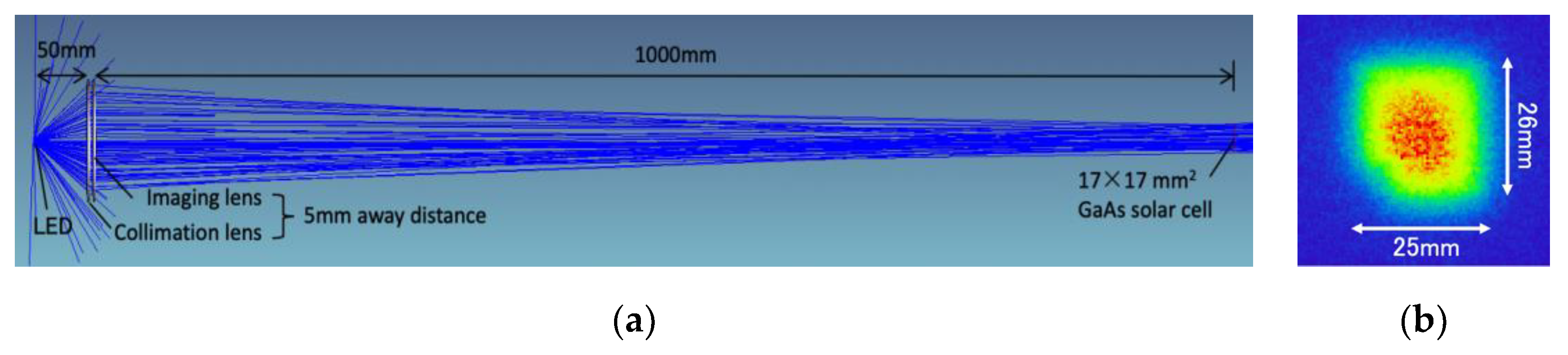
2.3. Design of Single LED Collimation Scheme

From the above discussion, an OWPT system based on a single LED collimation scheme is proposed. A lens with 100 mm aperture diameter and 50 mm focal length is applied as the collimation lens. The other lens with 100 mm aperture diameter and 1000 mm focal length is used as an imaging lens. Normal glass convex lenses cannot be manufactured with such large NA; therefore, Fresnel lenses are chosen as the typical collimation lenses which fit the NA = 1 requirement [28]. In addition, due to the plastic material instead of the glass, a Fresnel lens is extremely advanced in its light weight and low thickness properties. As for the light source and receiver, a near-infrared LED (OSRAM SFH4703AS, 1.04 W, 810 nm, 80°) is applied at the front focal point of the collimation lens and a 17 × 17 mm2 GaAs solar cell is configured at 1 m from the imaging lens. Due to the collimation beam after passing the collimation lens, the distance between the two lenses can be any value. From the viewpoint of the compact size and practical condition, the distance between the two lenses is set as 5 mm. The simulation configuration and irradiation spot by ZEMAX software is shown in Figure 3.
As for the simulation result, the lens system efficiency is 74.5%. The irradiation spot size at 1 m is 25.4 × 26.6 mm2 and the surface irradiation on the 17 × 17 mm2 solar cell is 352 mW. In the former single LED scheme through double convergences, the light source set thickness from the LED to the imaging lens is 102 mm [16]. In the collimation scheme, the imaging lens can be extremely closed to the collimation lens, so the light source set thickness only depends on the collimation lens focal length. Therefore, the value is reduced from 102 mm to 55 mm and compressed by 46%. The collimation scheme can significantly reduce the dimensions of the light source set while maintaining a fairly high lens system efficiency.

3. LED-Array System for Increasing Output

As mentioned in Section 2.2, using a large radiation LED chip is not a proper method for increasing the output of the LED-OWPT system. The importance is to increase the output while retaining a small irradiation area. Therefore, a method of arraying LEDs based on a collimation scheme is investigated to improve the output performance. The configuration of an LED-array OWPT system is shown in Figure 4. Several LEDs are arranged to form the light source and are still applied at the front focal points of the collimation lenses. Since beams from all LEDs are parallelly emitted on the imaging lens, only one imaging lens can rearrange the intensity distribution [29]. Thus, the collimation scheme can overlap all irradiation spots from different LEDs. In theory, the spot size is the same as a single LED configuration. Furthermore, the total irradiation power is simply proportional to the number of applied LEDs.

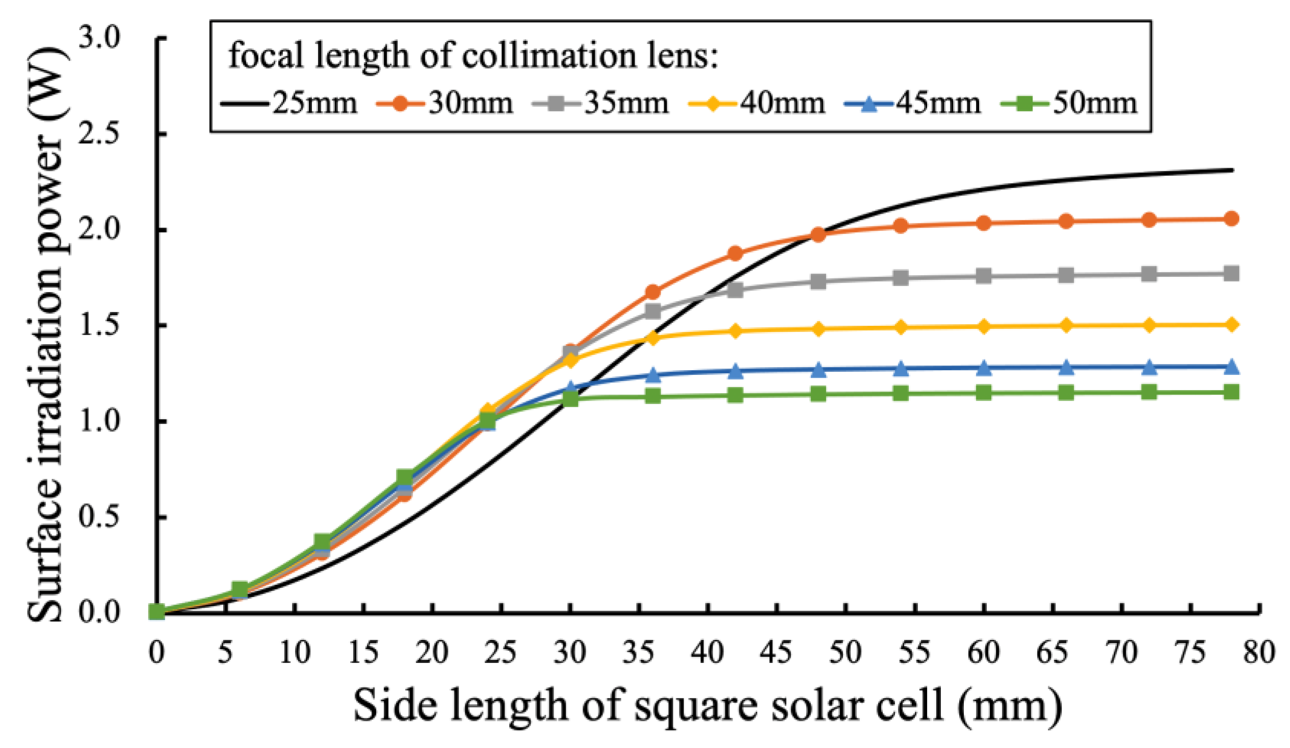
3.1. Analysis of Irradiation Power in the Collimation Scheme

In the collimation scheme, a collimation lens with a longer focal length causes beam leakage more critically under the same lens aperture conditions. On the other hand, a shorter focal length increases the irradiation spot size and leads to power loss. Thus, the surface irradiation and the focal length of the collimation lens are in a tradeoff relationship. For exploring the optimal parameters of the collimation lens, the relationship between the receiver surface irradiation and focal lengths of collimation lenses is analyzed by the simulation. The number of LEDs is assumed to be three, and the same near-infrared LEDs (OSRAM SFH4703AS) are arranged as an equilateral triangle shape with a 50 mm side length. The aperture and focal length of one imaging lens remains as 110 mm and 1000 mm, and the transmission distance is equal to the imaging lens focal length. In the optical simulation, the LED model document is provided by the simulation library of the company OSRAM. The focal length, aperture, and placement of each lens are inserted in the non-sequential mode. Three collimation lenses’ aperture diameters are maintained as 50 mm, and their focal lengths are changed from 25 mm to 50 mm. The surface irradiation results on variable receiver areas are organized and shown in Figure 5.
In Figure 5, the horizontal axis is the side length of the irradiation spot. Each curve shows rise and then saturated tendency. It indicates that the surface irradiation is boosted with the increment of receiver size. When the solar cell area is larger than irradiation spot, the surface irradiation is optimal and not increased anymore. The spot sizes and the total irradiation powers are shown in Table 2. Total irradiations in the table correspond to the saturated irradiation power in Figure 5. Among all the curves, while increasing the focal length of the collimation lens, the surface irradiation power at the saturated condition is decreased. Although f = 50 mm collimation lens has the smallest irradiation spot and the optimal irradiation when the side length of the solar cell is less than 25 mm, its surface irradiation power is limited under 1.2 W. When the side length of the light receiver is less than 50 mm, f = 30 mm collimation lens is the best candidate. However, for obtaining the largest output, f = 25 mm performs the largest surface irradiation power when the solar cell area is larger than 50 × 50 mm2. Thus, in the following discussion, collimation lenses (d = 50 mm, f = 25 mm) are considered for composing the high-performance LED-OWPT system.

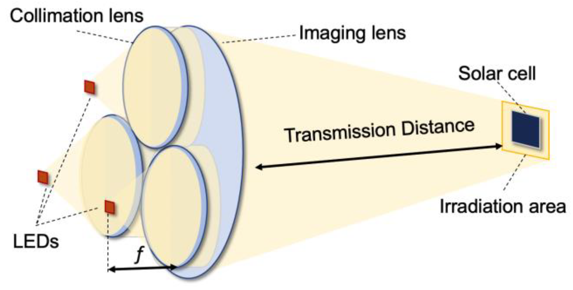
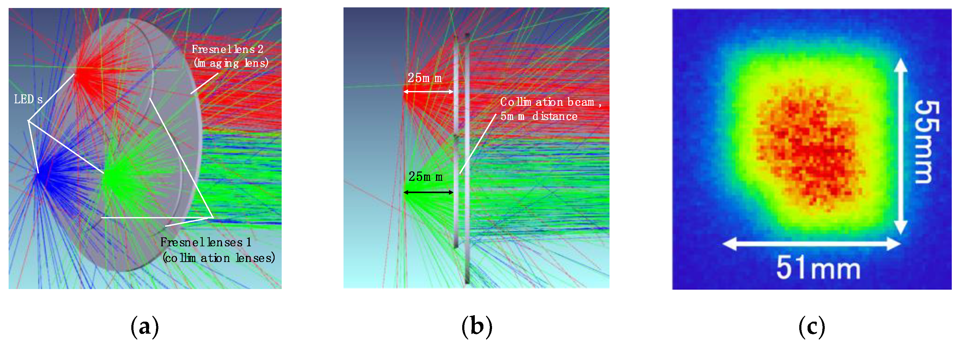
3.2. Design of High Output LED-OWPT System

In the former report, a 3-LED-array OWPT system was experimented with a 380 mW electricity output at 1 m transmission distance [17]. To improve the electricity output of the LED-OWPT system, a novel lens system is designed based on the above discussion. The light source is composed of three same LEDs (OSRAM SFH4703AS), three collimation lenses (50 mm diameter, 25 mm focal length), and one imaging lens (110 mm diameter, 1000 mm focal length) to form the lens system. All lenses use Fresnel lenses, and each LED is applied at the front focal point of the collimation lens, respectively. The simulated configuration by ZEMAX software and the irradiation spot at 1 m are shown in Figure 6. Based on Figure 5, the surface irradiation performance on the former 17 × 17 mm2 area is under a 0.7 W level and relatively small. In this design, a 50 × 50 mm2 GaAs solar cell as the receiver is applied at a 1 m distance from the imaging lens. With a 50 × 50 mm2 area receiver, the surface irradiation of the selected lenses combination achieves a 2 W class and is closed to saturation. This 50 × 50 mm2 area is also regarded as a small dimension and acceptable for most high-power required IoT terminals.
From the simulation shown in Figure 6c, the irradiation spot size is 51 × 55 mm2. The result and comparison with the former system are shown in Table 3. Compared with the former 3-LED-array system, which used glass convex lenses [17], the lens efficiency of the proposed system is increased to 63%. The lenses weight is abundantly decreased by 84% from 438 g to 72 g. The light source set distance can be compressed to 35 mm and is decreased by 56% from the former system. Both parameters show that the optimized system has great improvement on portability and small dimensions.

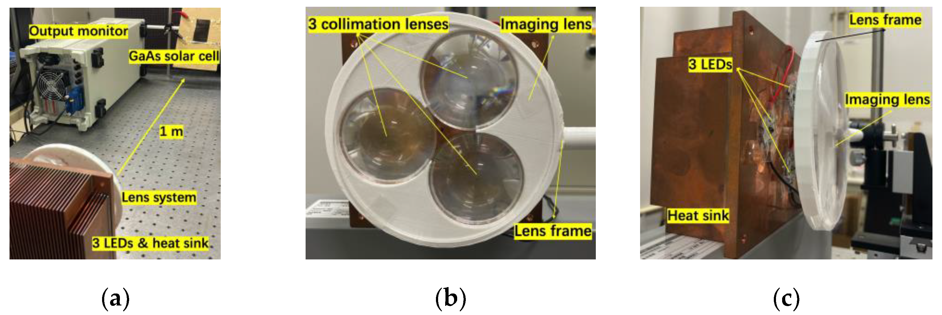
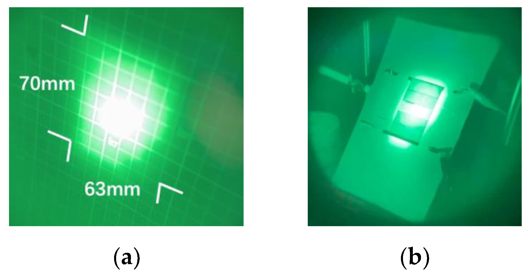
3.3. Experimental Setup and Measured Results

Figure 7 shows the experimental setup and lens combination for a high output LED array system. The basic experimental setup was the same as designed. Three same LEDs (OSRAM, SFH4703AS) with a series circuit were assembled on a heat sink. Three Fresnel lenses (NTKJ, CF25) were applied as collimation lenses. One Fresnel lens (NTKJ, CF1000) was used as an imaging lens. To obtain a 1 W light output from each LED, the applied voltage and current of the LED-array were 10.6 V and 1.0 A. The 5-series connected GaAs solar cell (Advanced Technology Institute, LLC, Virginia Beach, VA, USA) was applied as the light receiver at 1 m after the imaging lens. In the experiment, up to 532.4 mW electricity output was achieved. The optimal operating voltage and current were 4.7 V and 114.6 mA, respectively. All the results were measured by an output monitor (ADCMT, 6243 DC monitor).
The irradiation spot in the experiment was observed by an infrared viewer (Electrophysics, ElectroViewer7215). Figure 8 shows the experimental irradiation spot with 70 × 63 mm2. This irradiation size was larger than the designed size and the reason is discussed in Section 4.1. Currently, a 50 × 50 mm2 GaAs solar cell, which is the ideal size in the simulation, is difficult to purchase and was not commercially available. The 5-series connected GaAs solar cell had a size of 50 × 85 mm2. Since partial irradiation on a series-connected solar cell module significantly reduces the conversion efficiency [30], rotating the solar cell to obtain an appropriate size receiver is one of the possible solutions in a tentative experiment. Therefore, the 5-series GaAs solar cell was rotated at a 40° angle in the vertical direction. With the 40° slanted solar cell, the vertical projection area was 50 × 65 mm2, and the irradiation spot was slightly larger than the solar cell size.
The detailed results are shown in Table 4 compared with the former reported triple-layer lenses system [17]. As for the experimental result, the irradiation power on the solar cell of the improved system was 1.5 times. The electricity output was vastly boosted by 40% as well. Under the same condition of a 50 × 65 mm2 irradiation area, 532 mW electricity output of this LED-OWPT system was approached to the power under sunlight of AM1.5G (1 kW/m2) with 18% conversion efficiency [31]. In addition, as for the commercial DSSC-based IoT power supply production (FDSC-FSC5FGC, Fujikura Co., Tokyo, Japan), its 8 h of irradiation under a household LED 200 Lx condition was the same as 5 s of irradiation of this proposed LED-OWPT system [10]. Therefore, the achieved high output power of the proposed system was possibly to supply various IoT terminals.

4. Discussion of Experimental Results

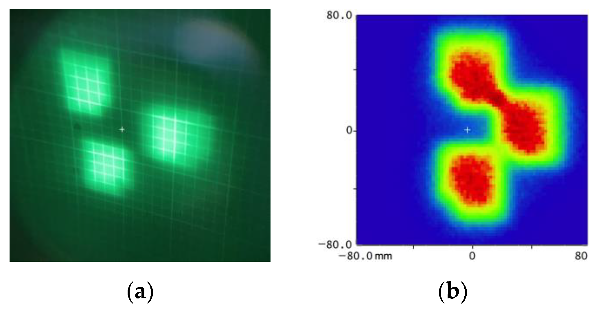
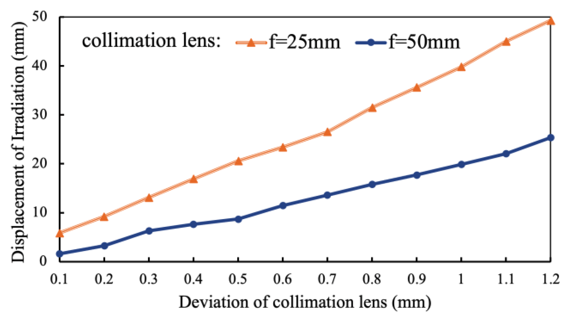
4.1. Displacement in LED-Array System

As the statement in Section 2.2, the theoretical irradiation spot should be overlapped as a 51 × 55 mm2 dimension. In the experiment, however, the irradiation size was larger than the simulation result. This was caused by the lens position deviation from the LED position. As shown in Figure 9a, if each lens position has an intentional 1 mm deviation from the center of the LED position, each irradiation spot will have a 40 ± 10 mm position deviation, and the irradiation spots of each LED will be separated. Such a displacement phenomenon enlarges the irradiation area and disperses the irradiation power.
This displacement phenomenon is more apparent for the collimation lens with a short focal length. In the verification, the central place of a collimation lens deviated from 0.1 mm to 1.2 mm. Two sets of collimation lens focal lengths were applied in the simulation; the coordinate value differences of the irradiation spot are the displacement results and shown in Figure 10. In the LED-array collimation scheme, a 0.1 mm lens position deviation of an f = 25 mm collimation lens could cause a 4 mm displacement on the final irradiation. Contrastively, the same 0.1 mm deviation of an f = 50 mm collimation lens could cause a 2 mm displacement.

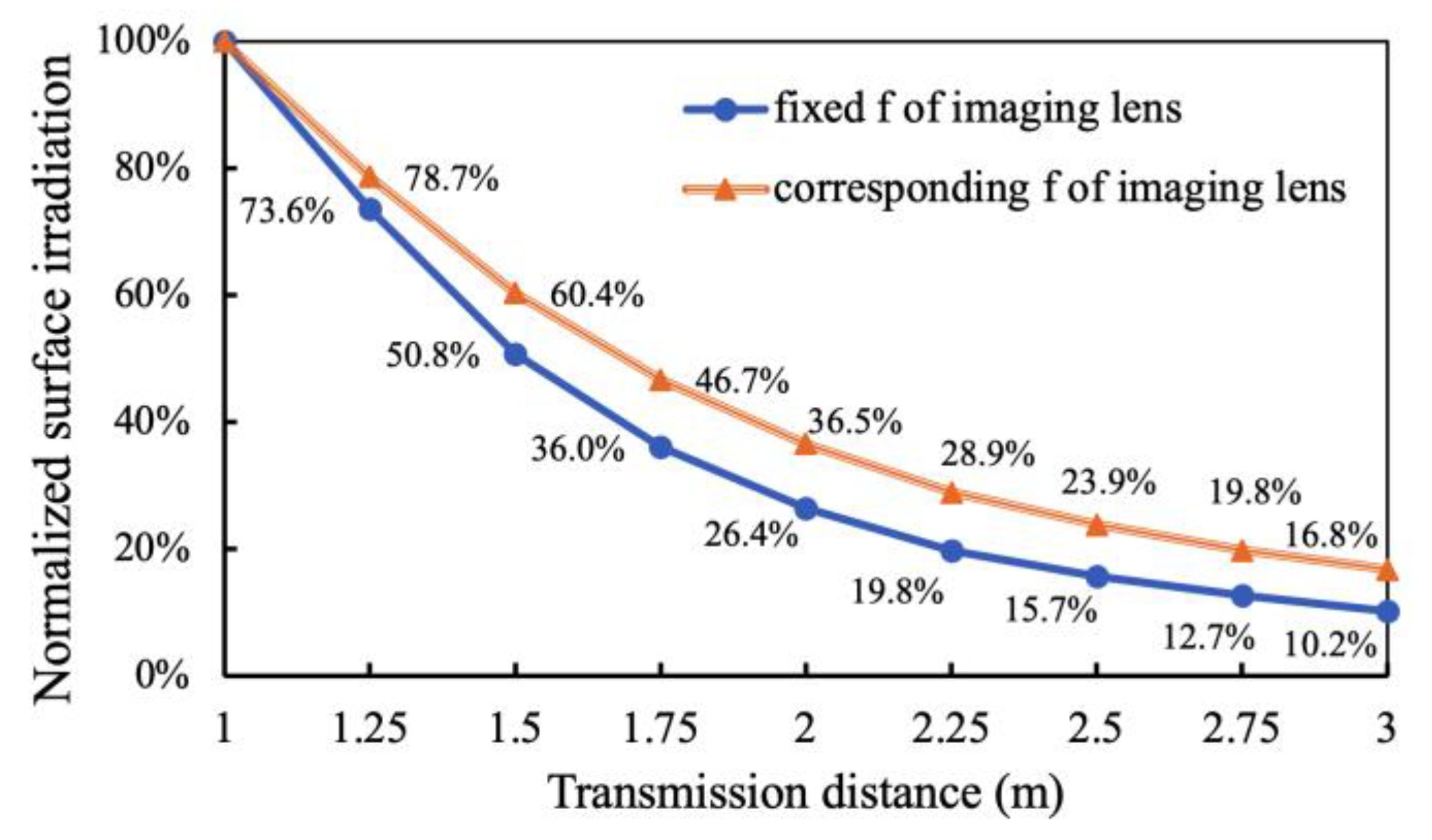
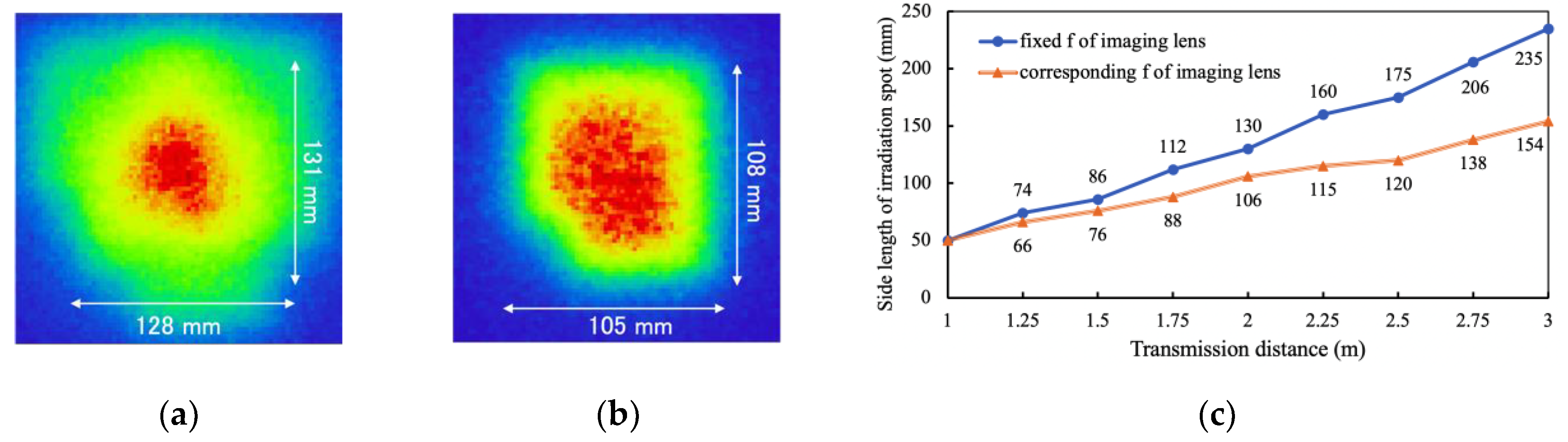
4.2. Possibility Discussion of Longer Distance Transmission

In this paper, a system was designed to obtain optimal power at a 1 m transmission distance with an f = 1 m imaging lens. With a fixed focal length of the imaging lens, a tolerance range to the different target distance was proved with a small performance deterioration [32]. On the other hand, applying different focal lengths of the imaging lens was another viable option for different transmission distances. In the case of the collimation scheme, only replacing the imaging lens with a longer focal length lens could realize the long-distance transmission. The difference between fixed and variable focal lengths of imaging lenses for longer transmission distance was explored. In a 3-LED-array configuration, three collimation lenses (d = 50 mm, f = 25 mm), an imaging lens (d = 110 mm), and a 50 × 50 mm2 solar cell were applied. The comparison results are shown in Figure 11. The blue curve with round markers shows the normalized surface irradiation by a fixed f = 1 m imaging lens. The orange curve with triangle markers shows the performance of the imaging lens f = transmission distance condition.
In Figure 11, because the irradiation spot becomes larger than the solar cell area, in the case of longer transmission distance, even with the imaging lens focal length correspondingly equal to the transmission distance, there is still a large attenuation of surface irradiation. The simulated irradiation spots at a 2 m distance are shown in Figure 12a,b for focal lengths of 1 m and 2 m, respectively. Due to the fixed f = 1 m imaging lens, Figure 12a shows an unfocused status, and its area is roughly 1.4 times larger than the focused status in Figure 12b. The relationship between transmission distance and the side length of irradiation spot is shown in Figure 12c. From a 1 m to 3 m transmission distance, the irradiation area enhanced 22 times with a fixed f = 1 m imaging lens and 9 times with the corresponding focal length of the imaging lens. Both methods caused critical power loss and were not possible to supply power by a 50 × 50 mm2 solar cell. In order to realize the high level of output, the receiver size should be extended when the transmission distance is over 1.5 m. For example, by applying a 100 × 100 mm2 solar cell, a 1.55 W surface irradiation will be achieved with a fixed f = 1 m imaging lens at 2 m, and 0.72 W will be obtained at 3 m.
As for the method of variable imaging lens focal length, applying a zoom lens is possible to provide flexible focal length. However, in the system based on the collimation scheme, for obtaining a small size irradiation spot, the collimation lens should be placed at a certain distance from the LEDs; accordingly, the lens aperture should be larger for decreasing the beam leakage. In this research, the imaging lens diameter was a 100 mm level. As for the zoom lens, a laser-based OWPT system has been demonstrated with a liquid lens for controlling the transmission distance by electric intensity without changing the lens position [33]. However, currently, a liquid lens is difficult to manufacture as a 100 mm level aperture [34], so applying the liquid lens is inapposite for a high-performance LED-OWPT system based on a collimation scheme.

5. Conclusions

In this paper, the improved LED-OWPT systems were designed with a small dimension and high output; novel lens combinations were proposed based on a collimation scheme. The system imaging distance and focal length of the collimation lens were analyzed as the effect factors of irradiation size in the collimation scheme. It is also provided that the performance of a higher radiant flux LED is not always apparent, especially for a small-sized receiver. Due to the large divergence of LED light source, the NA = 1 collimation lens can achieve the optimal output against the beam leakage. As a result, the system dimensions based on the collimation scheme can be compressed by around 50% while maintaining a high lens system efficiency. In the experiment of the improved LED-array system, 532 mW electricity power was achieved at a 1 m transmission distance. In addition, the displacement phenomenon and the possibility of long-distance transmission were analyzed in the improved LED-array OWPT. The displacement phenomenon of the irradiation spot was more critical to the shorter focal length collimation lens system; a 1 mm lens deviation of f = 25 mm collimation lens caused a 40 mm displacement. In the case of long-distance transmission, whether the imaging lens focal length is 1 m or longer, the enhanced irradiation area caused power loss on a 50 × 50 mm2 solar cell. The receiver area should be extended to achieve the same high-level output. As a result of this research, a safe, compact, highly efficient, and high-power LED-based OWPT configuration has been clarified. This result is operative for realizing wireless power transmission of several hundred mW class applications, such as IoT terminals.

Author Contributions

Conceptualization and methodology, M.Z. and T.M.; software, experiment, validation, and data curation, M.Z.; formal analysis, M.Z. and T.M.; writing—original draft preparation, M.Z.; writing—review and editing, T.M.; supervision, administration, and funding acquisition, T.M. All authors have read and agreed to the published version of the manuscript.

Funding

This research was funded by Tsurugi-Photonics Foundation (No. 20210401) and Fujikura Foundation (No. 18-024).

Acknowledgments

The authors thank Yuhuan Zhou for the discussion of optical system design and simulation. We also thank members in the T. Miyamoto Lab for experiment assistance.

Conflicts of Interest

The authors declare no conflict of interest.

References

  1. Shidujaman, M.; Samani, H.; Arif, M. Wireless power transmission trends. In Proceedings of the 2014 International Conference on Informatics, Electronics & Vision (ICIEV), Dhaka, Bangladesh, 23–24 May 2014; pp. 1–6. [Google Scholar]
  2. Sumi, F.; Dutta, L.; Sarker, F. Future with wireless power transfer technology. J. Electr. Electron. Syst. 2018, 7, 2332-0796. [Google Scholar]
  3. Moon, J. High-frequency capacitive wireless power transfer technologies. J. Power Electron. 2021, 21, 279. [Google Scholar] [CrossRef]
  4. Jawad, A.M.; Nordin, R.; Gharghan, S.K.; Jawad, H.M.; Ismail, M. Opportunities and challenges for near-field wireless power transfer: A review. Energies 2017, 10, 1022. [Google Scholar] [CrossRef]
  5. Lenaerts, B.; Puers, R. Omnidirectional Inductive Powering for Biomedical Implants; Springer Science & Business Media: Dordrecht, The Netherlands, 2008; pp. 119–121. [Google Scholar]
  6. Miyamoto, T. Optical wireless power transmission using VCSELs. In Semiconductor Lasers and Laser Dynamics VIII; SPIE Photonics Europe: Strasbourg, France, 2018; Volume 10682. [Google Scholar]
  7. Miyamoto, T. Undersea optical wireless power transmission method using light beam, features, technologies, and issues. In Proceedings of the IEICE Technical Report, Online, 25–27 November 2020. IEICE-120. [Google Scholar]
  8. Putra, A.W.S.; Kato, H.; Adinanta, H.; Maruyama, T. Optical wireless power transmission to moving object using galvano mirror. In Proceedings of the Free-Space Laser Communications XXXII, San Francisco, CA, USA, 1–6 February 2020; Volume 11272, pp. 314–322. [Google Scholar]
  9. Ericsson and Powerlight Base Station Wireless Charging. Available online: https://www.ericsson.com/en/news/2021/10/ericsson-and-powerlight-achieve-base-station-wireless-charging-breakthrough (accessed on 19 October 2021).
  10. Fujikura DSSCs Toward a World Without Need for Battery Replacement. Available online: https://dsc.fujikura.jp/en/ (accessed on 6 October 2021).
  11. Duncan, K.J. Laser Based Power Transmission: Component selection and laser hazard analysis. In Proceedings of the IEEE PELS Workshop on Emerging Technologies: Wireless Power Transfer (WoW), Knoxville, TN, USA, 4–6 October 2016; pp. 100–103. [Google Scholar]
  12. Katsuta, Y.; Miyamoto, T. Design and Experimental Characterization of Optical Wireless Power Transmission Using GaAs Solar Cell and Series-Connected High-Power Vertical Cavity Surface Emitting Laser Array. Jpn. J. Appl. Phys. 2018, 57, 08PD01. [Google Scholar] [CrossRef] [Green Version]
  13. IEC 60825:2021 SER, International Electrotechnical Commission. Available online: https://webstore.iec.ch/publication/62424 (accessed on 6 October 2021).
  14. Zhou, Y.; Miyamoto, T. Optimized LED-based optical wireless power transmission system configuration for Compact IoT. In Proceedings of the 24th Microoptics Conference (MOC), Toyama, Japan, 17–20 November 2019; pp. 154–155. [Google Scholar]
  15. Marraccini, P.; Riza, N. Smart Multiple-Mode Indoor Optical Wireless Design and Multimode Light Source Smart Energy-Efficient Links. Opt. Eng. 2013, 52, 055001. [Google Scholar] [CrossRef]
  16. Zhou, Y.; Miyamoto, T. 200 mW-class LED-based optical wireless power transmission for compact IoT. Jpn. J. Appl. Phys. 2019, 58, SJJC04. [Google Scholar] [CrossRef]
  17. Zhou, Y.; Miyamoto, T. 400 MW Class High Output Power from LED-Array Optical Wireless Power Transmission System for Compact IoT. IEICE Electron. Express 2020, 18, 20200405. [Google Scholar] [CrossRef]
  18. Boyd, R. Radiometry and the Detection of Optical Radiation; John Wiley and Sons: New York, NY, USA, 1983; pp. 109–110. [Google Scholar]
  19. Uchiyama, N.; Yamada, H. Proposal and Demonstration of LED optical wireless power-transmission systems for battery-operated small electronic devices. Jpn. J. Appl. Phys. 2020, 59, 124501. [Google Scholar] [CrossRef]
  20. Born, M.; Wolf, E. Principles of Optics: Electromagnetic Theory of Propagation, Interference and Diffraction of Light, 7th ed.; CUP: Cambridge, UK, 2000; pp. 167–170. [Google Scholar]
  21. Optiwave. Available online: https://optiwave.com/ (accessed on 21 October 2021).
  22. Carr, W.N. Characteristics of a GaAs spontaneous infrared source with 40 percent efficiency. IEEE Trans. Electron. Devices 1965, 12, 531–535. [Google Scholar] [CrossRef]
  23. Andreev, V.; Khvostikov, V.; Kalinovsky, V.; Lantratov, V.; Grilikhes, V.; Rumyantsev, V.; Shvarts, M.; Fokanov, V.; Pavlov, A. High current density GaAs and GaSb photovoltaic cells for laser power beaming. In Proceedings of the 3rd World Conference on Photovoltaic Energy Conversion, Osaka, Japan, 11–18 May 2003; Volume 1, pp. 761–764. [Google Scholar]
  24. SFH 4703AS. Available online: https://www.osram.com/ecat/OSLON%C2%AE%20Black%20SFH%204703AS/com/en/ (accessed on 21 October 2021).
  25. SFH 4715AS. Available online: https://www.osram.com/ecat/OSLON%C2%AE%20Black%20SFH%204715AS/com/en/ (accessed on 21 October 2021).
  26. SFH 4716AS. Available online: https://www.osram.com/ecat/OSLON%C2%AE%20Black%20SFH%204716AS/com/en/ (accessed on 21 October 2021).
  27. SFH 4717AS. Available online: https://www.osram.com/ecat/OSLON%C2%AE%20Black%20SFH%204717AS%20A01/com/en/ (accessed on 21 October 2021).
  28. Andersen, G.; Knize, R.J. A high resolution, holographically corrected microscope with a Fresnel lens objective at large working distances. Opt. Express 1998, 2, 546–551. [Google Scholar] [CrossRef]
  29. Zhou, Y.; Zhao, M.; Miyamoto, T. Optimization of dimension and output power of the portable LED-based OWPT system for compact IoT. In Proceedings of the 3rd Optical Wireless and Fiber Power Transmission Conference (OWPT 2021), Online, 19–22 April 2021; p. OWPT-2-04. [Google Scholar]
  30. Tang, J.; Matsunaga, K.; Miyamoto, T. Numerical analysis of power generation characteristics in beam irradiation control of indoor OWPT system. Opt. Rev. 2020, 27, 170–176. [Google Scholar] [CrossRef]
  31. ASTM G173-03(2008); Standard Tables for Reference Solar Spectral Irradiances. Available online: https://webstore.ansi.org/standards/astm/astmg173032008 (accessed on 21 October 2021).
  32. Zhou, Y.; Miyamoto, T. Design of LED-based optical wireless power transmission for long distance operation and increased output power. In Proceedings of the 2nd Optical Wireless and Fiber Power Transmission Conference (OWPT 2020), Online, 21–23 April 2020; p. OWPT-3-04. [Google Scholar]
  33. Toyama, Y.; Miyamoto, T. Beam control using liquid lens for optical wireless power transmission system. In Proceedings of the 2nd Optical Wireless and Fiber Power Transmission Conference (OWPT 2020), Online, 21–23 April 2020; p. OWPT-P-10. [Google Scholar]
  34. Hasan, N.; Kim, H.; Mastrangelo, C. Large aperture tunable-focus liquid lens using shape memory alloy spring. Opt. Express 2016, 24, 13334–13342. [Google Scholar] [CrossRef] [PubMed]
Figure 1. Collimation scheme in a single LED OWPT system.
Photonics 09 00014 g001
Figure 2. Optical path of a double lenses system.
Photonics 09 00014 g002
Figure 3. (a) Simulation model of a Fresnel lens collimation system; (b) Simulated irradiation spot.
Photonics 09 00014 g003
Figure 4. Collimation scheme in an LED-array OWPT system.
Photonics 09 00014 g004
Figure 5. Simulated irradiation power at 1 m with different focal lengths of collimation lenses.
Photonics 09 00014 g005
Figure 6. Simulation of the improved LED-OWPT system: (a) view from LED chip, (b) view from the side; and (c) irradiation spot at 1 m.
Photonics 09 00014 g006
Figure 7. (a) Experiment setup; (b) lens combination; and (c) view from the side of the light source.
Photonics 09 00014 g007
Figure 8. (a) Experimental irradiation spot; (b) 5-series solar cell with 40° rotation.
Photonics 09 00014 g008
Figure 9. (a) Displacement by lens position deviation in the experiment (grid board scale: 10 mm); (b) simulation of each lens position with a 1 mm deviation.
Photonics 09 00014 g009
Figure 10. Displacement of irradiation place caused by lens deviation.
Photonics 09 00014 g010
Figure 11. Longer distance transmission performance with a 50 × 50 mm2 size solar cell.
Photonics 09 00014 g011
Figure 12. Simulated irradiation spot in long-distance transmission: (a) f = 1 m imaging lens at 2 m; (b) f = 2 m imaging lens at 2 m; (c) simulated irradiation spot side length with fixed and corresponding focal length of imaging lens. Side length is measured from the range where the light intensity is 20% or more of the peak intensity.
Photonics 09 00014 g012
Table 1. Commercial LED parameters and their simulated irradiation performances.
SFH4703AS
[24]
SFH4715AS
[25]
SFH4716AS
[26]
SFH4717AS
[27]
Chip dimension (mm2)0.75 × 0.751 × 11 × 11 × 1
Radiant flux (W)1.041.531.531.34
Divergence angle (°)808015050
Total irradiation (mW)7741110625946
Surface 1 irradiation (mW)352306230189
1 17 × 17 mm2 size solar cell.
Table 2. Irradiation performances by different focal lengths of collimation lenses.
Focal Length (mm)Total 2 Irradiations (W)Spot Size (mm2)
252.3151 × 55
302.0546 × 48
351.7739 × 41
401.5131 × 33
451.2928 × 30
501.1527 × 28
2 80 × 80 mm2 area.
Table 3. Simulated efficiency at 1 m and measured parameters of a 3-LED-OWPT system.
Lens System EfficiencyLenses Weight (g) Lens Set Distance (mm)
Former system [17]57.2 ± 2%438 ± 1080 ± 5
Improved system63.2 ± 2%72 ± 1035 ± 5
Table 4. Simulation (sim.) and experimental results (exp.) of the former and improved systems.
Lens System EfficiencyIrradiation Size (mm2)Irradiation on Solar Cell (mW)Electricity Output (mW)
Former system [17]Sim.57.2%38 × 411784N/A
Exp.30.8%35 × 54960380
Improved systemSim.63.2%51 × 551971N/A
Exp.47.1%63 × 701470532
Publisher’s Note: MDPI stays neutral with regard to jurisdictional claims in published maps and institutional affiliations.

