Article

Investigation of Crosstalk between Data Signals and Feed Light in Power-over-Fiber

Graduate School of Informatics and Engineering, University of Electro-Communications, 1-5-1 Chofugaoka, Chofu 182-8585, Tokyo, Japan
*
Author to whom correspondence should be addressed.
Photonics 2022, 9(6), 369; https://doi.org/10.3390/photonics9060369
Submission received: 6 April 2022 / Revised: 21 May 2022 / Accepted: 23 May 2022 / Published: 25 May 2022

Abstract

:
In power-over-fiber systems, simultaneous data signals and power transmission using a single optical fiber is an attractive step towards simplifying the systems. However, when simultaneously transmitting data signals and feed light in a single core, the transmission quality of the data signal degrades owing to the crosstalk based on the characteristics of the feed light source. In this study, we investigate and evaluate the crosstalk between the data signal and high-power feed light in a power-over-fiber system. To observe the effect of the crosstalk more clearly, we use a power-over-fiber link using a single-core, conventional multimode fiber, and a high-power Raman fiber laser as the feed light source. Consequently, it is found that the feed light induces relative intensity noise related to the longitudinal mode beating and mode partition noise determined by the characteristics of the laser. In addition, it depends on the input power and transmission distance, and has a significant impact on the quality of the data signal by the noise transfer. To evaluate these noises quantitatively, we also evaluate the error-vector-magnitude and bit-error-rate characteristics of analog and digital data signals, which show that similar characteristics are observed.

1. Introduction

Power-over-fiber (PWoF) is a unique power supply system that uses optical fibers. Compared to conventional copper wires, optical fibers are lighter and more resistant to corrosion. In addition, because it is a power line that does not conduct electricity, it can avoid the effects of reverse currents caused by lightning damage and leakage [1,2]. To date, a number of experimental demonstrations have been reported using various kinds of optical fibers such as single-mode fibers (SMFs) [3,4], multimode fibers (MMFs) [5,6], multicore fibers (MCFs) [7,8,9], and double-clad fibers (DCFs) [10,11,12].
In PWoF, simultaneous data signal and power transmission using a single optical fiber is an attractive way to effectively use the fiber and integrate communication and power supply systems. In this case, unlike MCFs and DCFs, SMFs and MMFs have a single core, and the data signal and high-power feed light must be simultaneously transmitted to the same core [3,4,5,6]. Therefore, even when these wavelengths are significantly different, the quality of the feed light, which has a much higher power than the data signal, strongly influences the quality of the transmitted data signal. Indeed, the signal quality degradations due to feed light has been observed in PWoF using SMFs [3,4], MMFs [5,6], and multicore fibers (MCFs) [7,8] in terms of signal transmission performances such as error-vector magnitude (EVM) and bit-error-rate (BER) measurements. For all the demonstrations, the signal degradations were strongly dependent on the feed optical power and transmission distance, although various wavelengths were used for data signals and feed light in these demonstrations. In terms of the effect of high-power pump light on simultaneously transmitted data signals, the analytical expression in co- and counter-pumped Raman amplification has been given, and this phenomenon also affects the relative phase noise of the transmitted data signal through nonlinear effects such as cross-phase modulation [13,14,15]. In addition, Refs. [3,4] have evaluated and simulated the crosstalk in PWoF using SMFs due to nonlinear effects such as self-phase modulation, cross-phase modulation, and stimulated Raman scattering, and the effect of the noise fluctuations in the feed light has been also evaluated. Although our preliminary investigations of crosstalk between the data signal and feed light in PWoF using MMFs have been reported [5,16,17], our detailed investigation of the crosstalk has not been reported.
In this work, we experimentally evaluate the crosstalk between data signals and high-power feed light in PWoF using a single-core, conventional MMF. To observe the effect of the crosstalk more clearly, a high-power Raman fiber laser (RFL) with a larger intensity noise than high-power laser-diodes (LDs) and a maximum laser power injected into the fiber of up to 10 W is used as a feed light source. In this measurement, we compare and evaluate the intensity noise spectra of the RFL with different laser powers and transmission distances. Furthermore, we experimentally observe the intensity noise of an analog data signal, which is simultaneously transmitted with the feed light into the fiber. We also measure the transmission performance of analog and digital data signals to evaluate and quantitatively compare the signal degradation. The results showed that the intensity noise induced by the feed light source affects the signal degradation of the transmitted data signal, and that it is related to the longitudinal mode beating and mode partition noise determined by the property of the laser.
The remainder of this paper is organized as follows. In Section 2, we explain the crosstalk between the data signal and high-power feed light in PWoF using a conventional MMF, and its relation to longitudinal mode beating. In Section 3, we investigate the intensity noise of the feed light source while varying the laser power and transmission distance. In Section 4, we evaluate the transmission performance of simultaneously transmitted analog and digital data signals with a high-power feed light for PWoF using the MMF in terms of EVM and BER measurements. Finally, Section 5 concludes the paper.

2. Crosstalk between Data Signals and High-Power Feed Light in PWoF

Figure 1 shows a schematic view of the simultaneous data signal and high-power feed light transmission using a single-core fiber. In PWoF, the feed light is generally continuous-wave (CW), but the power injected into an optical fiber is much higher than that of the data signal. Therefore, as shown in Figure 1, the intensity noise of the feed light is transferred to the phase noise of the data signal in the core [14]. Here, there are two types of intensity noise induced by feed light if we use a multimode oscillation laser such as RFL. The first type is longitudinal mode beating [15]. In multimode oscillation laser sources, the longitudinal mode spacing is determined by the cavity length, and the laser output has multiple oscillation frequencies with the longitudinal mode spacing. The beat signals are then generated between the oscillation frequencies and are expanded to multiples of the longitudinal mode spacing. The other type of noise is mode partition noise [18]. At multiple oscillation frequencies generated by the multimode oscillation, the ratio of the laser gain to each longitudinal mode fluctuates temporally, and the optical intensity of each longitudinal mode fluctuates. For all oscillation modes at the laser output, the intensity of each longitudinal mode cancels out, and no fluctuations in intensity appear. However, as the laser output propagates through an optical fiber with chromatic dispersion, a time delay occurs in the temporal variation of the optical intensity in each longitudinal mode. This causes the fluctuations in the optical intensity in each longitudinal mode to no longer cancel out, and the overall laser output after fiber propagation fluctuates, resulting in an increase in the intensity noise of the laser.

3. Investigation of Intensity Noise of Feed Light Source

Figure 2 shows the experimental setup for the signal noise evaluation. As a feed light source, we used a commercially available RFL (3SP Group Inc., (Picardie, France) ML10-CW-R-TKS-1550). The output wavelength and maximum output power were 1550 nm and 10 W, respectively. The laser cavity and output fiber of the RFL was a SMF, but it was connected to the MMF with a core diameter of 62.5 μm in the latter stage by direct fusion splicing. The output feed light was passed through a commercially available wavelength-division-multiplexing (WDM) coupler (Opneti Inc., Hong Kong, HPFWDM-1x2-1310T/1550R-900-3-1-NE-10W) and injected into a 2 km or 4 km MMF with a core diameter of 62.5 μm. After transmission, the feed light was divided using a WDM coupler. Here, the feed light was intentionally received using a commercially available photodiode (PD) (Thorlabs Inc., Newton, NJ, USA, DET08CFC) with a 3 dB bandwidth of 5 GHz at the 1310 nm WDM coupler output port to dramatically reduce the received feed light power to the PD. Conversely, the feed light power transmitted into the MMF was measured using an optical power meter (OPM) at the 1550 nm WDM coupler output port. The electrical spectrum of the feed light was measured at the receiver using an electrical spectrum analyzer (ESA) (ADVANTEST Corp., Tokyo, Japan, R3172).
Figure 3 shows the electrical spectra of the RFL output without transmission (0 km), when the laser output power was set to (a) 1 W, (b) 5 W, and (c) 10 W, respectively. As the laser output power increased, the higher-frequency spectral component increased. The power suppression of the spectra at the higher frequency side included the bandwidth limitation of the PD with a 3 dB bandwidth of 5 GHz. The insets show the expanded spectra in the frequency range between 0 and 100 MHz. The main 10 MHz comb component, which corresponds to the longitudinal mode spacing of the RFL determined by the laser cavity length, was due to the longitudinal mode beating of the RFL. Although the sub 10 MHz comb component was also due to the longitudinal mode beating, the power ratio of these combs depended on the state of polarization of the laser output [14]. The obtained results show that an increase in the laser output power increases the longitudinal mode beating and generates higher-frequency beat noise components.
Figure 4 shows the electrical spectra of the RFL output after (a) 0 km, (b) 2 km, and (c) 4 km transmissions, when laser output power was set to 5 W, respectively. As the transmission distance increased, the noise floor level increased. This is because a longer transmission distance increases the time delay between oscillation frequencies owing to chromatic dispersion, resulting in an increase in the mode partition noise. In addition, as shown in the insets of Figure 4, it was confirmed that the sub 10 MHz comb components disappeared as the transmission distance increased. This is because the noise component of the feed light was unpolarized as the transmission distance increased.
Figure 5 shows an example of the 20 dB bandwidth and noise floor level of the electrical spectrum of the RFL output after a 2 km transmission while varying the laser output power. As the laser output power increased, the 20 dB bandwidth and noise floor level of the electrical spectrum initially increased. However, when the laser output power exceeded 5 W, the 20 dB bandwidth became smaller, and the noise floor level continued to increase. This indicates that the mode partition noise generated by fiber transmission is dominant. Although multimode oscillation generally helps to suppress stimulated Brillouin scattering owing to the broad linewidth of lasers, it was found that the intensity noise due to longitudinal mode beating and mode partition noise was significantly generated depending on the laser output power and the transmission distance. In Section 4, the effects of these on simultaneously transmitted data signals are quantitatively investigated.

4. Evaluation of Signal Degradation in PWoF Using MMFs

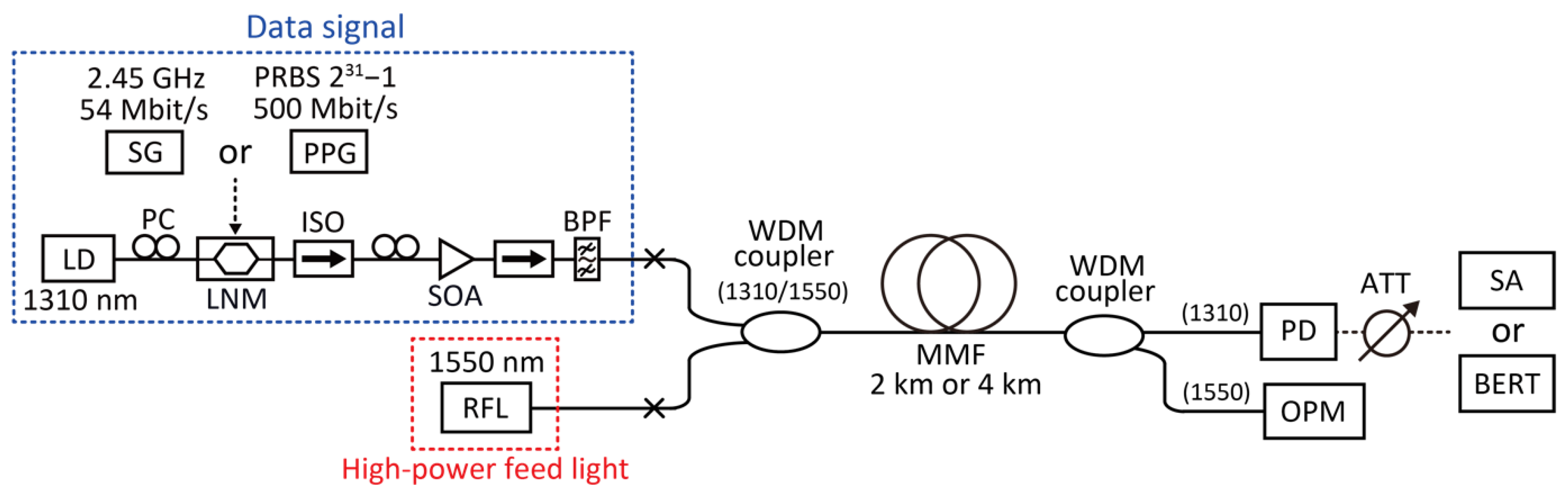
4.1. Experimental Setup

To evaluate the signal quality degradation of data signals in PWoF, we experimentally demonstrate simultaneous data signal and power transmission using an MMF. Figure 6 shows the experimental setup used for the evaluation. In this experiment, we used two types of optical data signals commonly used for short-reach optical transmission systems. One is an analog data signal, which is directly intensity-modulated by an electrical data signal. The electrical data signal generated by a signal generator (SG) was based on an IEEE802.11g wireless LAN standard, and the modulation format was orthogonally frequency division multiplexing (OFDM), 64-quadrature amplitude modulation (64-QAM). The carrier frequency and bitrate were 2.45 GHz and 54-Mbit/s, respectively. For the signal evaluation, we used a signal analyzer (SA) at the receiver side, and we measured the electrical signal spectra and the EVM characteristics. The second is a digital data signal, so called on-off keying (OOK), and commonly used to optical digital transmission systems. The electrical data were generated by a pulse pattern generator (PPG). The data pattern was based on pseudo-random bit sequence (PRBS) with a pattern length of 231–1, and the bitrate was 500 Mbit/s. For the signal evaluation, we used a BER tester (BERT), and measured the BER characteristics. In addition, we monitored the eye-pattern of the received signal to observe the effect of the transferred noise on the intensity fluctuation of the data signal. As a seed light source, we used a common LD at a wavelength of 1310 nm. The seed light was injected into a LiNbO3 modulator (LNM) and intensity-modulated by the electrical analog or digital data signal after adjusting the state of polarization of the seed light to optimize the modulation performance. After amplification by a 1310 nm semiconductor optical amplifier (SOA), the data signal was injected into a WDM coupler. Isolators (ISOs) at the input and output of the SOA were used to prevent the laser oscillation by the SOA. A bandpass filter was used to remove the amplified spontaneous noise from the SOA. As a feed light source, we used a 1550-nm RFL with an output power of up to 10 W, as shown in Figure 2. The following setup was the same as that shown in Figure 2, except for the SA and BERT at the receiver side.

4.2. Analog Signal Tranmission

Figure 7a shows the EVM penalties to the back-to-back signal of the transmitted data signal to the 2 km and 4 km MMF transmission. The back-to-back signal indicates direct detection between the two WDM couplers without MMF, as shown in Figure 6, and the EVM value was 0.98%. As the laser output power of the RFL increased, the EVM penalties increased. This trend has been also observed in PWoF using SMFs [3,4]. In particular, in Ref. [3], the different characteristics have been observed for a conventional SMF and non-zero dispersion shifted fiber with each different core diameter and refractive index profile. This means that the transmission performance also depends on these parameters of optical fibers. In our experiment, the values increased more steeply for the 4 km transmission, and the EVM could not be measured at laser powers above 6 W. Figure 7b–d show the electrical spectra of the transmitted analog data signal after 0 km, 2 km, and 4 km transmissions, when the output power of the RFL was set to 5 W or 10 W, respectively. In the 0 km transmission, no significant noise components were observed because the intensity noise transfer was not induced. However, as the transmission distance increased, the noise components increased, owing to the intensity noise transfer induced by the longitudinal mode beating and the mode partition noise of the RFL in the MMF. In the 2 km transmission, it can be seen that the signal spectrum included the 10 MHz comb component, which caused degradation of the signal quality. A larger amount of noise was transferred to the signal at a longer transmission distance. In the 4 km transmission, the 10 MHz comb component could be clearly observed. In addition, as the comb component increased, the signal spectral component decreased. This is the reason for the sharp and unmeasurable increase in the EVM penalty, as shown in Figure 7a. Although MMFs have a larger core area and lower nonlinearity than SMFs, it was clearly observed that the intensity noise transfer of the feed light strongly affects the analog data transmission performance in PWoF using single-core optical fibers.

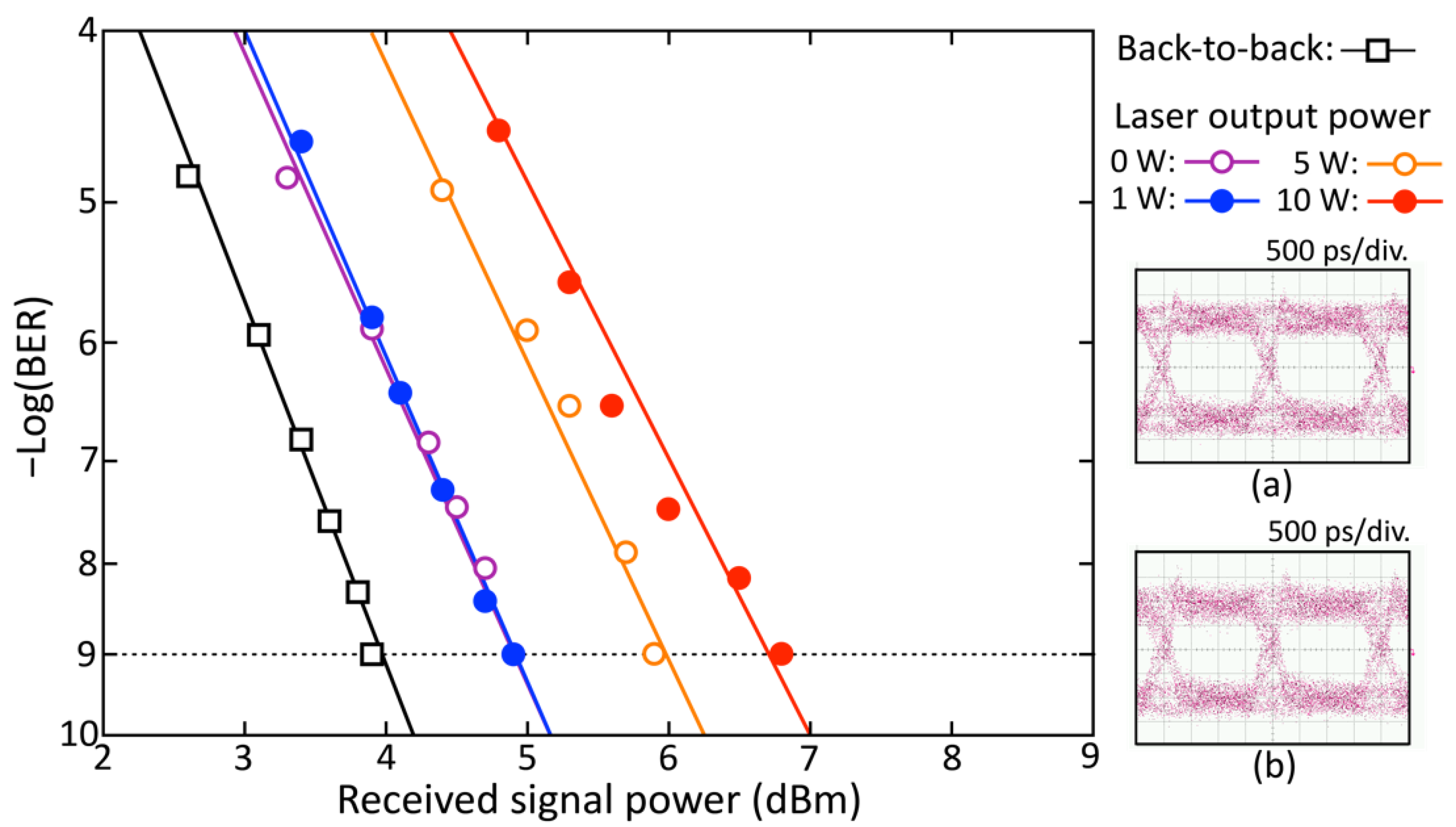
4.3. Digital Signal Tranmission

To evaluate the effect of crosstalk between the digital data signal and feed light as well, the BER characteristics of the transmitted digital data signal were measured. Figure 8 shows the BER characteristics and the eye-patterns of the transmitted digital data signal into a 2 km MMF. The power penalty between the back-to-back and the transmitted digital data signals when the laser output power of the feed light was set to 0 W was mainly due to the modal dispersion of the 2 km MMF. However, there was little difference in the power penalty between the 0 W and 1 W laser output powers because there was almost no crosstalk with the digital data signal at a laser output power of 1 W, which was consistent with the analog data signal transmission performance, as shown in Figure 7. However, as the laser output power increased, the power penalty also increased. In the 10 W laser output power, the penalty to the back-to-back signal was approximately 2.9 dB. The insets show the eye-patterns of the transmitted digital data signal when the laser output power was set to 0 W and 10 W, respectively. It can be clearly seen that the intensity fluctuations at the mark and space levels increased in the 10 W laser output power.
Figure 9 shows the BER characteristics and eye-patterns of the digital signal transmitted into a 4 km MMF. In this case, there was little difference in the power penalty between the 0 W and 1 W laser output powers. However, as the laser output power increased, the power penalty also increased. The insets show the eye-patterns of the transmitted data signals when the laser output power was set to 0 W and 10 W, respectively. Although the waveform distortion was observed even at 0 W laser input power owing to mode dispersion, larger intensity fluctuations at the mark and space levels were observed at 10 W laser input power. This was due to the intensity noise transfer induced by the longitudinal mode beating and mode partition noise of the RFL. The power penalty to the back-to-back signal was approximately 4.7 dB. It was clearly observed that the intensity noise transfer of the feed light not only significantly affects the analog data, but also influences digital data signal transmission performance in PWoF systems using single-core optical fibers.
The results of the BER measurements are summarized in Figure 10. Here, the power penalty represents the extra received signal power from the back-to-back signal required to obtain a BER = 10−9. For both the 2 km and 4 km transmissions, it can be seen that the penalty increased as the laser output power increased. In particular, the increasement of the power penalties was higher from 1 to 5 W than from 5 to 10 W, and greater for 2 km than 4 km transmission. This is related to the intensity noise spectra of the RFL, as shown in Figure 3 and Figure 4. In Figure 3, the spectral broadening from 1 to 5 W was more pronounced than that from 5 to 10 W. This rapid increase in the spectral broadening caused a large mode partition noise, and was a major factor in the degradation of the transmission performance. On the other hand, in Figure 4, the increase in noise floor from 1 to 5 W was also more pronounced. Therefore, the power penalty increase from 1 to 5 W was also larger than from 5 to 10 W in the BER measurement. This effect was more pronounced because the electrical spectrum of digital signals had a much wider bandwidth than that of analog signals.

5. Conclusions

We experimentally investigated and evaluated the crosstalk between data signals and feed light in PWoF using MMFs. We compared and evaluated the intensity noise spectra of RFLs with different laser powers and transmission distances. We showed the longitudinal mode beating and mode partition noise of the RFL are representative intensity noises, which strongly depend on the laser output power and fiber transmission distance. Furthermore, we experimentally observed that the intensity noise component was transferred to the data signal light by simultaneous transmission with the data signal light. We also quantitatively evaluated the signal degradation in terms of EVM and BER measurements and found that it was consistent with the dependence of these intensity noises on the laser output power and fiber transmission distance. The obtained results will be useful in the study of feed light sources and fibers required to suppress crosstalk when simultaneously transmitting data signals and feed light in PWoF using MMFs in the future.

Author Contributions

Conceptualization and methodology, M.M. and H.K.; investigation, A.I. and Y.K.; data curation, A.I. and Y.K.; writing—original draft preparation, M.M.; writing—review and editing, M.M. All authors have read and agreed to the published version of the manuscript.

Funding

This research received no external funding.

Institutional Review Board Statement

Not applicable.

Informed Consent Statement

Not applicable.

Data Availability Statement

Not applicable.

Conflicts of Interest

The authors declare no conflict of interest.

References

  1. Rosolem, J.B. Power-over-fiber applications for telecommunications and for electric utilities. In Optical Fiber and Wireless Communications; Róka, R., Ed.; IntechOpen: London, UK, 2017; Chapter 13; pp. 255–278. [Google Scholar]
  2. Matsuura, M. Recent advancement in power-over-fiber technologies. Photonics 2021, 8, 335. [Google Scholar] [CrossRef]
  3. Al-Zubaidi, F.M.A.; López-Cardona, J.D.; Montero, D.S.; Vázquez, C. Optically powered radio-over-fiber systems in support of 5G cellular networks and IoT. IEEE J. Lightwave Technol. 2021, 39, 4262–4269. [Google Scholar] [CrossRef]
  4. Al-Zubaidi, F.M.A.; López-Cardona, J.D.; Montero, D.S.; Vázquez, C. Power-over-fiber impact on 5G NR transmission in standard single mode fibers. In Proceedings of the International Topical Meeting on Microwave Photonics (MWP), Virtual Online, 15–17 November 2021; pp. 1–4. [Google Scholar]
  5. Lethien, C.; Wake, D.; Verbeke, B.; Vilcot, J.-P.; Loyes, C.; Zegaoui, M.; Gomes, N.; Rolland, N.; Rolland, P.-A. Energy-autonomous picosecond remote antenna unit for radio-over-fiber system using the multiservice concept. IEEE Photon. Technol. Lett. 2012, 24, 649–651. [Google Scholar] [CrossRef]
  6. Kuboki, H.; Matsuura, M. Optically powered radio-over-fiber system based on center- and offset-launching techniques using a conventional multimode fiber. Opt. Lett. 2018, 43, 1057–1070. [Google Scholar] [CrossRef] [PubMed]
  7. Vázquez, C.; López-Cardona, J.D.; Lallana, P.C.; Montero, D.S.; Al-Zubaidi, F.M.A.; Pérez-Prieto, S.; Garcilópez, I.P. Multicore fiber scenarios supporting power over fiber in radio over fiber systems. IEEE Access 2019, 7, 158409–158418. [Google Scholar] [CrossRef]
  8. López-Cardona, J.D.; Rommel, S.; Grivas, E.; Montero, D.S.; Dubov, M.; Kritharidis, D.; Tafur-Monroy, I.; Vázquez, C. Power-over-fiber in a 10 km long multicore fiber link within a 5G fronthaul scenario. Opt. Lett. 2021, 46, 5348–5351. [Google Scholar] [CrossRef] [PubMed]
  9. Umezawa, T.; Kashima, K.; Kanno, A.; Matsumoto, A.; Akahane, K.; Yamamoto, N.; Kawanishi, T. 100-GHz fiber-fed optical-to-radio converter for radio- and power-over-fiber transmission. IEEE Sel. Top. Quantum. Electron. 2017, 23, 3800508. [Google Scholar] [CrossRef]
  10. Matsuura, M.; Sato, J. Bidirectional radio-over-fiber systems using double-clad fibers for optically powered remote antenna units. IEEE Photon. J. 2015, 7, 7900609. [Google Scholar] [CrossRef]
  11. Matsuura, M.; Tajima, N.; Nomoto, H.; Kamiyama, D. 150-W power-over-fiber using double-clad fibers. IEEE/OSA J. Lightwave Technol. 2020, 38, 401–408. [Google Scholar] [CrossRef]
  12. Matsuura, M. Power-over-fiber using double-clad fibers. IEEE J. Lightwave Technol. 2022. to be published. [Google Scholar] [CrossRef]
  13. Fludger, C.R.S.; Handerek, V.; Mears, R.J. Pump to signal RIN transfer in Raman fiber amplifiers. IEEE J. Lightwave Technol. 2021, 39, 4511–4516. [Google Scholar] [CrossRef]
  14. Martinelli, C.; Lorcy, L.; Durécu-Legrand, A.; Mongardien, D.; Borne, S. Influence of polarization on pump-signal RIN transfer and cross-phase modulation in copumped Raman amplifiers. IEEE J. Lightwave Technol. 2006, 24, 3490–3505. [Google Scholar] [CrossRef]
  15. Babin, S.A.; Churkin, D.V.; Fotiadi, A.A.; Kablukov, S.I.; Medvedkov, S.I.; Podivilov, E.V. Relative intensity noise in cascaded Raman fiber laser. IEEE Photon. Technol. Lett. 2005, 17, 2533–2555. [Google Scholar] [CrossRef]
  16. Ikukawa, A.; Kuboki, H.; Matsuura, M. Relative phase noise evaluation of power-over-fiber in multimode fibers. In Proceedings of the 1st Optical Wireless and Fiber Power Transmission Conference (OWPT 2019), Yokohama, Japan, 23–25 April 2019; p. OWPT-P-09. [Google Scholar]
  17. Kawamura, Y.; Matsuura, M. Evaluation of relative intensity noise for power-over-fiber using multimode fibers. In Proceedings of the 25th OptoElectronics and Communications Conference 2020 (OECC 2020), Online, 4–8 October 2020. VP63. [Google Scholar]
  18. Wentworth, R.H.; Bodeep, G.E.; Darcie, T.E. Laser mode partition noise in lightwave systems using dispersive optical fiber. IEEE J. Lightwave Technol. 1992, 10, 84–89. [Google Scholar] [CrossRef]
Figure 1. Schematic view of simultaneous data signal and high-power feed light transmission using a single core, conventional multimode fiber.
Photonics 09 00369 g001
Figure 2. Experimental setup for intensity noise evaluation of RFL. WDM coupler: Wavelength-division-multiplexing coupler, PD: Photodiode, ATT: Attenuator, ESA: Electrical spectrum analyzer, OPM: Optical power meter.
Photonics 09 00369 g002
Figure 3. Electrical spectra of RFL output without transmission (0 km) when laser output power was set to (a) 1 W, (b) 5 W, and (c) 10 W, respectively. Insets show expanded spectra in frequency range between 0 and 100 MHz.
Photonics 09 00369 g003
Figure 4. Electrical spectra of RFL output after (a) 0 km, (b) 2 km, and (c) 4 km transmission when laser output power was set to 5 W, respectively. Insets show expanded spectra in frequency range between 0 and 100 MHz.
Photonics 09 00369 g004
Figure 5. Example of 20 dB bandwidth and noise level of electrical spectra of RFL output after 2 km transmission while varying laser output power.
Photonics 09 00369 g005
Figure 6. Experimental setup for simultaneous data signal and power transmission using an MMF. PPG: Pulse pattern generator, SG: Signal generator, LD: Laser-diode, PC: Polarization controller, LNM: LiNbO3 modulator, ISO: Isolator, SOA: Semiconductor optical amplifier, BPF: Bandpass filter, RFL: Raman fiber laser, WDM coupler: Wavelength-division-multiplexing coupler, PD: Photodiode, ATT: Attenuator, SA: Signal analyzer, BERT: BER tester, OPM: Optical power meter.
Photonics 09 00369 g006
Figure 7. (a) EVM characteristics of data signal while changing laser output power after 2 km and 4 km MMF transmission. (bd) Electrical signal spectra of data signal for various transmission lengths and laser output powers.
Photonics 09 00369 g007
Figure 8. BER characteristics of digital data signal transmitted into 2 km MMF for various laser output powers. Insets show eye-patterns of transmitted data signal when laser output powers were (a) 0 W and (b) 10 W, respectively.
Photonics 09 00369 g008
Figure 9. BER characteristics of digital data signal transmitted into 4 km MMF for various laser output powers. Insets show eye-patterns of transmitted data signal when laser output powers were (a) 0 W and (b) 10 W, respectively.
Photonics 09 00369 g009
Figure 10. Power penalties to back-to-back signal of the data signal transmitted to the 2 km and 4 km MMF transmissions while varying laser output power characteristics of digital data signal transmitted into 4 km MMF for various laser output powers.
Photonics 09 00369 g010
Publisher’s Note: MDPI stays neutral with regard to jurisdictional claims in published maps and institutional affiliations.

