Recent Advancement in Power-over-Fiber Technologies


Graduate School of Informatics and Engineering, University of Electro-Communications, 1-5-1 Chofugaoka, Chofu, Tokyo 182-8585, Japan
Photonics 2021, 8(8), 335; https://doi.org/10.3390/photonics8080335
Submission received: 26 May 2021
/
Revised: 10 August 2021
/
Accepted: 12 August 2021
/
Published: 15 August 2021
(This article belongs to the Special Issue Latest Papers Related to OWPT 2019-22 on the Topics of Photovoltaic Components, Devices and Systems)
Abstract
:Power-over-fiber is a power transmission technology using optical fibers that offers various features not available in conventional power lines, such as copper wires. The basic configuration of power-over-fiber comprises three key components: light sources, optical fibers, and photovoltaic power converters. This review article presents the features of power-over-fiber and its key components. Moreover, recent advancement in power-over-fiber technologies based on their latest results is introduced, focusing primarily on papers presented at the Optical Wireless and Fiber Transmission Conferences (OWPT) from 2019 to 2021.
1. Introduction
Power-over-fiber (PWoF) has a considerable mature technology, and its research and development have been conducted since the late 1970s [1,2]. In those days, the cost of PWoF was much higher than those of conventional power lines, such as copper wires, and the performance of related components, such as light sources and photovoltaic power converters (PPCs), had to be improved considerably. However, approximately 40 years have passed since the introduction of PWoF technologies. Its key components, including optical fibers, have undergone significant developments; consequently, PWoF has become more sophisticated and is now being developed into various application technologies.
Owing to the development of PWoF technologies, features that are not available in conventional power supply systems are now realized, e.g., lightweightness, corrosion resistance, and robustness to electromagnetic interference (EMI) and electric sparks. Consequently, the application field of PWoF has expanded significantly. In particular, optical fibers, which are widely used as high-speed communication lines, are expected to significantly affect future infrastructure facilities by enabling telecommunication, sensing, and power transmission.
The features of PWoF and its key components are presented herein. Moreover, recent advancement in PWoF technologies based on their latest results is introduced. Previously, as a review article, Rosolem, J. B. introduced PWoF applications for telecommunications and electric utilities in 2017 [3]. In contrast, this article reviews the latest advancement in PWoF technologies, especially focusing primarily on papers presented at the Optical Wireless and Fiber Transmission Conferences (OWPT) [4] from 2019 to 2021, which included topics pertaining to high-power lasers, PPCs, optical wireless and fiber power transmission systems, and wireless power transmission systems. This international conference was held for the first time in 2019 in Yokohama, Japan. In 2021, it was held for the third time, and experts in optical power transmission convened and exchanged ideas, and the latest research results in this field were reported. Therefore, this article focuses primarily on papers related to PWoF published at OWPT in the past three years and introduces the latest trend in PWoF technologies.
The remainder of this paper is organized as follows. In Section 2, the features of PWoF and its key components are presented. In Section 3, research pertaining to optically powered sensor systems that utilize optical fibers as non-conductive power lines is introduced. In Section 4, research pertaining to optically powered remote antenna units for applications in telecommunications is introduced. In Section 5, an integrated optical data transmission system is introduced. Finally, conclusions are provided in Section 6.
2. Features of PWoF
PWoF systems comprise three key components: light sources, optical fibers, and PPCs. The optical power from a light source propagates through an optical fiber and is converted into electrical power via a PPC. The converted power can be used to drive electronic devices in remote units. In this system, the delivered electric power and power transmission efficiency are the two important factors. The former is an indicator of the amount of transmittable electric power, whereas the latter is an indicator of the efficiency of electric power transmission. To satisfy these requirements, the performances of the key components are critical. In addition, PWoF systems will be more attractive if a single optical fiber can transmit data signals for sensors and telecommunications simultaneously. The features of each PWoF component are described below. Content similar to that provided in this section is presented comprehensively in [5] as a design guidance; therefore, this paper can also be used as a reference when constructing PWoF systems.
2.1. Light Sources
High-power laser diodes (HPLDs) and fiber lasers are often used as light sources for PWoF systems. Fiber-pigtailed HPLDs are typically used as commercial products from the view point of connectivity with optical fibers. Regarding HPLDs, their operating wavelength and output power depend significantly on the composition of the material. In particular, 808, 830, and 980 nm are the major wavelength bands in PWoF systems. In fiber-pigtailed HPLDs, to inject the output lights from multiple LD chips into an optical fiber, an optical fiber with a larger core diameter is advantageous in order to inject more power into the optical fiber. For fiber-pigtailed HPLDs exceeding 10 W, it becomes difficult to inject high-power light into conventional small core. For optical fibers with an outer diameter of 125 μm, which is typically used in optical fiber communications, the output power is generally limited to 40 W or less. The electrical-to-optical (E/O) conversion efficiency of HPLDs, which depends on the composition of the material, is generally between 30% and 50%.
Regarding high-power fiber lasers, their operating wavelength and output power depend significantly on the configuration of laser cavity. In particular, since Raman fiber lasers enable us to control the oscillation wavelength by utilizing stimulated Raman scattering (SRS) in the cavity, it is possible to provide high-power lasers in the 1480 nm and 1550 nm bands. In addition, since the cavity composes an optical fiber, it can be easily connected to an optical fiber for transmission. On the other hand, fiber lasers give rise to mode partition noise due to multimode oscillation [6], which degrades signal quality when transmitted simultaneously with data signals [7].
2.2. Optical Fibers and Connectors
Conventional silica optical fibers have a simple waveguide structure comprising a core and a cladding; however, even in PWoF, the difference in the structure results in a significant difference in performance. In particular, when high-power light is injected into an optical fiber with a small core, nonlinear effects, such as SRS and stimulated Brillouin scattering, occur in the core, which can cause significant signal degradation in data signals when transmitted simultaneously with data signals. The development of optical fiber communications in recent years has enabled the development of various optical fibers. The structures of each optical fiber and its features when used in PWoF are shown below.
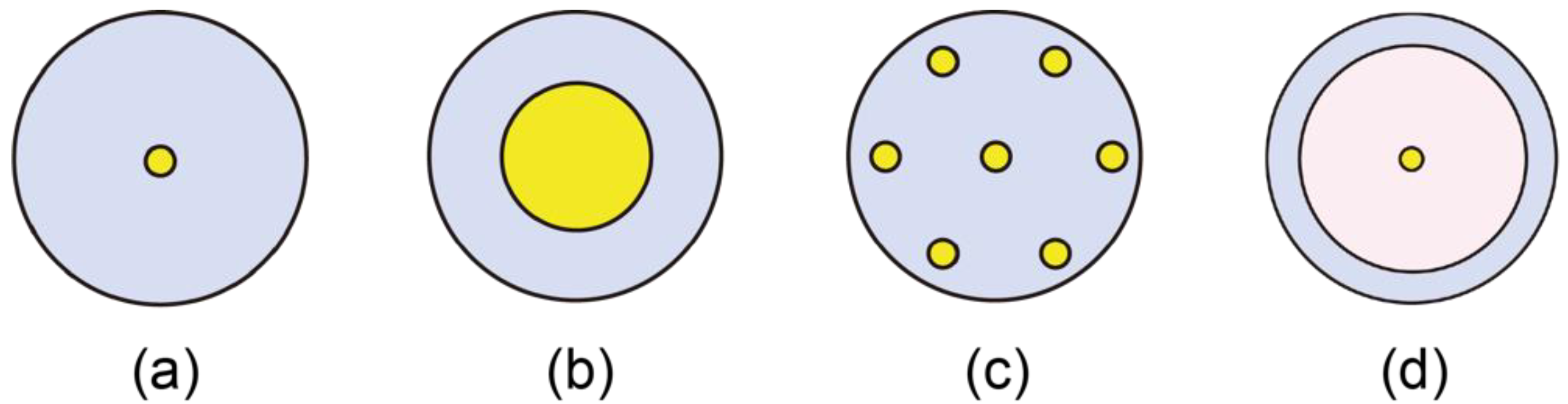
Figure 1 shows the cross sections of various types of optical fibers for PWoF [8]. Single-mode fibers (SMFs) are still widely used as a highly versatile optical fiber. One of its features is that the core diameter through which the optical signal propagates is as small as 8–10 μm; therefore, the optical signal is transmitted in a single propagation mode. Consequently, bandwidth limitations are not applicable owing to the propagation delay between modes, and broadband signal transmission is possible. By contrast, high-power feed light transmission for PWoF is difficult to achieve owing to the extremely high-power density, which gives rise to critical damage to the fiber such as fiber fuse [9]. Multimode fibers (MMFs) have a larger core diameter than SMFs and are advantageous for high-power transmission. However, MMFs have many propagation modes, thereby resulting in transmission bandwidth limitations owing to modal propagation delay. Multi-core fibers (MCFs) exhibit structures comprising multiple cores, as shown in Figure 1c, and have high data capacity that corresponds to the number of cores. In PWoF, although the diameter of the core is small, optical signals and feed light can be transmitted simultaneously using multiple cores. Double-clad fibers (DCFs) has been primarily used as a gain medium for high-power lasers and optical amplifiers. By injecting optical signals to be amplified into the central small-diameter core and pumping light for optical amplification into the outer inner cladding, a DCF can be operated as an optical amplifier with high gain. By contrast, in PWoF, by injecting optical signals into the central, rare-earth undoped core and by feeding light into the large-diameter inner cladding, broadband transmission for optical signals and high-power transmission for feed light can be realized simultaneously. In Section 3, the actual applications of PWoF systems using these fibers are described comprehensively.
In addition to the abovementioned fibers, hollow-core fibers (HCFs) are attractive optical fibers that have recently garnered significant attention [10,11]. This fiber enables the transmission of optical signals by confining them in a hollow region corresponding to the core. Because optical signals propagate in air, the propagation speed is expected to be increased to approximately 1.5 times faster than those of silica-core optical fibers such as SMFs, MMFs, MCFs, and DCFs. This will be advantageous for optical fiber transmission in a 5th Generation (5G) Mobile Communication System, where ultra-low latency signal transmission is required. Moreover, because the core of HCPs is air, it is highly resistant to the input optical power, and is less susceptible to various phenomena that occur in silica-core optical fibers, such as chromatic dispersion, nonlinear effects, and modal noise in the fiber. By contrast, HCFs exhibit a complicated cross-sectional structure that can efficiently confine light in its hollow core [10,11]; currently, long-distance spinning in HCFs is difficult to achieve as many issues remain to be solved before the practical stage can be reached. As for PWoF technologies using other optical fibers, simultaneous signal and power transmission experiments using a large-core microstructure optical fiber [12] and a step-index plastic optical fiber [13] have also been reported recently.
As feed light power increases, optical connectors become more important. In particular, an SMF with a small core has an extremely high power density, which causes the optical fiber connections to be damaged easily and limits the transferable optical power. A practical approach for solving this problem is to use an expanded beam connection based on ferrules terminated with graded-index fibers (the core diameter of 25 or 50 μm); this method offers the advantage of superior high-power connection performance of up to 16 W in terms of insertion and return losses [14]. Another alternative is to splice the fibers [15]. In PWoF, both higher power tolerance and lower connection loss are to be achieved.
2.3. PPCs
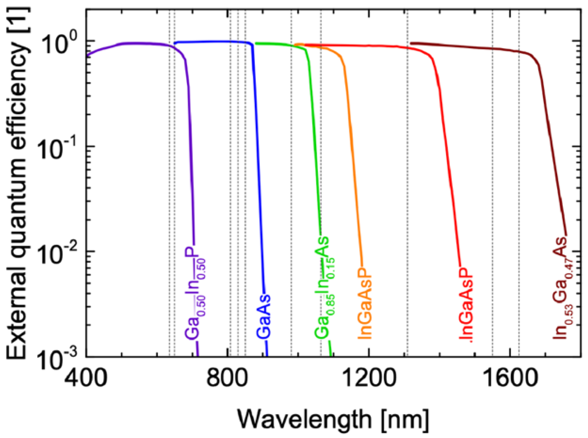
PPCs are essential elements in PWoF, and enable us to convert input optical power into electrical power. The PPC characteristics significantly affect the performances of optical wireless and fiber power transmission systems. For PWoF applications, PPCs must be of a compact size to match the beam diameter output from the optical fiber end-face. In addition, unlike solar cells, PPCs convert optical power from a laser source into electric power; hence, it exhibits conversion characteristics specific to certain wavelengths, which depend significantly on the composition material. Figure 2 shows an example of the external quantum efficiency of various PPC cells based on III-V compound semiconductor materials [16]. As shown, PPCs for various wavelength bands can be fabricated by selecting the appropriate composition materials. Next, PPCs that are currently being widely researched and developed extensively for each wavelength band are introduced.
Most PPCs were developed in the 800–860 nm wavelength band, and many PPCs with high conversion efficiencies (CEs) and high performances have been reported at OWPT [16,17,18,19,20,21,22,23,24,25,26,27,28,29,30,31]. Owing to the abundance of high-performance HPLDs in this wavelength band, the latter is well known as a promising wavelength band of feed light sources for PWoF. In the latest research result, a PPC that achieved a conversion efficiency of 68.9% at 858 nm by photon recycling and optical resonance has been reported [32]. In the 960–980-nm wavelength band, many PPCs have also been reported as well because high-performance and low-cost HPLDs can be fabricated therein [19,20,21,25,26]. More recently, PPCs that support longer wavelengths, such as 1310 nm [24,27,28,29] and 1550 nm [21,30,31], have been developed. In particular, the 1550-nm band is garnering significant attention from the viewpoint of eye safety, and it is an advantageous wavelength band for both PWoF and optical wireless power transmission.
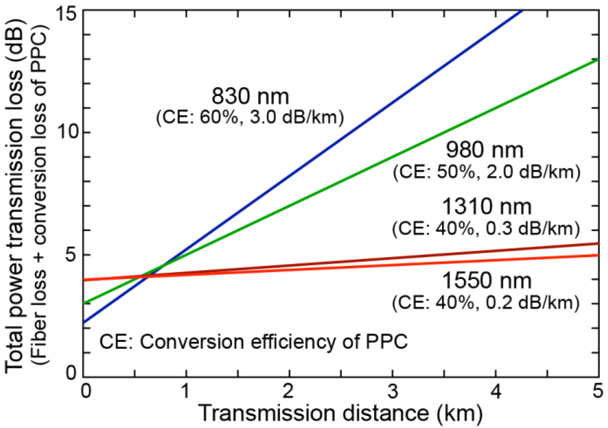
When considering the power transmission efficiency of an entire PWoF system, the wavelength of the feed light used has a significant affect, not only on the CE of the PPC, but also on the transmission loss of the optical fiber. Figure 3 shows an example of the relationship between the transmission distance and total power transmission loss determined by the sum of the fiber transmission loss and conversion loss of the PPC. In this regard, the loss at a transmission distance of 0 km indicates the conversion loss determined by the CE of the PPCs at each wavelength, and the slope of each line indicates the transmission loss of the fiber. The CE at each wavelength is the average CE of the PPCs reported in recent studies. For the transmission loss, we used the values of conventional SMFs. It should be noted that this total power transmission loss does not include the E/O conversion loss of the feed light sources. As shown in Figure 3, because a shorter wavelength feed light yields a higher CE, a lower power transmission loss will be achieved when the transmission distance is short. However, as the transmission distance increases, the fiber transmission loss becomes more dominant than the conversion loss of the PPCs, and a longer-wavelength feed light offers a lower power transmission loss. This indicates the importance of transmission distance in determining the feed light wavelength. Hence, the power transmission efficiency depends significantly on both the transmission distance and the feed light wavelength. Meanwhile, the transmitted optical power is also determined by the available output power of the light sources and the available input power of the PPCs. To develop a more efficient and higher power PWoF system, all of the abovementioned factors must be considered.
3. Optically Powered Sensor Systems
In PWoF, optically powered sensor systems using optical fibers are the most versatile application technology. In general, sensors can be driven by a small amount of electric power, and the information obtained by the sensors can be transmitted by an optical fiber. In particular, PWoF is highly valuable in places where optical fibers can be utilized as non-conductive power lines. In this section, several attractive sensor applications are discussed.
3.1. Rotor Blade Monitoring Systems
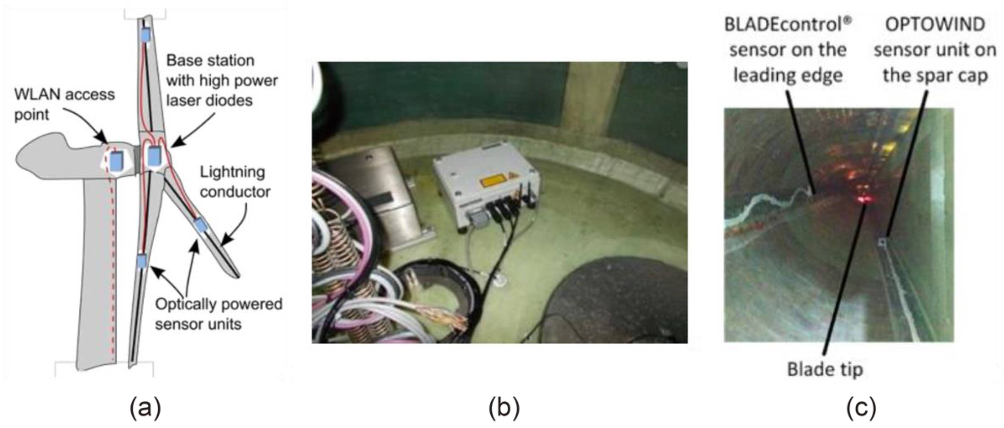
Wind energy is an attractive renewable energy source, and wind turbines are used to exploit the potential of wind energy. It is essential to monitor the blade conditions of wind turbine rotors. However, conventional electronic sensors can be damaged by lightning strikes. Klamouris, C. et al. reported an optically powered rotor blade condition monitoring system as a lightning-safe system [33]. In this system, as shown in Figure 4a, a base station with HPLDs placed in the hub of the wind turbine is connected to an optically powered sensor unit inside each rotor blade by a ruggedized optical fiber cable, which comprises two conventional MMFs with a core diameter of 62.5 μm. The feed light power at a wavelength of 830 nm in the base station is transmitted to the remote sensor unit through the fiber of the cable, whereas the acquired sensor data generated by a laser at a wavelength of 850 nm are returned to the base station by the other fiber. Subsequently, the received sensor data are further transmitted via wireless signal transmission based on a wireless local area network (WLAN) to the nacelle and then forwarded to an analyzing personal computer (PC) located in the rotor tower base. The electric power for driving the base station is supplied from the pillar using split rings [34].
In this study, the authors conducted a field trial experiment using a fully operational 3.5-MW wind turbine with a rotor diameter of 115 m. Figure 4b,c show the photographs of the base station and the inside of the rotor blade, respectively. As shown, the base station was mounted onto the bulkhead of one wind turbine rotor blade at a distance of approximately 1.8 m from the blade root. Each optically powered sensor unit was mounted onto the spar cap of each blade at a distance of 18.5 m from the bulkhead. In this system, each of the three sensor units were powered by each different feed light source, and the output optical power of each feed light source was 367 mW, because the electric power required for each sensor unit was 135 mW. The authors evaluated the performances of this system and a commercially available system (BLADEcontrol®); they successfully demonstrated that the presented system exhibited a performance equivalent to that of a commercially available system. A related study is presented comprehensively in [34].
3.2. Current and Voltage Sensors
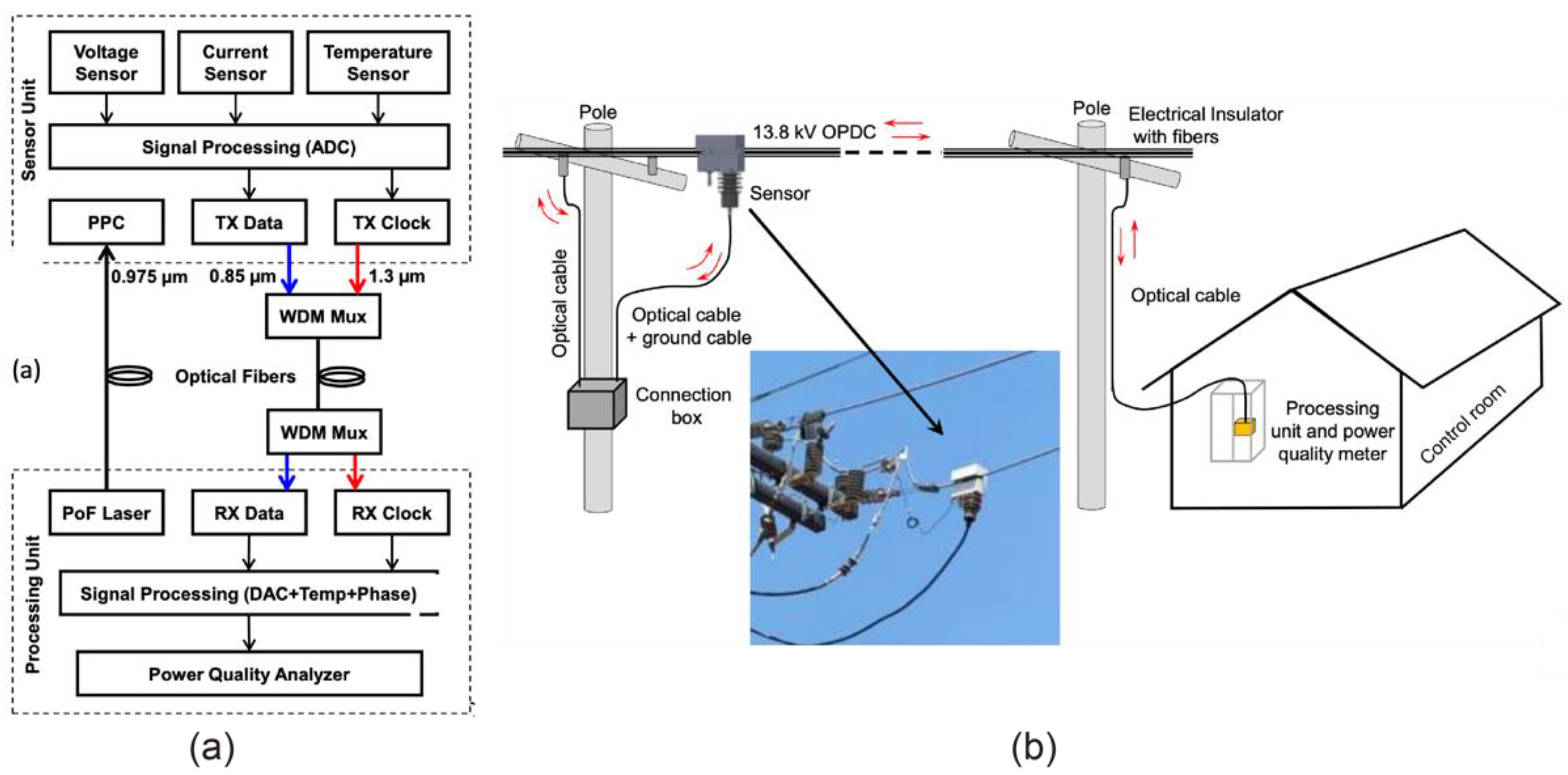
In future electric power networks, smart grid sensors will be crucial in providing real-time monitoring, protection, and control to the networks; however, they must be operated in a high-voltage environment. By contrast, because optical fibers are fabricated using non-conductive materials, the immunity to EMI is beneficial, not only for measuring currents and voltages, but also for transmitting measured signals without quality degradation in high-voltage environments. In this regard, Bassan, F. R. et al. reported an optically powered smart sensor system for electric power networks [35].
Figure 5a shows a block diagram of an optically powered smart sensor. The system comprises a sensor and processing units. The powering and communication between these units are performed using two conventional MMFs with a core diameter of 62.5 μm, which ensure high electrical insulation between the medium voltage and ground. The feed light power of 2.0 W at a wavelength of 976 nm in the processing unit is transmitted to the sensor unit through one fiber, whereas the data and clock signals generated by lasers at wavelengths of 850 nm and 1310 nm are sent to the processing unit over the other fiber. Finally, the received signal is amplified and delivered to the power quality analyzer.
To demonstrate the feasibility of the system, the authors conducted a field trial experiment using a 13.8 kV hybrid copper and fiber distribution network. Figure 5b shows a schematic illustration of the link system between the sensor and control room. The sensor was installed in a hybrid aerial fiber/power distribution cable. In this field trial, the processing unit was installed in a control room, and the sensor signals from the sensor were sent there through the cable of the distribution network. It should be noted that the optical connection boxes installed on some poles were used to provide different applications in the network. In this system, the authors evaluated the maximum distance obtained with an acceptable signal quality and recorded a value of 1.77 km. In addition, they demonstrated that accurate observations over a 30-day period were possible for various weather conditions. A related study is reported in [3].
3.3. Other Sensor Applications
In addition to the papers presented at OWPT from 2019 to 2021, various other sensor applications have recently been reported. For example, since Internet of Things (IoT) sensors require power and transmission of sensor information, PWoF is a very effective way to simplify the configuration of the system [36,37]. Underwater power transmission using cooper cables poses the risk of electrical leakage. However, this can be avoided by using optical fibers, and underwater sensors by PWoF for seafloor observatories have also been reported [15]. PWoF also plays an important role in hazardous environments such as laboratories facilities where flammable materials are used and stored in order to avoid sparks and chemical affections of copper power line cables. A PWoF experimental demonstration to drive the sensors for such an environment has been reported [38].
4. Optically Powered Remote Antenna Units
Electric power is required in telecommunication systems. Therefore, the use of optical fiber, as both a telecommunication line and a power line, is attractive in these systems. However, because telecommunication devices and equipment require high electric power, as described in the previous section, any PWoF technologies that can deliver much higher electric power than sensor applications are described. In this section, PWoF technologies for driving various types of telecommunication devices and equipment are introduced.
4.1. Remote Antenna Units for Mobile Communications
Owing to the rapid development of mobile communications, a large number of remote antenna units (RAUs) and their fiber connections are necessitated in the near future. In current mobile communication networks, the electric power required to drive RAUs is generally supplied by nearby commercial power lines. However, if the power with mobile data can be transmitted using a single optical fiber to an RAU, then the construction of a simple RAU system that does not require electrical work will be enabled, and the RAU will be extremely easy to install and operate. However, the power required to drive a small-cell RAU exceeds 10 W, which is much higher than the power that can be transmittable via conventional PWoF technologies.
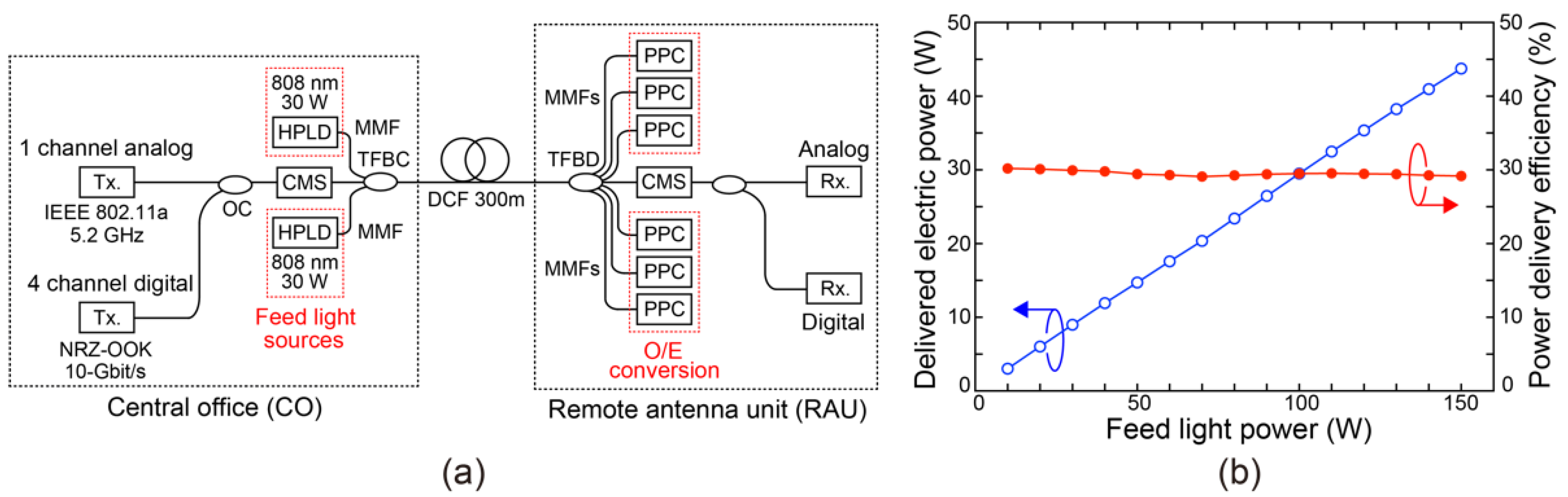
Hence, Matsuura, M. et al. reported a high-power PWoF system using a DCF, as shown in Figure 1d, to drive an RAU by increasing the core area for transmitting the feed light by more than 200 times compared with SMFs [8]. Figure 6a shows an example of the configuration of an optically powered RAU using a 300-m DCF. In this scheme, multichannel optical signals are transmitted to the center core of the 300-m DCF. Simultaneously, the feed light generated by the two HPLDs is transmitted to the outer core (inner cladding) of the DCF. The maximum output power of the feed light injected into the system is 60 W. In the DCF link, because specific components for combining and dividing the optical signals and the feed light are required, the system uses a customized tapered-fiber-bundle combiner (TFBC) and tapered-fiber-bundle divider (TFBD). In addition, to remove the reflected and residual feed light components in the inner cladding of the DCF, cladding power strippers (CPSs) are inserted at the input of the TFBC and the output of the TFBD. The loss of the inner cladding of the DCF is approximately 3.3 dB/km at a wavelength of 808 nm, which is the wavelength of the feed light we used. After transmission, the optical signals are converted into an electrical signal, and signal qualities are measured, feed light power is converted into electric power using six PPCs, and delivered total electric power is measured.
The signal qualities of the transmitted signals were measured to evaluate the transmission performance of the optical signals under high-power feeding. Consequently, it was confirmed that high signal qualities were maintained regardless of the input power of the feed light. By contrast, the transmitted electric power was 7 W for a feed light of input power 60 W, and the power delivery efficiency, which is defined as the power ratio between the input feed light power and the delivered electric power, was 11.7%. The related studies are presented in Refs. [39,40,41].
Recently, the authors successfully demonstrated a higher-power PWoF system experimentally using a 300-m DCF. In the experiment, the input power of the feed light was increased up to 150 W, and the power transmission efficiency of the DCF was increased by improving the system design. In addition, by introducing a custom-developed PPC from Broadcom, Inc. [18,19], they successfully transmitted up to 43.7 W of electric power [42]. Figure 6b shows the delivered electric power and power delivery efficiency of the system as a function of the input feed light power injected into the system. This result shows that the power delivery efficiency not only increased to approximately 30%, but also exhibited high linearity with respect to the input power of the feed light.

4.2. Optical-to-Radio Converter Module
MCF is a practical optical fiber for simultaneous transmission of data signals and power by effectively utilizing multiple cores, and several experimental demonstrations have been reported for driving RAUs so far [43,44,45,46].
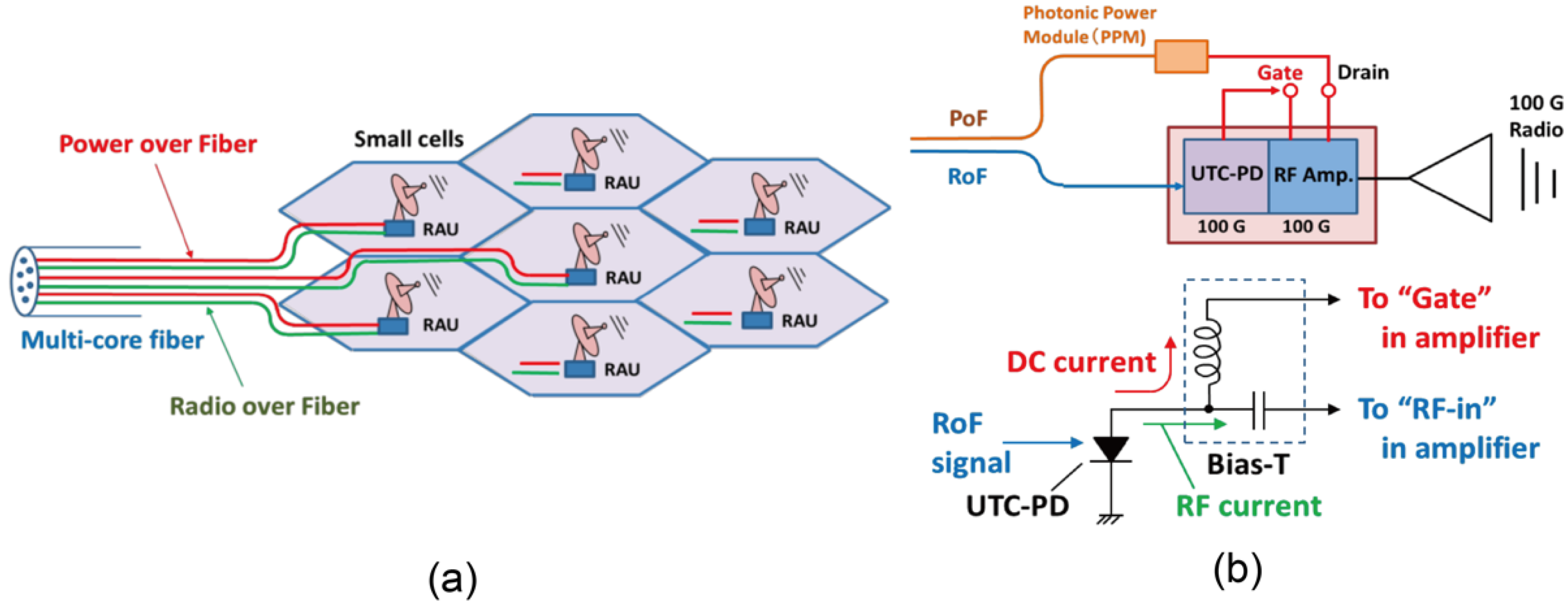
In simple RAUs for small cells, the key components are the photo-diode (PD) and electrical amplifier. Umezawa T. et al. reported an optically powered optical-to-radio converter (ORC) module, which comprised a broadband PD and an electrical amplifier, based on an MCF, as shown in Figure 1c [43].
Figure 7a shows the configuration of the mobile communication network with an optically powered RAU. Using an MCF, the power to drive the ORC module and the optical signals for the RAU can be transmitted in separate cores. Figure 7b shows a schematic illustration of the ORC module and a detailed circuit diagram. The ORC module primarily comprises a bias-free 100-GHz uni-traveling-carrier photo-diode (UTC-PD) and an RF amplifier.
In this scheme, the amplifier requires a gate bias with a low power and a drain bias with a high power. Therefore, the gate bias can be supplied from the optical modulated average power (DC current) converted by the UTC-PD, whereas the drain bias can be supplied from the electric power delivered by PWoF using one of the cores of the MCF. In this study, the authors successfully achieved a high RF output power of +6 dBm at 97 GHz by supplying an electric power of up to 50 mW via PWoF. Consequently, they achieved a gain that was 21 dB higher compared with that achieved using only a single UTC-PD. The related studies are reported in [44,45].
As shown above, the use of MCF is a practical way for simultaneous transmission of signal and power by effectively utilizing multiple cores, although the transmittable optical power is limited by the number of cores and its total core area. In order to evaluate its effectiveness and performance limits, Vázquez C. et al. reported a detailed simulation and experimental evaluation of PWoF using MCFs [46].
4.3. Microwave Amplifiers for Radio Stations
Microwave radio communication system is useful for monitoring and controlling electric power grid facilities. In such a system, a parabola antenna for line-of-sight communications is placed at the top of radio towers and connected to a radio station building via a conductive metal waveguide. However, if the radio towers are struck by strong lightning, then the electrical equipment in the radio station building will be damaged severely. Hence, Ikeda, K. et al. proposed a system configuration using optical fibers instead of conductive metal waveguides in order to protect the equipment from lightning. In that study, they reported a newly developed, optically powered microwave amplifier that provides applicable RF-transmitting power [47].
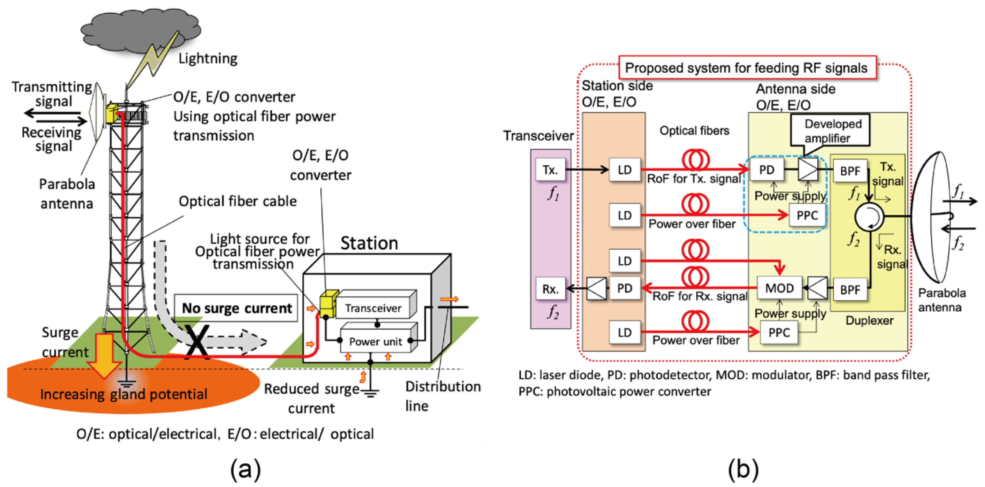
The configuration of an entire radio station system is shown in Figure 8a. RF signals for microwave radio communication are transmitted and received using bidirectional RoF links between the parabola antenna at the top of the radio tower and the transceiver placed in the radio station. In addition, if the electrical power for driving the E/O and optical-to-electrical (O/E) converters on the antenna side can be transmitted via PWoF, then the construction of a system, in which the parabola antenna and the radio station are connected only by optical fibers, i.e., whereby no surge current reaches the station, can be realized.
Figure 8b shows a block diagram of the system. The key component of the system is an optically powered E/O converter, which comprises an InGaAs PIN photodiode with five-stage electrical amplifiers, for acquiring an applicable RF power exceeding 100 mW (20 dB). The power indicated is a typical transmission level in industrial microwave stations. To drive the converter, a feed light at a wavelength of 976 nm was transmitted using a paired PWoF system comprising an HPLD with a maximum output power of 10 W, an MMF with a core diameter of 105 μm, and a silicon-based PPC. In this system, a total electric power exceeding 4 W was supplied to the electrical amplifier. Consequently, an optically powered microwave amplifier system with a practical output power and negligible signal degradation was achieved.
5. Integrated Optical Data Transmission System
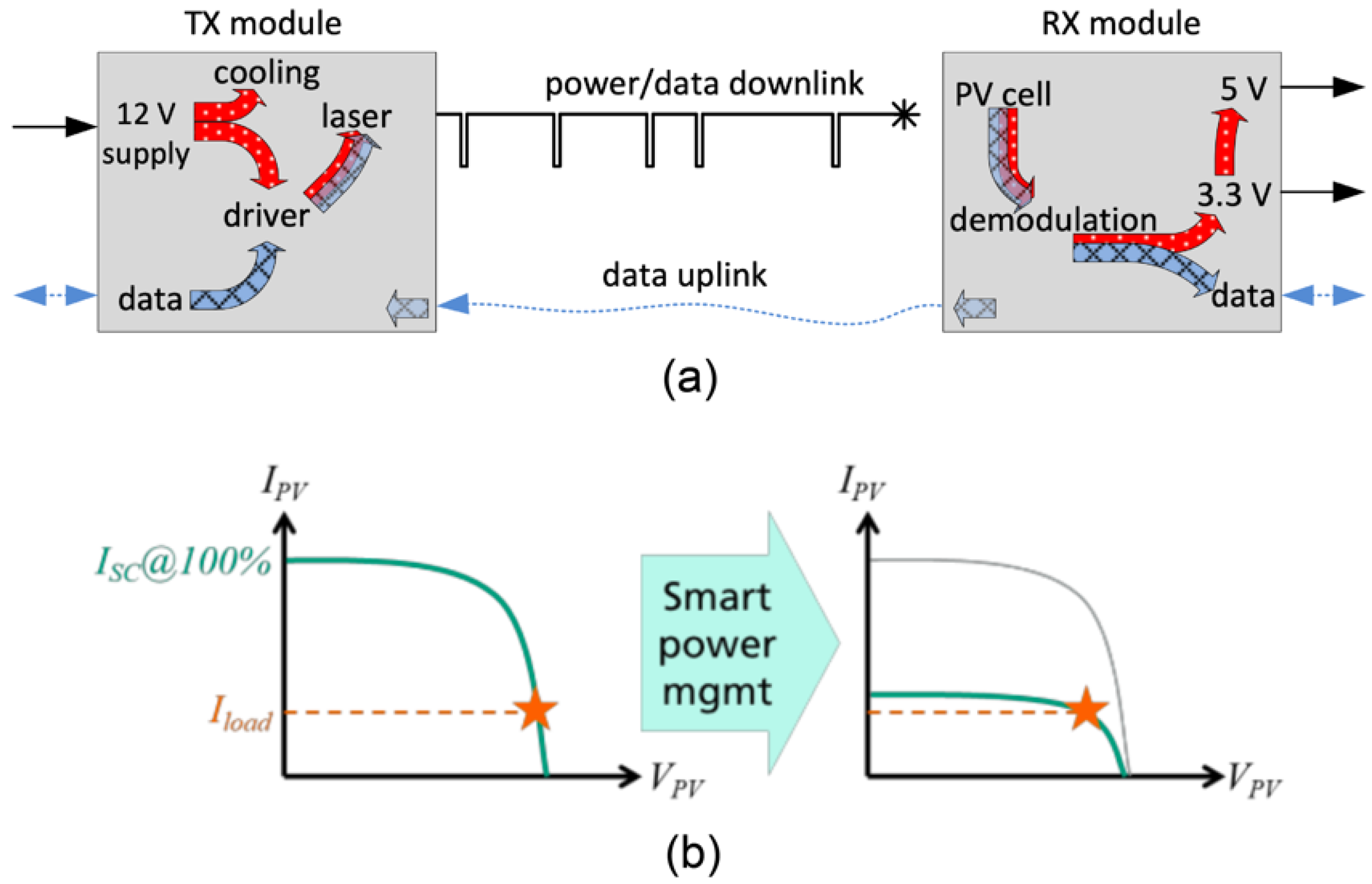
Simultaneous transmission of data signals and power over a single optical fiber is a practical application in PWoF. In Section 4.1 and Section 4.2, the simultaneous transmission techniques using a DCF and an MCF were introduced, respectively. In addition to these techniques, Haid, M. et al. reported an integrated optical data transmission system [48]. Figure 9a illustrates the basic concept of the system. The salient point is that the simultaneous transmission of optical data and power is achieved by transmitting a single amplitude-modulated feed light. On the transmitter (TX) side, the module hosts an HPLD with a wavelength of 809 nm and an output power of up to 15 W as well as the respective laser driver, thereby enabling data modulation in the HPLD using a microcontroller (μC). The digital data input to the TX module is converted into a modified infrared data association (IrDA) signal from the μC. Moreover, to achieve a high average power from the feed light, the pulse width of the IrDA signal is reduced to 100 ns, and the logic is inverted, as shown in Figure 9a. On the receiver (RX) side, the module hosts a PPC as well as downstream electronics for power management, voltage conversion, and data reception. The uplink data signal is transmitted over a different optical fiber.
Using this system, the authors successfully demonstrated an optical power supply with an electric power of up to 5.5 W with 750 kbit/s of data transmission. The electric power transmission efficiency of the total link was 11.1%. In their most recent study, the supplied electric power and the data rate of the system were improved to 6.0 W and 1 Mbit/s, respectively [49]. In addition, the authors proposed a smart power management system that reduced the feed light power to the minimum value while maintaining the external power supply, as shown in Figure 9b. The proposed system is useful not only for maximizing the power utilization efficiency of the feed light, but also for prolonging the lifetime of the system components. The related study is reported in [50].
6. Conclusions
This article reviews the recent advancements in PWoF technologies based on their most recent results, focusing primarily on papers presented at the Optical Wireless and Fiber Transmission Conferences (OWPT) from 2019 to 2021. The technologies presented herein afford the highly advantageous features of PWoF, which are not feasible with any other power supply technologies, and describe the features of PWoF very well. Table 1 summarizes the main parameters of the PWoF experiments described in this article. It should be noted that only the best data reported by the same research group for the same optical fiber and application are introduced. As shown in Table 1, there is a large difference in the transmitted distance and delivered electric power depending on the application. For sensor applications, transmission distances exceeding 1 km are required in some cases. For RAUs applications, a feeding electric power exceeding 40 W is reported. In addition, there is also a large difference in the parameters depending on the type of optical fiber, as shown in Figure 1.
To further develop PWoF, the performances of its three basic components, i.e., light sources, optical fibers, and PPCs, must be improved. The development of light sources has progressed rapidly, as evidenced by the higher output power and miniaturization achieved. More effective light sources are expected to be developed for PWoF technologies. Additionally, various types of optical fibers have been developed owing to the rapid development of optical fiber communications. These fiber technologies are expected to contribute to the further advancement of PWoF technologies. Meanwhile, the conversion efficiency and available input power to PPCs have been further improved, and PPCs compatible with new wavelength bands have also been developed. The development of PWoF technologies is expected to continue in the future, and the utility of PWoF technologies will be expanded to various fields as a power supply technology.
Funding
This research received no external funding.
Data Availability Statement
Not applicable.
Conflicts of Interest
The authors declare no conflict of interest.
References
- De Loach, B.C.; Miller, R.C.; Kaufman, S. Sound alerter powered over an optical fiber. Bell Syst. Tech. J. 1978, 57, 3309–3316. [Google Scholar] [CrossRef]
- Miller, R.C.; Lawry, R.B. Optically powered speech communication over a fiber lightguide. Bell Syst. Tech. J. 1979, 58, 1735–1741. [Google Scholar] [CrossRef]
- Rosolem, J.B. Power-over-fiber applications for telecommunications and for electric utilities. In Optical Fiber and Wireless Communications; Róka, R., Ed.; IntechOpen: London, UK, 2017; Chapter 13; pp. 255–278. [Google Scholar]
- The Optical Wireless and Fiber Transmission Conference (OWPT). Available online: https://owpt.opicon.jp (accessed on 19 April 2021).
- Klamouris, C.; Worms, K.; Wegh, F.; Stork, W. A design guide for power-by-light systems. In Proceedings of the 2nd Optical Wireless and Fiber Power Transmission Conference (OWPT 2020), Online, 21–23 April 2020; p. OWPT-8-01. [Google Scholar]
- Wentworth, R.H.; Bodeep, G.E.; Darcie, T.E. Laser mode partition noise in lightwave systems using dispersive optical fiber. IEEE OSA J. Lightwave Technol. 1992, 10, 84–89. [Google Scholar] [CrossRef]
- Kuboki, H.; Matsuura, M. Optically powered radio-over-fiber system based on center- and offset-launching techniques using a conventional multimode fiber. OSA Opt. Lett. 2018, 43, 1057–1070. [Google Scholar] [CrossRef] [PubMed]
- Matsuura, M. Over 100-W power-over-fiber for remote antenna units. In Proceedings of the 1st Optical Wireless and Fiber Power Transmission Conference (OWPT 2019), Yokohama, Japan, 23–25 April 2019; p. OWPT-5-01. [Google Scholar]
- Kashyap, R. The fiber fuse—From a curious effect to a critical issue: A 25th year retrospective. Opt. Express 2013, 21, 6422–6441. [Google Scholar] [CrossRef] [PubMed]
- Zhu, B.; Mangan, B.J.; Kremp, T.; Puc, G.S.; Mikhailov, V.; Dube, K.; Dulashko, Y.; Cortes, M.; Liang, Y.; Marceau, K.; et al. First Demonstration of hollow-core-fiber cable for low latency data transmission. In Proceedings of the Optical Networking and Communication Conference & Exhibition (OFC 2020), Online, 8–12 March 2020; p. Th4B.3. [Google Scholar]
- Sakr, H.; Bradley, T.D.; Jasion, G.T.; Fokoua, E.N.; Sandoghchi, S.R.; Davidson, I.A.; Taranta, A.; Guerra, G.; Shere, W.; Chen, Y.; et al. Hollow core NANFs with five nested tubes and record low loss at 850, 1060, 1300 and 1625 nm. In Proceedings of the Optical Networking and Communication Conference & Exhibition (OFC 2021), Online, 6–10 June 2021; p. F3A.4. [Google Scholar]
- Li, J.; Zhang, A.; Zhou, G.; Liu, J.; Xia, C.; Hou, Z. A large-core microstructure optical fiber for co-transmission of signal and power. IEEE OSA J. Lightwave Technol. 2021, 39, 4511–4516. [Google Scholar] [CrossRef]
- Al-Zubaidi, F.M.A.; Montero, D.S.; Vázquez, C. SI-POF supporting power-over-fiber in multi-Gbit/s transmission for in-home networks. IEEE OSA J. Lightwave Technol. 2021, 39, 112–121. [Google Scholar] [CrossRef]
- Tonini, A.; Cerini, A.; Coggi, V. High power single mode expanded beam fiber optic connectors for power over fiber applications. In Proceedings of the 3rd Optical Wireless and Fiber Power Transmission Conference (OWPT 2021), Online, 19–22 April 2021; p. OWPT-6-04. [Google Scholar]
- Diouf, C.; Quintard, V.; Ghisa, L.; Guegan, M.; Pérennou, A.; Gautier, L.; Tardivel, M.; Barbot, S.; Dutreuil, V.; Colas, F. Design, characterization, and test of a versatile single-mode power-over-fiber and communication system for seafloor observatories. IEEE J. Ocean. Eng. 2020, 45, 656–664. [Google Scholar] [CrossRef] [Green Version]
- Helmers, H.; Höhn, O.; Lackner, D.; López, E.; Ruiz-Preciado, L.; Schauerte, M.; Siefer, G.; Dimroth, F.; Bett, A.W. Highly efficient III-V based photovoltaic laser power converters. In Proceedings of the 1st Optical Wireless and Fiber Power Transmission Conference (OWPT 2019), Yokohama, Japan, 23–25 April 2019; p. OWPT-1-01. [Google Scholar]
- Keller, G.; Fuhrmann, D.; Wierzkowski, T.; Volk, A.-K.; Wächter, C.; Khorenko, V. GaAs multi-junction photovoltaic power converters at AZUR SPACE: Current status and development activities. In Proceedings of the 1st Optical Wireless and Fiber Power Transmission Conference (OWPT 2019), Yokohama, Japan, 23–25 April 2019; p. OWPT-2-02. [Google Scholar]
- Fafard, S. Ultrahigh efficiency optical power converters based on the Vertical Epitaxial HeteroStructure Architecture (VEHSA) design. In Proceedings of the 1st Optical Wireless and Fiber Power Transmission Conference (OWPT 2019), Yokohama, Japan, 23–25 April 2019; p. OWPT-3-01. [Google Scholar]
- Fafard, S. Photovoltaic power converters and application to optical power transmission. In Proceedings of the 2nd Optical Wireless and Fiber Power Transmission Conference (OWPT 2020), Online, 21–23 April 2020; p. OWPT-1-01. [Google Scholar]
- Keller, G.; Wierzkowski, T.; Leest, R.; Fuhrmann, D.; Volk, A.K.; Khorenko, V. Advantages of III/V metamorphic technology for high efficiency infrared laser power converters. In Proceedings of the 2nd Optical Wireless and Fiber Power Transmission Conference (OWPT 2020), Online, 21–23 April 2020; p. OWPT-4-01. [Google Scholar]
- Fafard, S. Power and spectral range options for optical power converter products. In Proceedings of the 3rd Optical Wireless and Fiber Power Transmission Conference (OWPT 2021), Online, 19–22 April 2021; p. OWPT-3-01. [Google Scholar]
- Khorenko, V.; Keller, G.; Wierzkowski, T. Industrial advancement of III/V metamorphic technology for high efficiency infrared laser power converters. In Proceedings of the 3rd Optical Wireless and Fiber Power Transmission Conference (OWPT 2021), Online, 19–22 April 2021; p. OWPT-4-01. [Google Scholar]
- Delgado, M.; García, I.; Algora, C. Design of AlGaAs laser power converters for the first transmission window. In Proceedings of the 3rd Optical Wireless and Fiber Power Transmission Conference (OWPT 2021), Online, 19–22 April 2021; p. OWPT-4-02. [Google Scholar]
- Helmers, H. New frontiers in III-V based photonic power converters. In Proceedings of the 3rd Optical Wireless and Fiber Power Transmission Conference (OWPT 2021), Online, 19–22 April 2021; p. OWPT-6-01. [Google Scholar]
- Perales, M.; Yang, M.-H.; Wu, J. Low cost laser power beaming and power over fiber systems. In Proceedings of the 1st Optical Wireless and Fiber Power Transmission Conference (OWPT 2019), Yokohama, Japan, 23–25 April 2019; p. OWPT-7-01. [Google Scholar]
- Wilkins, M.M.; Huang, H.-H.; Sodabanlu, H.; Sugiyama, M.; Hinzer, K. Laser power conversion at 977 nm using InGaAs/GaAsP multi-quantum-wells. In Proceedings of the 2nd Optical Wireless and Fiber Power Transmission Conference (OWPT 2020), Online, 21–23 April 2020; p. OWPT-4-04. [Google Scholar]
- Wilkins, M.M.; Beattie, M.N.; Xia, D.; Tam, M.C.; Zamiri, M.; Valdivia, C.E.; Fafard, S.; Masson, D.P.; Krich, J.J.; Wasilewski, Z.R.; et al. Progress towards vertically stacked InAlGaAs photovoltaic power converters for fiber power transmission at 1310 nm. In Proceedings of the 1st Optical Wireless and Fiber Power Transmission Conference (OWPT 2019), Yokohama, Japan, 23–25 April 2019; p. OWPT-2-05. [Google Scholar]
- Helmers, H.; Franke, A.; Lackner, D.; Höhn, O.; Dimroth, F. Photovoltaic laser power converter for O-band wavelengths around 1310 nm. In Proceedings of the 2nd Optical Wireless and Fiber Power Transmission Conference (OWPT 2020), Online, 21–23 April 2020; p. OWPT-3-03. [Google Scholar]
- Beattie, M.N.; Helmers, H.; Valdivia, C.E.; Lackner, D.; Höhn, O.; Hinzer, K. Non-uniform illumination impacts on O-band InGaAsP and metamorphic GaInAs photonic power converters. In Proceedings of the 3rd Optical Wireless and Fiber Power Transmission Conference (OWPT 2021), Online, 19–22 April 2021; p. OWPT-3-04. [Google Scholar]
- Sweeney, S.J.; Jarvis, S.D.; Mukherjee, J. Laser power converters for eye-safe optical power delivery at 1550 nm: Physical characteristics and thermal behavior. In Proceedings of the 1st Optical Wireless and Fiber Power Transmission Conference (OWPT 2019), Yokohama, Japan, 23–25 April 2019; p. OWPT-2-04. [Google Scholar]
- Sweeney, S.J.; Eales, T.D.; Jarvis, S.D.; Mukherjee, J. Optical wireless power at eye-safe wavelengths: Challenges and opportunities. In Proceedings of the 3rd Optical Wireless and Fiber Power Transmission Conference (OWPT 2021), Online, 19–22 April 2021; p. OWPT-4-04. [Google Scholar]
- Helmers, H.; Lopez, E.; Höhn, O.; Lackner, D.; Schön, J.; Schauerte, M.; Schachtner, M.; Dimroth, F.; Bett, A.W. 68.9% efficient GaAs-based photonic power conversion enabled by photon recycling and optical resonance. Phys. Status Solidi RRL 2021, 15, 2100113. [Google Scholar] [CrossRef]
- Klamouris, C.; Worms, K.; Wegh, F.; Leuthold, J.; Stork, W. Condition monitoring of wind turbine rotor blades using optically powered sensors. In Proceedings of the 1st Optical Wireless and Fiber Power Transmission Conference (OWPT 2019), Yokohama, Japan, 23–25 April 2019; p. OWPT-7-02. [Google Scholar]
- Worms, K.; Klamouris, C.; Wegh, F.; Meder, L.; Volkmer, D.; Philipps, S.P.; Reichmuth, S.K.; Helmers, H.; Kunadt, A.; Vourvoulakis, J.; et al. Reliable and lightning-safe monitoring of wind turbine rotor blades using optically powered sensors. Wind. Energy 2017, 20, 345–360. [Google Scholar] [CrossRef]
- Bassan, F.R.; Rosolem, J.B.; Floridia, C.; Aires, B.N.; Peres, R.; Aprea, J.F.; Nascimento, C.A.M.; Fruett, F. Power-over-fiber smart sensor fully-connected in a hybrid fiber/power distribution cable. In Proceedings of the 3rd Optical Wireless and Fiber Power Transmission Conference (OWPT 2021), Online, 19–22 April 2021; p. OWPT-6-03. [Google Scholar]
- Park, H.-J.; Park, S.; Kim, R.; Yoo, H.; Sun, H.; Yoo, D. IoT sensor solution using a PoF module for the environmental monitoring of HVDC-MMC systems. In Proceedings of the 10th International Conference on Power Electronics and ECCE Asia (ICPE 2019—Asia), Busan, Korea, 27–30 May 2019; pp. 2834–2839. [Google Scholar]
- Mohammed, A.; Ker, P.J.; Lee, H.J.; Muhamad, M.; Zuhdi, A.; Gamel, M. Power over Fiber for Internet of Things Application. In Proceedings of the IEEE 8th International Conference on Photonics (ICP 2020), Kota Bharu, Malaysia, 12 May–30 June 2020; pp. 101–102. [Google Scholar]
- López-Cardona, J.D.; Vázquez, C.; Montero, D.S.; Lallana, P.C. Remote optical powering using fiber optics in hazardous environments. IEEE OSA J. Lightwave Technol. 2018, 36, 748–754. [Google Scholar] [CrossRef] [Green Version]
- Matsuura, M.; Sato, J. Bidirectional radio-over-fiber systems using double-clad fibers for optically powered remote antenna units. IEEE Photon. J. 2015, 7, 7900609. [Google Scholar] [CrossRef]
- Matsuura, M.; Minamoto, Y. Optically powered and controlled beam steering system for radio-over-fiber networks. IEEE OSA J. Lightwave Technol. 2017, 35, 979–988. [Google Scholar] [CrossRef]
- Matsuura, M.; Tajima, N.; Nomoto, H.; Kamiyama, D. 150-W power-over-fiber using double-clad fibers. IEEE OSA J. Lightwave Technol. 2020, 38, 401–408. [Google Scholar] [CrossRef]
- Matsuura, M.; Nomoto, H.; Mamiya, H.; Higuchi, T.; Masson, D.; Fafard, S. Over 40-W electric power and optical data transmission using an optical fiber. IEEE Trans. Power Electron. 2021, 36, 4532–4539. [Google Scholar] [CrossRef]
- Umezawa, T.; Yamamoto, N. 100 GHz optical-to-radio converter module adopting power over fiber transmission. In Proceedings of the 1st Optical Wireless and Fiber Power Transmission Conference (OWPT 2019), Yokohama, Japan, 23–25 April 2019; p. OWPT-2-01. [Google Scholar]
- Umezawa, T.; Kashima, K.; Kanno, A.; Matsumoto, A.; Akahane, K.; Yamamoto, N.; Kawanishi, T. 100-GHz fiber-fed optical-to-radio converter for radio- and power-over-fiber transmission. IEEE OSA J. Sel. Top. Quantum. Electron. 2017, 23, 3800508. [Google Scholar] [CrossRef]
- Umezawa, T.; Dat, P.T.; Kashima, K.; Kanno, A.; Yamamoto, N.; Kawanishi, T. 100-GHz radio and power over fiber transmission through multicore fiber using optical-to-radio converter. IEEE OSA J. Lightwave Technol. 2018, 36, 617–623. [Google Scholar] [CrossRef]
- Vázquez, C.; López-Cardona, J.D.; Lallana, P.C.; Montero, D.S.; Al-Zubaidi, F.M.A.; Pérez-Prieto, S.; Garcilópez, I.P. Multicore fiber scenarios supporting power over fiber in radio over fiber systems. IEEE Access 2019, 7, 158409–158418. [Google Scholar] [CrossRef]
- Ikeda, K. Development of 100 mW class microwave amplifier using optical fiber power transmission for remote antenna system using optical fiber. In Proceedings of the 1st Optical Wireless and Fiber Power Transmission Conference (OWPT 2019), Yokohama, Japan, 23–25 April 2019; p. OWPT-8-02. [Google Scholar]
- Haid, M.; Armbruster, C.; Derix, D.; Schöner, C.; Helmers, H. 5 W optical power link with generic voltage output and modulated data signal. In Proceedings of the 1st Optical Wireless and Fiber Power Transmission Conference (OWPT 2019), Yokohama, Japan, 23–25 April 2019; p. OWPT-4-03. [Google Scholar]
- Helmers, H.; Ravenstein, M.; Armbruster, C.; Probst, L.; Schöner, C. Operation of a 6 W Optical Power over Fiber System with Smart Power Management. In Proceedings of the 2nd Optical Wireless and Fiber Power Transmission Conference (OWPT 2020), Online, 21–23 April 2020; p. OWPT-8-02. [Google Scholar]
- Helmers, H.; Armbruster, C.; Ravenstein, M.; Derix, D.; Schöner, C. 6 W optical power link with integrated optical data transmission. IEEE Trans. Power Electron. 2020, 35, 7904–7909. [Google Scholar] [CrossRef]
Figure 1.
Cross sections of various types of optical fibers for PWoF [8]. (a) Single-mode fibers (SMFs), (b) Multimode fibers (MMFs), (c) Multicore fibers (MCFs), and (d) Double-clad fibers (DCFs).
Figure 1.
Cross sections of various types of optical fibers for PWoF [8]. (a) Single-mode fibers (SMFs), (b) Multimode fibers (MMFs), (c) Multicore fibers (MCFs), and (d) Double-clad fibers (DCFs).

Figure 2.
Examples of external quantum efficiency of III-V compound semiconductor materials [16].
Figure 2.
Examples of external quantum efficiency of III-V compound semiconductor materials [16].

Figure 3.
Example of transmission distance versus transmission and conversion losses for various feed light wavelengths.
Figure 3.
Example of transmission distance versus transmission and conversion losses for various feed light wavelengths.

Figure 4.
(a) Configuration of optically powered rotor blade condition monitoring system. Photographs of (b) base station placed in inside of hub of wind turbine and (c) inside of rotor blade [33].
Figure 4.
(a) Configuration of optically powered rotor blade condition monitoring system. Photographs of (b) base station placed in inside of hub of wind turbine and (c) inside of rotor blade [33].

Figure 5.
(a) Block diagram of optically powered smart sensor. (b) Schematic view of link system between sensor and control room. Inset shows photograph of sensor installed in one hybrid aerial fiber/power distribution cable [35].
Figure 5.
(a) Block diagram of optically powered smart sensor. (b) Schematic view of link system between sensor and control room. Inset shows photograph of sensor installed in one hybrid aerial fiber/power distribution cable [35].

Figure 7.
(a) Configuration of mobile communication network with optically powered RAUs using an MCF. (b) Schematic view of ORC module (upper) and detailed circuit diagram (lower) [43].
Figure 7.
(a) Configuration of mobile communication network with optically powered RAUs using an MCF. (b) Schematic view of ORC module (upper) and detailed circuit diagram (lower) [43].

Figure 8.
Configurations of (a) optically powered radio station using optical fiber and (b) block diagram of PWoF system [47].
Figure 8.
Configurations of (a) optically powered radio station using optical fiber and (b) block diagram of PWoF system [47].

Figure 9.
(a) Basic concept of integrated optical data transmission system [48] and (b) smart power management system [49].


Table 1.
Brief summary of the main parameters of PWoF experiments described in this article.
| Ref. | Optical Fiber | Laser Output Power (W) | Transmitted Optical Power (W) | Delivered Electric Power (W) | Transmission Distance (m) | Application |
|---|---|---|---|---|---|---|
| [12] | MOF 1 | 37.3 | 11.19 | Not converted | 1370 | RAUs |
| [13] | POF 2 | 0.02 | 0.00164 | Not converted | 10 | Short link |
| [15] | SMF | 2.5 | 1 | 0.19 | 8000 | Sensors |
| [33] | MMF | 0.367 | 0.287 | 0.135 | 18.5 | Sensors |
| [35] | MMF | 2 | No data | No data | 1770 | Sensors |
| [36] | MMF | 3 | 2.5 | 0.75 | 3 | Sensors |
| [37] | MMF | 0.288 | 0.267 | 0.347 | 300 | Sensors |
| [38] | MMF | 1.5 | No data | 0.36 | 300 | Sensors |
| [42] | DCF | 150 | 80.3 | 43.7 | 300 | RAUs |
| [45] | MCF | 0.4 | No data | 0.05 | No data | RAUs |
| [46] | MCF | 0.1 | No data | Not converted | 200 | RAUs |
| [47] | MMF | 10 × 2 | No data | 2.25 × 2 | No data | RAUs |
| [50] | MMF | 14 | No data | 5.5 | 1.5 | Short link |
1 Microstructure optical fiber (MOF), 2 Plastic optical fiber (POF).
Publisher’s Note: MDPI stays neutral with regard to jurisdictional claims in published maps and institutional affiliations. |
© 2021 by the author. Licensee MDPI, Basel, Switzerland. This article is an open access article distributed under the terms and conditions of the Creative Commons Attribution (CC BY) license (https://creativecommons.org/licenses/by/4.0/).
Share and Cite
MDPI and ACS Style
Matsuura, M. Recent Advancement in Power-over-Fiber Technologies. Photonics 2021, 8, 335. https://doi.org/10.3390/photonics8080335
AMA Style
Matsuura M. Recent Advancement in Power-over-Fiber Technologies. Photonics. 2021; 8(8):335. https://doi.org/10.3390/photonics8080335
Chicago/Turabian StyleMatsuura, Motoharu. 2021. "Recent Advancement in Power-over-Fiber Technologies" Photonics 8, no. 8: 335. https://doi.org/10.3390/photonics8080335
Note that from the first issue of 2016, this journal uses article numbers instead of page numbers. See further details here.