Communication

A Passively Wavelength-Stabilized Mid-Infrared Optical Parametric Oscillator

1
National Laboratory of Solid State Microstructures, School of Physics, College of Engineering and Applied Science, Collaborative Innovation Center of Advanced Microstructures, Nanjing University, Nanjing 210093, China
2
Starshining (Nanjing) Technology Company Limited, Nanjing 210043, China
*
Authors to whom correspondence should be addressed.
Photonics 2023, 10(1), 5; https://doi.org/10.3390/photonics10010005
Submission received: 25 November 2022 / Revised: 18 December 2022 / Accepted: 19 December 2022 / Published: 22 December 2022
(This article belongs to the Special Issue Nonlinear and Ultrafast Optics: Fundamentals and Applications)

Abstract

:
High-power and widely tunable continuous-wave optical parametric oscillators (cw OPOs), as mature radiation sources in the mid-infrared range, are limited by their frequency fluctuation. We built a cw OPO working at the near- and mid-infrared ranges and discuss the extent to which its frequency stability is affected by the mechanical temperature and the air pressure of the cavity. In addition, we artificially provoked mode hops by changing the above two factors to analyze the thermal-induced refractive index variation of the crystal. An inequality between the spacing of the hops and the free spectrum range (FSR) was observed. The wavelength stability of the cw OPO was guaranteed passively, and the longest mode-hopping-free time exceeded 13 h through sealing the cavity and thermal control. Further analysis of factors affecting frequency drift is critically essential for the reliability of cw OPO, particularly in environments outside the laboratory, and may provide a new method for high-precision tuning wavelengths.

1. Introduction

Continuous-wave optical parametric oscillators (cw OPOs) with broad wavelength tunability and long-term frequency stability are important for many applications, such as the laser cooling of atoms [1], high-resolution spectroscopy and trace gas sensing [2,3]. So far, quasi-phase matching (QPM) has been the major technique for cw OPOs because it is not limited by walk-off losses and allows for the largest values of the effective nonlinear coefficient [4]. Such OPOs [5,6,7,8,9,10,11,12,13], based on periodically poled MgO-doped LiNbO3 (MgO:PPLN), generate a multi-watts laser from 1.0 μm to 4.7 μm in wavelength.
In practice, subtle changes in surroundings frequently result in rapid frequency shifts and random mode hops. Due to the simple cavity structure of singly resonant OPOs (SROs), the multiple active methods to improve frequency stability have been applied to them and have had a pronounced effect. Frequency-selective elements, such as intra-cavity etalon [14] and grating [15], are convenient for frequency stability for a limited time. Another active stabilization method is locking the OPO cavity, which permits good frequency stability for a long time. Using this scheme, the frequency stability of idler is better than ±30 MHz in 45 min [16], and mode-hop-free operation over 18 h has also been demonstrated [17]. By using the optimal output coupler, the frequency deviation from the center is less than ±40 MHz for more than one hour after finely adjusting the length cavity with a piezo-actuated mirror [18]. Unlike the methods mentioned above, passive stabilization does not require an external frequency reference or an etalon for single-mode operation, which keeps the structure simple. A monolithic OPO characterized by high mechanical stability can oscillate for over 24 h without any mode hop [19]. However, its structure inevitably prevents tuning wavelengths. Through careful thermal control and limiting intra-cavity power, the shift in idler frequency of both two- and four-mirror cavities is less than 150 MHz over 20 h under typical laboratory conditions [20,21]. During the measurements, a significant correlation between the signal frequency shift and the thermal expansion of the cavity base plate and air currents was observed. However, the specific relationship between frequency stability and the above disturbances was not further studied.
On the other hand, thermal effects, resulting in the absorption of power in the crystal [22], prevent good stability of the signal [23] and high conversion efficiency [24]. Analytical models [25,26,27] of thermal effects demonstrate that spatially nonuniform heating can result in changes in the refractive index of the nonlinear medium. Therma-induced heating can be observed using a beam quality factor [22] and pump beam [28]. Using tiny transparent piezoelectric crystals as the temperature sensors, the longitudinal temperature distribution of PPLN crystal can be measured [29]. However, the temperature of the crystal along the beam area cannot be monitored directly.
In this work, we built an airtight SRO with output power up to watts, whose temperature was controlled through water cooling. The deviation in the frequency shift was proportional to the stabilization of the conditions, including air pressure and base plate temperature. In addition, laser-induced heating (~0.15 °C along the beam area in the crystal) could be measured by artificially provoking a mode hop. By sealing the cavity and stabilizing its temperature within ±0.01 °C, the SRO maintained mode-hop-free running for 13 h, which should be longer if it continues to monitor it. To the best of our knowledge, a stabilization of the signal frequency conditions and the temperature deviation induced by the laser was first investigated here, which is meaningful for cw OPOs and may provide a new method for high-precision tuning wavelengths.

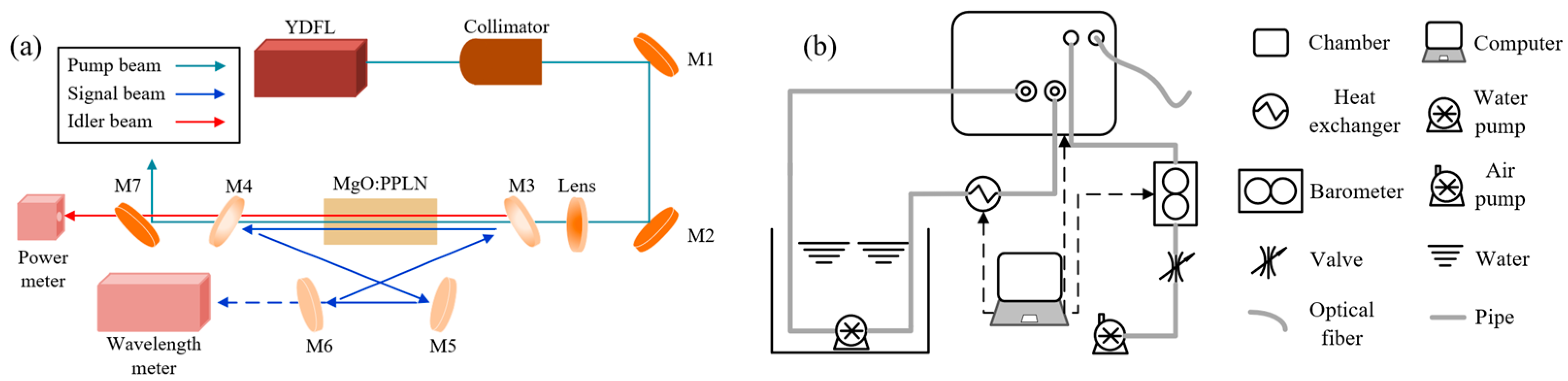
2. Experimental Setup

The experimental setup used was almost identical to the setups described previously [10,11,20]. As shown in Figure 1a, the seed source (EYP-DFB-1064, eagleyard Photonics GmbH, Berlin, Germany) with a ~2 MHz linewidth was a commercially available distributed feedback laser (DFB). The pump source was a linear-polarized cw Yb-doped fiber laser (YDFL) delivering a maximum of 23 W power at 1064.024 nm a with beam quality factor M2 < 1.1. The MgO:PPLN, as the nonlinear crystal, had dimensions of 50 × 10 × 1 mm3 and ten grating-periods ranging from 27.6 μm to 31.6 μm across its lateral dimension. Both the end faces of the crystal were antireflection-coated (T > 99%) at 1064 nm, 1400–2100 nm, and 2200–4400 nm. Two sapphire flakes were used to sandwich the crystal for even heating. They were housed in an oven with a stability of ±0.01 °C and mounted on a linear translation stage. M1,2 were highly reflecting at 1064 nm for an 45° angle of incidence. The ring cavity comprised two concave mirrors, M3,4 (the radius of curvature was −100 mm), and two plate mirrors, M5,6. The mirrors, M3–5, were highly reflecting (R > 99.8%) for the signal (1300–2100 nm), while M4, as the output coupler for the signal, was highly reflecting (R > 99.8%) for the ranges 1300–1600 nm and 1800–2100 nm, but had an output coupling of ~0.5% across 1600–1800 nm. In addition, M3–6 were highly transmitting (T > 99.5%) for the idler and pump. According to the length of the SRO cavity, the theoretical waist radius of the signal mode at the center of the crystal was estimated to be ~75 μm [30]. To match the mode of the signal beam, the pump beam, outputting through the fiber collimator, was focused to a spot with a waist of ~80 μm using a plano-concave lens. M7, as a dichroic mirror, was used to separate the output idler from the residual pump and leaking signal. The idler power and signal wavelength were monitored using a power meter (S425C, Thorlabs, Inc., New Jersey, United States) and a wavelength meter (WS6, HighFinesse GmbH, Tübingen, Germany), respectively. The shield of the SRO, i.e., an aluminum chamber with dimensions of 350 × 240 × 123 mm3, was used to erase disturbances in the air currents. As shown in Figure 1b, the base plate temperature of the chamber was stabilized within ±0.01 °C through water cooling equipped with a heat exchanger. The air pump sucked the air out through the valve, and the barometer recorded the air pressure in the chamber. The vent, the windows for the output laser, and the cover plate were all sealed with collar seals.

3. Results and Discussion

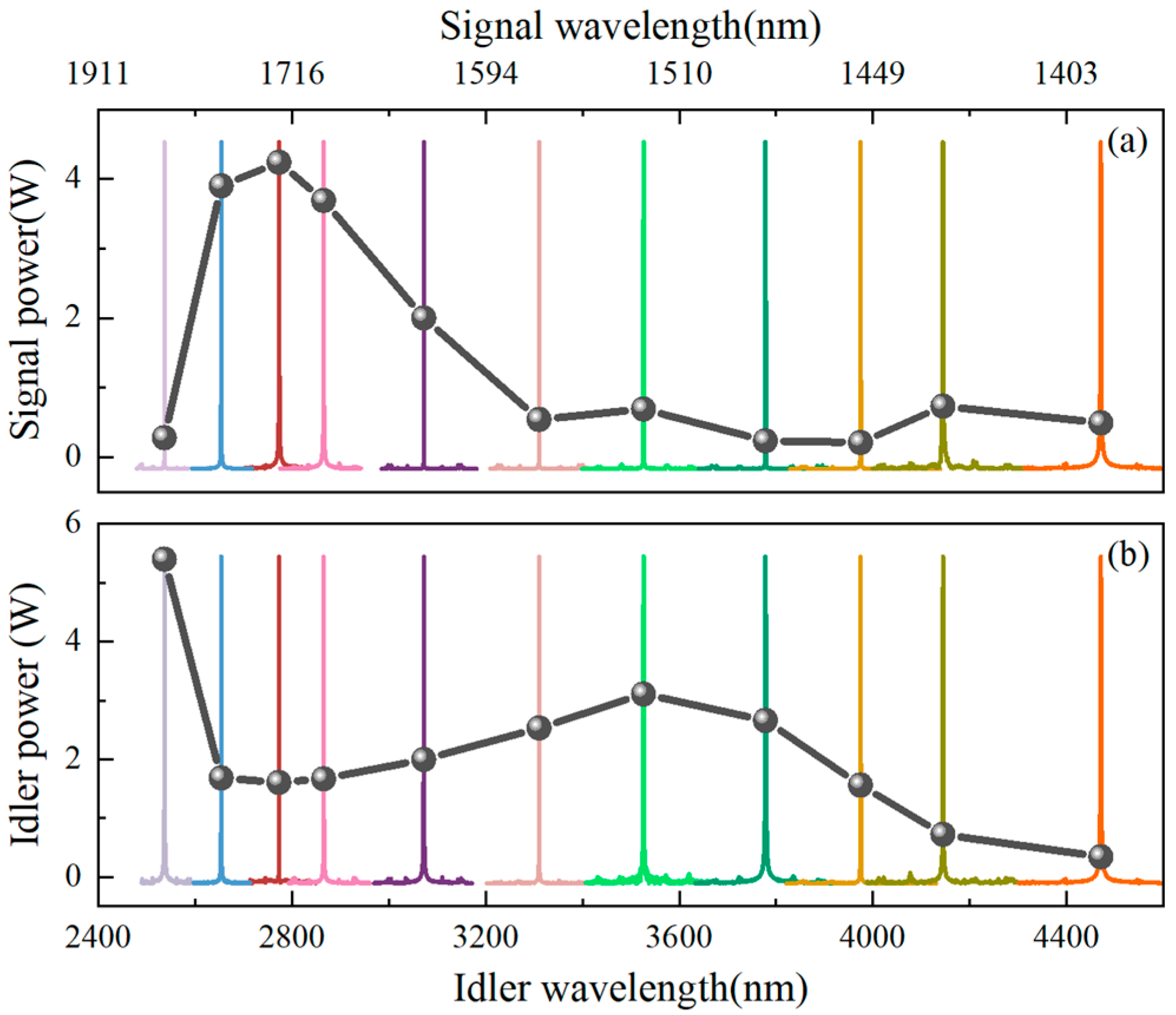
3.1. Emission Range and Output Power

Synchronizing the course-tuning of the crystal’s lateral translation with the fine-tuning of the crystal’s temperature enables the SRO to emit wide near- and mid-infrared radiation. As seen in Figure 2, each dotted line with a different color and symbol represents a crystal’s lateral translation, i.e., a poling period. The heating element obtains the temperature tuning of the oven across 35 °C to 210 °C. The whole range of the signal wavelength shown in the area below the breakpoint extends from 1450–1800 nm and the corresponding idler wavelength extends from 2450–4450 nm.
Figure 3 shows the spectrum of the output beam measured using a Fourier transform optical spectrum analyzer (OSA207, Thorlabs, Inc., New Jersey, United States). The solid curves were divided into eleven groups according to their color, with each group representing an idler spectrum and a corresponding signal spectrum. The dashed curve in Figure 3 shows the maximum output power of the extracted signal and idler across the tuning range when the pump power was ~23 W. As seen in Figure 3a, the signal power at the near wavelength of 1600 nm and 1800 nm sloped steeply due to the coating of M4. However, the corresponding idler power with beam quality factor M2 < 1.5, shown in Figure 3b, exhibited the opposite trend. The idler power of the wavelength beyond 4000 nm plummeted because material absorption became significant [21,31]. Over the whole tuning range, SRO could provide >200 mW of signal power with up to 4.2 W at a wavelength of 1726 nm, and >300 mW of idler power with up to 5.4 W at a wavelength of 2534 nm.

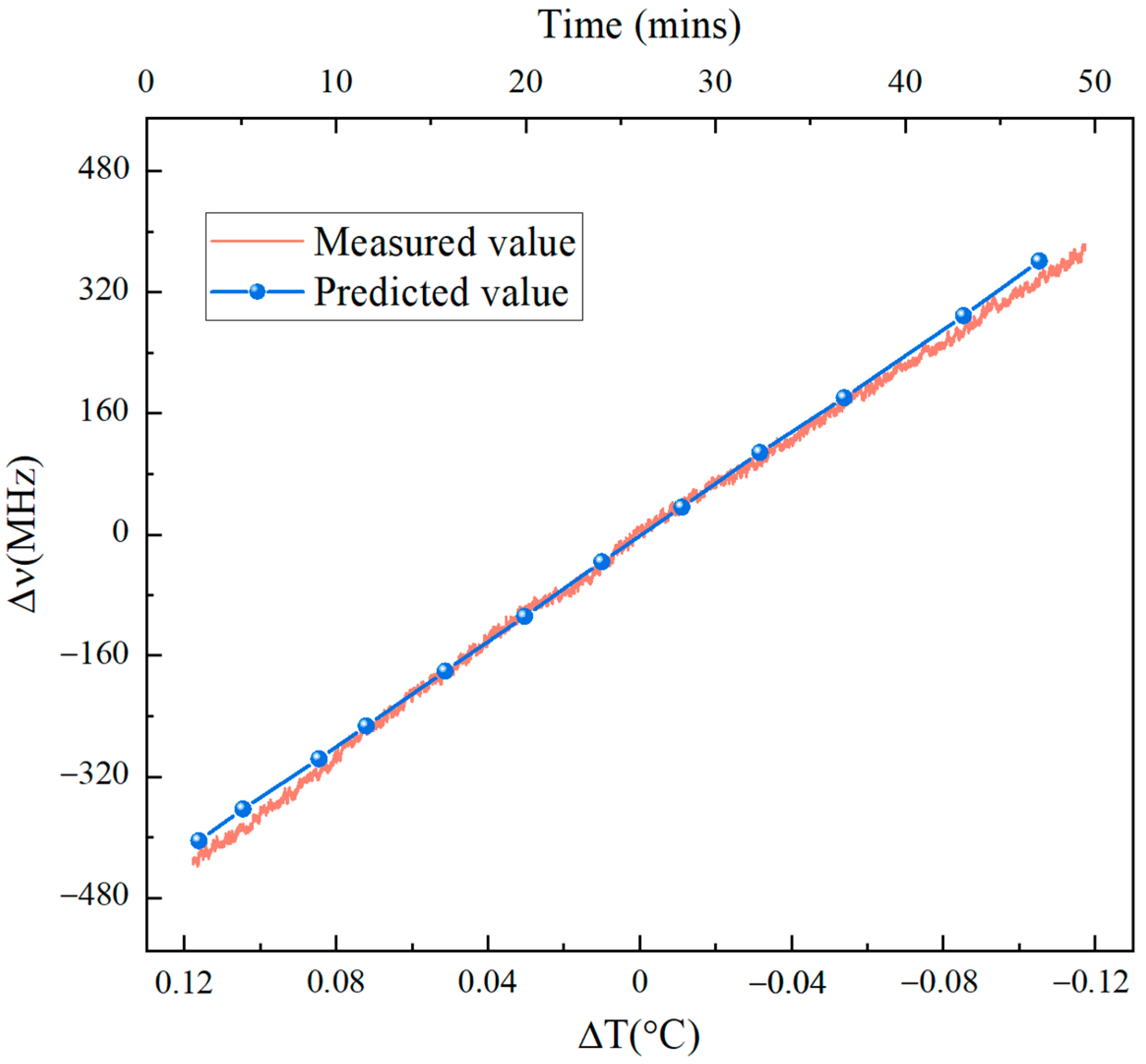
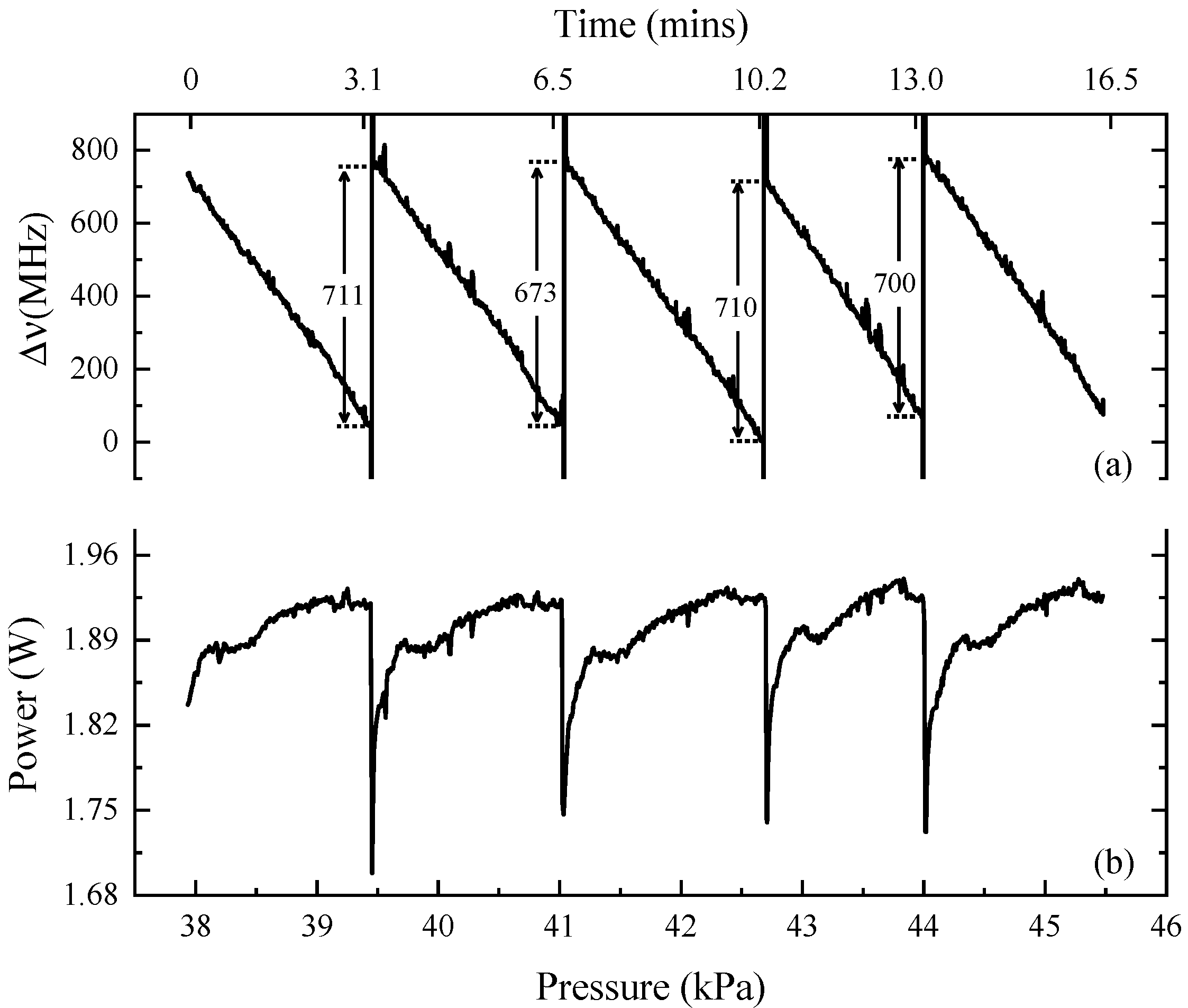
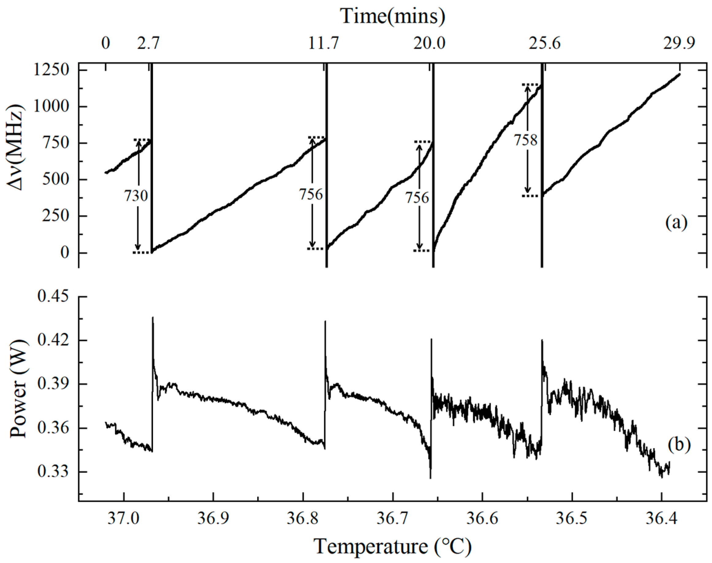
3.2. Parameters Affecting Frequency Shift

SRO’s idler wavelength was determined using pump wavelength and circling signal wavelength. Using the wavelength meter to measure the wavelength of the YDFL, a long-term frequency typically better than ± 25 MHz was observed over 5 h, which shows that the drift of the pump laser has a minor effect on the idler frequency shift. The resonant longitudinal mode was determined using the optical length of SRO, of which the thermal expansion has been thoroughly studied, while the air in the cavity is usually ignored. Here, we took into account the refractive index of the air in the chamber:
ν = N c l = N c n A L A + n C L C ,
where N is an integer number, l is the optical length, c is the speed of light, the subscripts A and C denote the paths of air and crystal, respectively, n is the refractive index, and L is the length, of each section in the two paths.
The frequency shift Δ ν introduced by a change in the refractive index of air Δ n A is given by the following relation:
Δ ν = ν L A n A L A +   n C L C Δ n A .
According to the equation for the refractivity of air [32], we obtain
Δ n = 0.0028426 n 1 S T Z Δ p ,
where ∆p is the air pressure variation, T is the temperature, Z is the compressibility factor, and n 1 S is the refractivity for standard air [33].
Using Equations (2) and (3), the frequency shift ∆ν can be calculated using the following relation:
Δ ν = 0 . 0028426 ν L A n 1 S n A L A + n C L C T Z Δ p .
By substituting the appropriate values of T (292.15 K), Z (0.9996), n A (1.000286), L A (380 mm), n C (2.14), L C (50 mm), and ν (205.31521 THz), the frequency shift Δ ν can be predicted by measuring the air pressure variation ∆p, which is shown as a dash–dot line in Figure 4. To validate the theoretical results, the aluminum chamber was evacuated. Then, we slowly injected air into it and constantly measured the air pressure and signal frequency. As seen in Figure 4, the frequency shift decreased from +155 MHz to −168 MHz over the air pressure variation range from −0.3 kPa to +0.3 kPa (the reference point of the pressure was 94.815 kPa), which was well in agreement with the predicted values. The frequency decreased at a rate of ~22 MHz/min, but fluctuated continually because of the air current.
Similarly, the frequency shift Δ ν introduced by the change in cavity length is given by the following relation:
Δ ν = ν n A n A L A + n C L C Δ L A ,
where Δ L A is the length variation of the base plate, which is determined from [34]:
Δ L A   = α L A Δ T ,
where α and Δ T represent, respectively, the thermal expansion coefficient and the base plate’s temperature change. The type of aluminum is 6061 and its thermal expansion coefficient is 24 × 10−6/K [34].
By substituting Equation (5) into Equation (6), we can obtain
Δ ν = ν α n A L A n A L A + n C L C Δ T .
By measuring the temperature change Δ T and substituting it into Equation (7), the predicted values of the frequency shift Δ ν from the center frequency of 191.31109 THz can be obtained. The results shown in Figure 5 are proportional to the temperature change. The solid line of Figure 5 shows that the measured frequency increased linearly with the temperature decrease when the aluminum chamber dissipated heat from 34.42 °C to 34.18 °C. Compared with the measured frequency in Figure 4, the violent fluctuation of the frequency could be controlled effectively using the airtight aluminum chamber.

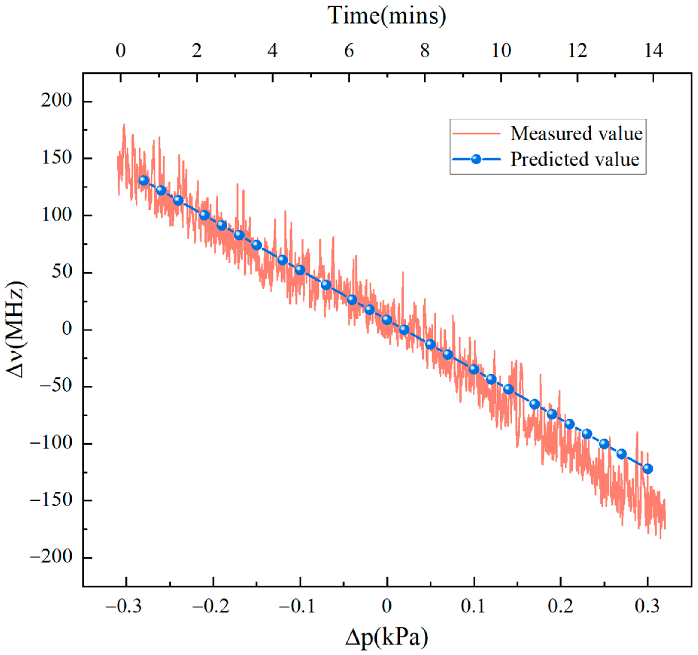
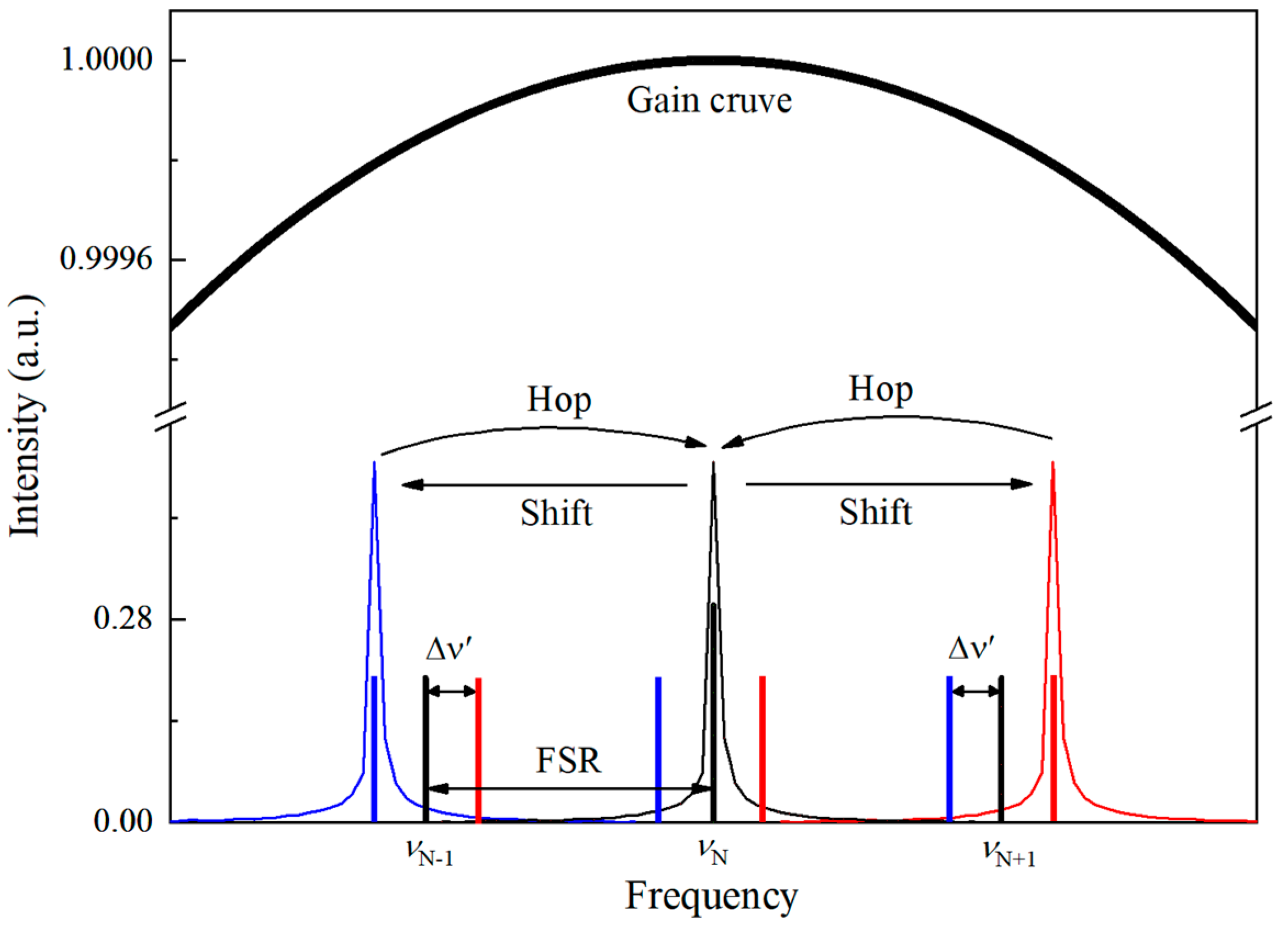
3.3. Mode Hops and Frequency Stability

The frequency no longer shifts linearly but suddenly switches to another frequency if the change in external influences, such as air pressure, is great enough. As shown in Figure 6a, the air pressure in the aluminum chamber gradually increased from 37.9 kPa to 45.5 kPa, which provoked a series of mode hops that varied like a sawtooth curve. The parallel dash lines indicate the ending of the previous mode and the beginning of the next mode, respectively. The distance between them indicates the frequency deviation in the two adjacent modes. Figure 6b shows the corresponding output power of idler while modulating mode hops. The idler power increased slowly to ~1.92 W with a frequency decrease but sharply reduced to minimum power while the cavity mode was hopping. Both the frequency drift of the signal and the idler power curves retraced their steps after each signal mode hop.
Longitudinal modes likewise may hop if the temperature of the base plate decreases even further, as shown in Figure 7a. During the heat dissipation of the whole aluminum chamber, the frequency made hops of >710 MHz four times in the temperature range from 37.02 °C to 36.40 °C. Noticeably, the deviation in frequency shift located in the temperature range from 36.66 °C to 36.53 °C was much larger than that in other regions due to thermal self-locking [21]. As seen in Figure 7b, the idler power variation as signal frequency changed was visible and increased by ~30% when the mode was hopping. The temperature of the base plate below 36.66 °C decreased at a much quicker pace than the previous part, which resulted in fiercer fluctuations of idler power.
According to Equation (1), the FSR of the SRO is ~620 MHz, which is much smaller than the spacing of the mode hops we measured in Figure 6 and Figure 7. We believe this is caused by the jump in signal and idler power at mode-hopping, which causes crystal refractive index variation through the laser heating effect. The mechanism for this is illustrated schematically in Figure 8. The broad curve and vertical lines indicate the parametric gain curve associated with QPM and longitudinal cavity modes related to the optical length, respectively. In the ideal case, the frequency ν N closest to the center of the gain curve is dominant over all other frequencies and will eventually oscillate. The decrease in the base plate temperature impels the frequency shift to ν N + 1 while not shifting the gain maximum until the frequency ν N + 1 has a higher gain and starts to oscillate. Compared to the initial state, however, the deviation in power ∆P can cause the temperature of the crystal along the optical path to shift slightly, and so does the refractive index of the crystal Δ n C . Thus, the oscillating cavity mode will hop back to the initial state until the frequency ν N shifts to ν N + 1 + Δ ν . (To distinguish the frequency shift mentioned in Figure 4, Figure 5, Figure 6 and Figure 7, Δ ν represents the extra frequency shift.) The deviation in frequency Δ ν obtained from Equation (1) is
Δ ν = ν L C n A L A + n C L C Δ n C .
Specifically, the experimentally observed power drop was ~0.08 W, shown in Figure 7, between two modes, which resulted in a frequency shift Δ ν increment of as small as 130 MHz, corresponding to the temperature decrement of ~0.15 °C. If power increases, as shown in Figure 6, the deviation in power will cause a blue-shift, so the modes hop at ν N 1 Δ ν .
To characterize the performance of the SRO, we examined the long-term stability of the signal frequency at 1511.814 nm and the corresponding idler power under free-running conditions for a pump power of ~15 W. As can be seen in Figure 9, the SRO was capable of operating without mode hops over 13 h after stabilization of the temperature of the crystal and base plate. However, its frequency fluctuated periodically because of the influence of the air conditioner. Specifically, the deviation in the signal frequency was ± 400 MHz and the root meat square (RMS) of the idler power was 2.55%. To further improve the frequency and power stability, it is necessary to avoid air temperature changes caused by air conditioning. Similar to the results in Figure 6 and Figure 7, the signal frequency and idler power trends were opposite.

4. Conclusions

In summary, we built an airtight SRO capable of a wide tunning range at the near- and mid-infrared ranges and presented a comprehensive analysis of its frequency stability. Over small air pressure changes, the frequency shift can be adjusted linearly, which provides a simple way of conducting high-precision frequency tuning. However, frequency tuning is inevitably accompanied by fluctuation due to airflow. Fortunately, the fluctuation can be avoided using another method, i.e., base plate temperature. An analysis of subtle ambient perturbations affecting frequency shift is essential for passive frequency stabilization of cw OPO and promotes better commercialization of OPOs with active stabilizations and monolithic structures. In addition, thermal-induced refractive index variation in crystals also affects frequency shift. To monitor this, we artificially provoked the operational frequency to hop to an adjacent longitudinal mode and recorded the signal frequency and idler output power. The difference of ~120 MHz between the spacing of the hops and FSR was obtained. This means that the temperature deviation was ~0.15 °C due to local absorption of the optical power. When controlling frequency stability, the laser-induced heating cannot be ignored, or additional frequency variations will be induced by laser power fluctuation. By carefully sealing the cavity and stabilizing the temperature, the free-running SRO was made passively stable against acoustic vibrations and it operated without mode hops over the whole night. However, the frequency fluctuated due to airflow inside and outside the cavity. A vacuum cavity may ameliorate such fluctuations.

Author Contributions

Conceptualization, X.L.; methodology, X.L. and J.N.; validation, L.H. and Y.H.; formal analysis, L.H., X.L. and J.N.; investigation, X.L., G.Z. and S.Z.; data curation, L.H. and Y.H.; writing—original draft preparation, L.H. and Y.H.; writing—review and editing, X.L. and J.N.; funding acquisition, X.L. and J.N. All authors have read and agreed to the published version of the manuscript.

Funding

This research was funded by the National Natural Science Foundation of China (Grant No.12192251) and the National Postdoctoral Program for Innovative Talents (BX201700117).

Institutional Review Board Statement

Not applicable.

Informed Consent Statement

Not applicable.

Data Availability Statement

The data underlying the results presented in this paper are not publicly available at this time but may be obtained from the authors upon reasonable request.

Conflicts of Interest

The authors declare no conflict of interest.

References

  1. De Escobar, Y.N.M.; Mickelson, P.G.; Pellegrini, P.; Nagel, S.B.; Traverso, A.; Yan, M.; Cote, R.; Killian, T.C. Two-photon photoassociative spectroscopy of ultracold Sr-88. Phys. Rev. A 2008, 78, 062708. [Google Scholar] [CrossRef] [Green Version]
  2. Tittel, F.K.; Richter, D.; Fried, A. Mid-Infrared Laser Applications in Spectroscopy; Springer: Berlin/Heidelberg, Germany, 2003; pp. 458–529. [Google Scholar]
  3. Seiter, M.; Sigrist, M.W. Trace-gas sensor based on mid-IR difference-frequency generation in PPLN with saturated output power. Infrared Phys. Technol. 2000, 41, 259–269. [Google Scholar] [CrossRef]
  4. Dunn, M.H.; Ebrahimzadeh, M. Parametric generation of tunable light from continuous-wave to femtosecond pulses. Science 1999, 286, 1513–1517. [Google Scholar] [CrossRef]
  5. Lindsay, I.D.; Petridis, C.; Dunn, M.H.; Ebrahimzadeh, M. Continuous-wave pump-enhanced singly resonant optical parametric oscillator pumped by an extended-cavity diode laser. Appl. Phys. Lett. 2001, 78, 871–873. [Google Scholar] [CrossRef]
  6. Henderson, A.J.; Roper, P.M.; Borschowa, L.A.; Mead, R.D. Stable, continuously tunable operation of a diode-pumped doubly resonant optical parametric oscillator. Opt. Lett. 2000, 25, 1264–1266. [Google Scholar] [CrossRef] [PubMed]
  7. Siltanen, M.; Vainio, M.; Halonen, L. Pump-tunable continuous-wave singly resonant optical parametric oscillator from 2.5 to 4.4 μm. Opt. Express 2010, 18, 14087–14092. [Google Scholar] [CrossRef] [PubMed]
  8. Zhang, Y.C.; Duan, Y.M.; Wang, Z.G.; Zhang, D.; Zhang, J.; Zhang, Y.J.; Zhu, H.Y. Continuous-Wave Widely Tunable MgO:PPLN Optical Parametric Oscillator With Compact Linear Cavity. IEEE Photonics Technol. Lett. 2018, 30, 1756–1759. [Google Scholar] [CrossRef]
  9. Van Herpen, M.; Bisson, S.E.; Harren, F.J.M. Continuous-wave operation of a single-frequency optical parametric oscillator at 4–5 μm based on periodically poled LiNbO3. Opt. Lett. 2003, 28, 2497–2499. [Google Scholar] [CrossRef]
  10. Bosenberg, W.R.; Drobshoff, A.; Alexander, J.I.; Myers, L.E.; Byer, R.L. 93% pump depletion, 3.5-W continuous-wave, singly resonant optical parametric oscillator. Opt. Lett. 1996, 21, 1336–1338. [Google Scholar] [CrossRef] [Green Version]
  11. Liu, Y.C.; Xie, X.K.; Ning, J.; Lv, X.J.; Zhao, G.; Xie, Z.D.; Zhu, S.N. A High-Power Continuous-Wave Mid-Infrared Optical Parametric Oscillator Module. Appl. Sci. 2018, 8, 1. [Google Scholar] [CrossRef]
  12. Shukla, M.K.; Das, R. High-Power Single-Frequency Source in the Mid-Infrared Using a Singly Resonant Optical Parametric Oscillator Pumped by Yb-Fiber Laser. IEEE J. Sel. Top. Quantum Electron. 2018, 24, 1–6. [Google Scholar] [CrossRef]
  13. Radiant Light S.L. Homepage. Available online: https://radiantis.com/products/titan-cw-opo-based-laser-system/ (accessed on 10 December 2022).
  14. Van Herpen, M.; Bisson, S.E.; Ngai, A.K.Y.; Harren, F.J.M. Combined wide pump tuning and high power of a continuous-wave, singly resonant optical parametric oscillator. Appl. Phys. B-Lasers Opt. 2004, 78, 281–286. [Google Scholar] [CrossRef]
  15. Vainio, M.; Siltanen, M.; Peltola, J.; Halonen, L. Grating-cavity continuous-wave optical parametric oscillators for high-resolution mid-infrared spectroscopy. Appl. Opt. 2011, 50, A1–A10. [Google Scholar] [CrossRef] [PubMed]
  16. Von Basum, G.; Halmer, D.; Hering, P.; Murtz, M.; Schiller, S.; Muller, F.; Popp, A.; Kuhnemann, F. Parts per trillion sensitivity for ethane in air with an optical parametric oscillator cavity leak-out spectrometer. Opt. Lett. 2004, 29, 797–799. [Google Scholar] [CrossRef] [PubMed] [Green Version]
  17. Al-Tahtamouni, R.; Bencheikh, K.; Storz, R.; Schneider, K.; Lang, M.; Mlynek, J.; Schiller, S. Long-term stable operation and absolute frequency stabilization of a doubly resonant parametric oscillator. Appl. Phys. B-Lasers Opt. 1998, 66, 733–739. [Google Scholar] [CrossRef]
  18. Li, P.; Li, Y.; Feng, J.; Zhang, K. Theoretical and experimental investigation of singly resonant optical parametric oscillator under double-pass pumping. Appl. Opt. 2015, 54, 4374–4379. [Google Scholar] [CrossRef] [PubMed] [Green Version]
  19. Ikegami, T.; Slyusarev, S.; Ohshima, S.I. Long-term, mode-hop-free operation of a continuous-wave, doubly resonant, monolithic optical parametric oscillator. Opt. Commun. 2000, 184, 13–17. [Google Scholar] [CrossRef]
  20. Vainio, M.; Peltola, J.; Persijn, S.; Harren, F.J.M.; Halonen, L. Singly resonant cw OPO with simple wavelength tuning. Opt. Express 2008, 16, 11141–11146. [Google Scholar] [CrossRef] [Green Version]
  21. Vainio, M.; Peltola, J.; Persijn, S.; Harren, F.J.M.; Halonen, L. Thermal effects in singly resonant continuous-wave optical parametric oscillators. Appl. Phys. B-Lasers Opt. 2009, 94, 411–427. [Google Scholar] [CrossRef]
  22. Henderson, A.; Stafford, R. Intra-cavity power effects in singly resonant cw OPOs. Appl. Phys. B-Lasers Opt. 2006, 85, 181–184. [Google Scholar] [CrossRef]
  23. Zheng, X.H.; He, G.Y.; Zhang, B.F.; Guo, J.; Jiao, Z.X.; Wang, B.A. Joint Thermal Effects of VBG and Nonlinear Crystal in a Singly Resonant OPO. IEEE Photonics Technol. Lett. 2016, 28, 1107–1110. [Google Scholar] [CrossRef]
  24. Lin, D.; Shaif-ul, A.; Shen, Y.H.; Chen, T.; Wu, B.; Richardson, D.J. Large aperture PPMgLN based high-power optical parametric oscillator at 3.8 μm pumped by a nanosecond linearly polarized fiber MOPA. Opt. Express 2012, 20, 15008–15014. [Google Scholar] [CrossRef] [PubMed] [Green Version]
  25. Moore, R.O.; Biondini, G.; Kath, W.L. Self-induced thermal effects and modal competition in continuous-wave optical parametric oscillators. J. Opt. Soc. Am. B-Opt. Phys. 2002, 19, 802–811. [Google Scholar] [CrossRef]
  26. Khabbaz, M.; Sabaeian, M.; Nadgaran, H. Heat-coupled Gaussian continuous-wave double-pass optical parametric oscillator: Thermally induced phase mismatching for periodically poled MgO:LiNbO3 crystal. Appl. Opt. 2017, 56, 6419–6426. [Google Scholar] [CrossRef]
  27. Hutcheon, R.J.; Perrett, B.J.; Mason, P.D. Modelling of Thermal Effects within a 2 μm Pumped ZGP Optical Parametric Oscillator Operating in the Mid-Infrared. In Proceedings of the Conference on Solid State Laser Technologies and Femtosecond Phenomena, London, UK, 25–27 October 2004; pp. 264–274. [Google Scholar]
  28. Lin, S.T.; Lin, Y.Y.; Huang, Y.C.; Chiang, A.C.; Shy, J.T. Observation of thermal-induced optical guiding and bistability in a mid-IR continuous-wave, singly resonant optical parametric oscillator. Opt. Lett. 2008, 33, 2338–2340. [Google Scholar] [CrossRef] [Green Version]
  29. Ivanov, G.Y.; Cherpak, P.S.; Konyashkin, A.V.; Ryabushkin, O.A. Accurate measurements of longitudinal temperature distribution of PPLN crystal in the process of second-harmonic generation. Appl. Opt. 2020, 59, 7330–7337. [Google Scholar] [CrossRef]
  30. Davis, C.C. Lasers and Electro-Optics: Fundamentals and Engineering, 2nd ed.; Cambridge University Press: Cambridge, UK, 2014. [Google Scholar]
  31. Niu, Y.R.; Yan, X.; Chen, J.X.; Ma, Y.X.; Zhou, Y.D.; Chen, H.; Wu, Y.; Bai, Z.X. Research progress on periodically poled lithium niobate for nonlinear frequency conversion. Infrared Phys. Technol. 2022, 125, 104243. [Google Scholar] [CrossRef]
  32. Jones, F.E. The Refractivity of Air. J. Res. Nat. Bur. Stand. 1981, 86, 27–32. [Google Scholar] [CrossRef]
  33. Peck, E.R.; Reeder, K. Dispersion of Air. J. Opt. Soc. Am. 1972, 62, 958–962. [Google Scholar] [CrossRef]
  34. Cverna, F. ASM Ready Reference: Thermal Properties of Metals; ASM International: Almere, The Netherlands, 2002; p. 560. [Google Scholar]
Figure 1. (a) Experimental setup for four-mirror ring cavity and (b) experimental setup for water cooling and pressure controlling.
Photonics 10 00005 g001
Figure 2. Wavelength tuning of the idler beam and signal beam.
Photonics 10 00005 g002
Figure 3. Output power (dashed curve) and corresponding spectrum (solid curve) of (a) signal beam and (b) idler beam.
Photonics 10 00005 g003
Figure 4. Measured and theoretical deviation in signal frequency as a function of air pressure shift.
Photonics 10 00005 g004
Figure 5. Measured and theoretical deviation in signal frequency as a function of temperature shift.
Photonics 10 00005 g005
Figure 6. (a) Mode hops of signal beam provoked by air pressure and (b) corresponding idler power. The reference point of the frequency is 198.23992 THz.
Photonics 10 00005 g006
Figure 7. (a) Mode hops of signal beam provoked by the temperature of the base plate and (b) corresponding idler power. The reference point of the frequency is 201.71606 THz.
Photonics 10 00005 g007
Figure 8. Principle of mode hop in a working SRO.
Photonics 10 00005 g008
Figure 9. Measured signal frequency (a) and idler power (b) stability over 13 h.
Photonics 10 00005 g009
Disclaimer/Publisher’s Note: The statements, opinions and data contained in all publications are solely those of the individual author(s) and contributor(s) and not of MDPI and/or the editor(s). MDPI and/or the editor(s) disclaim responsibility for any injury to people or property resulting from any ideas, methods, instructions or products referred to in the content.

