1. Introduction
The development of relatively cheap and miniature (on the order of a few centimeters or less) gyroscopes for a wide range of applications is one of the most important tasks in the development of orientation and navigation devices. Today, this niche is occupied by various types of micromechanical inertial angular velocity sensors, which owe their appearance, first of all, to success in the development of microelectromechanical technologies. Compared to other types of sensors, they have low weight, overall dimensions, and power consumption. At the same time, the sensitivity of the best micromechanical sensors is at least two orders of magnitude lower than the sensitivity of optical sensors. There are also disadvantages due to the specifics of the sensitive element of micromechanical sensors. As sensitive elements, inertial masses fixed in an elastic suspension are used, which, when the sensor is turned on, are set into oscillatory motion [
1,
2,
3,
4]. As a result, such sensors have a relatively long readiness time (up to several seconds), have cross-links when building a three-axis block of sensitive elements and are sensitive to linear accelerations and various types of mechanical influences (shocks, vibrations), which limits their possible scope. Of course, to date, various methods have been developed to improve the resistance of such sensors to shocks and vibrations, which include, for example, filling micromechanical sensors with a protective compound, temporarily turning off sensors during peak loads, etc. [
5,
6,
7,
8]. However, this significantly reduces the characteristics of the sensors, limits their possible areas of application, and at the same time, the fundamental sensitivity to shocks and vibrations due to the presence of moving parts is preserved.
Optical (laser and fiber optic) gyroscopes do not have these shortcomings. However, they usually cannot be used in navigation systems to control compact portable vehicles due to their relatively large size and weight. Therefore, today, the task of the miniaturization of optical gyroscopes and the development of microoptical gyroscopes (MOGs) is relevant. There are several ways to solve this problem [
9,
10,
11]. At the same time, they usually focus on (strive to achieve) a range of accuracy in measuring the angular velocity of 0.1–10°/h. Possible applications of such gyroscopes are usually positioned, such as aerospace and the management of compact objects, which are characterized by working in conditions of high overloads [
11]. The most promising is the construction of compact optical resonator gyroscopes. The sensitive element, in this case, is a passive ring resonator, the natural frequencies of which are split during rotation due to the Sagnac effect. The natural frequency difference, proportional to the rotation speed, is determined by scanning the resonator in frequency. Frequency scanning is usually performed by tunable lasers with a built-in frequency stabilization system [
12,
13,
14]. Such lasers are comparatively bulky, which hinders the miniaturization of optical gyroscopes.
It is worth noting that the use of phase modulation spectroscopy generally eliminates the need for a tunable laser. At the same time, the frequencies of two waves bypassing the resonator in opposite directions (along and against the arrow) change due to the use of two systems consisting of several phase and/or frequency modulators [
15,
16,
17]. However, in this case, non-reciprocal configurations are used—two counter waves pass through different modulator systems. This further complicates the design of the device, and when the temperature and other environmental parameters change, the dynamics of the characteristics of the two systems are different, which can cause additional errors in measurement and makes the device less stable. In addition, when using phase modulation spectroscopy, lasers with a tunable frequency are also often used as a source, for example, to adjust the frequency of radiation of one of the waves to the eigenfrequency of the resonator [
16,
17].
In this work, we consider a different approach to the construction and principle of operation of an optical resonator gyroscope. This approach does not require frequency scanning of the passive ring resonator and is implemented by using a Mach–Zehnder modulator with a passive ring resonator connected to one of its arms. This makes it possible to obtain a mutual configuration and makes it unnecessary to use a tunable laser. Almost any type of ring resonator (fiber optic, integrated optical, whispering gallery mode, etc.) can be used as a sensitive element. To study the proposed approach, it was decided to implement the experimental setup of the gyroscope and its sensitive elements on a fiber-optic base. This work is primarily devoted to the study of a new approach to the construction of an optical resonator gyroscope. Previously, this approach was analyzed purely theoretically. Within the framework of this study, the first experiment was carried out to test the proposed approach in practice. At the same time, there was no goal to achieve or approach the maximum sensitivity of the method or to the most accurate of the existing prototypes of optical resonator gyroscopes.
2. Method for Measuring the Rotation Speed by an Optical Resonator Gyroscope with a Mach–Zehnder Modulator
For clarity, let us consider the method of measuring the rotation speed on the example of a simplified circuit of the device that implements it (
Figure 1).
The radiation from the laser, 1, enters the optical splitter, 2, and is divided into two channels—CCW (counterclockwise channel) and CW (clockwise channel). Then the radiation in each of the channels is directed through circulators, 3 and 4, to the inputs of the Mach–Zehnder modulator. The Mach–Zehnder modulator is composed of optical splitters, 8 and 9, and a phase modulator, 7. Next, a passive ring resonator, 10, is connected to one of the arms of the interferometer, which is a closed waveguide optically coupled to the auxiliary waveguide. As a result, the radiation of the CCW channel is fed into the ring resonator in a counterclockwise direction, and the radiation of the CW channel, is in a clockwise direction. After passing through the Mach–Zehnder modulator, the radiation powers
PoutCW and
PoutCCW through the circulators, 3 and 4, and is sent to the photodetectors, 5 and 6, respectively. Let us say all optical splitters, 2, 8, and 9, have a division ratio of 50/50. In this case, the radiation powers
PoutCW and
PoutCCW are equal:
PinCCW =
PinCW =
Pin—radiation power at the input of the CCW and CW channels; δ
FM—phase shift created by the modulator, 7;
TCCW и
TCW—transfer characteristics of the resonator, 10, in terms of radiation power (equal to the square of the modulus of expression, 3); ΔΦ
CW and ΔΦ
CCW—phase characteristics of the resonator, 10 (equal to the argument of expression, 3).
where:
δ
CCW, CW—phase shift during a single round trip of the ring resonator by the wave (in CCW and CW directions);
P is the fraction of power lost by the wave in one bypass of the passive ring resonator;
Kc is the energy coefficient of the coupling of the auxiliary waveguide resonator with a ring one;
Lop is the optical length of the resonator;
f is the frequency of optical radiation;
c is the speed of light propagation in a vacuum;
fS is the difference between the natural frequencies of the passive ring resonator for opposite directions of its bypass (CW and CCW), caused by the Sagnac effect;
A is the area covered by the ring resonator; λ
0 is the wavelength of light in a vacuum in the absence of rotation; Ω is the angular velocity of the passive ring resonator during rotation about the axis perpendicular to the resonator plane.
With a sawtooth law of change in δ
FM on the modulator, in accordance with expressions 1–7, the radiation power incident on the photodetectors will change according to the harmonic law.
Figure 2 illustrates this for the photodetector, 5, with a ring resonator radius of 10 mm,
Kc = 0.05, and
P = 0.025.
From expressions 1–7 and
Figure 2, it is obvious that the amplitude of the normalized harmonic signal,
S, on photodetectors and/or its phase Φ (phase shift relative to the sawtooth signal of the modulator) can act as a measure of the angular velocity. From expressions 1 and 2:
a and
b—splits in which splitters, 8 and 9, separate the wave (in the case considered above, a = b = 0.5).
S or Φ can be determined in various ways, for example, using the Fourier transform of signals from photodetectors. Using expressions 6 and 7, it is easy to express the angular velocity in terms of the difference in phase incursions during a single circumvent of the ring resonator by a wave Δδ:
This makes it possible to get rid of the influence of mutual effects on the measurement results, for example, temperature instability of the radiation frequency of the light source. Moreover, when used as a measure of the angular velocity S, the difference of the phase incursions Δδ is expressed in terms of the square of the modulus of expression 3 and using expression (8):
Similarly, Φ can be used as a measure of angular velocity. A more detailed theoretical consideration of this method is given in previous articles on this topic [
18,
19].
It should be noted that before the experimental implementation of the described method for measuring the angular velocity, it is necessary to determine such resonator characteristics as
P,
Kc, and
Lop. The current study uses fiber optic ring resonators obtained from X-shaped optical splitters. Therefore, the value of
Kc is considered to be known a priori (determined at the stage of manufacturing the splitter). The values of
P and
Lop can be easily determined empirically from the frequency response of the resonator. In particular,
Lop can be calculated from the FSR (Free Spectral Range):
The value of
P can be expressed in terms of
Kc and also determined from the resonator spectrum by FSR and FWHM (full width at half maximum). When determining
P, for simplicity, we assume that the resonator is stationary, i.e.,
fS = 0 and
TCCW =
TCW =
T (when rotating, the result will be identical). It is obvious from the definition of FWHM that:
where δ
FWHM = 2π × FWHM/FSR is the phase-shifted value of full width at half maximum. As noted above, T corresponds to the square of the modulus of expression 3. Using this fact, the following can be obtained from expression (12):
Substituting expressions (4) and (5) into (13), we can express the value of
P:
In expression (14), the fraction of power lost by a wave in one bypass of a passive ring resonator corresponds only to
P2. The value of
P1 is negative and corresponds to similar parameters, but an active resonator, when bypassing which, on the contrary, an amplification is observed. In the framework of this work, only
P =
P2 was of interest. In particular, it is used to assess the limiting sensitivity of the proposed method of measuring angular velocity (the smallest change in angular velocity that can be measured in principle against a background of noise) [
19]:
where
h is Planck’s constant; Δ
ν is the bandwidth of the signal processing system.
3. Experiment
Within the framework of this study, two fiber-optic ring resonators were fabricated. They were obtained using X-shaped optical couplers made of polarization-maintaining fiber-type PANDA. The fiber that forms the resonators supports the propagation of two polarization modes. The resonator coupling coefficients
Kc are the same for both polarization modes and are equal to 0.1 for the first resonator and 0.05 for the second. It should be noted that their integrated optical configurations are now more promising as sensitive elements of optical resonator gyroscopes [
20]. Fiber resonators are used as a more easily accessible and flexible (from the point of view of circuit restructuring) version of the sensing element. The resonators were made of polarization-maintaining fiber in order to reduce the error caused by polarization fluctuations [
21]. Of course, the use of a photonic crystal fiber with a hollow core is more promising, which also makes it possible to reduce the influence of the optical Kerr effect [
22,
23]. However, within the framework of this work, it was not possible to achieve or approach the maximum sensitivity of the method, and secondly, PANDA is more technologically advanced (for example, it is better welded). Therefore, it was used when creating resonators.
To analyze the characteristics of the resonators, an experimental setup, which is shown in
Figure 3, was assembled. It consists of a semiconductor laser, 1, a fiber-optic splitter, 2, an auxiliary Mach–Zehnder interferometer, 3, photodetectors, 4 and 10, a fiber-optic tunable attenuator, 6, a fiber optic polarization controller, 7, an optical radiation polarization state analyzer, 8, a fiber optic ring resonator, 9, and an oscilloscope, 5.
Examples of signals taken from photodetectors are shown in
Figure 4 (taken during the study of the first resonator). The graphs in
Figure 4 are normalized with respect to the maximum value of the recorded signal.
Figure 4a,b show the signal from a photodetector connected to a ring resonator, and
Figure 4c,d show a signal from a photodetector connected to an auxiliary Mach–Zehnder interferometer, 3. An auxiliary Mach–Zehnder interferometer, 3, was used to determine the change in the radiation frequency of the laser, 1. To do this, an optical delay line was introduced into one of the arms of the Mach–Zehnder interferometer, 3. As a result, at each count (or at each moment of time), the phase shift of the signal from the photodetector, 4, is proportional to the change in the frequency of radiation from the laser, 1, which was used to determine the frequency characteristics of the resonators (
Figure 5).
Similar measurements were made many times and also performed for another polarization mode and the second fiber optic resonator. As a result, the frequency characteristics of the resonators were built (their example is shown in
Figure 5), from which FWHM, FSR,
Lop, and
P were determined using expressions (9) and (10). The quality factors of the resonators
Q =
f/FWHM were also determined. The listed characteristics of ring resonators are given in
Table 1.
Further, in
Figure 5, the experimentally obtained frequency response of mode 1 of the first resonator is superimposed with its analytical response obtained by substituting
Kc,
P, and
Lop into expression 3. The characteristics coincided with the noise component. This justifies the further use of the obtained resonator characteristics in the method of measuring angular velocity.
Using expression 15, the limiting sensitivity of the proposed method was evaluated when using the described resonators. At Pin = 2.5 mW and Δν = 1 Hz, it was 3.2 °/h for the first and 1.8 °/h for the second resonator.
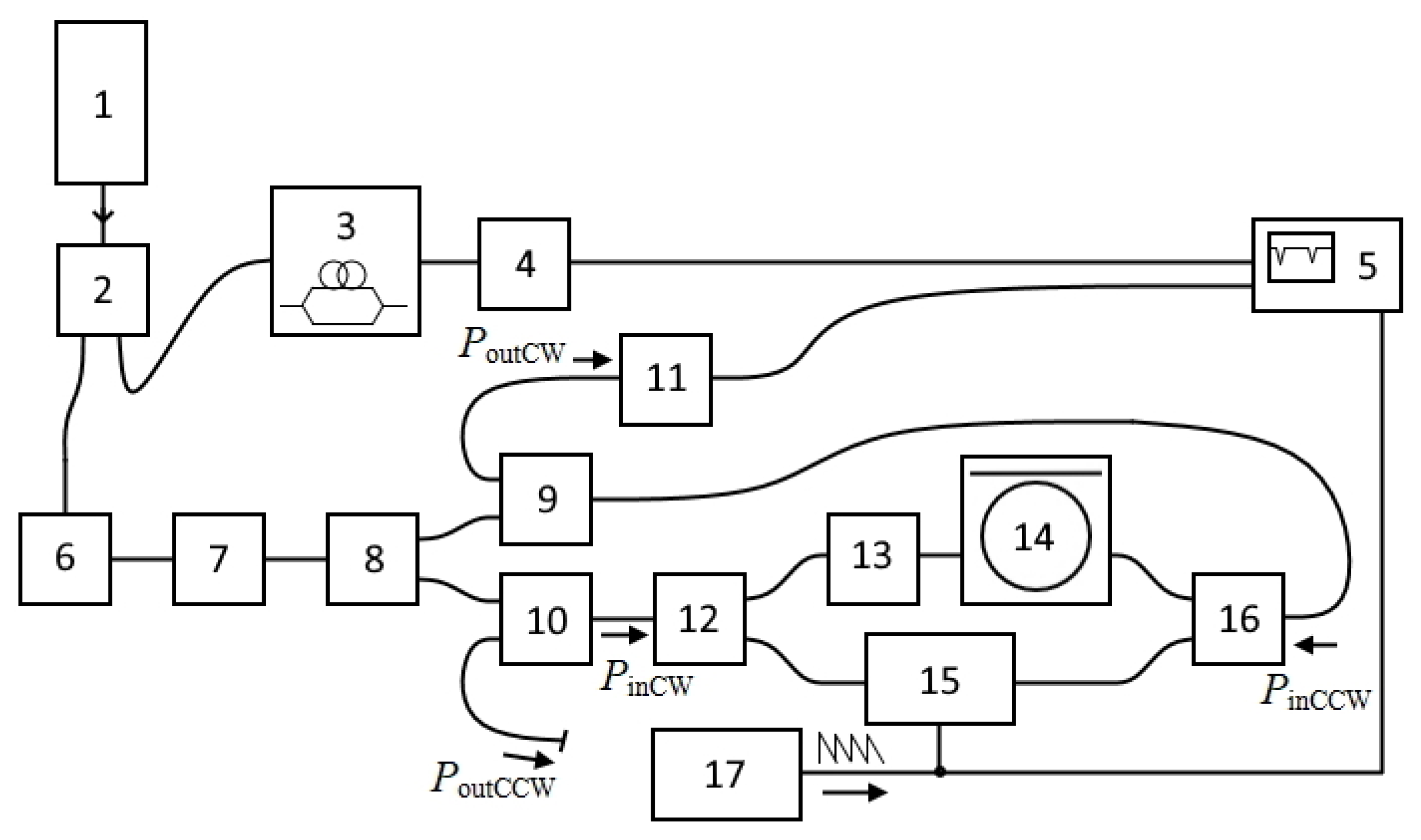
Further, using the first resonator, an experimental version of an optical resonator gyroscope with a Mach–Zehnder modulator was assembled (
Figure 6). It consisted of a semiconductor laser, 1, fiber-optic splitters, 2, 8, 12, and 16, circulators, 9 and 10, an auxiliary Mach–Zehnder interferometer, 3, photodetectors, 4 and 11, an oscilloscope, 5, a fiber-optic polarization controller, 6, an optical radiation polarization state analyzer, 7, a fiber-optic tunable attenuator, 13, a fiber-optic ring resonator, 14, a phase modulator, 15, and a sawtooth signal generator, 17. Thus, as required by the measurement method, the resonator, 14, was included in one of the arms of the Mach–Zehnder modulator, formed by elements 12–16.
It should be noted that the phase modulator, 15, used in the creation of the setup introduced significant losses (more than 20 dB) into one of the arms of the Mach–Zehnder interferometer. To equalize the radiation power, an attenuator, 13, had to be introduced into the second arm of the Mach–Zehnder interferometer. As a result, the optical Kerr effect in the resonator exceeded the Sagnac effect, which did not allow direct measurement of the rotation speed using the described setup. In this regard, in order to experimentally determine the sensitivity of the setup, the stabilization of radiation frequency in the laser, 1, was turned off. The frequency of its radiation changed, which, using only one of the measuring channels, in accordance with expression 6, made it possible to simulate a change in the rotation speed and determine the characteristics of the experimental setup. Therefore, only the CW channel was used in the experiment (only PoutCW was analyzed).
Examples of signals fed to the oscilloscope are shown in
Figure 7. Signals from the photodetectors are normalized. The graphs in
Figure 7a,b,d are normalized with respect to the maximum value of the recorded signal. The sawtooth signal shown in
Figure 7c was generated at a frequency of 300 Hz. The signal from the auxiliary Mach–Zehnder interferometer, 3, was used to determine the change in the frequency of the laser radiation, 1.
Figure 7a shows the signal from the output of the CW channel. As noted in Chapter 2, its amplitude S or its phase Φ can act as a measure of angular velocity.
At the same time, the accuracy of measuring the angular velocity δΩ of the experimental setup can be estimated from the noise of the parameter used as a measure of the angular velocity δ
X:
where either
S or Φ acts as
X. Using the signals taken from the photodetectors and the signal generator, using the Fourier transform, and expressions 3–10, the noises
S and Φ are determined, as well as the average values for the measurement range d
S/dΩ and dΦ/dΩ. When measuring the quasi-harmonic signal and its phase, the measurement accuracy was approximately 11 °/s and 0.4 °/s, respectively.
4. Discussion
This work is devoted, first of all, to the study of a new approach to the construction of an optical resonator gyroscope. It is realized by using a Mach–Zehnder modulator with a passive ring resonator connected to one of its shoulders. Previously, this approach was analyzed purely theoretically. The first experiment was carried out to test the proposed approach in practice. At the same time, there was no goal to achieve or approach the extreme sensitivity of the method or the most accurate of the existing prototypes of optical resonator gyroscopes.
The maximum sensitivity of the proposed method when using the first resonator is 3.2 °/h, and when using the second, 1.8 °/h. In the experimental setup, only the first resonator was used to study the method. This is explained by the fact that it was easier to work with it: its spectral lines are wider, and its transverse modes with different polarization states (polarized along two fiber axes) were more distant from each other. In previous works devoted to the proposed method [
18], it was theoretically shown that in the absence of agreement (equality) of parameters Kc and P, the measurement accuracy would be higher when using the angular velocity of the phase Φ as a measure. In this paper, the measurement accuracy of the experimental setup was approximately 11 °/s when measured by the scope of the quasi-harmonic signal S and 0.4 °/s when measured by its phase Φ. Such a significant difference from the extreme sensitivity is explained, first of all, by large losses on individual elements of the experimental setup.
Note that without modifications, the considered method of measuring the rotation speed works only if the frequency of the radiation of the light source corresponds to the frequency of one of the modes of the ring resonator. This imposes a limitation on the required radiation frequency stability. This limitation is the more severe, the higher the quality factor of the resonator is. For example, when using the first resonator, a radiation frequency stability of the order of 15 MHz is required. Of course, this limitation can be mitigated by using less high-quality resonators, but this will also reduce the sensitivity of the method. In subsequent studies, it is planned to analyze possible ways to remove the described limitation. Moreover, in subsequent studies, we plan to pay attention to improving the actual accuracy of measurements using the proposed method. In particular, we consider the influence of the form of the control voltage on the modulator and the effect of the Kerr effect.
It is worth noting that, as can be seen in
Figure 7b, the quasi-harmonic signal has discontinuities. This is due to the fact that the amplitude of the sawtooth signal applied to the phase modulator, 15, is not a multiple of its half-wave voltage (slightly exceeds it). The position of the discontinuities periodically shifts along the
y-axis, visualizing additional low-frequency modulation of the quasi-harmonic signal (
Figure 7a,b). As in the case of the auxiliary Mach–Zehnder interferometer, 3, this modulation appears when the laser frequency changes due to the difference in the optical lengths of the Mach–Zehnder modulator arms. If necessary, it can be used to determine the frequency of laser radiation, which is planned in future works to modify the method for measuring the angular velocity. In addition, if necessary, it can be minimized by equalizing the lengths of the arms of the Mach–Zehnder modulator.

 ,
, 


