Latest Developments in Membrane (Bio)Reactors


Inorganic Membranes and Membrane Reactors, Sustainable Process Engineering, Department of Chemical Engineering and Chemistry, Eindhoven University of Technology, De Rondom 70, 5612 AP Eindhoven, The Netherlands
*
Author to whom correspondence should be addressed.
Processes 2020, 8(10), 1239; https://doi.org/10.3390/pr8101239
Submission received: 30 March 2020
/
Revised: 27 August 2020
/
Accepted: 30 September 2020
/
Published: 2 October 2020
(This article belongs to the Special Issue Catalysis in Membrane Reactors)
Abstract
:The integration of membranes inside a catalytic reactor is an intensification strategy to combine separation and reaction steps in one single physical unit. In this case, a selective removal or addition of a reactant or product will occur, which can circumvent thermodynamic equilibrium and drive the system performance towards a higher product selectivity. In the case of an inorganic membrane reactor, a membrane separation is coupled with a reaction system (e.g., steam reforming, autothermal reforming, etc.), while in a membrane bioreactor a biological treatment is combined with a separation through the membranes. The objective of this article is to review the latest developments in membrane reactors in both inorganic and membrane bioreactors, followed by a report on new trends, applications, and future perspectives.
1. Introduction
Catalytic membrane reactors can integrate reaction and separation steps in one single unit, providing a high degree of process intensification. So far, numerous experimental and modelling works have established the superior performance of membrane reactors for a wide range of applications and for various operating conditions. The importance of membrane reactors lies in the fact that reactions can generally be performed at milder operating conditions and at higher product selectivities. Most research studies in recent years have been focused on the investigation of different aspects of membrane reactors for various reaction systems, ranging from the production of chemicals and pharmaceuticals to wastewater treatment and CO2 abatement [1,2,3,4,5,6,7,8,9]. In this review paper, the latest developments of both inorganic membrane reactors and membrane bioreactors for various applications are compiled and analyzed and necessary future research directions are discussed.
2. Inorganic Membrane Reactors
A membrane reactor is a process intensification technology where a reaction (carried out on a heterogeneous catalyst or catalyzed by enzymes) and a separation step (through a polymeric or inorganic membrane) are combined in a single-unit operation. As a result, higher conversion and/or yields can be obtained compared to more traditional systems where the reaction and separation steps are not integrated. A possible scheme of an inorganic membrane reactor (in this case, a fluidized bed membrane reactor for hydrogen production) is shown in Figure 1.
During the last decade, several theoretical as well as experimental works have demonstrated that membrane reactors have a superior performance when compared with traditional systems [10,11,12,13]. Restricting ourselves to inorganic membranes, a very complete study on the performance increase in membrane reactors for the water gas shift (WGS) was carried out by Brunetti and coworkers [14]. More recently, membrane reactors for the WGS reaction was also reviewed by [15]. The WGS reaction is a gas phase, heterogeneously catalyzed, equilibrium-limited reaction and is moderately exothermic (see Equation (1)).
This reaction is a typical example of a system where a membrane reactor can give benefits compared to conventional systems. As mentioned above, the WGS is a slightly exothermic reaction and is equilibrium limited. Traditionally, the WGS is carried out in two reactors, the first working at high temperatures (with faster reaction rates and thus a smaller reactor), and a second one at lower temperatures (with slower reaction rates and thus a bigger reactor) to convert additional CO. Alternatively, using a membrane reactor hydrogen can be removed through a membrane and the equilibrium can be shifted (Le Chatelier principle). In this case, the reactor performance to a large extent is independent of the thermodynamic equilibrium limitation, and thus a high-temperature reactor would achieve a higher conversion and a low-temperature reactor would not be required, as shown by Brunetti et al. in Figure 2.
If we take into account the amount of catalyst used in the conventional system and in the membrane reactors, the study shows that the membrane reactor would require much less catalyst and the reactor volume can be reduced to less than 20% compared to the conventional system, as shown in Figure 3 [16]. This advantage can be further increased by enhancing the hydrogen permeation through the membranes by using more permeable membranes or by operating at higher pressures (driving force for hydrogen permeation). At the same time, by removing hydrogen directly from the reaction mixture, no hydrogen separation step downstream of the reactor will be required, leading to a reduced environmental footprint and cost (CAPEX) of the system compared with a conventional process.
One should note that, although the removal of a product (or feeding of a reactant) through membranes will result in an improved reactor performance (higher yield and lower energy demand), the combination of reaction and separation steps will specifically provide significant improvements in systems where equilibrium constrains limit the conversion, or when there is a problem of selectivities (as in the case of several consecutive reactions), as shown in Figure 4.
2.1. Applications of Inorganic Membrane Reactors
Thus far, membrane reactors have been tested and studied for different reaction systems, ranging from methane and biogas reforming to ammonia cracking [17,18] and to ethanol and methanol reforming [19]. However, most of the work done on inorganic membrane reactors concerns hydrogen production, where hydrogen-selective membranes are used to selectively remove the product of a reaction. Table 1 summarizes the various reactions considered for hydrogen production in membrane reactors.
Natural gas is a typical feedstock considered for hydrogen production in membrane reactors. This is a typical endothermic system where high temperatures (up to 1200 K) are required to activate the methane and convert to it hydrogen and CO. CO should then be converted into CO2 in WGS reactors, which operate at relatively lower temperatures because of equilibrium constrains. Figure 5 shows a conventional steam methane reforming (SMR) process for hydrogen production. In this process, due to the exo-endothermic nature of the reactions and the effect of pressure and temperature, several steps (vessels) of and heat exchangers are used to achieve high-purity hydrogen in an efficient way.
The application of hydrogen-permeable membranes for methane steam reforming is possibly the most studied application of membrane reactors. This is probably due to the ease of its demonstration, providing experimental proof that membrane reactors can achieve higher conversions (specifically at higher pressures) compared to equilibrium-limited conventional systems (Figure 6).
In this case, the membrane reactor technology allows us to achieve the same conversions of a conventional system while working at much lower operating temperatures (550 °C for an MR compared to 850–900 °C for a conventional system). On top of it, as hydrogen is permeating through the membranes, the WGS reaction is shifted towards the products and a downstream separation is not required [20].
In another study, Matsuka et al. [21] performed membrane reactor tests in a packed-bed configuration using nickel-based catalysts coupled with different types of self-supported membranes: 25 and 50 μm-thick Pd77Ag23 and 100 μm-thick V and V92Ni8 layers coated on both sides with Pd by magnetron sputtering (1 μm). The best performance was observed for the Pd-coated vanadium membrane, obtaining a ~45% methane conversion at 400 °C while the permeation flux was 0.09 (mol m−2 s−1). This is due to higher diffusion rate of hydrogen molecules in vanadium compared to in palladium. However, and to enhance the hydrogen-splitting phenomenon, thin layers of Pd are still required.
Silva et al. [22] demonstrated that methane steam reforming can be performed in a packed bed membrane reactor with an up to 47% hydrogen recovery at a 35% methane conversion (at 600 °C). Additionally, Gil et al. [23] used a catalytic hollow-fiber membrane reactor where the Ni-based catalyst was supported on the hollow fiber’s walls, while the selective Pd-based layer was coated on the other side of the hollow-fiber wall. In this case, an up to 45% hydrogen recovery at a >50% conversion was obtained at 560 °C.
2.2. Inorganic Membrane Reactors Configurations
Recently, more interesting ultra-thin Pd-based membranes have been reported that would make the membrane reactor application even more interesting [25]. By decreasing the thickness of the membrane, the amount of Pd per square meter of membrane decreases proportionally. Additionally, the hydrogen flux increases proportionally as well, so, consequently, the required membrane area for the same amount of separated hydrogen will be much lower. Since both the total required membrane area and the palladium per m2 are proportionally decreased by decreasing the thickness, the cost benefit of decreasing the thickness is double. However, when the membranes become thinner, the diffusion resistance through the bulk of the membrane decreases. Thus, other mass transfer limitations can become more important and become limiting phenomena. In particular, mass transfer limitations in the gas phase, also known as concentration polarization, may become the limiting factor in the efficiency of the system [26,27,28].
To circumvent concentration polarization, one can either decrease the gas phase pathway—i.e., using micro-channel reactors [29]—or increase the mixing in the gas phase, for example using fluidized bed reactors. In both cases, the heat transfer rate is improved as well, which is beneficial for membrane reactors in any case. Both strategies have several advantages and have their own disadvantages, which will be discussed here.
The advantages of micro-reactors have been reported and discussed by several authors in recent publications [29,30,31]. In a micro-channel membrane reactor, the distance between the catalyst bed (generally wash-coated on the channel wall) where hydrogen is produced and the membrane wall, where hydrogen is recovered, is in the microscale, and thus the mass and heat transfer limitations are negligible. The ratio between the membrane area and the catalyst bed is also increased, which allows achieving high recoveries, as this ratio is an essential parameter in membrane reactors [32].
However, in a micro-channel reactor the production of hydrogen per module will be limited due to very limited amount of available catalyst [33]. This can be solved by numbering up the microchannel modules; these can also integrate different reaction zones, such that the heat required from the reaction is supplied by either heating fluids or combustion reactions (see Figure 8).
The integration of membranes in micro-channel modules has been extensively studied by Norwegian research organization SINTEF as well, where different strategies have been developed to improve the membrane stability at the high pressures required for membrane reactor operations [34].
On the other hand, fluidized bed reactors are also used to decrease the mass transfer limitation, where mixing is induced by catalyst particles circulation inside the reactor [35,36]. As a direct consequence, the temperature profiles are also virtually uniform throughout the bed. An application of fluidized bed reactors for ultra-pure hydrogen production has been demonstrated by Helmi et al. [37] (see Figure 9), who reported stable operation and high-purity hydrogen production for a duration of 900 h. In this case, the fluidized bed membrane reactor system was operated with syngas composition coming from a reformer; the CO concentration in the permeate side was always below 10 ppm, thus producing in one step the hydrogen purity required by a low-temperature Proton Exchange Membrane (PEM) fuel cell.
Additionally, in our previous works [32] we have reported fluidized bed membrane reactor configurations for ultra-pure hydrogen production with integrated CO2 capture. The reactor is divided in two zones: in the first zone, using oxygen membranes and hydrogen membranes, while in the second zone using only Pd-based membranes (for both hydrogen separation and partially for heat integration). This concept is reported in Figure 10.
The concept allows the complete conversion of the fuel into pure hydrogen and a stream of CO2 and steam, and pure CO2 can be easily achieved followed by a condensation step. However, to achieve this a very large membrane area is required (because of the shift of the remaining CO to CO2), and 1/3 of those expensive membranes are used for heat supply to the system.
In another work [38], we have developed a new reactor concept combining membrane reactors and chemical looping concepts to obtain pure hydrogen production with integrated CO2 capture. Figure 11 schematically shows the newly developed Membrane Assisted Chemical Looping Reactor (MA-CLR) for hydrogen production via steam methane reforming.
The results have shown that the MA-CLR can be continuously operated at the lab scale [39] while pure hydrogen is recovered by Pd-based membranes, and Ni-based particles are used as both oxygen carriers for the chemical looping system and as catalysts for the reforming reaction. If the system is scaled up and operated at higher pressures, the produced hydrogen cost will be even lower than the hydrogen produced via the conventional steam methane reforming process, while also avoiding a large part of the CO2 emissions associated with hydrogen production [40].
The MA-CLR concept requires two interconnected reactors, with solids circulating between them. This is a common configuration that has, however, only been used (at industrial level) at lower pressures. The high-pressure operation is thus one of the challenges to be solved for the large-scale implementation of this technology.
Membrane-assisted gas switching reforming is another concept which combines chemical looping and a membrane reactor for operation at high pressures. This concept foresees dynamically operated fluidized bed reactors where the solids are periodically oxidized and reduced (reforming stage). Thus, a series of reactors operate in parallel to achieve the steady-state production of pure hydrogen. This concept has been demonstrated experimentally at the lab scale [41], and a full techno-economic analysis has been carried out [42]. The results have shown that, although this is an interesting concept, the economics are worse than the MA-CLR proposed before. In addition, the membranes’ stability is significantly compromized due to the continuous oxidation/reduction cycles that they will experience.
Pure hydrogen production with CO2 capture can also be obtained by integrating membrane reactors with a CO2 sorbent, as reported by Madeira et al. [43] (see Figure 12). By combining the sorption of carbon dioxide on a solid sorbent (an exothermic reaction) and hydrogen recovery through membranes, a double shift effect is obtained (both products are removed from the reaction system). In this case, the reactor should be operated dynamically, which means that at least two units need to be operated in parallel to achieve continuous hydrogen production.
Wang et al. [44] have used nickel-based hollow-fiber membranes for hydrogen permeation and the WGS reaction (see Figure 13). The thin-wall nickel membranes have shown a very good stability in cyclic operation, as well as a very good membrane selectivity (at the expense of lower fluxes). Interestingly, the membranes showed a high stability in different gas atmospheres, including in the presence of H2S (detrimental for Pd-based membranes) [45].
Bhushan et al. [46] have studied Tantalum-based membranes in membrane reactors for enhancing the HI decomposition reaction. This concept is experimentally demonstrated over a very thin (2.5 micron) supported Ta-based membrane. Additionally, in a modelling study reported by the authors, it was found that the HI conversion can be increased up to 95% in conditions in which the thermodynamic equilibrium of a conventional system is limited to 22% conversion. Again, the Ta-based membrane was effectively used in an environment where Pd-based membranes cannot be applied.
Another Ta-based membrane reactor has been proposed by Suk et al. [47] for hydrogen production from ammonia decomposition. The authors used a Ta tube and coated it with a very thin Pd layer (to enhance hydrogen dissociation) and used it for an ammonia decomposition reaction. The membrane was proven to be very stable in conditions in which Pd-based membranes could suffer ammonia poisoning. The authors have shown its very good permeation properties and stable ultra-pure hydrogen production (with ammonia impurities of below 0.1 ppm). A similar reaction has been carried out by Lamb et al. [48] using a V-based membrane. However, in this case a cascade of catalytic bed and membrane separation has been used rather than a membrane reactor.
2.3. New Trends and Applications of Inorganic Membrane Reactors
An interesting newly investigated application of metallic membranes is the propane dehydrogenation reaction. In this case, the product is not hydrogen but propylene. This reaction system is generally a dynamic process, because the catalyst should be periodically regenerated to remove the carbon deposited during the reaction. By removing hydrogen from the system, the equilibrium is shifted towards the product and similar yields can be achieved at lower temperatures, which in turn will reduce the carbon deposition and reduce the regeneration frequency. This concept has been studied in the literature by several authors [49,50,51]. These studies have shown that conventional Pd membranes were quickly deactivated when used for propane dehydrogenation, probably due to the carbonaceous species formed on the surface due to the interaction with propylene. On the other hand, the membranes can be more resistant if protected with an intermediate porous layer that prevents the direct interaction of Pd with propylene, such as in the double-skin membranes recently proposed by Arratibel et al. [52].
Another interesting recent application of inorganic membrane reactors is the oxidative coupling of methane, where currently research activities are mainly focused on using oxygen separation membranes in the reactor. A direct route for the production of ethylene from natural gas in a single step has been on the top position of the wish list of the chemical industry for a long time now. However, methane is a difficult molecule to activate, and a possible route for methane-to-ethylene reaction is the widely investigated oxidative coupling of methane (OCM), which involves the conversion of methane together with oxygen at a high temperature (>750 °C) into the desired product C2H4 (or C2H6). However, being a high temperature oxidative route, undesired by-products (CO and CO2) are obtained through parallel and consecutive oxidation reactions. To simplify the problem, the main reactions involved in OCM are the following (although up to 14 reactions have been used to describe the system in the literature [53]):
As with many partial oxidation reactions, the competition of many parallel and consecutive reactions results in the typical conversion-selectivity problem: high CH4 conversions (i.e., feeding a relatively large amount of O2) result in a relatively poor product selectivity, with a large yield of undesired combustion products such as COx. In addition, the highly reactive intermediate C2H4 may easily react to the unwanted and thermodynamically favored oxidation products at high O2 concentrations [54]. This is the main reason why the yield of higher hydrocarbons (C2+) is insufficient (<<30%) to make the OCM concept industrially feasible, which would require C2+ yields of above 30-35% [55,56]. Since the first OCM articles were published [57], there have been many studies aiming at improving the C2 yield by working on new catalyst formulations, resulting in some of the most promising catalysts for OCM: Li/MgO [1,2], La2O3/CaO [58], and Mn/Na2WO4/SiO2 [59]. Although the optimization of the catalyst and the development of various different reactor types has led to an improved performance of the process, a single-pass C2 yield above 30–35% has never been achieved yet (e.g., [60]).
In addition, several reactor concepts have been proposed to achieve a higher product yield by recycling the reactants to the reactor and selectively separating the desired products of the primary reactions [60,61,62]. Most of the new concepts are also looking at improving the heat management of the system.
One of most interesting concepts to carry out the OCM and to achieve an industrially feasible yield is the membrane reactor based on oxygen-selective membranes (also studied in the EU-funded MEMERE project). By using the oxygen separation membranes in the reactor, often perovskite-type membranes, a distributed oxygen feeding strategy is achieved, thus maintaining a low oxygen concentration along the reactor and favoring the C2+ production reactions. However, the reactions are highly exothermic and thus even the membrane reactor needs an optimized cooling system, which results in a very complicated reactor design [63].
Godini et al. have worked on different configurations of membrane reactors for the OCM reaction [64] and have reported a techno economic analysis of such a reactor system, showing higher conversions and yields than conventional reactors and thus better economics [65]. Additionally, Vamvakeros et al. have reported the real-time characterization of a membrane reactor for the OCM reaction [66]. Although the membrane reactor for OCM remains a very interesting concept, the sealing at the reactor temperature and the membrane stability in these conditions remain the main challenges that still need to be tackled [67].
CO2 valorization is another interesting application of inorganic membrane reactors, especially for methanol production from CO2 and hydrogen [11]. The methanol synthesis is indeed an equilibrium system that is best represented by the following set of reactions:
Either as a component of the syngas or as only source of carbon, CO2 is always present in methanol production. The third reaction is indeed the typical example of CO2 valorization into chemical building blocks. Among the different membrane reactors proposed for this reaction, zeolite membrane reactors have gained increasing interest during the last 20 years [68]. Masuda and co-workers [69] investigated a zeolite-based membrane reactor for increasing the selectivity of olefins during the methanol conversion. The membranes resulted in being defect-free and they successfully withdrew the olefins from the reaction zone during the methanol conversion. In this paper, a method for testing the durability of membranes under a sequence of thermal and mechanical shocks is reported. Their membrane showed a quite high durability, while the selectivity of olefins from methanol was increased up to 90% even at high methanol conversions. The same group [70] further improved the use of ZSM-5 membranes for the methanol to olefins reaction.
In another study, Li et al. [71] synthesized an Linde type A (LTA) zeolite membrane for improving the performances of the Fisher–Tropsch (FT) reaction. The use of a hydrophilic membrane during the FT reaction can allow the separation of water (a product of the reaction) for the permanent gases, resulting in an increase in the conversion per pass and, more importantly, avoiding the catalyst deactivation caused by the high amount of water present in the reaction system. The authors produced their LTA zeolite membrane with an in situ method improved with microwaves on a α-Al2O3 tubular support. They obtained very high perm-selectivities over a broad range of experimental conditions.
The use of membranes for the FT reaction was also suggested by Espinoza et al. [72]. In this work, the possibility of water recovery from the reaction system is investigated, leading to increase in the catalyst lifetime and conversion by using different types of membranes, such as silicalite-1, Mordenite, and ZSM-5.
De Falco et al. [73] simulated a zeolite membrane reactor for the production of Dimethyl ether (DME). The authors simulated the behavior of the reactor in different conditions, demonstrating once more that the zeolite membrane reactor can be used for DME as a CO2 reuse route. They reported a conversion enhancement compared to a conventional reactor of more than 30% (see Figure 14). These results should be, of course, confirmed by an experimental study.
In another effort, the efficient synthesis of the DME in a membrane reactor is experimentally demonstrated by Zhou et al. [74] by using an FAU-LTA zeolite dual-layer membrane in a membrane reactor. The authors were able to boost the conversion of methanol up to >90% at a 100% DME selectivity in their membrane reactor.
Barbieri et al. [75] performed a thermodynamic analysis of the CO2 hydrogenation into methanol by using zeolite membranes with different values of methanol and steam permeation. As indicated in Figure 15, the authors found a sharp increase in the carbon dioxide conversion while using the membrane reactors with respect to the conventional system. Additionally, the increase in the methanol permeation in the membrane (compared to water) resulted in a higher selectivity and methanol yield. The methanol yield (per pass) increased from 5.8% in a conventional system to up to 13.7% in the best membrane reactor.
The modeling study of Barbieri and co-workers heavily relies on the permeation rates of methanol and water in zeolite membranes. The more reliable the data available on this separation are, the better the modeling of membrane reactors can be. In this sense, Sawamura and co-workers [76] studied the selective removal of water from a water-methanol-hydrogen mixture using a mordenite membrane. The membrane was prepared by the secondary growth method on the outer surface of an α-alumina commercial tube with an asymmetric structure.
The methanol production in zeolite membrane reactors has also been studied from an experimental point of view, as reported by [77]. Figure 16 shows the behavior of CO2 conversion versus temperature in terms of experimental results for both the traditional system and the membrane reactor at 20 bar and at two different H2/CO2 feed ratios. The membrane reactor generally outperforms the traditional system. However, for temperatures higher than 230 °C, the membrane reactor tends to converge with the traditional reactor. Two explanations can be given for this loss in performance. The first explanation is related to the thermal stability of the zeolite membrane. However, another possible explanation is the impossibility, at high temperatures, of methanol condensing inside the pores of the structure. Methanol has a critical temperature at 238 °C, so at T > 238 °C a behavior like a gas is expected. The critical temperature of water (374 °C) assures us that, in the range of temperature considered for experimental tests (200–263 °C), only methanol is expected to change phase from vapor to gas when passing 238 °C. Above 238 °C, due to this effect a weaker increase in the CO2 conversion versus temperature is expected. In fact, at 255–263 °C both the membrane reactor and the traditional reactor show a similar CO2 conversion.
Gorbe et al. [68] have recently reported the permeation data of zeolite membranes for this reaction system. The authors have reported that a temperature gradient between the reaction side and the permeation side of the zeolite membrane can be effectively used to improve the water permeation through the membrane, and thus improve the methanol yield in a membrane reactor.
The previous sections have shown that there is quite an amount of works dealing with inorganic membrane reactors. However, despite the big amount of data showing that the membrane reactors have a superior performance compared to conventional reactors, still the scale-up of these reactors at the larger industrial scale is missing. A few examples of scale-up to pre-industrial scale have been attempted for hydrogen membrane reactors and for hydroformylation (see the MEMBER and MACBETH H2020 projects). The reason for such slow scale-up exercises is to be found in the lack of evidence of the long-term stability of the membranes in reactive conditions, as well as to the very large scale of these chemical pants. A real break-through application is required to push forward the implementation of inorganic membrane reactors. On the other hand, membrane reactors have already found their industrial application in biological systems where the scale of the plants is smaller and the cost of the membranes is much lower, which allows for pilot-plant application in the short term. In the next section, the status of membrane bioreactors will be reviewed and possible future directions will be discussed.
3. Membrane Bioreactors
A membrane bioreactor (MBR) can be described as a chamber designed for a biochemical transformation combined with a membrane separation process. The membrane can be used for different purposes inside the bioreactor, such as the addition of a reactant or the selective removal of one of the reaction products [78,79]. Moreover, membranes can be utilized to retain the biocatalyst or act as the support for the biocatalyst or for the separation of enzymes by size exclusion.
Historically, MBRs were first studied in the 1970s and for applications in the food industry [80]. Later on, MBRs were introduced as a prominent wastewater treatment methodology with several advantages over the Conventional Activated Sludge Process (CAS) [79,81]. MBRs and in comparison, with the CAS process, have smaller environmental footprint and higher effluent quality. Additionally, they offer possibility of having decoupled hydraulic retention time (HRT) and solids retention time (SRT).
Despite the many advantages offered by MBRs, their widespread application has been hampered by the high energy demand of the process, which is mainly consumed by the air scouring process used for membrane-fouling mitigation [81]. It is important to note that the above-mentioned cons and pros for the MBR technology have been reported for lab/pilot-scale applications, and for larger scales this picture might be considerably different. For the fundamentals of membrane bioreactors and the challenges associated with the full-scale application of this technology, the interested reader is referred to [81,82].
3.1. Applications of Membrane Bioreactors
Membrane bioreactors have been in use for a variety of applications during the last few decades. This ranges from food and biofuel production to amino acids, antibiotics, proteins, and fine chemicals manufacturing; the removal of pollutants; and wastewater treatment [78,83,84]. Thus far, the treatment of industrial, municipal, and domestic wastewater remains the most important application of membrane bioreactors. More than 400 full industrial-scale MBRs have been built in Europe alone, and with a perspective to have more be built [79]. In the coming section, an overview of MBRs’ applications will be given, followed by a discussion on the associated challenges and rewards.
3.1.1. Wastewater Treatment
The first full-scale MBR plant for domestic wastewater treatment was demonstrated in England in 1998 with a capacity of 1.9 megaliters of water per day (MLD). Since then, the range and size of MBR plants for wastewater treatment have increased significantly, with some reaching up to 100 MLD [85]. This is by far the largest area for the application of MBRs, with many full-scale industrial plants operational around the world [78,86,87]. Specifically, for the removal of pathogenic microorganisms and micropollutants, MBRs are considered the leading technology in comparison with CAS technology for municipal wastewater treatment and reuse.
In comparison with the CAS process, where the separation of biomass from water occurs based on gravitational forces, inside a membrane bioreactor the activated sludge removal process is conducted utilizing an ultrafiltration or microfiltration membrane. Therefore, separation no more is dependent on gravity, and higher qualities of effluent water can be achieved. MBRs were initially demonstrated in side-stream mode and later in the 1980s were further developed as submerged MBRs, consisting of flat-sheet or hollow-fiber membranes [79]. Although there have been numerous advances for the demonstration of both configurations for full industrial scale, the fouling formation at the membrane surface remains the most important challenge for the full commercial application of this technology. It has been widely reported that bio-macromolecular compounds (protein substances and polysaccharides) contribute mostly to the formation of a fouling layer on the membranes [79]. For more information on the application of the MBR technology for the treatment of municipal and industrial wastewater, the interested reader is referred to [34].
3.1.2. Water Recycling
Another promising potential application of MBR technology is water recycling for the production of high-quality water. This is possible due to the robust performance of MBRs, being simple in operation with a low to moderate need for technical support and, ultimately, the possibility of contaminant removal in one single step. In this process, typically a conventional biological sludge process for the biodegradation of waste compounds is combined with a micro- or ultrafiltration membrane system for the separation of water from the mixture. As a result, water with a higher quality can be produced with a lower environmental footprint. Only in Europe, and by the year 2006, about 100 full-scale municipal water recycling plants were in use and around 300 industrial plants (with a capacity of >20 m3/day) were in operation [88].
3.1.3. Bioconversion and Manufacturing of Bio-Products
Additionally, looking at the open literature, several examples can be found of the application of MBRs for the bioconversion or manufacturing of bio-products. For this purpose, catalytic membranes are used for the immobilization of enzymes (e.g., lipase or β-galactosidase) for the hydrolysis of triolein, the synthesis of glycerides, and biodiesel production from waste oil [78].
3.1.4. Food Production
The integration of membrane technology with bioreactors for food production has been reported in several previous articles [84,89]. Generally, the application of MBR technology for the food industry can be divided in two main domains: first, in the processing of food and beverages (such as wine, fruit juice, and milk), and second in the production of a variety of food ingredients produced via biocatalytic processes [80].
Specifically, this technology is used in the enzymatic hydrolysis process production of value-added products such as low-fat milk, sugar syrup, fructose, glucose, and grapefruit juice. This technology has been further utilized for the viscosity reduction in fruit juices by the hydrolyzing of pectins, lactose reduction in milk and whey by transforming it into digestible sugar, and the treatment of wine for the conversion of polyphenolic compounds [90].
For the processing of juices and beverages, ultra- and microfiltration membrane processes are considered as attractive options for replacing the conventional clarification processes. However, in order to reduce fouling formation at the surface of the membranes, the pretreatment of juices and pulps is recommended. In diary processes, Enzymatic Membrane Bioreactors (EMBRs) are mainly in use for the hydrolysis of lactose to improve the digestibility of milk. Specifically, EMBRs are far more studied than whole-cell MBR possibly due to the difficulty of using biological cells at an industrial level with decaying cell activity. However, during fermentation processes many byproducts may form, requiring an additional separation step for enzymes or enzyme cofactors, and thus whole-cell MBRs are preferable [80].
For the full industrial application of EMBRs, further investigations need to be performed. Most importantly, research needs to be directed to the revealing of the membrane fouling mechanism, which can largely hamper the performance of the process. In addition, enzyme production with a lower cost and higher activity and stability rates should be taken into consideration in order to improve the economic viability of the process [80].
3.1.5. Biofuel Production
Biogas and bioethanol production from renewable sources such as municipal waste can be an attractive replacement for conventional fossil-based fuels. For that, the application of MBRs for biofuel production has been widely considered as a promising approach [89,91]. An extensive list of research works on the production of bioethanol, bio hydrogen, and bio methane production by whole-cell membrane bioreactor technology can be found in [5,89]. Different routes for biohydrogen production have been reviewed in [92]. In this study, different pathways for biological hydrogen production are critically analyzed and compared with each other, future trends are described, and possible research directions are mapped in order to mitigate the associated challenges for AnMBRs for biohydrogen production.
In addition, different aspects related to the production of biodiesel are summarized and analyzed by [93]. The numerous advantages of this application include it being an environmentally friendly process, having a lower investment cost, having no limitation by chemical equilibrium, and there being a high process flexibility of the feedstock conditions. However, the membrane lifetime and fouling production remain the main barriers for the commercialization of this technology. This point has been confirmed in other studies and for biorefining and bioenergy production [94].
3.1.6. Pharmaceuticals and Biotechnology
The application of MBRs for pharmaceuticals has been the topic of many research papers during the last few years [95]. Similarly, this trend can be found in looking at the patents and recent progress of MBRs in food, pharmaceuticals, and biofuel production [96]. For this purpose, EMBRs have been reported as suitable options for the production of many pharmaceutical products, such as (s)-ibuprofen, antibiotics, vitamins, amides, and antioxidants. In a recent review by [89,90], the superior performance of EMBRs has been shown for many pharmaceutical applications and in comparison with conventional batch bioreactor technology. Despite the many advantages of EMBRs for the production of pharmaceuticals over conventional bioreactors, its application in industry is still very limited mainly due to the lack of holistic and predictive research [90]. In addition, several factors can largely influence the long-term application of the technology for pharmaceuticals. These include the poor stability of the process, the low viability of cells, and significant membrane fouling.
The majority of industrial scale biotechnology processes are conducted in batch reactors with large holdup times. Recently, and to circumvent this limitation, the continuous production of biotechnological products has gained much more attention. For that, membrane technology has demonstrated its added value for upstream and downstream separation processes and in comparison with conventional separation technologies [89]. Specifically, the ultrafiltration and microfiltration membrane processes can replace conventional separation processes. A systematic review of the application of membrane technology for different biotechnology processes is reported in [89].
3.1.7. Other Applications
MBR technology is known to be appropriate for large-scale applications, such as municipal wastewater treatment plants. However, it can also be successfully integrated in small-scale applications ranging from buildings, landfill leachate processing, and the shipping industry, providing the possibility of using less labor for the process and, through the reuse of wastewater, being able to comply with ever-stricter environmental regulations. Examples of such applications can be further found in the water-intensive food and beverage, pulp and paper, oil and gas, and livestock industries [97]. Additionally, a good overview of the application of MBRs for pollutant removal is given in [89].
3.2. Membrane Bioreactor Configurations and Types
MBRs can be found in various configurations in the literature. Whatever the MBR configuration is, the main objective is to maximize the selective separation of the biocatalyst (microorganisms, or enzymes) from the substrate or products, leading to the maximum efficiency of the bioreactor [78,79]. Depending on the configuration, enzymes can be found moving freely in the retentate side (reaction media) or immobilized on the surface of a membrane or fixed within the porous membrane support. In this respect, membrane bioreactors can be divided in two main categories: systems consisting of a traditional stirred tank reactor combined with a membrane separation unit, and systems in which membranes are being used for the immobilization of biocatalysts such as enzymes, microorganisms, and antibodies [83].
Moreover, MBRs can be subdivided into side-stream MBRs (sMBRs), first-generation and immersed MBRs (iMBR)s, or second-generation MBRs. In the first generation, the membrane module is located externally (Figure 17A), aiming to reduce cake formation on the surface of the membrane and suitable for applications in biotechnology. In this configuration, the sludge from the MBR is pumped into the membrane module, where the permeate forms via a pressure-driven filtration process. The concentrated sludge stream from the membrane module will then return to the bioreactor.
In the second-generation configuration (Figure 17B), membranes are submerged inside the reaction media, a circulation pump is required, and aeration will create a crossflow. However, trans-membrane pressure still needs to be created. This configuration was developed in the late 1980s in Japan to significantly lower down the energy demand of the MBR process for wastewater treatment. However, in this configuration fouling can happen if no preventive measure (e.g., cleaning the membrane surface by aeration) is considered [79].
In general, the submerged configuration is simpler and requires less equipment. However, most importantly the submerged configuration has a far lower energy requirement. In fact, aeration with coarse bubbles can replace the costly pumping and recirculation in the side-stream MBR configuration. However, the side-stream configuration is more robust, with more flexibility of the crossflow velocity control [88].
MBRs can also be categorized based on the aeration strategy being utilized in the unit. In this respect, MBRs can be divided in two main subgroups: Aerobic Membrane Bioreactors (AMBRs) and Anerobic Membrane Bioreactors (AnMBRs). Inside an AMBR, aeration has two main purposes. First, to supply oxygen to microorganism, and second to keep the membranes’ surfaces clean via a scouring process [86]. In an immersed configuration, aeration is performed using a diffuser at the bottom of the bioreactor. While coarser bubbles help with the better scouring of the membrane surface, finer bubbles will create smaller resistance for oxygen to be transferred from air bubbles to water. It should be mentioned that, although the scouring of the membranes is mainly done in the immersed configuration, in the side-stream crossflow configuration membrane scouring is also carried out for the same reasons. In the case of an anaerobic process, and depending on the process, other gases (e.g., N2, Argon, or recovered methane from the reaction zone) are used for the membrane cleaning [86].
Regarding AMBRs, several parameters can influence the overall performance of the system that need to be considered. At a low HRT, a lower reactor volume is required to meet a specific removal target. Meanwhile, at higher HRT values a better removal performance in the system can be attained. Additionally, increasing the concentration of solids inside the mixture liquor results in the smaller footprint of the process, while for suspensions with a higher viscosity a higher crossflow velocity is required to remain at a turbulent regime and properly scour the surface of the membrane.
The anaerobic digestion process offers several advantages over the aerobic one, including the high efficiency of organic matter removal, stable operation, and the possibility of performing pollution reduction and biogas production at the same time. Specifically, due to its high operation stability, generally AnMBRs are considered as optimum options for the treatment of industrial effluent with extreme conditions, which can simultaneously circumvent the major disadvantage of early anaerobic digestion bioreactors requiring a very long retention time for slow-growing methanogenic bacteria [98,99].
However, for the full-scale application of AnMBRs, several challenges remain to be investigated, such as the interrelationship of bioreactors and the coupled membranes [100]. More importantly, membrane fouling can seriously hamper the performance of AnMBRs. Usually and in comparison with the aerobic process, the fouled layer at the surface of the membrane is more difficult to remove and the cleaning protocol requires higher temperatures or more concentrated chemicals for the removal of the fouled layer. In an AnMBR process, the associated energy consumption for the fouling mitigation and filtration process accounts for up to 85–90% of the total required power of the whole process [101].
Usually, AnMBRs are in use for the treatment of high-strength wastewater and less for municipal wastewater treatment. This is due to the slow growth of anaerobic microorganisms at low residence times and the often low quality of the anaerobic produced water that is discharged [88]. In an AnMBR, as in the aerobic process, a biodegradation process is combined with an ultrafiltration or microfiltration gas-solid separation step. However, in an AnMBR process there is no need for oxygen supply and, as mentioned before, biogas can be produced simultaneously. As a result, the operating cost can be largely reduced in comparison with the conventional aerobic process [88].
Inside an AnMBR, and in comparison with the conventional anaerobic digestion with a low efficiency, thanks to the complete retention of biomass using the membranes, the minimal loss of biomass in the effluent of the unit occurs [102]. This gives methanogen bacteria enough residence time to complete the slow process of methane formation. A detailed comparison between the conventional anaerobic biodegradation process and the AnMBR process is reported in [103], where, in general, a higher effluent quality and biomass retention is obtained for the AnMBR configuration. However, this technology is mainly studied at the lab scale and less at industrial scales, where the membrane fouling behavior and hydrodynamics can be significantly different [104].
Inside an AnMBR, higher temperatures are desirable in order to gain a higher flux across the membrane due to the decrease in sludge viscosity. As a result, the energy requirements of the system might be lowered. However, and depending on the process temperature range and duration, this might become disadvantageous. In addition, to have a fair opinion about the reactor performance, the HRT and SRT inside an AnMBR should be investigated together. In fact, at lower HRTs a smaller tank is required, but a higher SRT might be required to achieve a better reactor performance. As mentioned before, inside an AnMBR both the HRT and SRT can be easily controlled due to the complete retention of the biomass via the membranes [88].
Although the development of AnMBR technology goes back to 1980s, its potential has not been fully exploited yet. This is mainly due to the membrane fouling and associated energy consumption of the scouring process [102]. More recently, AnMBR gained more attention, with many success stories specifically for wastewater treatment applications. For the AnMBR units, membranes can be integrated inside the reactor in three configurations: (1) internally submerged, (2) externally submerged, and (3) at crossflow filtration. Additionally, the reactor itself can be a complete stirred tank reactor, an up-flow anaerobic sludge blank (UASB), a granular sludge bed (EGSB), or a fluidized bed. Currently, commercial high-rate AnMBRs are mainly the UASB or EGSB reactor types [102].
The different integration possibilities of various types of anaerobic reactors with membranes for municipal wastewater treatment have been investigated in [87]. In this study, stirred tank reactors and high-rate anaerobic reactors (e.g., upflow anaerobic sludge blanket reactors or UASBs) are considered for further analysis. Additionally, factors such as the operational conditions, sludge characteristics, and addition of adsorbents affecting the performance of AnMBR for municipal wastewater treatment have been discussed. Finally, factors affecting the membrane performance (i.e., membrane material, module type, and configuration) are discussed. It was reported that the UASB-type reactors providing the pre-elimination of SS can limit membrane fouling due to the cake layer formation.
A review of the status of pilot-scale AnMBRs for domestic wastewater treatment is given in [105], where it was generally found that the energy demand for membrane fouling reduction was lower than the values applicable to lab-scale reactors. It was also reported that the amount of fouling depends on the membrane type, fouling control methods, and operating conditions used.
In a similar study [106], membrane fouling and membrane sensitivity to toxicity were found to be major challenges for the full-scale commercialization of AnMBR technology. In addition, it was found that the high costs of membranes are also a major challenge for the large-scale application of AnMBRs. With a membrane cost of up to 10 times higher than the energy consumption per m3 of treated water, even with a dramatic decrease in the membrane costing this still can remain a big burden for the full-scale application of this technology for industrial wastewater applications.
3.2.1. Enzymatic MBRs
Conventionally, enzymatic reactions take place inside large stirred tank reactors (batch process) with a controlled temperature. At the end of the reaction, enzymes are usually deactivated prior to the recovering of the final product. Although this type of reactor is simple in operation (only the temperature and pH need to be controlled), in practice it has several disadvantages, especially at larger scales. These include: (1) the high cost of the required enzymes, (2) the low productivity of the process, (3) the deactivation of enzymes, and (4) the poor stability of the system [79]. To improve the associated disadvantages of the conventional batch reactors, the idea of immobilized enzymes was introduced in late 1970s.
Enzymes can be immobilized using different techniques, such as the adsorption of enzymes on a solid support or the inclusion in a capsule. Unfortunately, the traditional immobilization techniques might result in the decay of the enzymes’ activity, possibly by up to 90%. With the introduction of membrane technology for the immobilization of enzymes, the concept of the Enzymatic Membrane Bioreactor (EMBR) largely helped to circumvent the drawbacks associated with conventional immobilization techniques [84].
Typically, an EMBR consists of a stirred tank with an integrated ultrafiltration membrane bundle for enzyme rejection. Most of the enzymes have a molecular weight between 10 and 80 kDa and can be properly removed using ultrafiltration membranes with a molecular cut-off of 1–100 kDa. The fresh substrate is continuously fed to the reactor from the top and the products are continuously removed through the membrane (Figure 18). Inside an EMBR, the continuous removal of product favors reactions that are limited by thermodynamics. However, in practice, and due to the concentration polarization phenomenon, enzymes will accumulate at the surface of the membrane, resulting in the formation of a thin layer near to the membrane surface. In this condition, enzymes can become deactivated, requiring the regular feeding of fresh enzymes to the system. This is generally accepted as one of the key reasons for the rare application of such reactors at the industrial scale [84,107].
3.2.2. Free-Enzymatic MBRs
EMBRs suffer from the concentration polarization phenomenon, leading to the formation of a fouling layer at the surface of the membrane. To circumvent this phenomenon, crossflow filtration in capillary or hollow-fiber membrane modules can be used (Figure 19). This process is more suitable for scale-up and production at the industrial scale due to the higher membrane surface to volume ratio and higher compactness of the system [78].
According to [79], free EMBRs are specifically suitable when substrates have a comparable or higher molar weight than enzymes (typically between 15–50 kg/mol), or when substrates have similar polarities to the enzymes (e.g., the hydrolysis of large biopolymers such as cellulose).
3.2.3. Continuous Stirred MBRs
Figure 20a schematically shows a Continuous Stirred Membrane Bioreactor (CSMBR) in which enzymes (biocatalyst) are immobilized on the surface of the membranes. Of course, enzymes can also be immobilized within the porous structure of the fractioned membrane (Figure 20b,c). The immobilization of the biocatalyst can also be done inside the fibers of the membrane, where typically a bundle of polymeric hollow fibers are packed inside a tubular housing and the membrane dense wall acts as the selective barrier between the porous side and th emembrane luminal [78]. The unreacted substrate is then recycled to the feed section.
3.2.4. Electrodialysis MBRs
In an electrodialysis (ED) MBR, membranes are confined inside a chamber and neutral or charged components are removed from the reaction solution using membranes and based on their molecular weight or their charge. In this case, no pressure has been applied across the membrane, minimizing the concentration polarization effect close to the membrane surface [79].
3.2.5. Forward Osmosis MBRs
Forward Osmosis Membrane Bioreactors (FOMBR) are, by definition, the combination of forward osmosis and conventional activated sludge treatment [108]. However, for the full commercialization of this technology and its widespread acceptance, a few points need to be further investigated. For example, the addition of coagulants for a reduction in fouling formation needs to be further studied, as do the reactor geometry and optimization of the gas scouring process for permanent fouling removal.
3.2.6. Membrane Photo-Bioreactor
Inside membrane photo bioreactors (MPBRs) and for the growth of photosynthetic microorganisms such as microalgae and/or bacteria, a photo bioreactor is combined with a membrane process (e.g., microfiltration, ultrafiltration, reverse osmosis, and ion exchange or gas exchange membrane processes) [86]. In comparison with conventional photo bioreactors, MPBRs offer an enhanced rate of biomass production, the complete retention of microalgae cells, a reduced risk of pollutant volatilization, CO2 capture for microalgae biomass production, and a significantly lower (45–75%) aeration energy consumption in comparison with conventional MBRs [86]. As is the case with conventional MBRs, membrane fouling remains the biggest challenge for the operation of such units. Usually in MPBMRs, fouling is reversible and the deposited foulant can be alleviated utilizing different aeration strategies.
3.3. Membrane Materials for Membrane Bioreactors
For an MBR, based on the required permeate quality and reaction type, a variety of membrane materials with various pore sizes can be used. These porous materials have an ideal average pore size of 0.05–0.5 μm, which can be categorized as dense MF or loose UF membranes [88]. Meanwhile, looking at the structure of the membranes, a thin surface layer provides selectivity where a thicker support layer with larger pore sizes provides mechanical strength [109]. Typically for ultra- and micro-filtration applications, polymers ranging from completely hydrophobic to fully hydrophilic are in use [109]. The ceramic type can also be used, but with a much smaller potential application area [109,110]. Among the two major membrane materials, polymeric membranes have a better economy and are more commercially interesting than the ceramic type [88].
Polymeric membranes can be fabricated from a wide range of polymers and via different fabrication techniques [109]. For an economically feasible process, the membrane material should be chosen among the commodity products. Examples of such polymeric materials are polyvinylidene (PVDF), polyethylene (PE), polypropylene (PP), polyacrylonitrile (PAN), and polyethersulfone (PES). The PS/PES family are the dominant polymers of choice for the water industry, followed by PP, PE, PAN, and more recently polytetrafluoroethylene (PTFE). The important performance parameters of the dominant six polymers or polymer families commonly used for MBR applications are described in [101]. Among the ceramics that are used for MBR applications, aluminum, zirconium, and titanium dioxide can be mentioned [79].
The selection of a membrane material for an MBR unit should be based on the size of the (bio)catalyst, substrates, and products. In addition, chemical components in the solution and membrane material itself need to be considered. Of course, for an ideal membrane the solute-rejection coefficient for the product and enzyme should be zero for the product to facilitate flux through the membrane and for the enzyme to ensure the complete retention of enzyme in the system [90]. The membrane material must be also resistant to harsh operating conditions (i.e., pH or temperature), while being stable in the presence of a strong oxidant. Ultimately, the membrane material should be chosen in order to reach a minimum fouling formation at the surface of the membrane. The fouling rate is strongly dependent on the membrane material, pore size, and its surface characteristics. While hydrophobic membranes show better thermal and chemical resistances, hydrophilic membranes are desirable in order to reduce the chance of fouling formation.
Moreover, the membrane configuration and its orientation are relative to the flow, which largely determines the overall performance of the MBR process. An ideal membrane configuration should provide a high membrane surface area to module volume ratio, a high mass transfer rate in the feed side, a low energy requirement, a low membrane cost, a low need for membrane cleaning, and the possibility for modularization. Currently, for MBR applications six principal membrane configurations are utilized in industry (planar or cylindrical geometry), with their own advantages and disadvantages as stated in Table 2.
A suitable geometrical structure for membrane module can largely reduce fouling and provide a good surface to volume ratio for the separation process. Additionally, structural simplicity, flexibility, and the modular design of the membrane module are important factors for the selection of a suitable module configuration [79,88]. For an MBR, the overall performance of the system is determined by the permeate flux, HRT, SRT, transmembrane pressure, recirculation ratio, crossflow velocity, and aeration flow [86]. The imposed membrane flux will largely determine the fouling formation at the surface of the membrane, while to obtain minimum fouling the permeate flux should be kept at low values.
3.4. Challenges and Prospects
3.4.1. Fouling
During the last few years, the application of MBRs has continuously grown, while fouling remains the major obstacle that must be minimized [97,112,113,114]. In principle, membrane fouling increases the energy requirement of the process, and it is thus necessary to perform membrane air scouring and frequent cleaning. Additionally, this will decrease the lifetime of the membranes and accordingly create a higher membrane replacement cost [97]. Therefore, a tremendous amount of research has been devoted to various investigations of the fouling mechanism and the further development of various mitigation techniques.
In the absence of membrane fouling, most microfiltration and ultrafiltration membranes used for MBR applications have a specific flux in the range 3.6–360 L/(m2h)/kPa or LMH/kPa. In practice, this value is much lower, at levels of about 1 LMH/kPa (after several months of operation), leading to a severe change in the operating costs of the process [81].
In principle and depending on the size of the solutes and micro-colloids, the membrane fouling mechanism is different. When they are smaller than the average pore size of the membrane, pore narrowing can occur due to the sorption of the substances inside the membrane pores. Meanwhile, when the substances have a similar size to the membrane pores, the substance will be deposited on the pores, leading to the clogging of the membrane pores, and particles can be deposited on the surface of the membrane and they will form a cake layer on top [97]. Therefore, the degree of membrane fouling depends directly on the membrane’s characteristics, the mixed liquor properties, the operating condition of the process, and the properties of the sewage. Therefore, a robust and long-term fouling mitigation technique depends on which mechanism dominates the fouling phenomenon and which parameter(s) needs to be controlled.
A short review of different fouling mitigation techniques and their cons and pros is provided in [97]. In another review by Aslam and coworkers, mechanical cleaning techniques for membrane fouling control have been provided [115]. Additionally, existing challenges and future research topics have been discussed. Recently, Ho and co-workers have reported an electrically enhanced membrane bioreactor for the suppression of fouling [116]. An overview of different fouling mitigation strategies has been described in [117] as well. In another work, the inter-relation between the membrane bioreactor design parameters and membrane fouling has been described [118].
Meng and co-workers reviewed the membrane fouling phenomenon with an emphasis on post-2010 works. In this work, an optimum energy consumption and more green fouling control strategies are introduced as new players for the selection of an appropriate membrane fouling control method [119]. Neoh and co-workers recently studied membrane fouling and the associated energy demand for wastewater treatment processes, where they found the key factors to be resolved for the full exploitation of integrated membrane solutions for wastewater treatment processes [120]. In the same year, the annual water environment federation literature review confirmed a similar point as well [121]. Tan and co-workers developed a map that compares different fouling mitigation techniques with respect to the salinity of the influent. At a high salinity of the influent (10–100 g/L), modified and hybrid MBR systems were proposed, while at a lower salinity cMBR-hybrid bioreactors or conventional MBR were proposed [122].
Fouling can take place due to various physiochemical or biological processes that will result in increasing the rate of solid formation at the surface of the membrane or within the membrane structure. This must be distinguished from membrane clogging, which happens due to the poor hydrodynamics inside the reactor. The fouling behavior in MBRs and various factors that affect the performance of the reactor are reviewed in [123]. In this work, different fouling reduction methodologies have been reviewed as well, followed by a review of the most recent developments in membrane material fabrication, with an emphasis on low-cost membranes and filters. Based on this report, from a chemical and physical cleaning point of view, fouling can be categorized into removable and irremovable parts, with an emphasis on R&D efforts on the latter part.
From a materials point of view, fouling can be categorized into three major subgroups: biofouling, organic fouling, and inorganic fouling. According to this categorization, future studies on membrane fouling should be focused on the identification and characterization of potential foulants and, more importantly, on the interrelation between fouling mechanisms and fouling characteristics. Better procedures and improved in situ techniques need to be developed for the characterization of fouling in MBRs, preferably at full-scale conditions. In a more recent review [119], an updated list of foulants, their composition, and characteristics is reported. In addition, some emerging fouling control technologies have been discussed in detail. According to this report, membrane fouling reduction should not be the only goal of research on reduction in energy consumption, and the development of sustainable methodologies for fouling mitigation is largely required.
3.4.2. Energy Consumption
Besides membrane fouling, high energy consumption remains as operational challenge for the full exploitation of MBR technology in industry. Thus far, several attempts have been made to further decrease the energy demands of the MBR process. These attempts were mainly focused on novel module configurations, various aeration strategies, improved control systems, enhanced fouling mitigation techniques, and membrane cleaning strategies [97]. At the commercial scale, various measures have been taken for the energy optimization/reduction in the MBR processes, as well where most of them are focused on the development of new membrane modules, such as Koch’s new Puron PSH1800 modules, offering a 10% lower aeration requirement with a 10% increase in surface area. This concept is also similar to Polymem’s concept, with a single header to fix the membrane hollow fibers [97]. Another example is the novel LEAPmbr system from General Electric Water and Process Technologies, with a more efficient air scouring system that was expected to decrease energy consumption by 30% while having a 15% higher productivity and a 20% lower footprint in comparison with the state-of-the-art product from the same company [97].
In addition, a great amount of work has been devoted to the development of various strategies to improve hydrodynamics inside the reactor with improved shear stress on the membranes (i.e., lower fouling rates). This includes various measures, such as intermittent aeration, the introduction of granules and turbulence promoters (e.g., spacer), and considering different bubbling regimes [97]. Recent research studies related to novel MBR configurations are mainly focused on fouling control/mitigation and energy demand reduction. For a detailed review of different novel configurations (e.g., rotating MBRs, reciprocal MBRs, helical membranes, and baffled MBRs), the interested reader is referred to [97].
3.5. Market Status and Economics
Defining the word “market” for the analysis of MBR market growth depends on which section(s) of the MBR process are included (membranes, tanks, or complete plant). In addition, it is fundamental to know for which application area (municipal, industrial, etc.) the market prospects are investigated, and, last but not least, the state of various geographic areas, such as age and the capacity of the current systems, needs to be defined [97]. In general, the MBR market has been growing continuously with a good speed during last years, though somewhat slower than projections in the year 2010.
The high energy demand for the MBR process required for the membrane scouring process has been mostly cited both in the literature and by people in industry as the main reason for this slower growth. Looking at the statistics, China and Europe have experienced an exponential growth in their market for the industrial and municipal sectors, respectively. However, GE Zenon technology still dominates the market, and the United States to this date has the highest number of large-scale MBR plants in use [88].
For an MBR process, the associated costs can be divided into the below items [112]:
- -
- capital expenditure (CAPEX),
- -
- operating expenditure (OPEX),
- -
- material cost,
- -
- product cost.
Among the above-mentioned basic costs, we will focus on CAPEX and OPEX. Capital cost includes costs related to the reactor (fermentor), membrane system, and all the rest of the equipment required for pretreatment and product recovery. Equipment costs change in time, with geographical location, size, and specification of the units. Of course, the membrane reactor cost can be scaled-up over time using indexes. For cost scale-up, the bioreactor costs should be scaled up considering its capacity, while for the membrane system the membrane area or permeate amount should be considered [112].
For a large-scale MBR plant (>10,000 m3/d), CAPEX and OPEX depend on the wastewater type, plant size, and timing where the plant is built. The capital cost typically includes the investment in tanks (nearly 40%), membrane modules (about 20% of the total), and equipment costs (about 30%). For municipal wastewater treatment, the total capital cost for a large-scale MBR is comparable with a CAS system with tertiary treatment (e.g., coagulation and sand filtration). On average for municipal wastewater treatment, the CAPEX of the MBR is about 600 USD/(m3/d). This value will be higher (about 900 USD/(m3/d)) for industrial wastewater treatment processes. Similarly, MBR technology has a higher average footprint in comparison with its application for municipal wastewater treatment (about 1.5 vs. 0.8 m2/(m3/d)). This is mainly due to the higher feed concentration and longer processing time of the industrial wastewater treatment processes. However, enlarging the plant size will result in lower capital costs and a lower footprint at the same time [81].
For OPEX calculation, the electrical and thermal power need to be considered. The energy balance of the system can be used and the quantity of electrical and thermal supply can be calculated. The operating cost of large-scale MBR plants (>10,000 m3/d) for municipal wastewater treatment is mainly associated with energy consumption (40–60%, mainly due to the energy needed for membrane scouring and biological aeration), chemical consumption (10–30%), and sludge disposal (5–15%) when the membrane depreciation cost is not taken into account. The membrane depreciation cost is about 0.015–0.045 USD/m3 for typical hollow fiber membrane modules with an effective flux of 14–20 (L/m2h) and considering a 5–10 year lifespan [81]. It should be noted that the operating cost (excluding the membrane depreciation cost) depends on the time that the project is commissioned as well. In addition, the energy consumption of an MBR process depends on the plant capacity as well, which gradually lowers over time with the introduction of improved designs and optimized operations (specifically with a higher aeration efficiency). For MBRs with a capacity <50,000 m3/d, the energy consumption is about 0.45–0.8 kWh/m3; for MBRs of >50,000 m3/d in capacity, this value will decrease to 0.4–0.6 kWh/m3.
In summary, the MBR still has a higher capital and operating cost in comparison with the conventional CAS process without tertiary treatment, and has comparable costs if tertiary treatment is included in the CAS process.
3.6. New Trends and Future Perspectives
By the end of the year 2008, 37 out of 800 large MBR plants with a capacity above 5000 m3/d were operating in Europe. In 2018, the largest MBR plant in the world was commissioned in Sweden by Henriksdal wastewater treatment, being able to process 864,000 m3/d of wastewater. As mentioned before, the MBR market is growing significantly, but not as much as was expected in the year 2010. This growth is led by the Asia–Pacific market, with a projected compound annual growth rate of 17.4%. This is mainly due to the increasing demand for wastewater treatment from the Chinese market [97].
The application of MBR technology specifically for small and decentralized municipal wastewater treatment processes is very limited (expected to remain below 1% in Europe and for the coming years). In comparison with the CAS process, MBR has about a 50% higher annualized operating cost, mainly due to the need for replacing the membranes and the higher associated energy requirement. Therefore, MBR cannot compete with the CAS process unless a very high quality of effluent is required, and for wider application of MBRs definitely the lower energy demand of the process is required [97].
Despite the many advantages that MBR technology can offer in small and decentralized systems (e.g., modular design, low footprint, odorless process, etc.), MBRs suffer from the downscale design of large MBRs, resulting in a high specific energy cost. In general, the MBR market is driven by the increased scarcity of water, ever stricter rules for water discharge and reuse quality legislation, decreasing investment cost, and the wide acceptance of the technology. For a more detailed comparison between the CAS and MBR processes for different applications, the interested reader is referred to [97].
According to the obtained data from the World Intellectual Property Office (WIPO) between the years 2013 and 2018, China leads the patent registration for MBR technology, with about 1815 registered patents. The United States of America follows China with 311 patents. Additionally, most patents have been registered via big players in the market, such as General Electric, the NALCO Company, Siemens Water Technologies Corporation, Veolia Water Solution, and DOW Global Technologies, while the Harbin Institute of Technology, Tongji University, and Zhejiang University are also among the top patent producers in academia [124]. The exponential growth in the number of scientific papers and patent publications was in line with the very rapid growth in the worldwide development of large-scale MBRS [81].
As previously discussed, for the full commercialization of the MBR technology, several issues need to be addressed and require further research studies. According to Syron and Casey [110], future R&D should be focused on: (1) lowering the cost (both CAPEX and OPEX, including membrane costs and energy demand, respectively) and (2) the Forward Osmosis Membrane Bioreactor (FO-MBR), because of its high rejection of low molecular weight contaminants and lower fouling propensity. However, looking at recent research studies [79], more attention has been paid to novel MBR configurations (photo MBRs or fluidized bed bio electrochemical MBRs), hybrid processes (e.g., moving-bed MBRs, fluidized bed reactor (FBR-MBR), and osmotic MBRs), membrane materials, and modules. Additionally, new application areas have been explored by researchers. However, still the treatment of industrial water, whether municipal or domestic, dominates the MBR market. Figure 21 shows the recent research trends for MBR technology based on information gathered from Scopus (2009–2019).
In terms of research and since 2006, the number of scientific publications has grown exponentially worldwide, with China leading by about ¼ of the scientific papers. This exponential growth can be seen chronologically in patent applications and the large-scale application of MBRs as well; in both, China is leading and they are focused mainly on municipal wastewater treatment. During this period, the MBR application for industrial wastewater has been mainly focused on the petrochemical, coal, fine chemical electroplating, textile dyeing, electronic, pharmaceutical, and food processing industries [81]. Nowadays, MBR is considered as a mature technology, with many full-scale demonstrations for wastewater treatment [97]. Table 3 shows a few examples of the commissioned large-scale (>100 MLD) MBRs globally. For a full list of large-scale MBR demonstrations, the interested reader is referred to [125]. In addition, MBR has been applied in the manufacturing of various ranges of products, such as pharmaceuticals, biofuels, and also for wastewater treatment applications [83].
Although MBR systems are composed of several components, membrane production usually attracts more attention. This is largely connected to the fact that the leading membrane manufacturers (e.g., GE) most likely lead the MBR systems and market share. However, considering membranes’ lifetimes (between 5 and 10 years) and the new players in the market (e.g., Chinese-based Origin Water) with cheaper membranes, the profit margin will decrease. At the same time as the membrane profit margin lowers, the MBR market will grow, leading to many mergers, acquisitions, and diversifications in the MBR manufacturing arena [97]. Overall, what seems to stay the same is GE’s dominance in the MBR market. In Table 4 and Table 5, MBR module suppliers and various manufacturing industries and their products and services are presented.
4. Conclusions
A membrane reactor is a process intensification strategy where a reaction (carried out on a heterogeneous catalyst or catalyzed by enzymes) and a separation step (through a polymeric or inorganic membrane) are combined in a single unit. This strategy allows obtaining better results in terms of conversion and or yields as compared to more traditional systems where the two functions are separated.
During the last decade, several theoretical as well as experimental works demonstrated that membrane reactors have a superior performance when compared with traditional systems. Especially in systems where equilibrium constrains limit the conversion (e.g., WGS reaction), or when the there is a problem of selectivities (e.g., OCM or FTS reactions), membrane reactors will give improvements.
Thus far, membrane reactors have been studied for a variety of applications. Most of the work done on inorganic membrane reactors concerns hydrogen production, where hydrogen-selective membranes are used to selectively remove the product of a reaction. Additionally, membrane reactors have been tested for different reaction systems, ranging from methane and biogas reforming to ammonia cracking and ethanol or methanol reforming. Other interesting newly investigated applications of metallic membranes are the propane dehydrogenation reaction, the oxidative coupling of methane, and CO2 valorization.
With the introduction of new membranes with a much thinner selective layer, the diffusion resistance through the bulk of the membrane has been considerably decreased. Thus, other mass transfer limitations became more important. In particular, mass transfer limitations in the gas phase, also known as concentration polarization, may become the limiting factor in the efficiency of the system. To circumvent concentration polarization, two novel configurations have been proposed and studied in detail during the last few years: (1) a decrease in the gas phase pathway—i.e., using micro-channel reactors—and (2) an increase in the mixing of the gas phase—i.e., using fluidized bed reactors. In both cases, the heat transfer rate is improved as well, which is beneficial for membrane reactors in any case. Both strategies have several advantages and have their own disadvantages.
In summary, there is quite a large amount of works dealing with inorganic membrane reactors. However, despite the large amount of data showing that membrane reactors have a superior performance compared to conventional reactors, still the scale-up of these reactors at larger industrial scales is missing. A few examples of the scale-up to pre-industrial scale have been attempted for hydrogen membrane reactors and for hydroformylation (see the MEMBER and MACBETH H2020 projects). The reason for such slow scale-up exercises is to be found in the lack of evidence of the long-term stability of the membranes in reactive conditions, as well as the very large scale of these chemical plants. A real break-through application is required to push forward the implementation of inorganic membrane reactors. Thus, the demonstration of one (or a few) membrane reactor at a commercially relevant size and price is urgently required in order to initiate more focused research and development [126].
On the other hand, membrane reactors have already found their industrial application in biological systems, where the scale of plants is smaller and the cost of the membranes is much lower, which allows for pilot-plant application in the short term. Membrane bioreactors for wastewater treatment and water recycling are by far the largest area for the application of membrane reactors in biological systems. Similarly, membrane bioreactors have been widely considered as a promising approach in many other application areas, such as in the food industry, biofuel production, pharmaceuticals, and in many other small-scale applications. However, the fouling formation at membranes’ surfaces remains the most important challenge for the full commercial application of this technology [127,128]. In addition, it was found that the high costs of membranes could also be a major challenge for the large-scale application of membrane bioreactors (e.g., AnMBRs).
According to [81], for the full exploitation of the MBR technology at the industrial scale, the below challenges must be adressed:
- -
- More efficient fouling control to guarantee the long-term performance of the system;
- -
- Reduced capital and operational cost associated with the MBR process (e.g., by lowering the membrane production cost, extending the membrane lifetime, and a reduction in the energy consumption);
- -
- Improved nutrient removal;
- -
- Positioning of MBRs in a more efficient application. Generally, MBRs are best suited for applications with a high effluent quality and cases with limited land use (e.g., densly populated areas).
In general, the MBR market has been growing continuously at a good speed during the last few years, though somewhat slower than was projected in the year 2010. China and Europe have experienced an exponential growth in their market for the industrial and municipal sectors, respectively. However, GE Zenon technology still dominates the market and the United States to this date has the highest number of large-scale MBR plants in use.
Despite the many advantages that MBR technology can offer in small and decentralized systems, MBRs suffer from the down-scale design of large MBRs, resulting in a high specific energy cost. The MBR market is driven by the increased scarcity of water, ever stricter rules for water discharge and reuse quality legislation, decreasing investment cost, and the wide acceptance of the technology.
Additionally, it is recommended that future R&D should be focused on lowering both CAPEX and OPEX, including the membrane costs and energy demand, respectively, and on novel MBR configurations, hybrid processes, and improved membrane materials and modules.
Funding
This work is supported by the Dutch Ministry of Economic Affairs and Climate in the framework of the top sector energy and the TKI Energy & Industry (project TEEI117002).
Conflicts of Interest
The authors declare no conflict of interest.
Abbreviations
| Acronym | Definition |
| MBR | Membrane Bioreactor |
| AMBR | Aerobic Membrane Bioreactor |
| AnMBR | Anaerobic Membrane Bioreactor |
| HRT | Hydraulic Residence Time |
| SRT | Solids Residence Time |
| MLD | Mega liters per day |
| FOMBR | Forward Osmosis Membrane Bioreactor |
| sMBR | Submerged Membrane Bioreactor |
| iMBR | Immersed Membrane Bioreactor |
| UASB | Up-flow Anaerobic Sludge Blank |
| GSB | Granular Sludge Bed |
| EMBR | Enzymatic Membrane Bioreactors |
| CSMBR | Continuous Stirred Membrane Bioreactor |
| MPBR | Membrane Photo Bioreactor |
| PVDF | Polyvinylidene difluoride |
| PE | Polyethylene |
| PP | Polypropelene |
| PES | Polyethersulfone |
| PTFE | Polytetrafluoroethylene |
References
- Gallucci, F.; Basile, A.; Hai, F.I. Introduction—A Review of Membrane Reactors. In Membranes for Membrane Reactors: Preparation, Optimization and Selection; John Wiley & Sons: Chichester, UK, 2011; pp. 1–61. [Google Scholar] [CrossRef] [Green Version]
- Scholes, C.A.; Smith, K.H.; Kentish, S.; Stevens, G.W. CO2 capture from pre-combustion processes—Strategies for membrane gas separation. Int. J. Greenh. Gas Control. 2010, 4, 739–755. [Google Scholar] [CrossRef] [Green Version]
- Voldsund, M.; Jordal, K.; Anantharaman, R. Hydrogen production with CO2 capture. Int. J. Hydrogen Energy 2016, 41, 4969–4992. [Google Scholar] [CrossRef]
- Zhang, G.; Jin, W.; Xu, N. Design and Fabrication of Ceramic Catalytic Membrane Reactors for Green Chemical Engineering Applications. Engineering 2018, 4, 848–860. [Google Scholar] [CrossRef]
- Buonomenna, M.; Bae, J. Membrane processes and renewable energies. Renew. Sustain. Energy Rev. 2015, 43, 1343–1398. [Google Scholar] [CrossRef]
- Basile, A.; De Falco, M.; Centi, G.; Iaquaniello, G. Membrane Reactor Engineering; John Wiley & Sons: Hoboken, NJ, USA, 2016; ISBN 9781118906804. [Google Scholar]
- Wei, Y.; Yang, W.; Caro, J.; Wang, H. Dense ceramic oxygen permeable membranes and catalytic membrane reactors. Chem. Eng. J. 2013, 220, 185–203. [Google Scholar] [CrossRef]
- Zornoza, B.; Casado, C.; Navajas, A.; Casado-Coterillo, C. Advances in Hydrogen Separation and Purification with Membrane Technology; Elsevier: Amsterdam, The Netherlands, 2013; ISBN 9780444563521. [Google Scholar]
- Sirkar, K.K.; Fane, A.; Wang, R.; Wickramasinghe, S.R. Process intensification with selected membrane processes. Chem. Eng. Process. Process. Intensif. 2015, 87, 16–25. [Google Scholar] [CrossRef]
- Chaubey, R.; Sahu, S.; James, O.O.; Maity, S. A review on development of industrial processes and emerging techniques for production of hydrogen from renewable and sustainable sources. Renew. Sustain. Energy Rev. 2013, 23, 443–462. [Google Scholar] [CrossRef]
- Saeidi, S.; Amin, N.A.S.; Rahimpour, M.R. Hydrogenation of CO2 to value-added products—A review and potential future developments. J. CO2 Util. 2014, 5, 66–81. [Google Scholar] [CrossRef]
- Meng, L.; Tsuru, T. Microporous membrane reactors for hydrogen production. Curr. Opin. Chem. Eng. 2015, 8, 83–88. [Google Scholar] [CrossRef]
- Sunarso, J.; Hashim, S.S.; Zhu, N.; Zhou, W. Perovskite oxides applications in high temperature oxygen separation, solid oxide fuel cell and membrane reactor: A review. Prog. Energy Combust. Sci. 2017, 61, 57–77. [Google Scholar] [CrossRef]
- Barbieri, G.; Brunetti, A.; Caravella, A.; Drioli, E. Pd-based membrane reactors for one-stage process of water gas shift. RSC Adv. 2011, 1, 651–661. [Google Scholar] [CrossRef]
- Saeidi, S.; Fazlollahi, F.; Najari, S.; Iranshahi, D.; Klemeš, J.J.; Baxter, L.L. Hydrogen production: Perspectives, separation with special emphasis on kinetics of WGS reaction: A state-of-the-art review. J. Ind. Eng. Chem. 2017, 49, 1–25. [Google Scholar] [CrossRef]
- Brunetti, A.; Caravella, A.; Barbieri, G.; Drioli, E. Simulation study of water gas shift reaction in a membrane reactor. J. Membr. Sci. 2007, 306, 329–340. [Google Scholar] [CrossRef]
- Chiuta, S.; Everson, R.C.; Neomagus, H.W.; van Der Gryp, P.; Bessarabov, D. Reactor technology options for distributed hydrogen generation via ammonia decomposition: A review. Int. J. Hydrogen Energy 2013, 38, 14968–14991. [Google Scholar] [CrossRef]
- Gao, Y.; Jiang, J.; Meng, Y.; Yan, F.; Aihemaiti, A. A review of recent developments in hydrogen production via biogas dry reforming. Energy Convers. Manag. 2018, 171, 133–155. [Google Scholar] [CrossRef]
- Iulianelli, A.; Ribeirinha, P.; Mendes, A.; Basile, A. Methanol steam reforming for hydrogen generation via conventional and membrane reactors: A review. Renew. Sustain. Energy Rev. 2014, 29, 355–368. [Google Scholar] [CrossRef] [Green Version]
- Mendes, D.; Sá, S.; Tosti, S.; Sousa, J.; Madeira, L.M.; Mendes, A. Experimental and modeling studies on the low-temperature water-gas shift reaction in a dense Pd–Ag packed-bed membrane reactor. Chem. Eng. Sci. 2011, 66, 2356–2367. [Google Scholar] [CrossRef]
- Matsuka, M.; Higashi, M.; Ishihara, T. Hydrogen production from methane using vanadium-based catalytic membrane reactors. Int. J. Hydrogen Energy 2013, 38, 6673–6680. [Google Scholar] [CrossRef]
- Silva, F.S.A.; Benachour, M.; Abreu, C.A.M. Evaluating Hydrogen Production in Biogas Reforming in a Membrane Reactor. Braz. J. Chem. Eng. 2015, 32, 201–210. [Google Scholar] [CrossRef] [Green Version]
- Gil, A.G.; Wu, Z.; Chadwick, D.; Li, K. Ni/SBA-15 Catalysts for combined steam methane reforming and water gas shift—Prepared for use in catalytic membrane reactors. Appl. Catal. A Gen. 2015, 506, 188–196. [Google Scholar] [CrossRef]
- Gallucci, F.; Paturzo, L.; Fama, A.; Basile, A. Experimental Study of the Methane Steam Reforming Reaction in a Dense Pd/Ag Membrane Reactor. Ind. Eng. Chem. Res. 2004, 43, 928–933. [Google Scholar] [CrossRef]
- Gallucci, F.F.; Fernandez, E.E.; Corengia, P.; Annaland, M.M.V.S. Recent advances on membranes and membrane reactors for hydrogen production. Chem. Eng. Sci. 2013, 92, 40–66. [Google Scholar] [CrossRef]
- Caravella, A.; Barbieri, G.; Drioli, E. Concentration polarization analysis in self-supported Pd-based membranes. Sep. Purif. Technol. 2009, 66, 613–624. [Google Scholar] [CrossRef]
- Nordio, M.; Soresi, S.; Manzolini, G.; Melendez, J.; van Sint Annaland, M.; Tanaka, D.P.; Gallucci, F. Effect of sweep gas on hydrogen permeation of supported Pd membranes: Experimental and modeling. Int. J. Hydrogen Energy 2019, 44, 4228–4239. [Google Scholar] [CrossRef]
- Caravella, A.; Melone, L.; Sun, Y.; Brunetti, A.; Drioli, E.; Barbieri, G. Concentration polarization distribution along Pd-based membrane reactors: A modelling approach applied to Water-Gas Shift. Int. J. Hydrogen Energy 2016, 41, 2660–2670. [Google Scholar] [CrossRef]
- Dittmeyer, R.; Boeltken, T.; Piermartini, P.; Selinsek, M.; Loewert, M.; Dallmann, F.; Kreuder, H.; Cholewa, M.; Wunsch, A.; Belimov, M.; et al. Micro and micro membrane reactors for advanced applications in chemical energy conversion. Curr. Opin. Chem. Eng. 2017, 17, 108–125. [Google Scholar] [CrossRef]
- Wunsch, A.; Kant, P.; Mohr, M.; Haas-Santo, K.; Pfeifer, P.; Dittmeyer, R. Recent Developments in Compact Membrane Reactors with Hydrogen Separation. Membranes 2018, 8, 107. [Google Scholar] [CrossRef] [Green Version]
- Wilhite, B.A. Unconventional microreactor designs for process intensification in the distributed reforming of hydrocarbons: A review of recent developments at Texas A&M University. Curr. Opin. Chem. Eng. 2017, 17, 100–107. [Google Scholar] [CrossRef]
- Gallucci, F.; van Sint Annaland, M.; Kuipers, J.A.M. Autothermal Reforming of Methane with Integrated CO2 Capture in a Novel Fluidized Bed Membrane Reactor. Part 1: Experimental Demonstration. Top. Catal. 2008, 51, 133–145. [Google Scholar] [CrossRef] [Green Version]
- Marra, L.; Wolbers, P.; Gallucci, F.; van Sint Annaland, M. Development of a RhZrO2 catalyst for low temperature autothermal reforming of methane in membrane reactors. Catal. Today 2014, 236, 23–33. [Google Scholar] [CrossRef]
- Peters, T.; Stange, M.; Sunding, M.F.; Bredesen, R. Stability investigation of micro-configured Pd–Ag membrane modules – Effect of operating temperature and pressure. Int. J. Hydrogen Energy 2015, 40, 3497–3505. [Google Scholar] [CrossRef]
- Helmi, A.; Voncken, R.; Raijmakers, A.; Roghair, I.; Gallucci, F.; van Sint Annaland, M. On concentration polarization in fluidized bed membrane reactors. Chem. Eng. J. 2018, 332, 464–478. [Google Scholar] [CrossRef]
- De Nooijer, N.; Gallucci, F.; Pellizzari, E.; Meléndez, J.; Tanaka, D.P.; Manzolini, G.; van Sint Annaland, M. On concentration polarisation in a fluidized bed membrane reactor for biogas steam reforming: Modelling and experimental validation. Chem. Eng. J. 2018, 348, 232–243. [Google Scholar] [CrossRef]
- Helmi, A.; Fernandez, E.; Rey, J.M.; Tanaka, D.P.; Gallucci, F.; van Sint Annaland, M. Fluidized Bed Membrane Reactors for Ultra Pure H2 Production—A Step forward towards Commercialization. Molecules 2016, 21, 376. [Google Scholar] [CrossRef] [Green Version]
- Medrano, J.A.; Spallina, V.; van Sint Annaland, M.; Gallucci, F. Thermodynamic analysis of a membrane-assisted chemical looping reforming reactor concept for combined H2 production and CO2 capture. Int. J. Hydrogen Energy 2014, 39, 4725–4738. [Google Scholar] [CrossRef]
- Medrano, J.; Potdar, I.; Melendez, J.; Spallina, V.; Tanaka, D.P.; van Sint Annaland, M.; Gallucci, F. The membrane-assisted chemical looping reforming concept for efficient H2 production with inherent CO2 capture: Experimental demonstration and model validation. Appl. Energy 2018, 215, 75–86. [Google Scholar] [CrossRef]
- Spallina, V.; Pandolfo, D.; Battistella, A.; Romano, M.C.; van Sint Annaland, M.; Gallucci, F. Techno-economic assessment of membrane assisted fluidized bed reactors for pure H 2 production with CO2 capture. Energy Convers. Manag. 2016, 120, 257–273. [Google Scholar] [CrossRef]
- Wassie, S.A.; Gallucci, F.; Zaabout, A.; Cloete, S.; Amini, S.; van Sint Annaland, M. Hydrogen production with integrated CO2capture in a novel gas switching reforming reactor: Proof-of-concept. Int. J. Hydrogen Energy 2017, 42, 14367–14379. [Google Scholar] [CrossRef]
- Wassie, S.A.; Cloete, S.; Spallina, V.; Gallucci, F.; Amini, S.; van Sint Annaland, M. Techno-economic assessment of membrane-assisted gas switching reforming for pure H2 production with CO2 capture. Int. J. Greenh. Gas Control. 2018, 72, 163–174. [Google Scholar] [CrossRef]
- Silva, J.M.; Ribeiro, L.S.; Órfão, J.; Tosti, S.; Soria, M.; Madeira, L.M. From sorption-enhanced reactor to sorption-enhanced membrane reactor: A step towards H2 production optimization through glycerol steam reforming. Chem. Eng. J. 2019, 368, 795–811. [Google Scholar] [CrossRef]
- Wang, M.; Zhou, Y.; Tan, X.; Gao, J.; Liu, S. Nickel hollow fiber membranes for hydrogen separation from reformate gases and water gas shift reactions operated at high temperatures. J. Membr. Sci. 2019, 575, 89–97. [Google Scholar] [CrossRef]
- Løvvik, O.M.; Peters, T.; Bredesen, R. First-principles calculations on sulfur interacting with ternary Pd–Ag-transition metal alloy membrane alloys. J. Membr. Sci. 2014, 453, 525–531. [Google Scholar] [CrossRef]
- Bhushan, B.; Goswami, N.; Parida, S.; Singha, A.; Rath, B.; Sodaye, H.; Bindal, R.; Kar, S. Tantalum membrane reactor for enhanced HI decomposition in Iodine–Sulphur (IS) thermochemical process of hydrogen production. Int. J. Hydrogen Energy 2017, 42, 5719–5732. [Google Scholar] [CrossRef]
- Jo, Y.S.; Cha, J.; Lee, C.H.; Jeong, H.; Yoon, C.W.; Nam, S.W.; Han, J. A viable membrane reactor option for sustainable hydrogen production from ammonia. J. Power Sources 2018, 400, 518–526. [Google Scholar] [CrossRef]
- Lamb, K.E.; Viano, D.M.; Langley, M.J.; Hla, S.S.; Dolan, M.D. High-Purity H2 Produced from NH3 via a Ruthenium-Based Decomposition Catalyst and Vanadium-Based Membrane. Ind. Eng. Chem. Res. 2018, 57, 7811–7816. [Google Scholar] [CrossRef]
- Peters, T.; Liron, O.; Tschentscher, R.; Sheintuch, M.; Bredesen, R. Investigation of Pd-based membranes in propane dehydrogenation (PDH) processes. Chem. Eng. J. 2016, 305, 191–200. [Google Scholar] [CrossRef]
- Ricca, A.; Montella, F.; Iaquaniello, G.; Palo, E.; Salladini, A.; Palma, V. Membrane assisted propane dehydrogenation: Experimental investigation and mathematical modelling of catalytic reactions. Catal. Today 2019, 331, 43–52. [Google Scholar] [CrossRef]
- Ricca, A.; Palma, V.; Iaquaniello, G.; Palo, E.; Salladini, A.A. Highly selective propylene production in a membrane assisted catalytic propane dehydrogenation. Chem. Eng. J. 2017, 330, 1119–1127. [Google Scholar] [CrossRef]
- Arratibel, A.; Medrano, J.A.; Meléndez, J.; Tanaka, D.P.; van Sint Annaland, M.; Gallucci, F. Attrition-resistant membranes for fluidized-bed membrane reactors: Double-skin membranes. J. Membr. Sci. 2018, 563, 419–426. [Google Scholar] [CrossRef]
- Lee, M.R.; Park, M.-J.; Jeon, W.; Choi, J.-W.; Suh, Y.-W.; Suh, D.J. A kinetic model for the oxidative coupling of methane over Na2WO4/Mn/SiO2. Fuel Process. Technol. 2012, 96, 175–182. [Google Scholar] [CrossRef]
- Tiemersma, T.P.; Tuinier, M.J.; Gallucci, F.; Kuipers, J.A.M.; van Sint Annaland, M. A kinetics study for the oxidative coupling of methane on a Mn/Na2WO4/SiO2 catalyst. Appl. Catal. A Gen. 2012, 433–434, 96–108. [Google Scholar] [CrossRef]
- Spallina, V.; Velarde, I.C.; Jimenez, J.A.M.; Godini, H.R.; Gallucci, F.; van Sint Annaland, M. Techno-economic assessment of different routes for olefins production through the oxidative coupling of methane (OCM): Advances in benchmark technologies. Energy Convers. Manag. 2017, 154, 244–261. [Google Scholar] [CrossRef]
- Cruellas, A.; Bakker, J.; van Sint Annaland, M.; Medrano, J.; Gallucci, F. Techno-economic analysis of oxidative coupling of methane: Current state of the art and future perspectives. Energy Convers. Manag. 2019, 198, 111789. [Google Scholar] [CrossRef]
- Keller, G.E.; Bhasin, M.M. Synthesis of ethylene via oxidative coupling of methane. I. Determination of active catalysts. J. Catal. 1982, 73, 9–19. [Google Scholar] [CrossRef]
- Sofranko, J.A.; Leonard, J.J.; Jones, C.A. The oxidative conversion of methane to higher hydrocarbons. J. Catal. 1987, 103, 302–310. [Google Scholar] [CrossRef]
- Pak, S.; Qiu, P.; Lunsford, J.H. Elementary reactions in the oxidative coupling of methane over Mn/Na2WO4/SiO2 and Mn/Na2WO4/MgO catalysts. J. Catal. 1998, 179, 222–230. [Google Scholar] [CrossRef]
- Makri, M.; Vayenas, C.G. Successful scale up of gas recycle reactor separators for the production of C2H4 from CH4. Appl. Catal. A Gen. 2003, 244, 301–310. [Google Scholar] [CrossRef]
- Baerns, M.; Buyevskaya, O. Simple chemical processes based on low molecular-mass alkanes as chemical feedstocks. Catal. Today 1998, 45, 13–22. [Google Scholar] [CrossRef]
- Cruellas, A.; Melchiori, T.; Gallucci, F.; van Sint Annaland, M. Advanced reactor concepts for oxidative coupling of methane. Catal. Rev. 2017, 59, 234–294. [Google Scholar] [CrossRef] [Green Version]
- Tiemersma, T.; Chaudhari, A.; Gallucci, F.; Kuipers, H.; van Sint Annaland, M. Integrated autothermal oxidative coupling and steam reforming of methane. Part 1: Design of a dual-function catalyst particle. Chem. Eng. Sci. 2012, 82, 200–214. [Google Scholar] [CrossRef]
- Godini, H.R.; Trivedi, H.; De Villasante, A.G.; Görke, O.; Jašo, S.; Simon, U.; Berthold, A.; Witt, W.; Wozny, G. Design and demonstration of an experimental membrane reactor set-up for oxidative coupling of methane. Chem. Eng. Res. Des. 2013, 91, 2671–2681. [Google Scholar] [CrossRef]
- Godini, H.R.; Azadi, M.; Khadivi, M.; Gharibi, A.; Jazayeri, S.M.; Salerno, D.; Penteado, A.; Mokhtarani, B.; Orjuela, A.; Karsten, T.; et al. Conceptual Process Design and Economic Analysis of Oxidative Coupling of Methane. Comput. Aided Chem. Eng. 2018, 44, 361–366. [Google Scholar] [CrossRef]
- Vamvakeros, A.; Egan, C.K.; Ismagilov, I.Z.; Shearing, P.; Cernik, R.; Di Michiel, M.; Vaughan, G.B.M.; van Sint Annaland, M.; Jacques, S.D.; Middelkoop, V.; et al. Real time chemical imaging of a working catalytic membrane reactor during oxidative coupling of methane. Chem. Commun. 2015, 51, 12752–12755. [Google Scholar] [CrossRef] [PubMed] [Green Version]
- Di Felice, L.; Middelkoop, V.; Anzoletti, V.; Snijkers, F.; van Sint Annaland, M.; Gallucci, F. New high temperature sealing technique and permeability data for hollow fiber BSCF perovskite membranes. Chem. Eng. Process. Process. Intensif. 2016, 107, 206–219. [Google Scholar] [CrossRef] [Green Version]
- Gorbe, J.; Lasobras, J.; Francés, E.; Herguido, J.; Menéndez, M.; Kumakiri, I.; Kita, H. Preliminary study on the feasibility of using a zeolite A membrane in a membrane reactor for methanol production. Sep. Purif. Technol. 2018, 200, 164–168. [Google Scholar] [CrossRef] [Green Version]
- Masuda, T.; Asanuma, T.; Shouji, M.; Mukai, S.R.; Kawase, M.; Hashimoto, K. Methanol to olefins using ZSM-5 zeolite catalyst membrane reactor. Chem. Eng. Sci. 2003, 58, 649–656. [Google Scholar] [CrossRef]
- Tago, T.; Iwakai, K.; Morita, K.; Tanaka, K.; Masuda, T. Control of acid-site location of ZSM-5 zeolite membrane and its application to the MTO reaction. Catal. Today 2005, 105, 662–666. [Google Scholar] [CrossRef]
- Li, Y.; Chen, H.; Liu, J.; Li, H.; Yang, W. Pervaporation and vapor permeation dehydration of Fischer–Tropsch mixed-alcohols by LTA zeolite membranes. Sep. Purif. Technol. 2007, 57, 140–146. [Google Scholar] [CrossRef]
- Espinoza, R.; Du Toit, E.; Santamaria, J.; Menéndez, M.; Coronas, J.; Irusta, S. Use of membranes in fischer-tropsch reactors. Stud. Surf. Sci. Catal. 2000, 130, 389–394. [Google Scholar] [CrossRef]
- De Falco, M.; Capocelli, M.; Basile, A. Selective membrane application for the industrial one-step DME production process fed by CO2 rich streams: Modeling and simulation. Int. J. Hydrogen Energy 2017, 42, 6771–6786. [Google Scholar] [CrossRef]
- Zhou, C.; Wang, N.; Qian, Y.; Liu, X.; Caro, J.; Huang, A. Efficient Synthesis of Dimethyl Ether from Methanol in a Bifunctional Zeolite Membrane Reactor. Angew. Chem. Int. Ed. 2016, 55, 12678–12682. [Google Scholar] [CrossRef] [PubMed]
- Barbieri, G.; Marigliano, G.; Golemme, G.; Drioli, E. Simulation of CO2 hydrogenation with CH3OH removal in a zeolite membrane reactor. Chem. Eng. J. 2002, 85, 53–59. [Google Scholar] [CrossRef]
- Sawamura, K.-I.; Shirai, T.; Takada, M.; Sekine, Y.; Kikuchi, E.; Matsukata, M. Selective permeation and separation of steam from water–methanol–hydrogen gas mixtures through mordenite membrane. Catal. Today 2008, 132, 182–187. [Google Scholar] [CrossRef]
- Gallucci, F.; Paturzo, L.; Basile, A. An experimental study of CO2 hydrogenation into methanol involving a zeolite membrane reactor. Chem. Eng. Process. Process. Intensif. 2004, 43, 1029–1036. [Google Scholar] [CrossRef]
- Calabro, V. Engineering aspects of membrane bioreactors. In Membrane Reactor Engineering: Applications for a Greener Process Industry; John Wiley & Sons: Hoboken, NJ, USA, 2013; Volume 2, ISBN 9780857097347. [Google Scholar]
- Coutte, F.; Lecouturier, D.; Firdaous, L.; Kapel, R.; Bazinet, L.; Cabassud, C.; Dhulster, P. Recent Trends in Membrane Bioreactors; Elsevier, B.V.: Amsterdam, The Netherlands, 2017; ISBN 9780444636744. [Google Scholar]
- Belleville, M.-P.; Paolucci-Jeanjean, D.; Rios, G. Membrane Bioreactors and the Production of Food Ingredients; Woodhead Publishing Limited: Cambridge, UK, 2013; ISBN 9781845696450. [Google Scholar]
- Xiao, K.; Liang, S.; Wang, X.; Chen, C.; Huang, X. Current state and challenges of full-scale membrane bioreactor applications: A critical review. Bioresour. Technol. 2019, 271, 473–481. [Google Scholar] [CrossRef]
- Ladewig, B.; Al-Shaeli, M.N.Z. Fundamentals of Membrane Reactors; Springer: Singapore, 2017; ISBN 9789811020131. [Google Scholar]
- Nagy, E. Membrane Bioreactor. In Basic Equations of Mass Transport through a Membrane Layer, 2nd ed.; Elsevier: Amsterdam, The Netherlands, 2019; pp. 381–415. ISBN 9780128137222. [Google Scholar]
- Rios, G.; Belleville, M.-P.; Paolucci, D.; Sanchez-Marcano, J. Progress in enzymatic membrane reactors—A review. J. Membr. Sci. 2004, 242, 189–196. [Google Scholar] [CrossRef]
- Cassano, A.; Figoli, A.; Galiano, F.; Argurio, P.; Molinari, R. Membrane operations in wastewater treatment: Complexation reactions coupled with membranes, pervaporation and membrane bioreactors. In Handbook of Membrane Reactors; Woodhead Publishing Limited: Cambridge, UK, 2013; Volume 2, pp. 731–762. ISBN 9780857097347. [Google Scholar]
- Galinha, C.F.; Sanches, S.; Crespo, J.G. Membrane Bioreactors. In Fundamental Modeling of Membrane Systems; Luis, P., Ed.; Elsevier Inc.: Amsterdam, The Netherlands, 2018; Volume 2, pp. 263–288. ISBN 9780080885049. [Google Scholar]
- Ozgun, H.; Dereli, R.K.; Ersahin, M.E.; Kinaci, C.; Spanjers, H.; van Lier, J.B. A review of anaerobic membrane bioreactors for municipal wastewater treatment: Integration options, limitations and expectations. Sep. Purif. Technol. 2013, 118, 89–104. [Google Scholar] [CrossRef]
- Deowan, S.; Bouhadjar, S.; Hoinkis, J. Membrane bioreactors for water treatment. In Handbook of Membrane Separations: Chemical, Pharmaceutical, Food, and Biotechnological Applications, 2nd ed.; Elsevier Inc.: Amsterdam, The Netherlands, 2015; pp. 741–758. ISBN 9781466555587. [Google Scholar]
- Asif, M.B.; Hai, F.I.; Jegatheesan, V.; Price, W.E.; Nghiem, L.D.; Yamamoto, K. Applications of Membrane Bioreactors in Biotechnology Processes; Elsevier Inc.: Amsterdam, The Netherlands, 2019; ISBN 9780128136065. [Google Scholar]
- Giorno, L.; Mazzei, R.; Drioli, E. Biochemical Membrane Reactors in Industrial Processes. In Membrane Operations, Innovative Separations and Transformations; Drioli, E., Giorno, L., Eds.; WILEY-VCH Verlag GmbH & Co. KGaA: Weinheim, Germany, 2009; ISBN 9783527320387. [Google Scholar]
- He, Y.; Bagley, D.M.; Leung, K.T.; Liss, S.N.; Liao, B.Q. Recent advances in membrane technologies for biorefining and bioenergy production. Biotechnol. Adv. 2012, 30, 817–858. [Google Scholar] [CrossRef]
- Aslam, M.; Ahmad, R.; Yasin, M.; Khan, A.L.; Shahid, M.K.; Hossain, S.; Khan, Z.; Jamil, F.; Rafiq, S.; Bilad, M.R.; et al. Anaerobic membrane bioreactors for biohydrogen production: Recent developments, challenges and perspectives. Bioresour. Technol. 2018, 269, 452–464. [Google Scholar] [CrossRef] [Green Version]
- Shuit, S.H.; Ong, Y.T.; Lee, K.T.; Subhash, B.; Tan, S.H. Membrane technology as a promising alternative in biodiesel production: A review. Biotechnol. Adv. 2012, 30, 1364–1380. [Google Scholar] [CrossRef]
- Pellegrin, M.-L.; Min, K.; Diamond, J.; Sadler, M.E.; Greiner, A.D.; Zhang, K.; Aguinaldo, J.; Arabi, S.; Liu, M.; Burbano, M.S.; et al. Membrane Processes. Water Environ. Res. 2017, 89, 1092–1175. [Google Scholar] [CrossRef] [PubMed]
- De Cazes, M.; Abejón, R.; Belleville, M.-P.; Sanchez-Marcano, J. Membrane Bioprocesses for Pharmaceutical Micropollutant Removal from Waters. Membranes 2014, 4, 692–729. [Google Scholar] [CrossRef] [PubMed] [Green Version]
- Mazzei, R.; Piacentini, E.; Gebreyohannes, A.Y.; Giorno, L. Membrane Bioreactors in Food, Pharmaceutical and Biofuel Applications: State of the Art, Progresses and Perspectives. Curr. Org. Chem. 2017, 21, 1671–1701. [Google Scholar] [CrossRef]
- Krzeminski, P.; Leverette, L.; Malamis, S.; Katsou, E. Membrane bioreactors—A review on recent developments in energy reduction, fouling control, novel configurations, LCA and market prospects. J. Memb. Sci. 2017, 527, 207–227. [Google Scholar] [CrossRef] [Green Version]
- Kanai, M.; Ferre, V.; Wakahara, S.; Yamamoto, T.; Moro, M. A novel combination of methane fermentation and MBR—Kubota Submerged Anaerobic Membrane Bioreactor process. Desalination 2010, 250, 964–967. [Google Scholar] [CrossRef]
- Stuckey, D.C. Recent developments in anaerobic membrane reactors. Bioresour. Technol. 2012, 122, 137–148. [Google Scholar] [CrossRef]
- Bakonyi, P.; Nemestóthy, N.; Simon, V.; Bélafi-Bakó, K. Fermentative hydrogen production in anaerobic membrane bioreactors: A review. Bioresour. Technol. 2014, 156, 357–363. [Google Scholar] [CrossRef] [Green Version]
- Dvořák, L.; Gómez, M.; Dolina, J.; Černín, A. Anaerobic membrane bioreactors—A mini review with emphasis on industrial wastewater treatment: Applications, limitations and perspectives. Desalin. Water Treat. 2016, 57, 19062–19076. [Google Scholar] [CrossRef] [Green Version]
- Chang, S. Anaerobic Membrane Bioreactors (AnMBR) for Wastewater Treatment. Adv. Chem. Eng. Sci. 2014, 4, 56–61. [Google Scholar] [CrossRef] [Green Version]
- Lin, H.; Peng, W.; Zhang, M.; Chen, J.; Hong, H.; Zhang, Y. A review on anaerobic membrane bioreactors: Applications, membrane fouling and future perspectives. Desalination 2013, 314, 169–188. [Google Scholar] [CrossRef]
- Dereli, R.K.; Ersahin, M.E.; Ozgun, H.; Ozturk, I.; Jeison, D.; van Der Zee, F.; van Lier, J.B. Potentials of anaerobic membrane bioreactors to overcome treatment limitations induced by industrial wastewaters. Bioresour. Technol. 2012, 122, 160–170. [Google Scholar] [CrossRef] [PubMed]
- Shin, C.; Bae, J. Current status of the pilot-scale anaerobic membrane bioreactor treatments of domestic wastewaters: A critical review. Bioresour. Technol. 2018, 247, 1038–1046. [Google Scholar] [CrossRef]
- Skouteris, G.; Hermosilla, D.; Expósito, P.L.; Negro, C.; Blanco, A. Anaerobic membrane bioreactors for wastewater treatment: A review. Chem. Eng. J. 2012, 198–199, 138–148. [Google Scholar] [CrossRef]
- Satyawali, Y.; Vanbroekhoven, K.; Dejonghe, W. Process intensification: The future for enzymatic processes? Biochem. Eng. J. 2017, 121, 196–223. [Google Scholar] [CrossRef]
- Cath, T.Y.; Childress, A.; Elimelech, M. Forward osmosis: Principles, applications, and recent developments. J. Membr. Sci. 2006, 281, 70–87. [Google Scholar] [CrossRef]
- Judd, S.; Judd, C. Fundamentals. In The MBR Book—Principles and Applications of Membrane Bioreactors for Water and Wastewater Treatment, 2nd ed.; Butterworth-Heinemann: Oxford, UK, 2011; ISBN 978-0-08-096682-3. [Google Scholar]
- Casey, E. Membrane Bioreactors for Wastewater Treatment; Elsevier Ltd.: Amsterdam, The Netherlands, 2015; ISBN 9781466555587. [Google Scholar]
- The MBR Site, (n.d.). Available online: https://www.thembrsite.com (accessed on 1 May 2020).
- Calabro, V.; Iorio, G. Economic aspects of membrane bioreactors. In Handbook of Membrane Reactors; Elsevier BV: Amsterdam, The Netherlands, 2013; Volume 2, pp. 888–911. ISBN 9780857097347. [Google Scholar]
- Deng, L.; Guo, W.S.; Ngo, H.H.; Zhang, H.; Wang, J.; Li, J.; Xia, S.; Wu, Y. Biofouling and control approaches in membrane bioreactors. Bioresour. Technol. 2016, 221, 656–665. [Google Scholar] [CrossRef] [PubMed]
- Du, X.; Shi, Y.; Jegatheesan, V.; Haq, I.U. A Review on the Mechanism, Impacts and Control Methods of Membrane Fouling in MBR System. Membranes 2020, 10, 24. [Google Scholar] [CrossRef] [Green Version]
- Aslam, M.; Charfi, A.; Lesage, G.; Heran, M.; Kim, J. Membrane bioreactors for wastewater treatment: A review of mechanical cleaning by scouring agents to control membrane fouling. Chem. Eng. J. 2017, 307, 897–913. [Google Scholar] [CrossRef]
- Ho, K.; Teow, Y.; Ang, W.; Mohammad, A.W. An Overview of Electrically-enhanced Membrane Bioreactor (EMBR) for Fouling Suppression. J. Eng. Sci. Technol. Rev. 2017, 10, 128–138. [Google Scholar] [CrossRef]
- Iorhemen, O.T.; Hamza, R.A.; Tay, J.H. Membrane Bioreactor (MBR) Technology for Wastewater Treatment and Reclamation: Membrane Fouling. Membranes 2016, 6, 33. [Google Scholar] [CrossRef] [Green Version]
- Judd, S. The status of membrane bioreactor technology. Trends Biotechnol. 2008, 26, 109–116. [Google Scholar] [CrossRef] [PubMed]
- Meng, F.; Zhang, S.; Oh, Y.; Zhou, Z.; Shin, H.-S.; Chae, S.-R. Fouling in membrane bioreactors: An updated review. Water Res. 2017, 114, 151–180. [Google Scholar] [CrossRef] [PubMed]
- Neoh, C.H.; Noor, Z.Z.; Mutamim, N.S.A.; Lim, C.K. Green technology in wastewater treatment technologies: Integration of membrane bioreactor with various wastewater treatment systems. Chem. Eng. J. 2016, 283, 582–594. [Google Scholar] [CrossRef] [Green Version]
- Pellegrin, M.; Burbano, M.S.; Sadler, M.E.; Diamond, J.; Baker, S.; Greiner, A.D.; Arabi, S.; Wong, J.; Doody, A.; Padhye, L.P.; et al. Membrane Processes. Water Environ. Res. 2016, 88, 1050–1124. [Google Scholar] [CrossRef]
- Tan, X.; Acquah, I.; Liu, H.; Li, W.; Tan, S. A critical review on saline wastewater treatment by membrane bioreactor (MBR) from a microbial perspective. Chemosphere 2019, 220, 1150–1162. [Google Scholar] [CrossRef]
- Meng, F.; Chae, S.-R.; Drews, A.; Kraume, M.; Shin, H.-S.; Yang, F. Recent advances in membrane bioreactors (MBRs): Membrane fouling and membrane material. Water Res. 2009, 43, 1489–1512. [Google Scholar] [CrossRef]
- Patentscope, World Intellectual Property Organization. 2019. Available online: https://patentscope.wipo.int/search/en/result.jsf?_vid=P20-JZKXVG-60911 (accessed on 21 August 2019).
- Judd, S.; Judd, C. Largest MBR Plants (Over 100 MLD)—Worldwide. Available online: https://www.thembrsite.com/largest-membrane-bioreactor-plants-worldwide/ (accessed on 14 August 2019).
- Deibert, W.; Ivanova, M.E.; Baumann, S.; Guillon, O.; Meulenberg, W.A. Ion-conducting ceramic membrane reactors for high-temperature applications. J. Membr. Sci. 2017, 543, 79–97. [Google Scholar] [CrossRef]
- Baker, J.; Dudley, L. Biofouling in membrane systems—A review. Desalination 1998, 118, 81–89. [Google Scholar] [CrossRef]
- Komlenic, R. Rethinking the causes of membrane biofouling. Filtr. Sep. 2010, 47, 26–28. [Google Scholar] [CrossRef]
Figure 1.
Schematic of an inorganic membrane reactor. Hydrogen is produced on catalyst particles and removed via Pd-based membranes.
Figure 1.
Schematic of an inorganic membrane reactor. Hydrogen is produced on catalyst particles and removed via Pd-based membranes.

Figure 2.
Comparison between the conventional reactor system and a Pd-based membrane reactor for the WGS (water gas shift) reaction system. Reprinted from [14] with the permission of the Royal Society of Chemistry (RSC).
Figure 2.
Comparison between the conventional reactor system and a Pd-based membrane reactor for the WGS (water gas shift) reaction system. Reprinted from [14] with the permission of the Royal Society of Chemistry (RSC).

Figure 3.
Volume index as a function of the feed pressure at 280 °C. Set CO conversion: 90%. Reproduced from [16] with permission from Elsevier.
Figure 3.
Volume index as a function of the feed pressure at 280 °C. Set CO conversion: 90%. Reproduced from [16] with permission from Elsevier.

Figure 4.
Main application possibilities of (inorganic) membrane reactors.

Figure 5.
Schematic of conventional steam methane reforming process for hydrogen production.

Figure 6.
Methane equilibrium conversion in conventional system and comparison with membrane reactors at different pressures.
Figure 6.
Methane equilibrium conversion in conventional system and comparison with membrane reactors at different pressures.

Figure 7.
Methane conversion versus temperature for both conventional/traditional (TR) and membrane reactors (MR) [24].
Figure 7.
Methane conversion versus temperature for both conventional/traditional (TR) and membrane reactors (MR) [24].

Figure 8.
(a–c) Stack designs for combustion, reformer, and integrated module for the reforming of methane with integrated hydrogen separation. Reproduced from [30].
Figure 8.
(a–c) Stack designs for combustion, reformer, and integrated module for the reforming of methane with integrated hydrogen separation. Reproduced from [30].

Figure 9.
Long-term performance of the membrane module during 900 h of continuous operation in the bubbling fluidization regime at high-temperature WGS conditions. Reproduced from [37].
Figure 9.
Long-term performance of the membrane module during 900 h of continuous operation in the bubbling fluidization regime at high-temperature WGS conditions. Reproduced from [37].

Figure 10.
Membrane-assisted reforming for hydrogen production with integrated CO2 capture. Reproduced from [32].
Figure 10.
Membrane-assisted reforming for hydrogen production with integrated CO2 capture. Reproduced from [32].

Figure 11.
Schematic of the Membrane Assisted Chemical Looping Reactor (MA-CLR) system reported from [39].
Figure 11.
Schematic of the Membrane Assisted Chemical Looping Reactor (MA-CLR) system reported from [39].

Figure 12.
Sorption-enhanced membrane reforming of glycerol for hydrogen production with CO2 capture, reproduced from [43].
Figure 12.
Sorption-enhanced membrane reforming of glycerol for hydrogen production with CO2 capture, reproduced from [43].

Figure 13.
Photo of a bundle Ni hollow fibers (a); SEM images of the nickel hollow fiber membrane (sintered at 1200 °C for 3 h) (b)-cross-section; (c)-fiber wall; (d)-inner surface; (e)-outer surface; From [44].
Figure 13.
Photo of a bundle Ni hollow fibers (a); SEM images of the nickel hollow fiber membrane (sintered at 1200 °C for 3 h) (b)-cross-section; (c)-fiber wall; (d)-inner surface; (e)-outer surface; From [44].

Figure 14.
CO2 conversion enhancement varying the inlet feedstock composition for Dimethyl ether (DME) production. Reproduced from [73] with the permission of Elsevier.
Figure 14.
CO2 conversion enhancement varying the inlet feedstock composition for Dimethyl ether (DME) production. Reproduced from [73] with the permission of Elsevier.

Figure 15.
CO2 conversion profiles for MR and TR at oven temperatures of 210, 230, and 250 °C. Feed flow rate, 400 cm3 (STP)/min; sweep gas flow rate = 1000 cm3 (STP)/min; H2/CO2 feed molar ratio = 3, PReaction = PPermeation = 10 bar. Reproduced from [75] with the permission of Elsevier.
Figure 15.
CO2 conversion profiles for MR and TR at oven temperatures of 210, 230, and 250 °C. Feed flow rate, 400 cm3 (STP)/min; sweep gas flow rate = 1000 cm3 (STP)/min; H2/CO2 feed molar ratio = 3, PReaction = PPermeation = 10 bar. Reproduced from [75] with the permission of Elsevier.

Figure 16.
CO2 conversion versus temperature for both membrane and traditional reactors, p = 20 bar, H2/CO2 = 3 and 7, total feed rate = 800 mL/min, catalyst weight = 8 g. Reproduced from [77] with the permission of Elsevier.
Figure 16.
CO2 conversion versus temperature for both membrane and traditional reactors, p = 20 bar, H2/CO2 = 3 and 7, total feed rate = 800 mL/min, catalyst weight = 8 g. Reproduced from [77] with the permission of Elsevier.

Figure 17.
Basic MBR configurations: (A) side-stream or sMBR and (B) immersed MBR or iMBR.

Figure 18.
Enzymatic Membrane Bioreactor (EMBR) [78].
Figure 18.
Enzymatic Membrane Bioreactor (EMBR) [78].

Figure 19.
Schematic of a free EMBR with the continuous removal of biocatalysts from the retentate [78].
Figure 19.
Schematic of a free EMBR with the continuous removal of biocatalysts from the retentate [78].

Figure 20.
(a) Schematic of a Continuous Stirred MBRs in which enzymes are immobilized on the surface of the membrane beads; (b) CSMBR with immobilized enzymes inside flat membranes; (c) CSMBR with immobilized enzymes inside a spherical membrane [78].
Figure 20.
(a) Schematic of a Continuous Stirred MBRs in which enzymes are immobilized on the surface of the membrane beads; (b) CSMBR with immobilized enzymes inside flat membranes; (c) CSMBR with immobilized enzymes inside a spherical membrane [78].

Figure 21.
Research trends for MBR technology gathered based on information from Scopus (2009–2019).
Figure 21.
Research trends for MBR technology gathered based on information from Scopus (2009–2019).


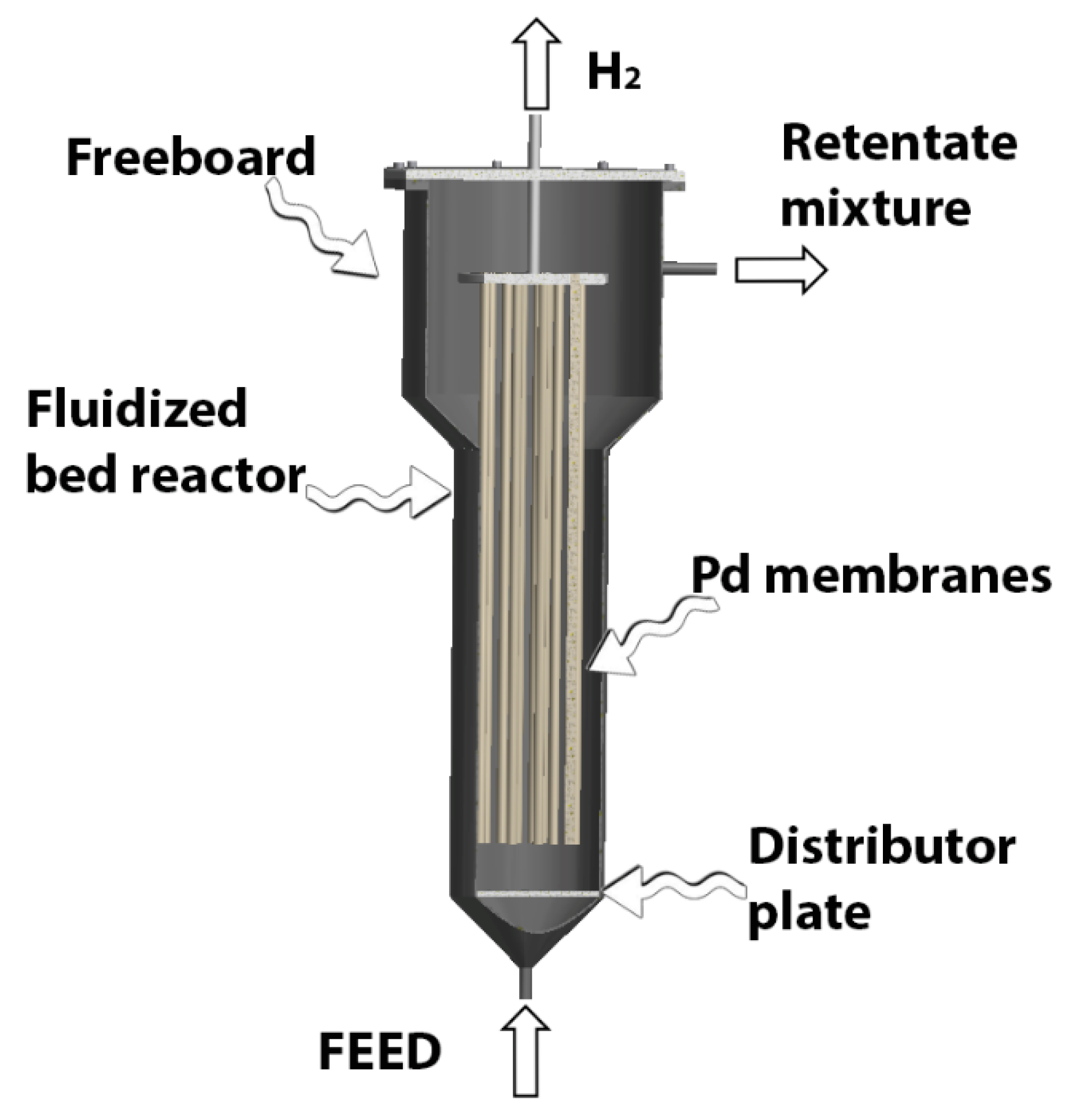
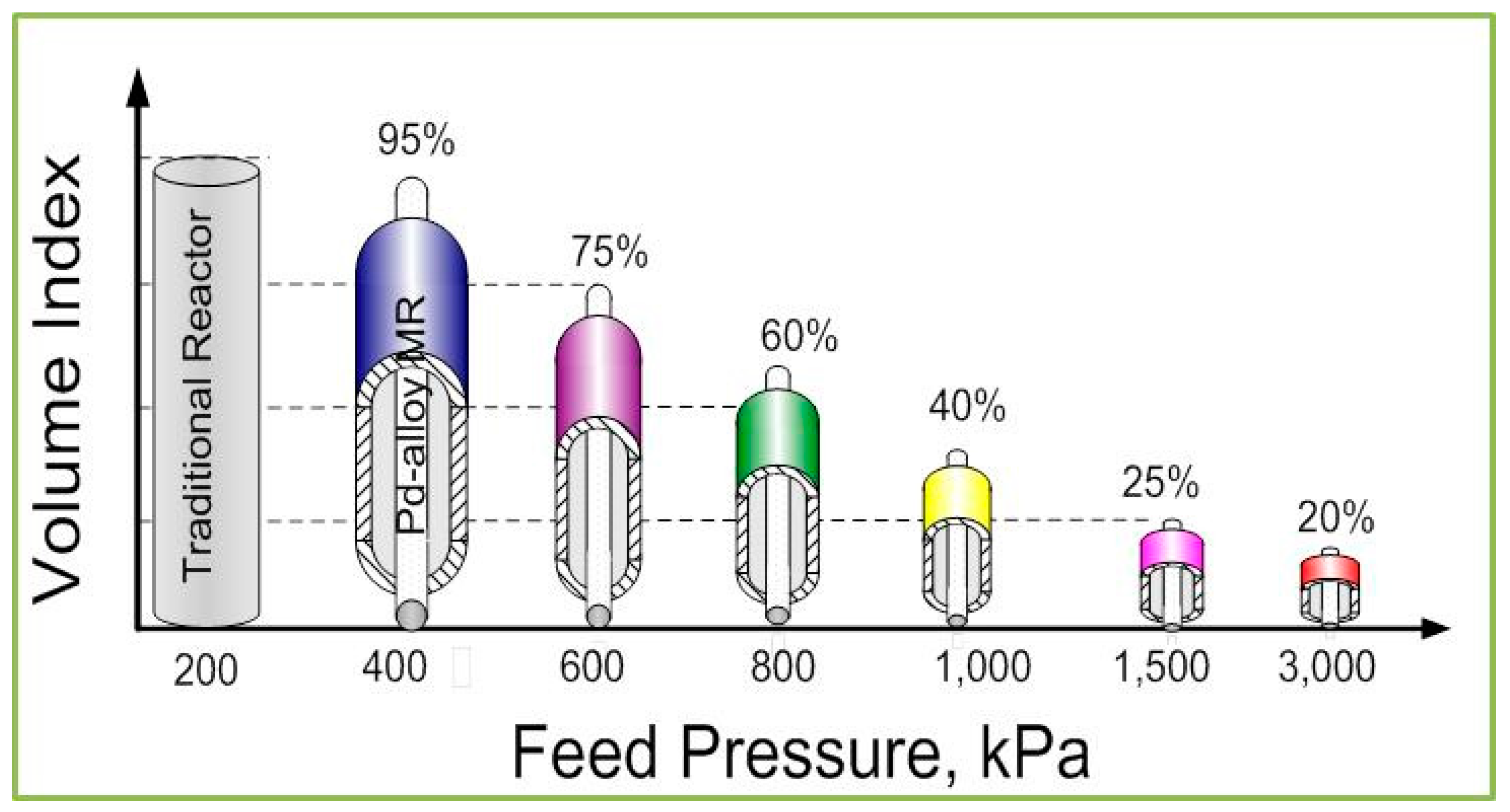
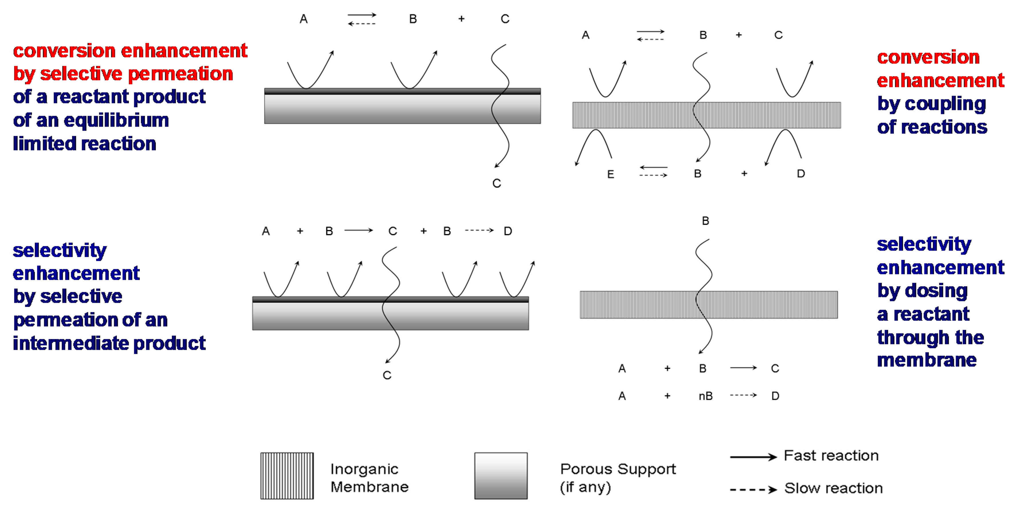
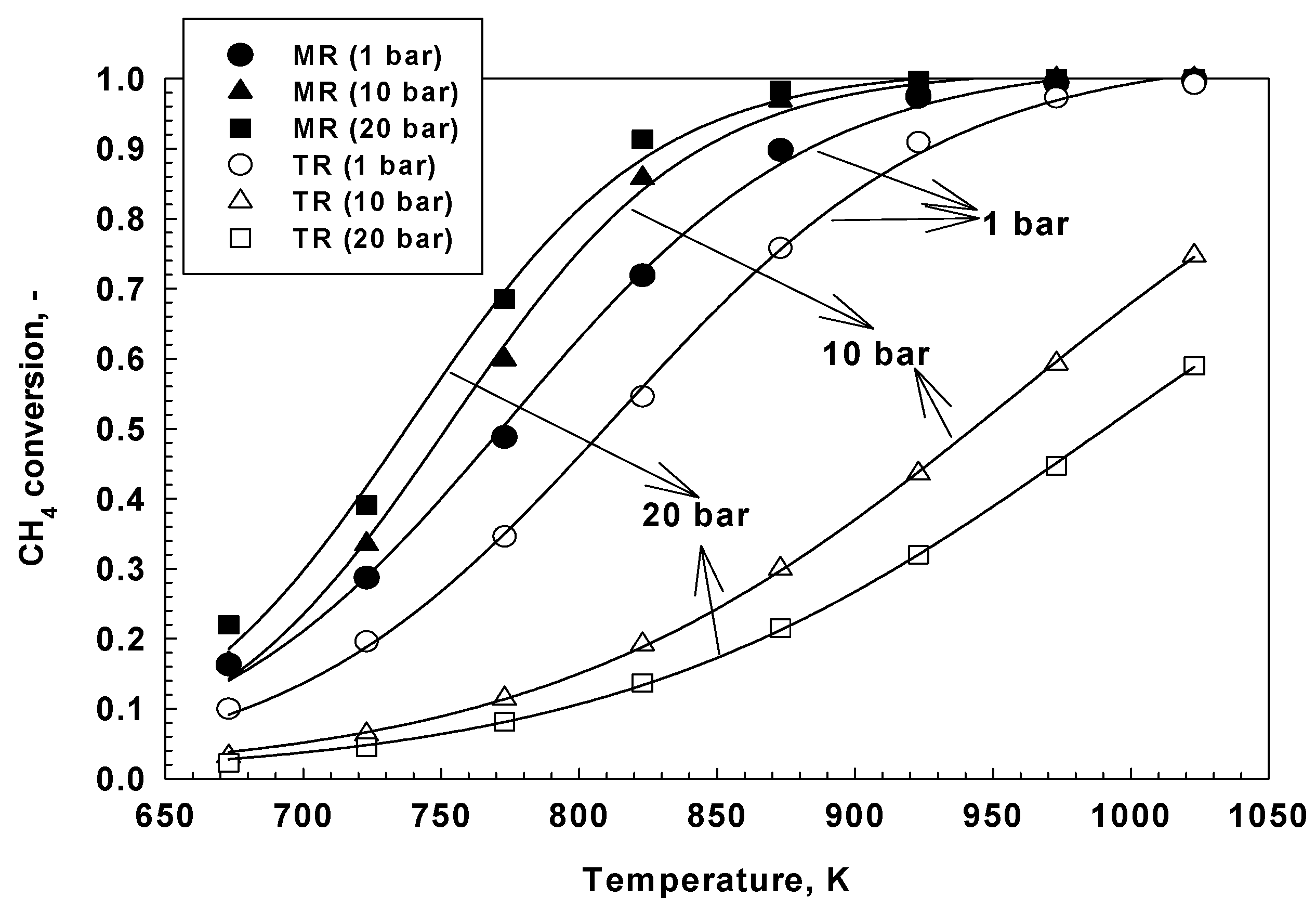
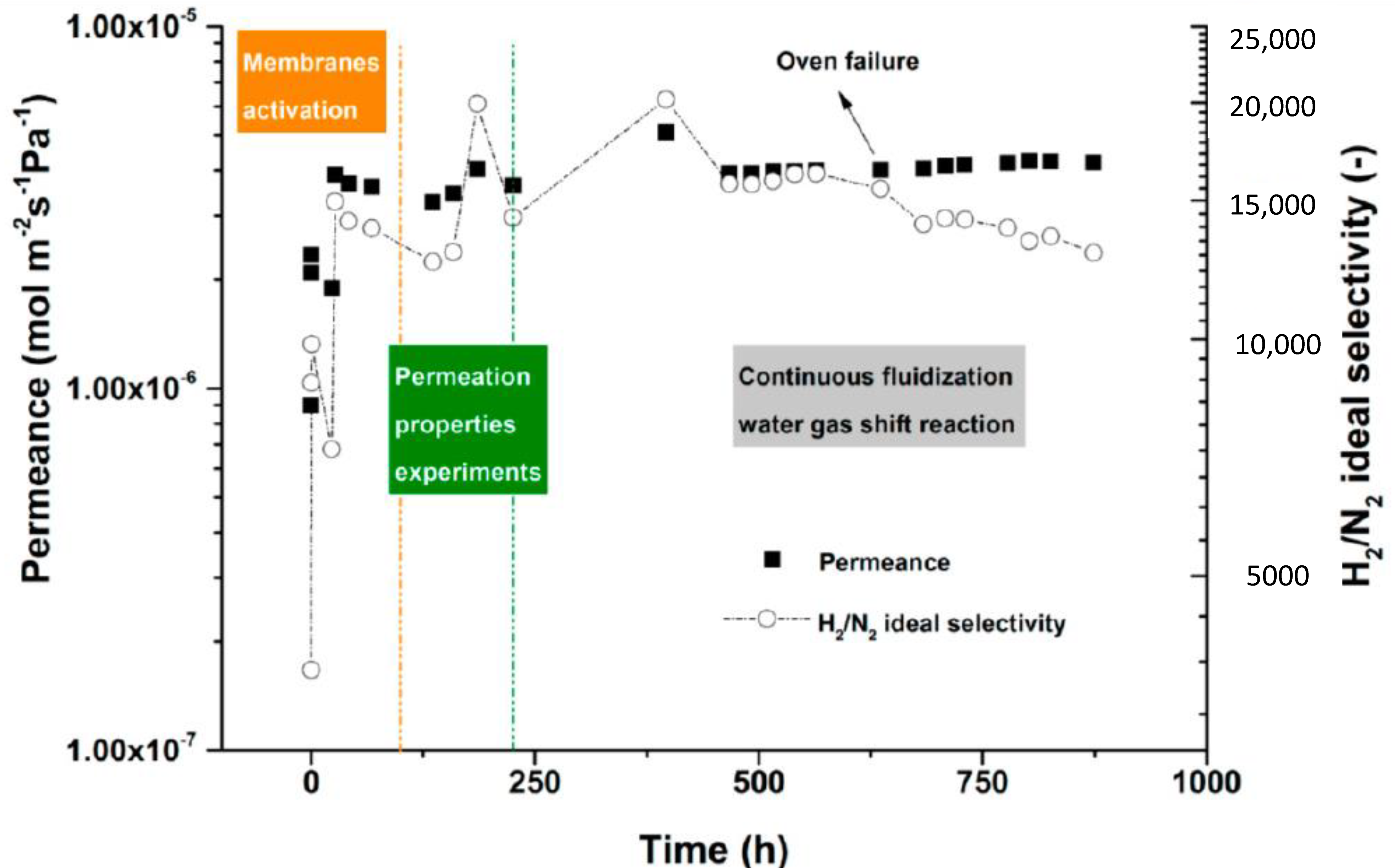
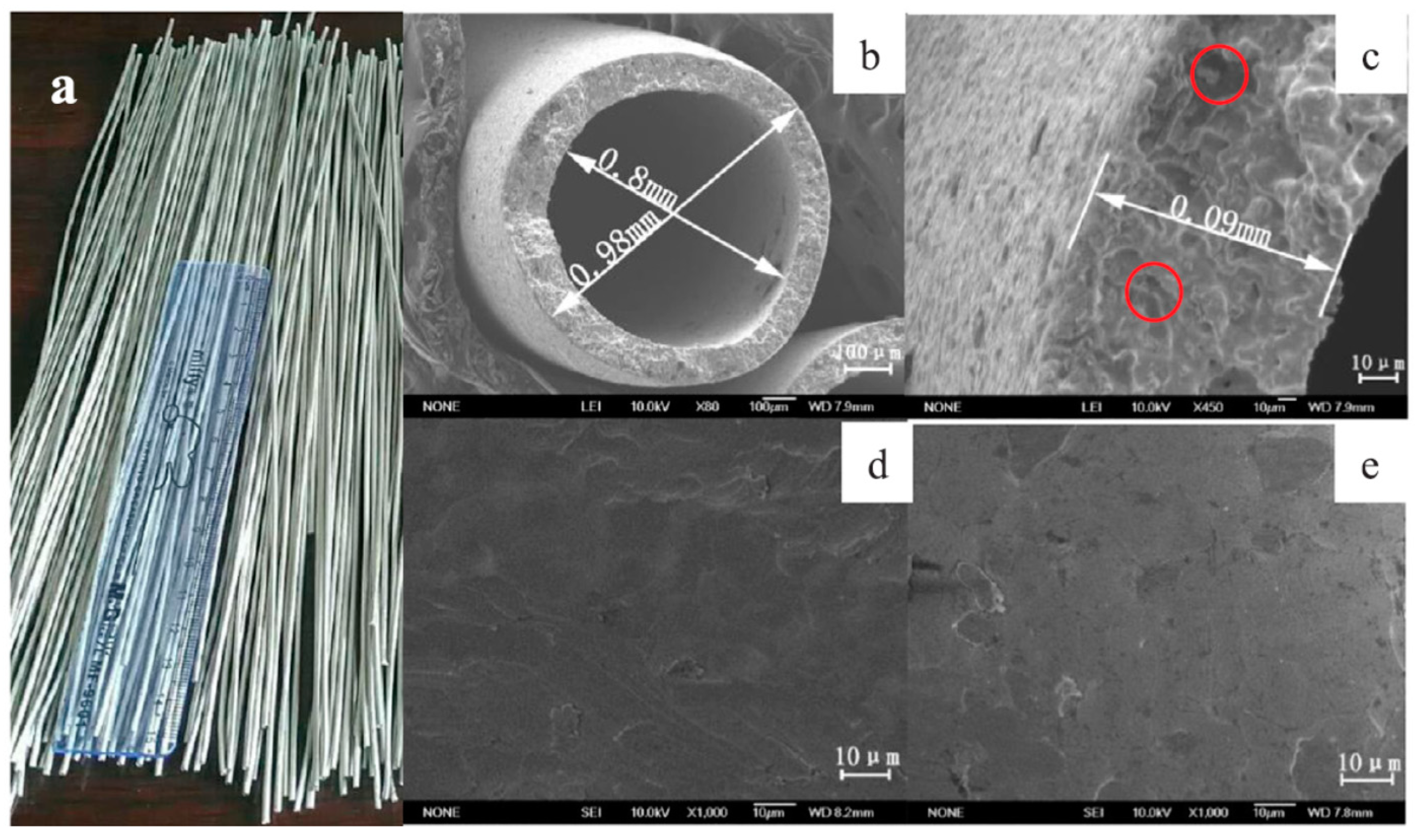
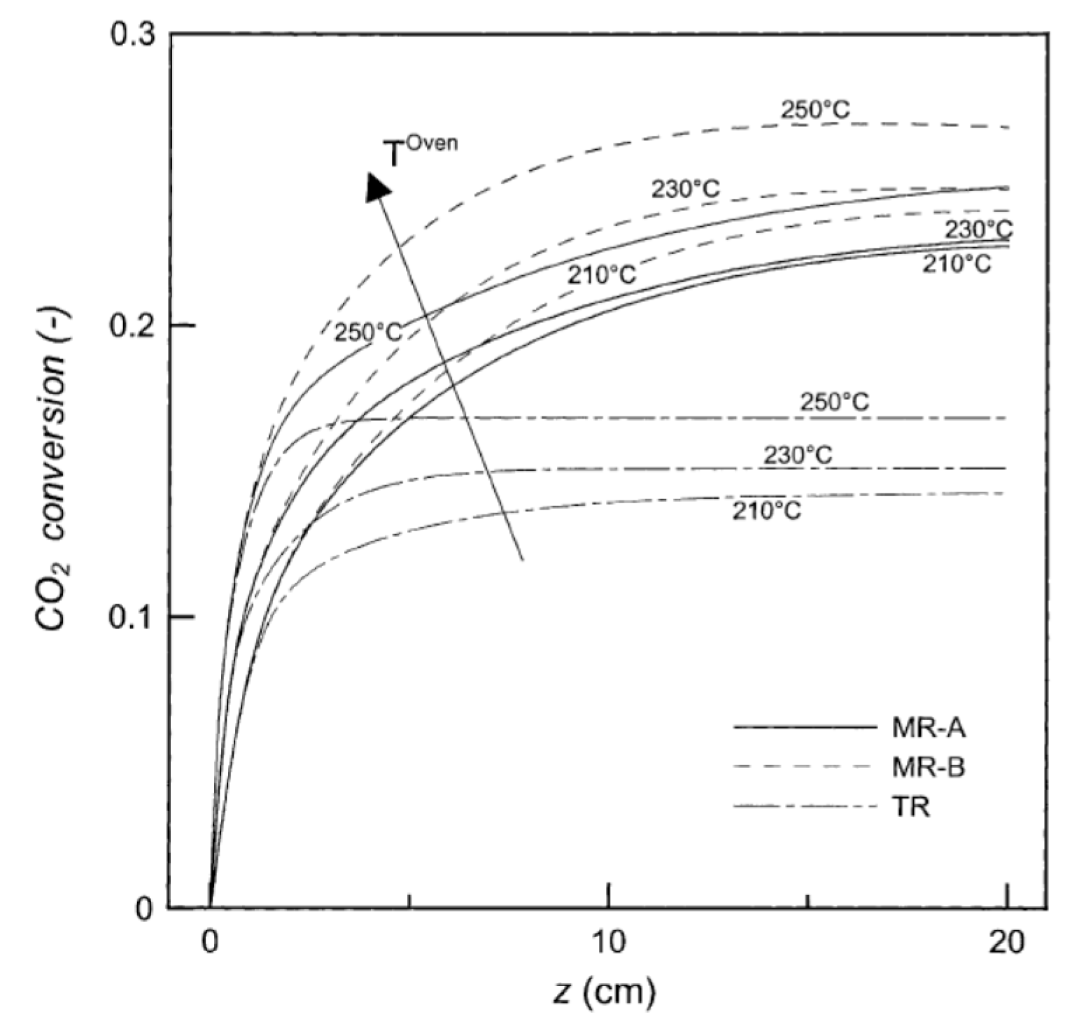
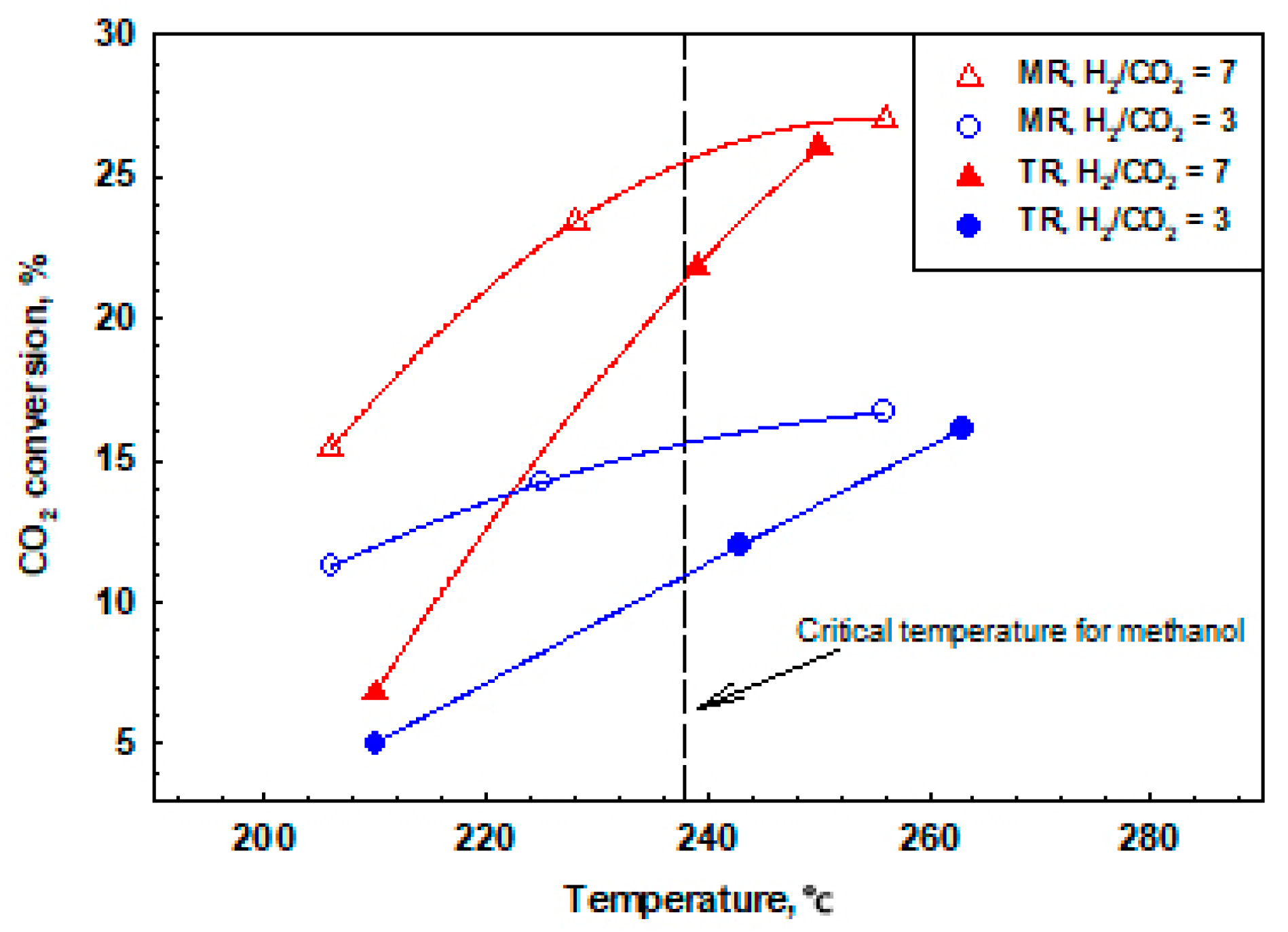
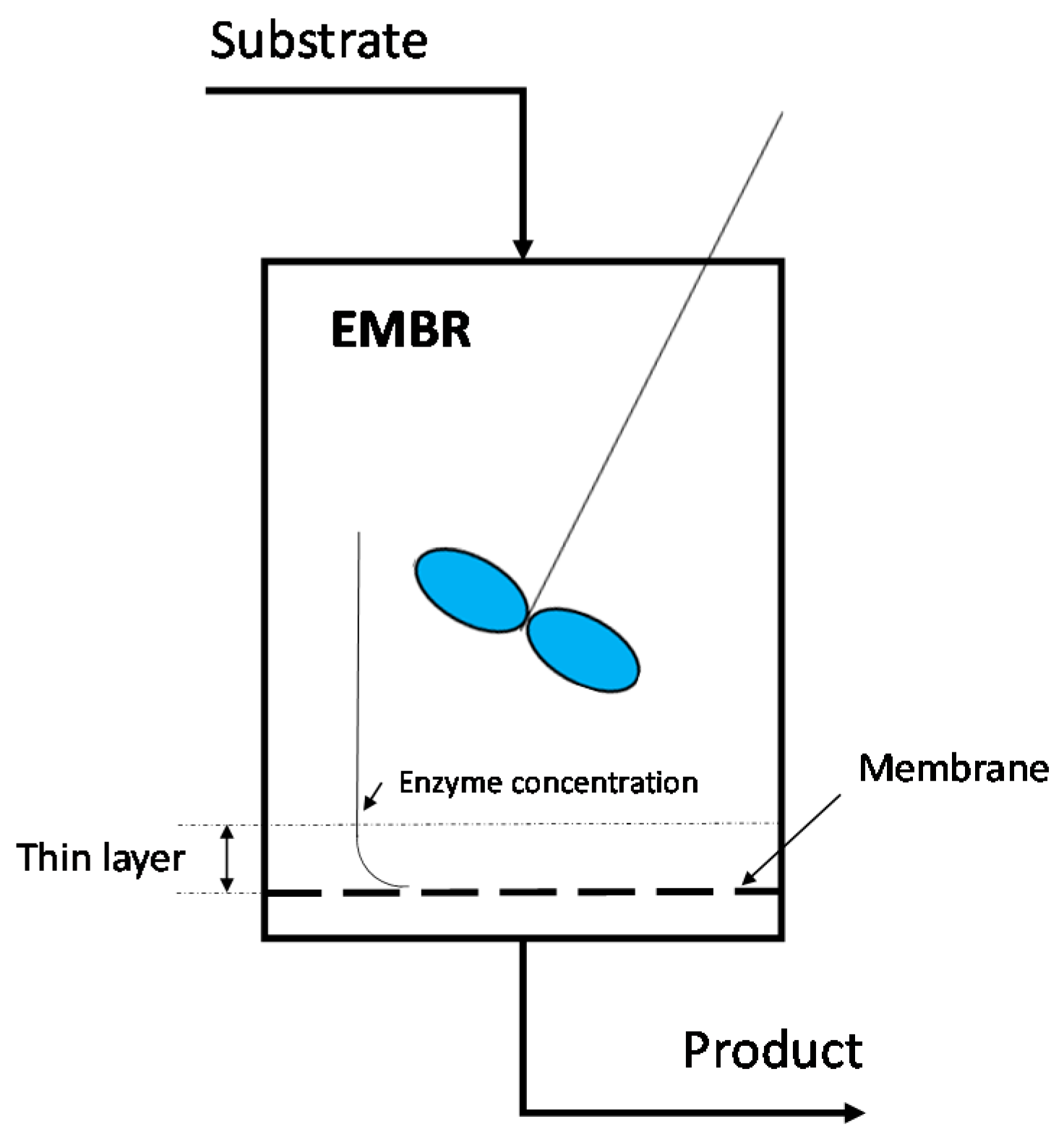
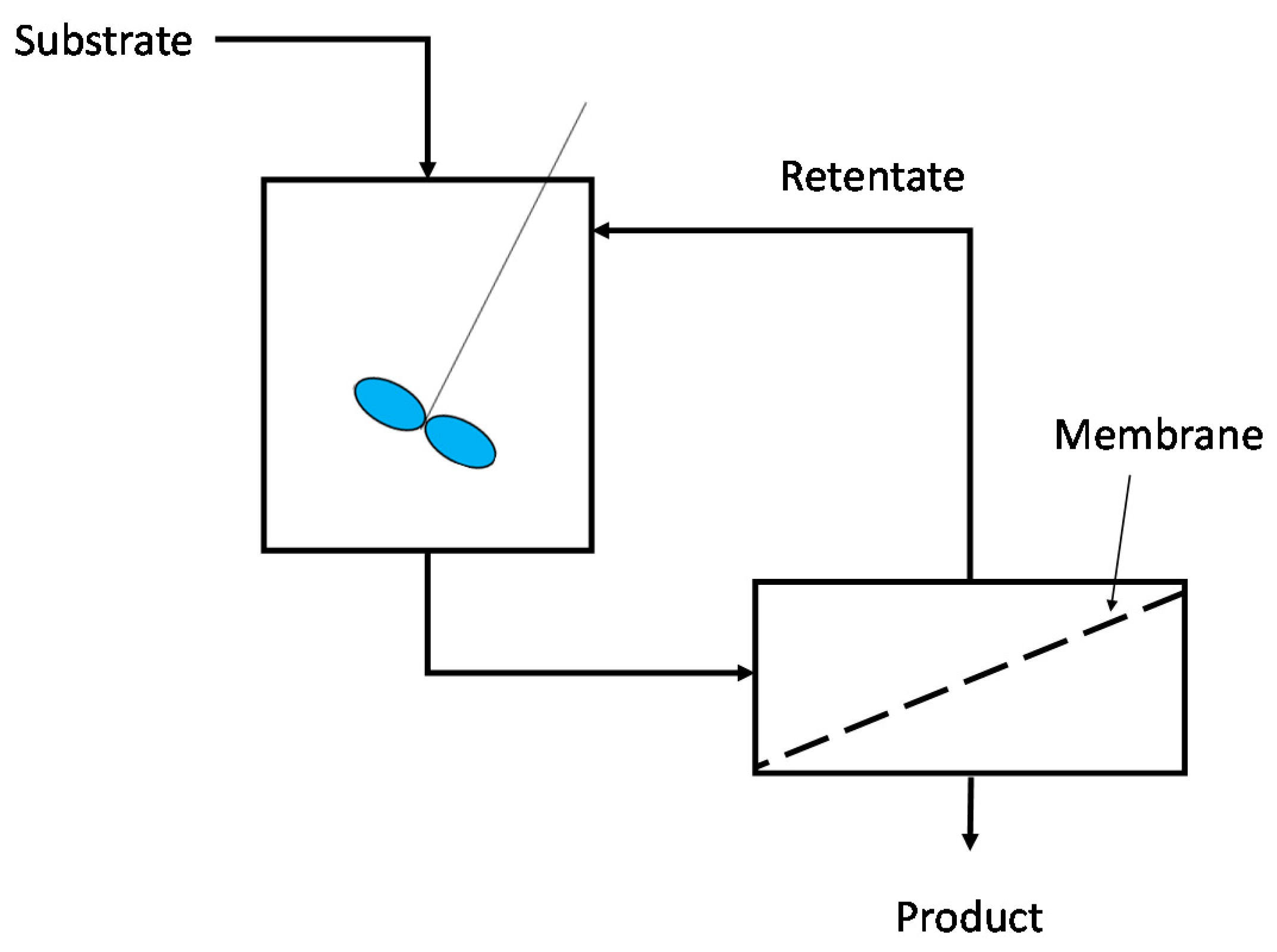
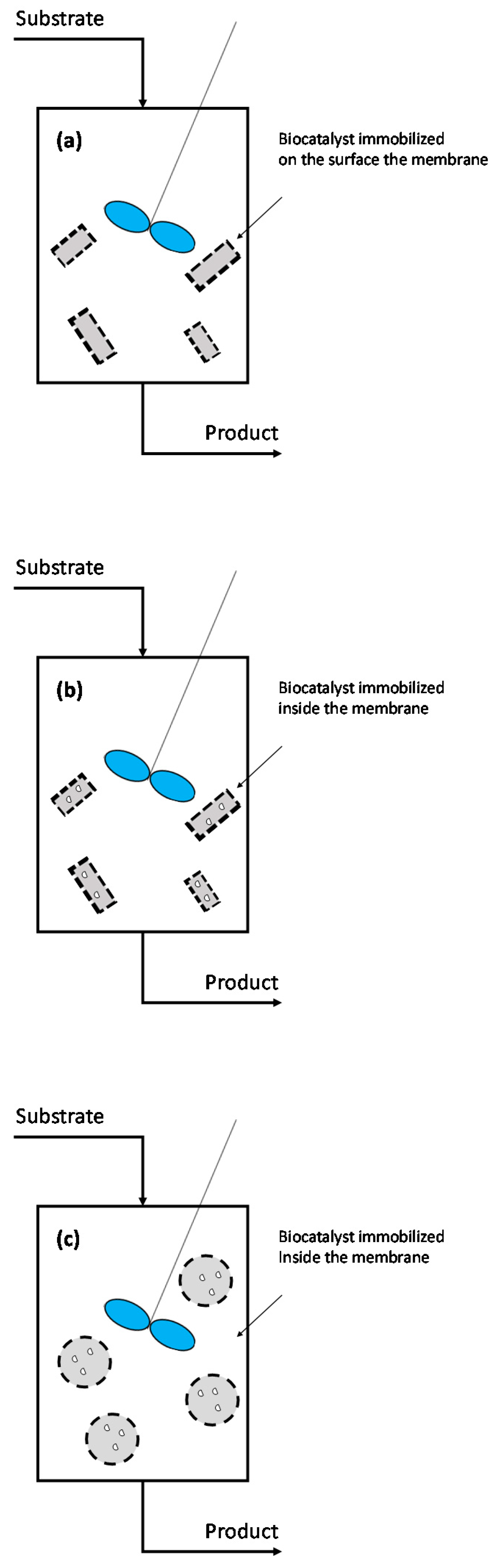
Table 1.
Reactions considered for hydrogen production in membrane reactors.
| Reaction | |
|---|---|
| Water gas shift (WGS) | |
| −41.1 | |
| Methane decomposition (Carbon production) | |
| 75 | |
| Steam reforming (SR) reactions | |
| 206.2 | |
| 164.9 | |
| 49 | |
| 239.5 | |
| 173 | |
| Partial and full oxidation reactions | |
| −802 | |
| −71 | |
| −35.6 | |
| −192.3 | |
| −14.4 | |
| Autothermal reforming (ATR) reactions | |
| 339 | |
| 0 | |
| −50 | |
| Dehydrogenation reaction | |
| 124 | |
| Ammonia decomposition | |
| 45.9 |
Table 2.
Different membrane configurations in an MBR [111].
Table 2.
Different membrane configurations in an MBR [111].
| Configuration | Turbulence Promotion * | Can Be Backflushed? | Membrane Processe(s) | Suitable for MBR? |
|---|---|---|---|---|
| Pleated filter cartridge | Very poor | No | DE-MF, low TSS waters | Yes |
| Flat sheet | Fair | No | ED, UF, RO | Yes |
| Spiral-wound | Poor | No | RO/NF, UF | Yes |
| Multi tubular | Very good | No | CF-MF/UF, high TSS waters, NF | No |
| Capillary tube | Fair | Yes | UF | No |
| Hollow fibre | Very poor—fair | Yes | MF/UF, RO | No |
DE = dead end, CF = crossflow, TSS = total suspended solids. * depends on the packing density and contact between phases (liquid-air).
Table 3.
Most recent large-scale MBR plants worldwide [125].
Table 3.
Most recent large-scale MBR plants worldwide [125].
| Installation | Location | Technology Suppliers | Capacity (PDF) | Commissoning Date |
|---|---|---|---|---|
| Beihu WWTP | Hubei, China | Beijing Origin Water Technology Co., Ltd. (BOW) | 1040 | 2019 |
| Hendriksdal Sweden | nr Stockholm, Sweden | SUEZ—Water Technologies & Solutions | 864 | 2019 (stage 2) |
| Al Ansab | Muscat, Oman | Kubota | 125 | 2018 |
| Water Affairs Integrative EPC | Xingi, Guizhou, China | Beijing Origin Water Technology Co., Ltd. (BOW) | 399 | 2016–2017 |
| Huaifang Water Recycling Project | Beijing China | Memstar | 780 | 2016 |
Table 4.
MBR module suppliers.
| Product | Supplier |
|---|---|
| Immersed flat sheet (FS) modules |
|
| Immersed hollow fiber (HF) modules |
|
| Side stream MBR products (MT) modules |
|
Table 5.
Various MBR manufacturing industries and their products and services.
| Type | Product/Service | Companies |
|---|---|---|
| System integrators | Membranes, membrane modules, pumps, tanks, etc. |
|
| Component manufacturers | Membranes. |
|
| Membrane bioreactor systems | MBR system is built and membranes and membrane modules are provided by the membrane manufacturer. |
|
| Application-specific MBR and AnMBR | These companies focus on a specific area. |
|
© 2020 by the authors. Licensee MDPI, Basel, Switzerland. This article is an open access article distributed under the terms and conditions of the Creative Commons Attribution (CC BY) license (http://creativecommons.org/licenses/by/4.0/).
Share and Cite
MDPI and ACS Style
Helmi, A.; Gallucci, F. Latest Developments in Membrane (Bio)Reactors. Processes 2020, 8, 1239. https://doi.org/10.3390/pr8101239
AMA Style
Helmi A, Gallucci F. Latest Developments in Membrane (Bio)Reactors. Processes. 2020; 8(10):1239. https://doi.org/10.3390/pr8101239
Chicago/Turabian StyleHelmi, Arash, and Fausto Gallucci. 2020. "Latest Developments in Membrane (Bio)Reactors" Processes 8, no. 10: 1239. https://doi.org/10.3390/pr8101239
Note that from the first issue of 2016, this journal uses article numbers instead of page numbers. See further details here.