Article

Investigation on Vortex Characteristics of a Multi-Blade Centrifugal Fan near Volute Outlet Region

1
Faculty of Aeronautical Engineering, Taizhou University, Taizhou 318000, China
2
National-Provincial Joint Engineering Laboratory for Fluid Transmission System Technology, Zhejiang Sci-Tech University, Hangzhou 310018, China
3
Zhejiang Yilida Ventilator Co., Ltd., Taizhou 318056, China
*
Author to whom correspondence should be addressed.
Processes 2020, 8(10), 1240; https://doi.org/10.3390/pr8101240
Submission received: 29 July 2020 / Revised: 21 September 2020 / Accepted: 27 September 2020 / Published: 2 October 2020
(This article belongs to the Special Issue CFD Applications in Energy Engineering Research and Simulation)

Abstract

:
The origins and effects of the complex vortex structure near the volute outlet of a multi-blade centrifugal fan are investigated in this paper. Due to the wide blade and short blade channel, the airflow maintains a large radial velocity during the blade channel. This continuous radial partial velocity causes vortices to be generated at the region of volute outlet. Then, the secondary flow close to the impeller generate from the center to the sides in volute. It is obtained that the streamlines are divided into two parts (backflow and outflow) at volute outlet. Although the vortices near volute outlet region are complex, the main features of flow behavior caused by the vortex are understandable.

1. Introduction

The multi-blade centrifugal fans are widely used in heating, ventilation, air conditioning, and other fields. Kinds of centrifugal fan with small size coefficient and low noise mainly possess a great deal of outstanding advantages [1,2]. It is of great significance to improve the performance of centrifugal fan. Ballesteros et al. [3] investigated the unsteady flow conditions of the flow field of the multi-blade fan inlet flow, the intra-blade flow, and the outlet flow channel, and summarized their respective characteristics under different working conditions, respectively. Velarde et al. [4] pointed out the strong non-uniformity of the flow state in the blade channel of the multi-blade fan. The blade channel has obvious flow separation points and separation areas, the strong pressure pulsation at the volute, and the pressure distribution in the volute are asymmetric.
Adachi et al. [5,6,7,8,9] studied the influences of blades on the flow field and the performance of multi-blade centrifugal fans. Wang [10] studied the influence of blade trimming on the performance of multi-blade centrifugal fan. They argued that the blade trimming with proper trimming parameter enables the multi-blade fan to get an increasing fan performance. Kind et al. [11] proposed a method to predict the aerodynamic performance and flow state of the forward multi-blade centrifugal fan. This method decomposes the whole fan into three parts, namely the inlet part, the blade part, and the volute part. The main target should be placed on the blade and the gap. However, the vortices at the outlet extension of the multi-blade centrifugal fan also possess a significant influence on the aerodynamic performance of fan, so the optimization of the outlet extension should also be paid attention to. Velarde et al. [12] measured the velocity fluctuation at the outlet of a forward multi-blade fan by using the hot wire method and found that the outlet of the fan presented a strong asymmetry, especially at the volute tongue. Wen et al. [13] proposed two volute design methods to overcome the space limitation of the volute. The effects of turbulent flow structure on the performance of a centrifugal fan were studied numerically and experimentally [14,15]. The numerical studies [16,17,18,19,20] demonstrated that numerical simulations play an increasingly important role in fan performance design. Wang et al. [21] proposed that the representation technique is capable of effectively getting the nonuniform circumferential flow conditions at both the outlet and inlet of fan impeller.
The above researches show that the region between the impeller and volute plays an important role in the fan performance. Complex vortices are also mainly caused by the Coriolis force and unsteady separated flow. Interestingly, several complex vortex structures are easily formed and captured near the junction of the volute outlet and the outlet channel extension section, which blocks the pneumatic conveying of centrifugal fan. This phenomenon greatly suppresses the aerodynamic performance of multi-blade fan. There are great differences between the actual flow field features and the theoretical derivation, especially the influence of the vortex structure at the outlet of the volute on the performance of the fan. The volute plays a key role in effective work of the centrifugal fan and directly affects the performance of fan. Complex vortex structure near volute outlet is caused by Coriolis force and the unsteady flow in narrow blade channel. The aim of this paper is to provide some fundamental understanding of the complex vortex structure on the volute outlet by numerical simulations and to provide some physical insight into the control of unsteady flow field, rather than the performance of fan and results for specific applications.

2. Experimental Test of Aerodynamic Performance for Multi-Blade Fan

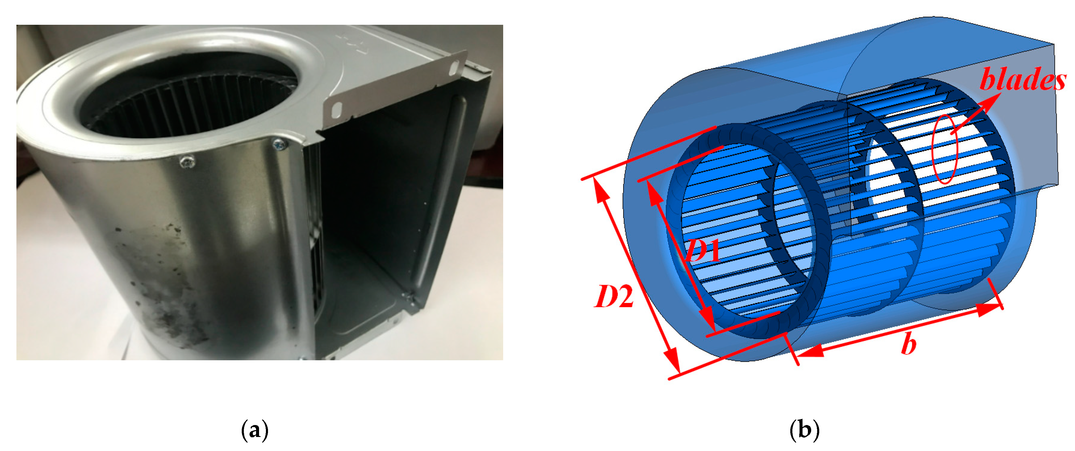
2.1. Key Parameters of Multi-Blade Fan Model

The several important parameters of multi-blade fan are shown in Figure 1 and Table 1. Figure 1 shows the physical picture of the centrifugal fan, which includes a volute and an impeller. As illustrated in Table 1, it is seen that the number of the impeller blade is 40, the impeller width (b) is 200 mm, the impeller diameter (D2) is 150 mm, the angle of blade inlet (β1) is 90°, the outlet angle of blade (β2) is 27°, respectively.

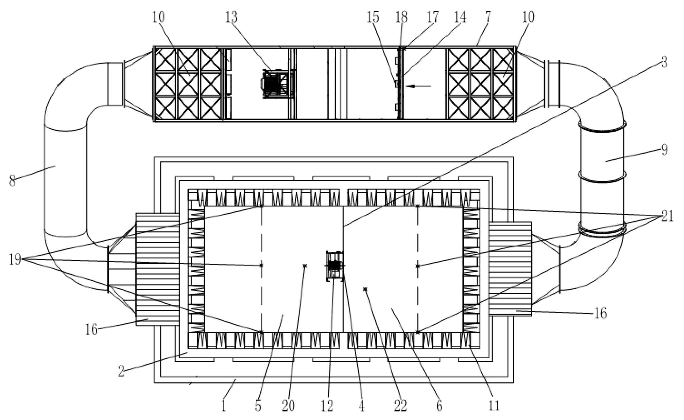
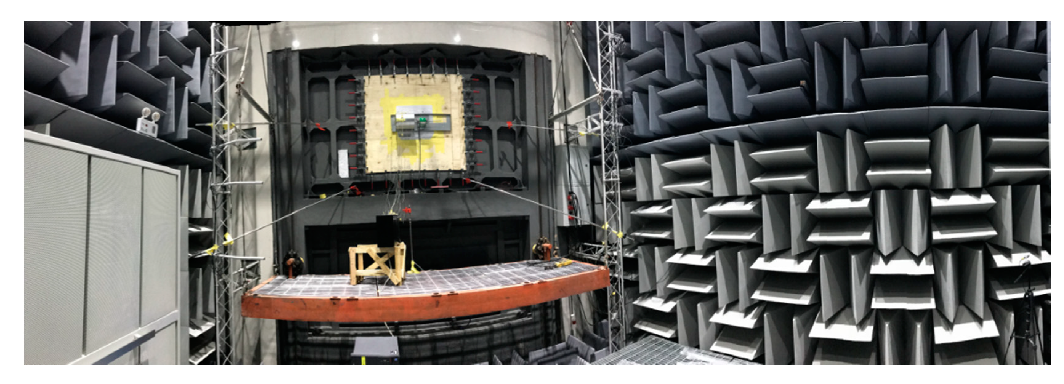
2.2. Laboratory Testing

The aerodynamics performance of the multi-blade fan was tested in the Zhejiang Yilida aerodynamics laboratory. The aerodynamics performance of a smulti-blade fan is usually obtained by total pressure Pt (Pa)-the flow rate of volume Q (m3/h). The total pressure is the sum of dynamic pressure and static pressure. The total pressure of multi-blade fan is the difference between total pressure at the inlet and outlet of fan, its expression is followed as:
P t = P s t + P d
η = P t × Q 1000 N
where Pst denotes the static pressure, Pd denotes the dynamic pressure, η is the efficiency of total pressure and N is the power. The aerodynamic performance test consists of negative pressure chamber, the positive pressure chamber and gas tunnel. Figure 2 illustrates the experimental system, and Figure 3 describes the photograph of the negative pressure chamber in the laboratory schematic. Each air chamber has four pressure taps which are located on the two side walls, the top surface and the ground in the chamber. The results of performance test include the total pressure Pt, the total pressure efficiency η. In this paper, the rated flow of multi-blade fan is 504 m3/h (Q = 504 m3/h), the flow coefficient is φ = 0.79, and n = 1000 r/min.
ψ = P t 1 2 ρ u 2 2
ϕ = Q π 4 D 2 2 u 2
where Ψ is the total pressure coefficient and φ is the flow coefficient, respectively.
As shown in Figure 2, the flow rate was measured by the difference static pressure between the pressure taps before and after the nozzle the nozzle. All the pressure were measured by FCO332 (pressure transmitter, East Sussex, UK). By measuring the power of multi-blade fan, the total pressure efficiency of the multi-blade fan was obtained.

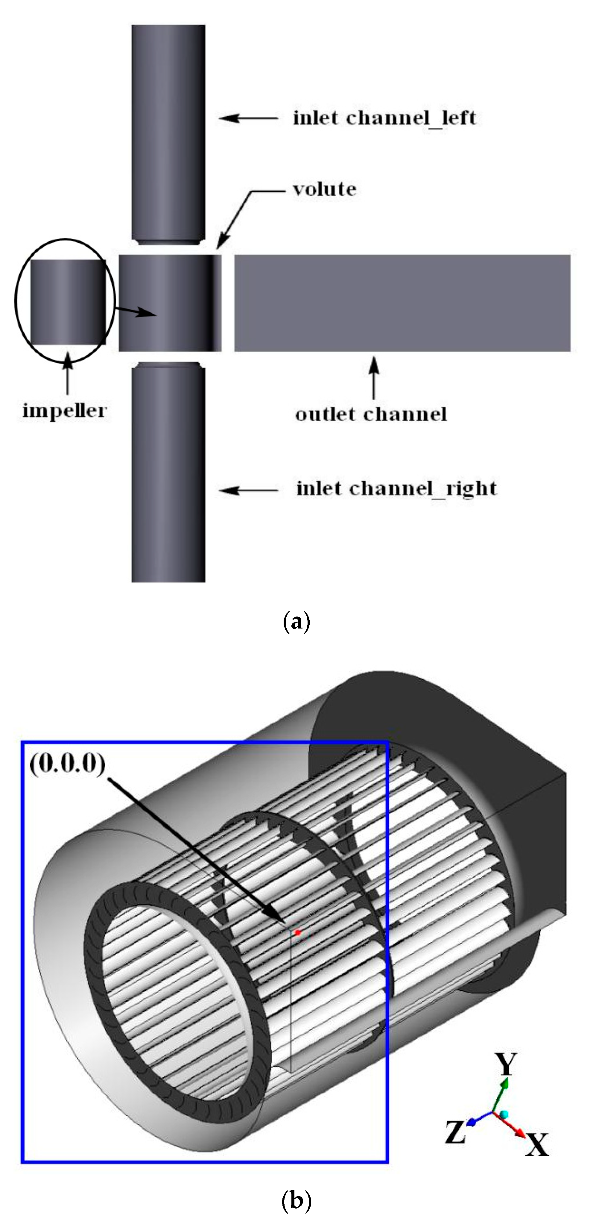
3. Governing Equations and Numerical Method

3.1. Dynamic Model of Incompressible Fluid

The computational fluid dynamics methods are based on the basic governing equations of fluid mechanics: continuous equation, momentum equation, and energy equation. The turbulence models of incompressible Reynolds-averaged Navier-Stokes (RANS) are solved by the finite volume method. The mass and kinetic equations for the internal flow in the multi-blade fan are followed as [22,23]:
ρ t + x i ( ρ u i ) = 0
ρ u i t + x j ( ρ u i u j ) = P x i + x j [ μ e ( u i x j + u j x i ) ] + S i
where ρ denotes the density of fluid, xi and xj are the components x, y, and z in the coordinate system of Cartesian in corresponding directions, P* is the translation pressure, S is the sum of the volume force source terms, and μ is the dynamic viscosity coefficient. The formula of turbulence model Re-normalization group (RNG) k-ε is given as [22]
( ρ k ) t + x i ( ρ u i k ) = x i [ ( μ + μ t σ k ) k x i ] + P k ρ ε + P k b
( ρ ε ) t + x i ( ρ u i ε ) = x i [ ( μ + μ t σ ε ) ε x i ] + ε k ( C ε 1 P k C ε 2 ρ ε + C ε 1 P ε b )
where Cε1 = 1.44, Cε2 = 1.92, σk = 1.0, σε = 1.3, Pεk, Pεb represent the energy terms generated by the buoyancy, and Pk is used to generate the turbulent kinetic energy caused by viscous forces. The pressure boundary condition is used for the inlet of multi-blade fan and the mass flow boundary condition is implemented for the outlet of multi-blade fan. The upwind discretization is implemented in convection terms and the schemes of central difference are implemented in terms of diffusion [23].

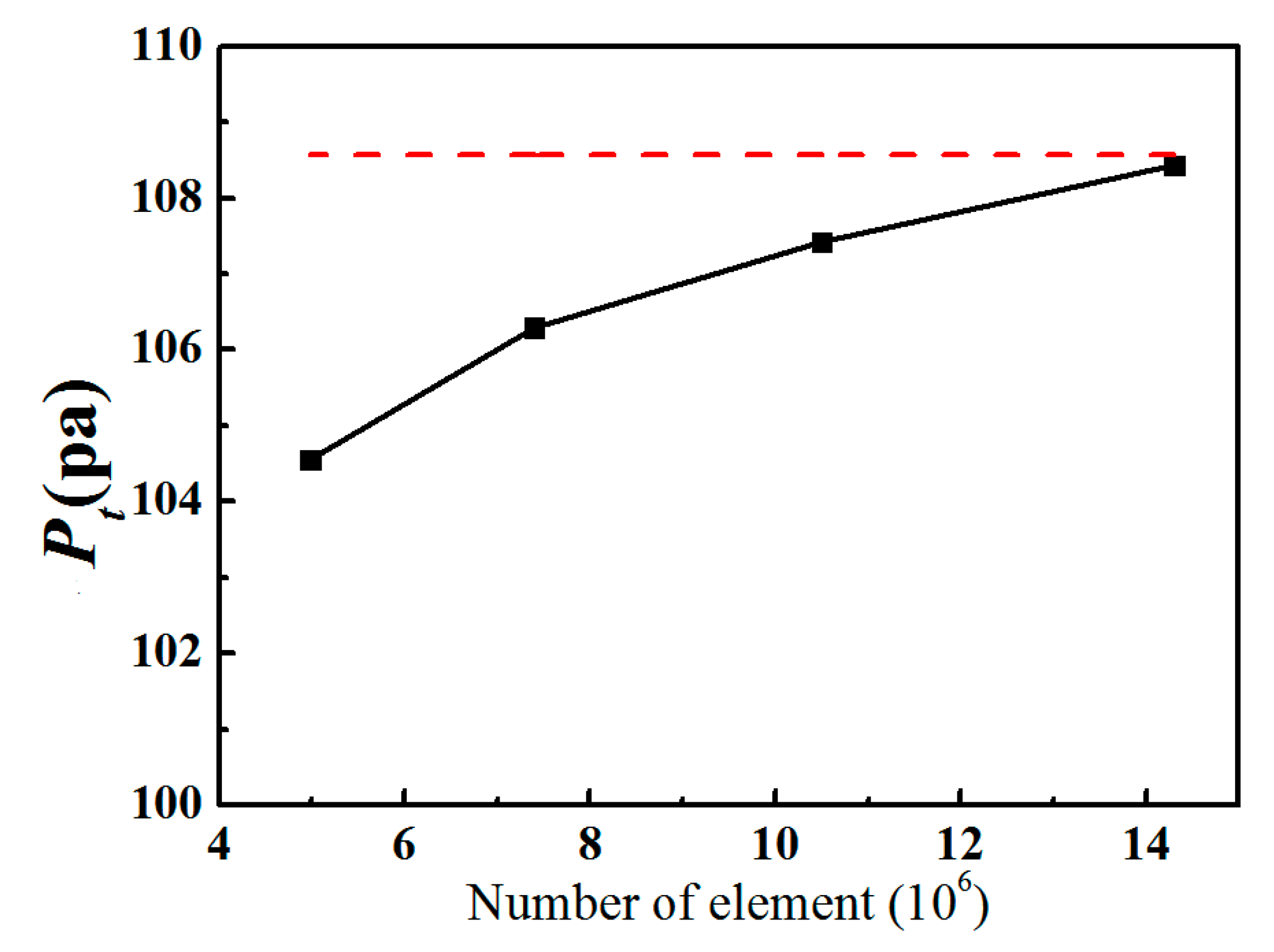
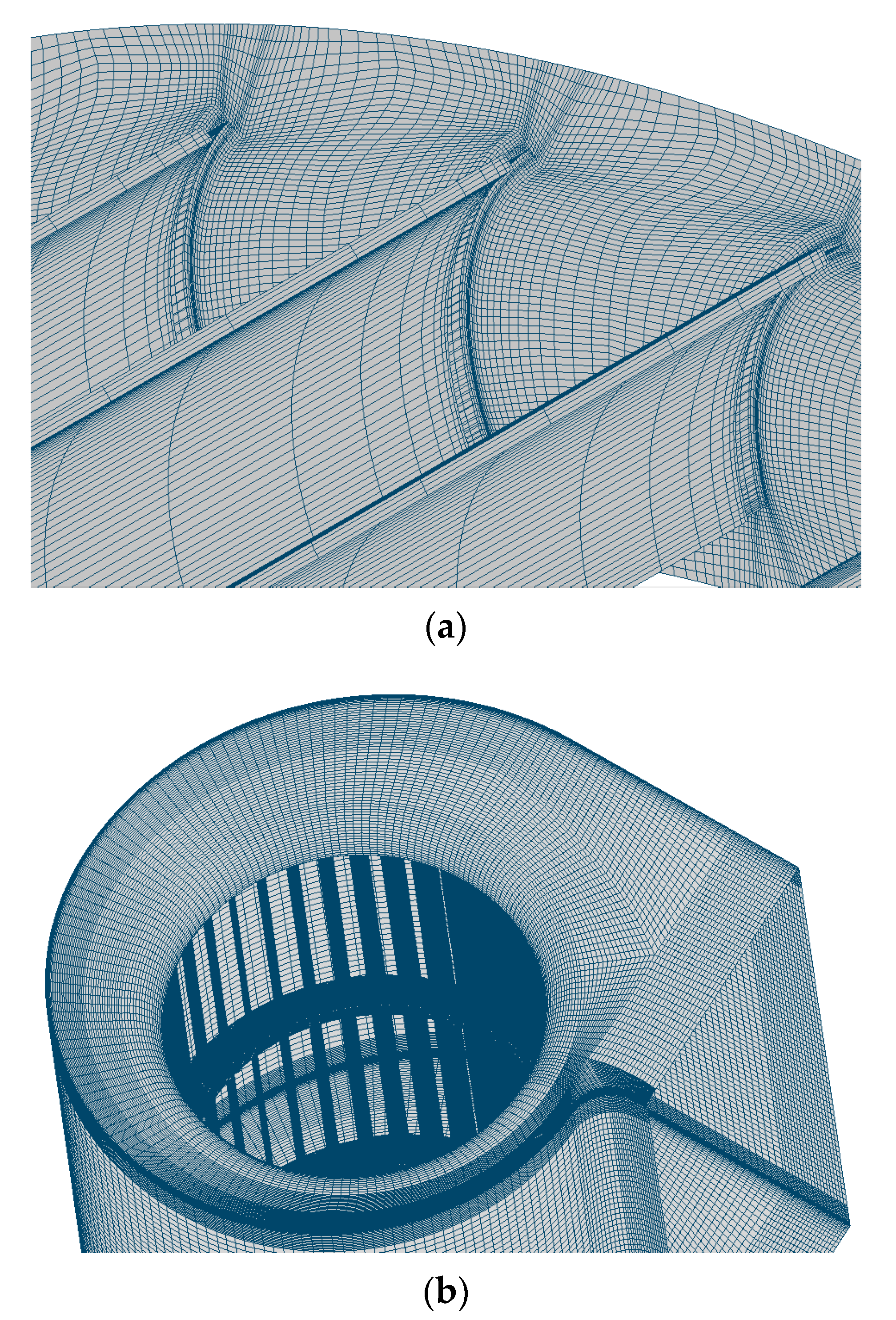
3.2. Grid Independence Verification

The grid independence verification is relatively essential to obtain the high accuracy of numerical simulation and determining the amount of the calculation grid of the whole calculation area. Figure 4 shows the computational domain. Figure 4a illustrates two inlet domains, one volute domain, one outlet domain, and a rotating impeller domain. Figure 4b illustrates coordinate and origin of the impeller rotation. The size of every domain in Figure 4a should be presented here. The inlet boundary condition is the static pressure boundary condition and the outlet is the flow rate boundary condition. Different flow coefficients are obtained by varying the flow rate of outlet. A pair of dynamic and static interfaces are used for data transfer between the rotating part (impeller) and non-rotating part (volute). The Multiple Reference Frame (MRF) is used to set the rotating part (impeller). The rotating speed and torque of impeller are implemented to obtain the simulation power of the multi-blade fan.
To verify the grid independence of numerical simulations, four models with different grid resolutions, including 4.98 × 10⁶, 7.40 × 10⁶, 1.05 × 10⁷, and 1.43 × 10⁷, are implemented at flow rate condition (Q = 321 m3/h). Figure 5 describes the relation between the total pressure and grid numbers. It is clearly seen that the total pressure of numerical simulation approaches the experimental results with the increment of the grids number. When the grid number reaches 1.05 × 10⁷, the relative difference of total pressure between the numerical simulation results and the experimental results is only 1%, which proves that the grid resolution is fine enough for numerical results. Finally, to consider the accuracy and cost, a grid division method (topology method and grid node number setting) with a total grid of 1.05 × 10⁷ (the computational time is about 11.5 h with 20 processes) is implemented instead of the 1.43 × 10⁷ one (the computational time is about 24 h with 20 processes) in all numerical simulations.
Figure 6 shows the topological block structure and mesh region of the fan. The mesh density is increased towards the walls. As the inside flow of impeller is the very complicated, the mesh of impeller blade is refined in Figure 6a. The grid of volute region is refined in Figure 6b.

4. Numerical Results and Some Discussions

In the following section, the complex internal flow fields of multi-blade fan will be presented and discussed. The vortex structure between outlet channel and volute will be studied. The origins and impacts of the complex flow structure on the volute outlet are further investigated.

4.1. Verification of Numerical Results

In order to prove the accuracy of numerical simulations, the reference model is used to study the total pressure and the efficiency of total pressure at various rate of flow. Figure 7 describes the comparison of numerical and experimental results about the total pressure and the efficiency of total pressure. The red solid line denotes the experimental results and the black line represents the numerical results, respectively. As described in Figure 7, it can be observed that the pressure coefficient gradually decreases with increasing flow coefficient, the pressure coefficients of numerical simulations are excellent consistent with that of experiment, and the total pressure efficiency of numerical simulations well agree with the experimental results in a range of medium and large flow rates. The numerical efficiency does not match the experimental results well at the low mass flow conditions. This mainly due to the error of motor efficiency at low power condition. As illustrated in Figure 7, one clearly observes that the total pressures of numerical simulations are in good agreement with the experimental results, which demonstrates that the method of numerical simulation is reliable in this paper [24,25].
The origins and impacts of the complex flow structure on the volute outlet are investigated. In order to demonstrate the detail of vortex near volute outlet, the streamline diagram with different flow coefficient will be presented and discussed in the following subsection.

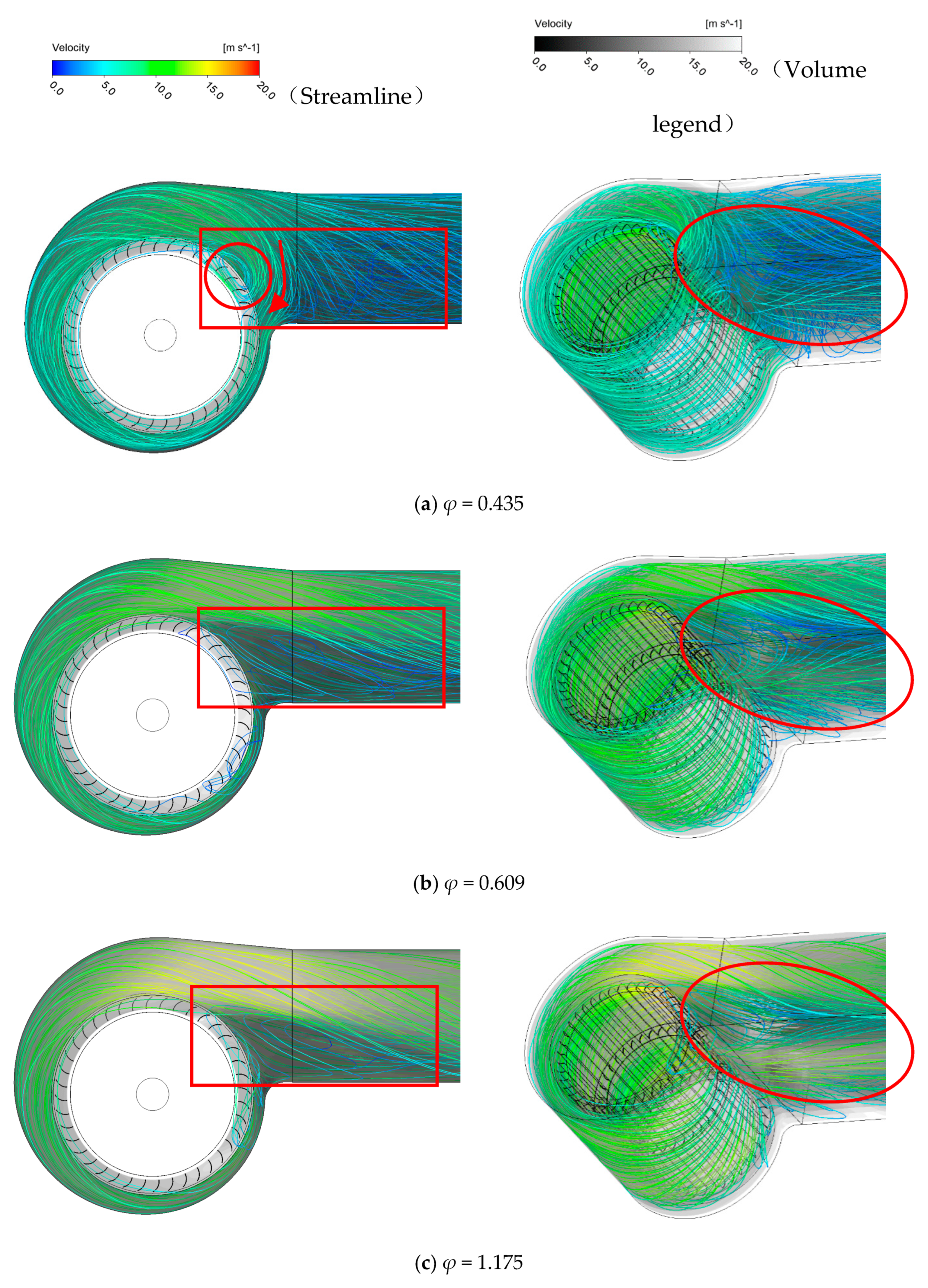
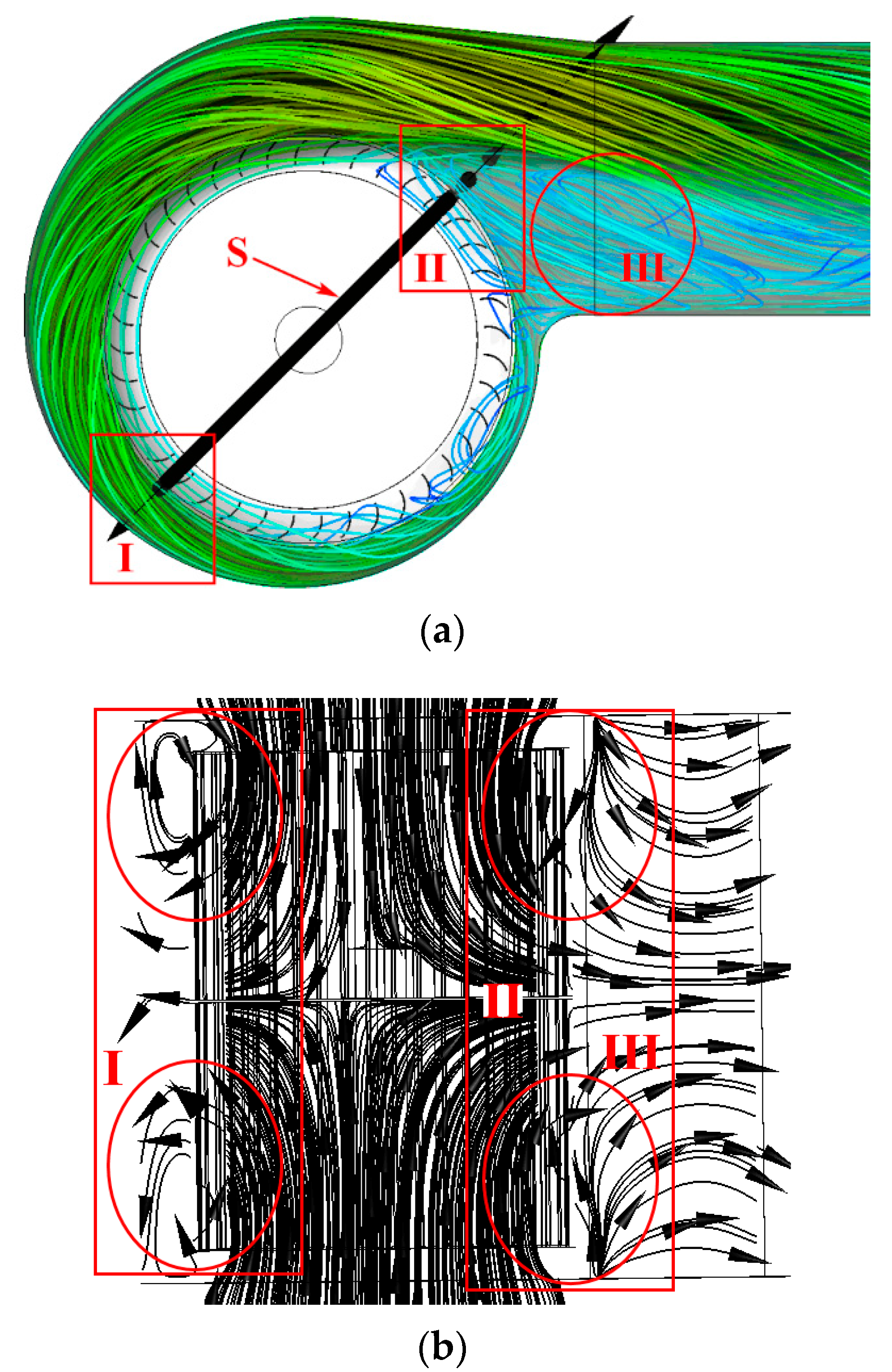
4.2. Effect of Volute Outlet Vortex on Flow

Figure 8 shows the three-dimensional streamline distribution in the volute and the outlet of the volute. As illustrated in Figure 8a, it is obviously observed that the streamline is equally divided into two parts (backflow and outflow), where φ = 0.435 is a small flow condition, φ = 0.609 is a high efficiency condition, and φ = 1.175 is a high-flow condition, respectively. As shown in Figure 8a, it is clearly obtained that the flow field near the volute side wall of the multi-blade fan near the volute exit is relatively chaotic, and an obvious vortex can be observed at small flow conditions. A large area at the exit of the volute has a backflow phenomenon. From Figure 8a, it can be observed that most of the airflow from the impeller exit does not leave the fan by the volute exit but flows back to the volute through the volute. At this time, the airflow exits the volute and leaves the fan mainly through a limited passage near the upper wall of the volute. As shown in Figure 8b, one can see that a vortex appears in the junction between the volute exit and the fan outlet extension at high-efficiency conditions. The vortex goes down to the volute and up to the volute. At the half-height position of the exit, it is close to the volute side in the axial direction. Plotted in Figure 8c, at high flow conditions, the vortex area at the exit of the volute is slightly smaller than that at higher efficiency conditions. With increasing flow rate of fan, the volute exit flow rate is bound to increase, and the increasingly volute exit air velocity compresses the volute exit vortex area. As shown in Figure 8b, one volute exit vortex can be observed at the left and right side walls of the volute, and the two vortex structures are similar analysis. At the flow point of high efficiency working condition of fan, a large area of vortex structure appears in the exit of the volute. The analysis and study of this vortex structure are very helpful to understand the flow optimization of the multi-blade fan.
In order to investigate the flow characteristics of the vortex at the outlet of the volute, the velocity distribution of the impeller outlet is studied. Figure 9 illustrates the Line B-Outlet of the impeller. Plotted in Figure 9, the ‘B-Outlet-Z25’ means “the line near blade trailing at the cross-section Z = 25 mm” (where Z = 0 mm is located at the impeller center). The distribution position of 0° to 360° is illustrated in Figure 9.
From Figure 10, Figure 11, Figure 12, Figure 13, Figure 14, Figure 15, Figure 16 and Figure 17, all the simulation results are obtained at the high efficiency condition and the flow coefficient (φ) is 0.609. Figure 10 illustrates the absolute velocity distribution of the line ‘B-Outlet-Z’. As illustrated in Figure 10, one can see that the fluctuation of velocity due to multiple blades is very obvious at the area of 90° to 360°. As described in Figure 10d, one can observe that the absolute velocity at Z50 and Z75 is smaller than that of Z25, while the velocity at Z50 increases from 60° to 90°. It is further demonstrated that the airflow near the center of the impeller is almost not affected by the volute outlet vortex, but the flow from the Z50 to the side of the volute is greatly affected by the volute outlet vortex. The flow is blocked in the area from Z50 to the side of the volute due to the big volute outlet vortex. It is further obtained that the absolute velocity distribution with the increase of line B-Outlet-Z, which reveals that the flow obstruction appears in the region from Z25 to the side of the impeller. With the increase of Z, one can see that the flow obstruction is increasingly formed in a range of Z25 to Z75, which indicates that the performance of multi-blade fan is increasingly affected.
Interestingly, the flow turns 90 degrees from the volute inlet to the impeller outlet in multi-blade fan. The blade parameters of the multi-blade fan have little change along the axial direction, which shows that a large axial velocity before and after the airflow enters the blade flow channel (the velocity direction is from the volute inlet to the impeller center). Figure 11 shows the streamline of section S in multi-blade fan. As shown in Figure 11, some obvious secondary flows (region I) and back-flows (region II) obviously occur in the volute inlet. The restriction of the volute walls prevent back-flow in of the volute. However, the air flow with a large axial velocity in the blade passage due to the pressure gradient, secondary flows are formed. Moreover, the back-flow is caused by the high static pressure in region II, which directly cause the appearance of the vortex between the impeller outlet and volute outlet. A stepped structure is generated and captured at the blade passage outlet due to the regional back flows. Then the volute outlet vortex in region III is generated due to the flow stepped structure and the mechanism is similar to the stepped vortex. However, the volute outlet vortex is more slender and inclined than the stepped vortex.
Figure 12 displays the distribution of u and w of at blade passage inlet and outlet, where minus w means that the velocity direction is from the volute inlet to the impeller center and c2 means the linear velocity of impeller outlet, respectively. It can be seen that back-flow is at the outlet of blade passage from 20° to 50° region (B-Outlet-Z75). As illustrated in Figure 12c,d, the axial velocity of the airflow does not change much along the blade passage. The main reason for this phenomenon is that the blade passage of the forward multi-blade fan is very short, the airflow passes through the blade passage rapidly. It is further found that the large axial velocity appears when the air flow goes by the blade flow channel. Interestingly, the airflow is far away from the lobes near the inlet side of the volute, and a significant backflow and step-like barrier structure appear in this area, which leads to the appearance of the vortex at the volute outlet. The vortex at the volute outlet causes the airflow of the impeller close to the volute to return to the blade channel. The secondary flow close to the impeller flows from the central to the sides of the volute.

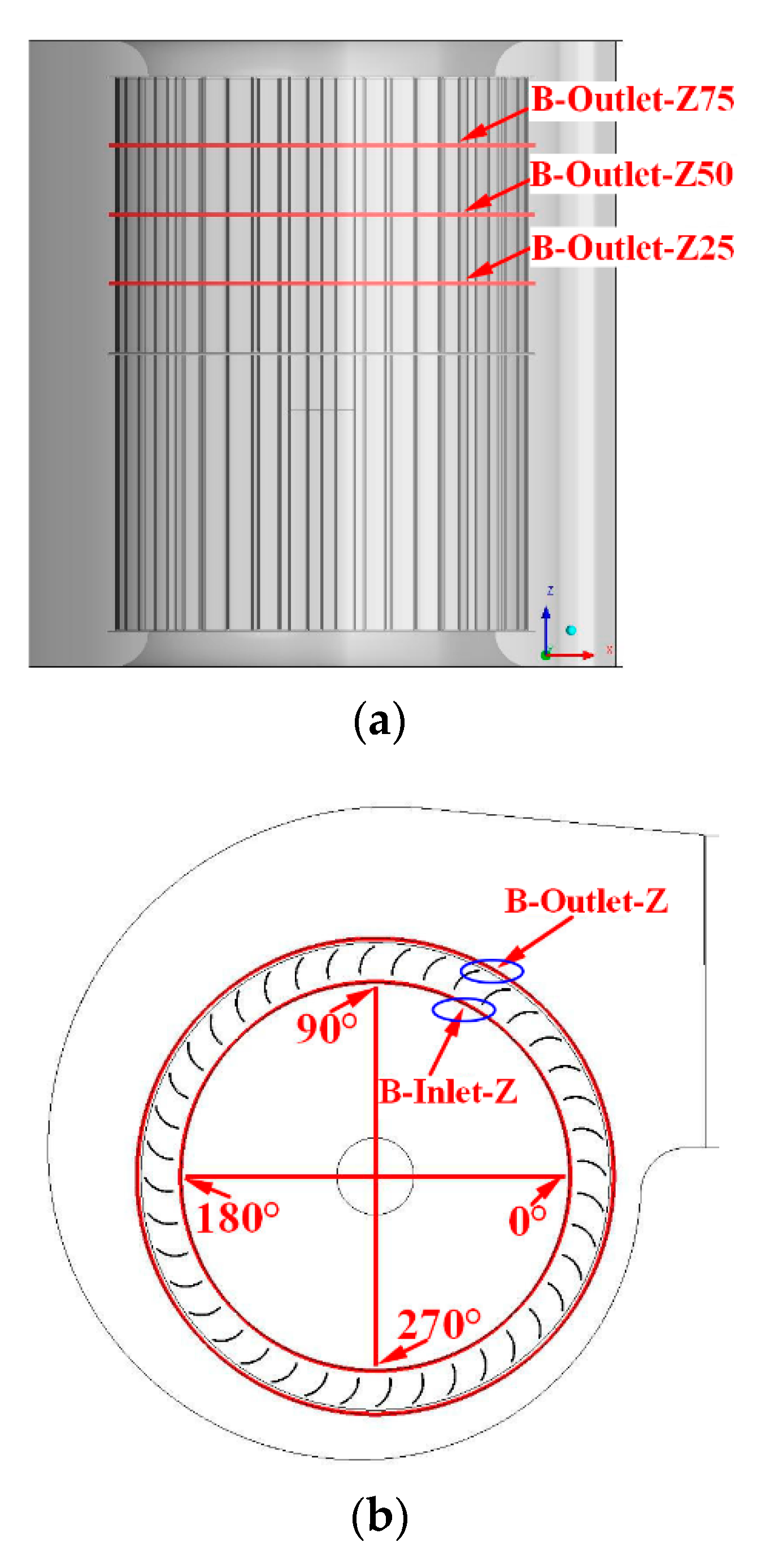
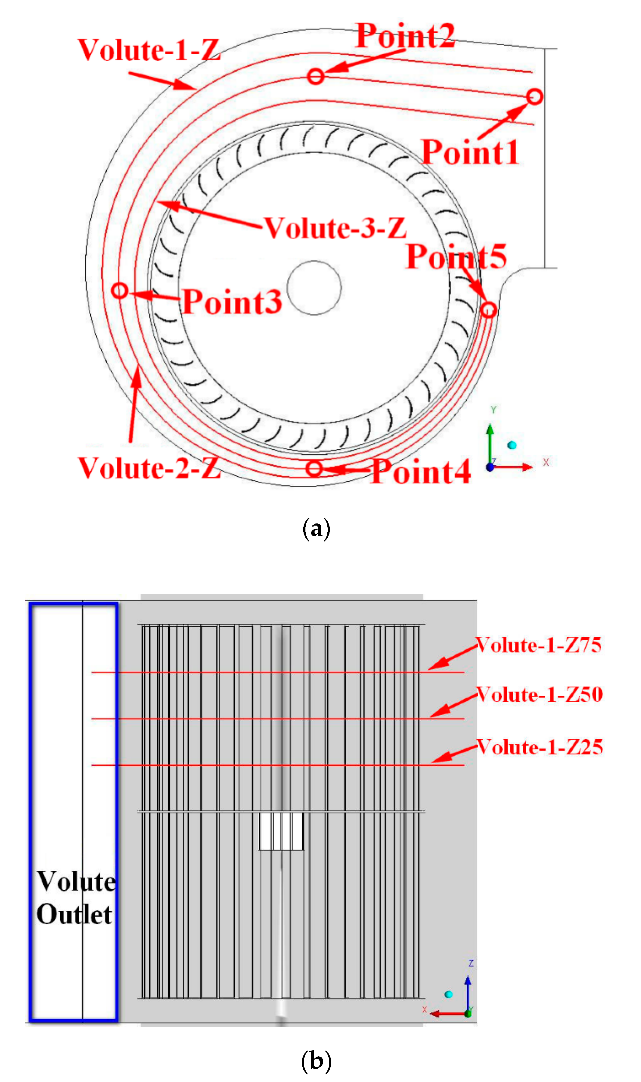
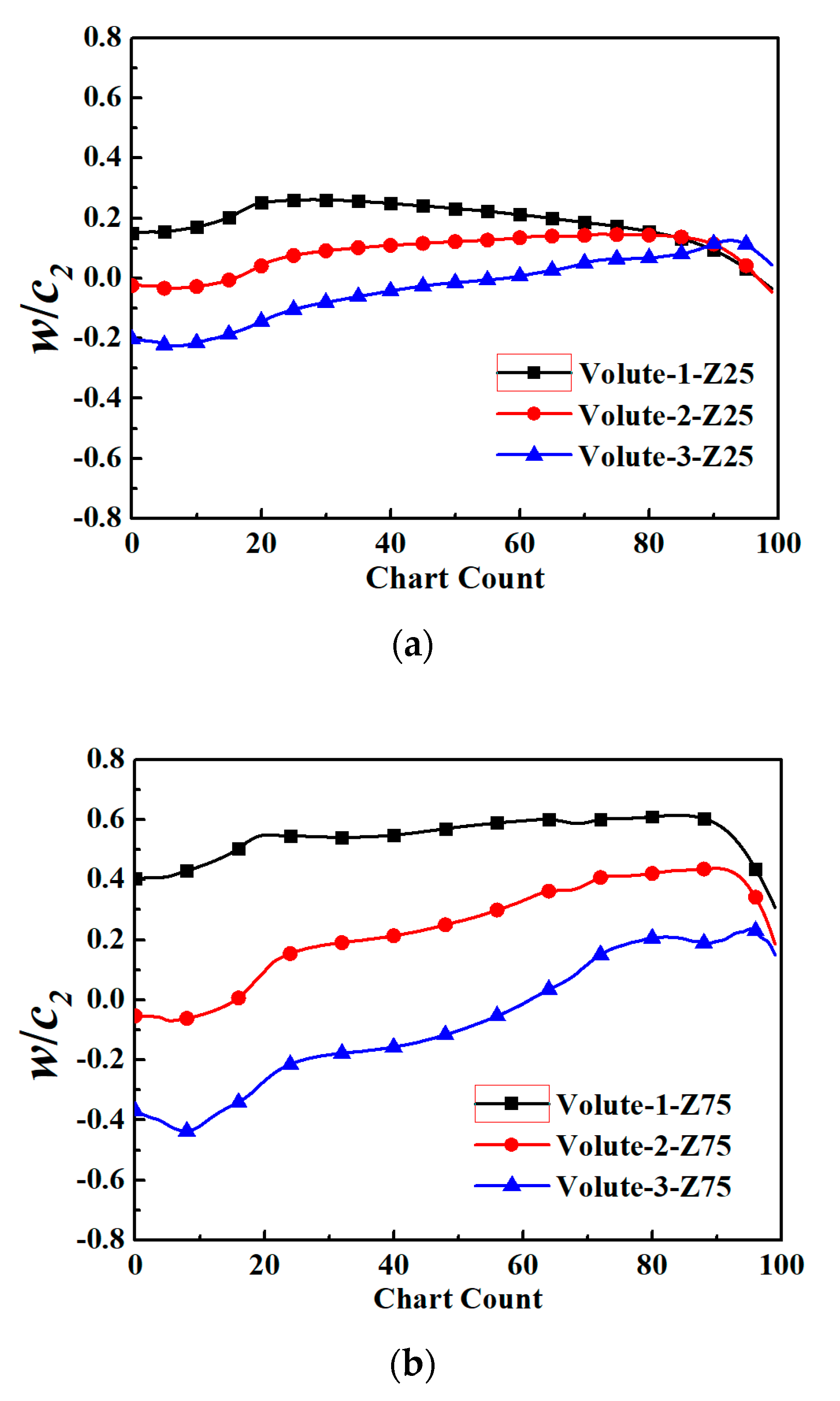
4.3. Flow in the Volute

The flow in the volute is obstructed by the volute outlet vortex. Figure 13 illustrates the staggered flow in the volute. As illustrated in Figure 13, it is obviously observed that the airflow near the upper wall of the volute (solid line) flows from the center to both sides of the volute, while the flow near the impeller (dashed line) shows the opposite trend. This phenomenon is due to the large axial velocity of the flow in blade passage and the low velocity in volute outlet vortex.
As shown in Figure 14a, the flow in the volute is divided into four parts by three curves. The curves are located in the volute between the volute and the impeller. The axial position of the curves are shown in Figure 14b.
Figure 15 describes the distribution of w along the line in volute. Chart Count means that the line segment is divided into 100 equal parts, where 0 is near the exit of the volute and 100 is near the tongue. The velocity w at the Z25 section is smaller than that at the Z75, and there is no great difference in the velocity direction. This shows that the vortex near volute outlet region keeps the axial velocity direction of the flow near the volute tongue consistent.

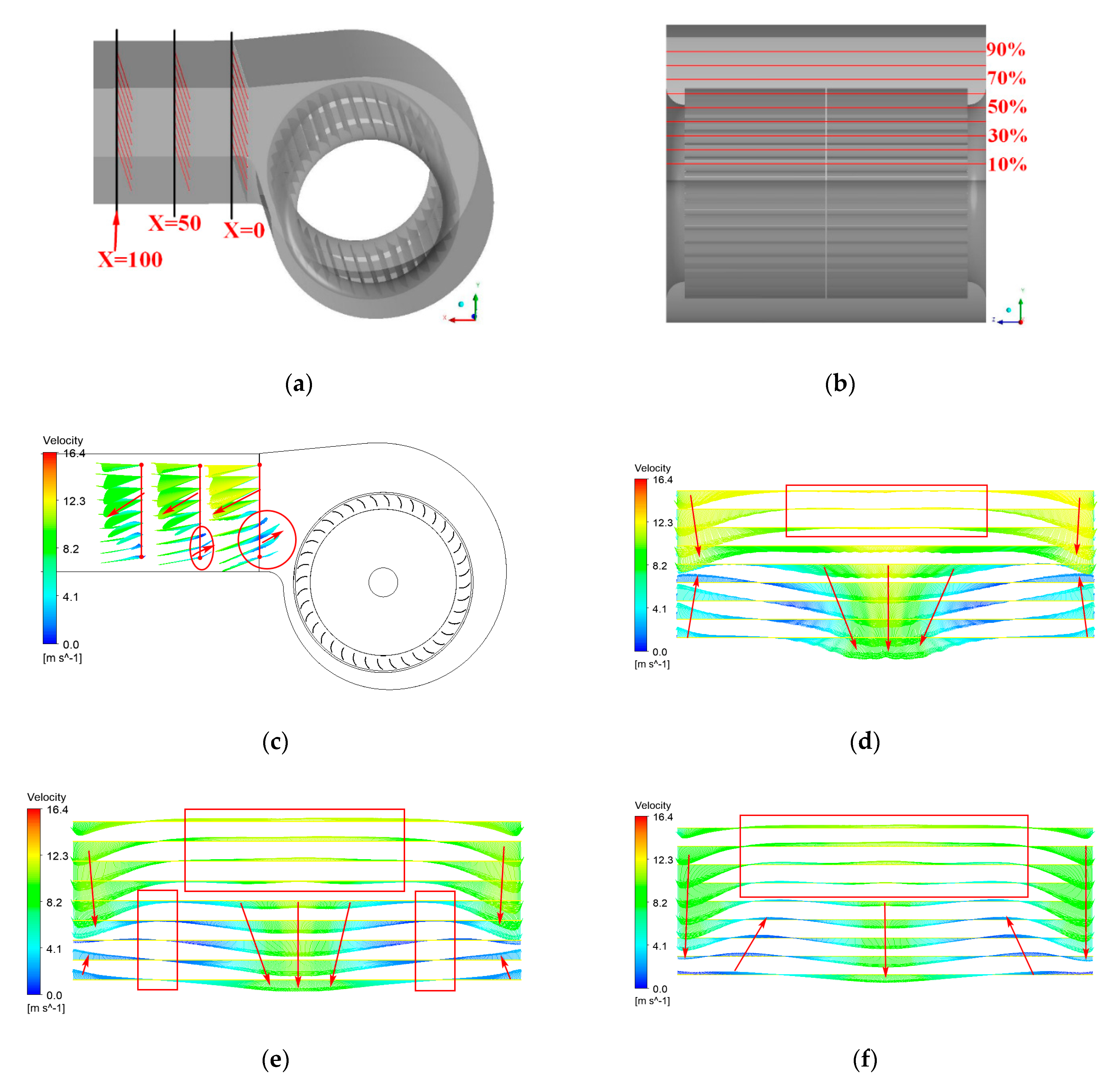
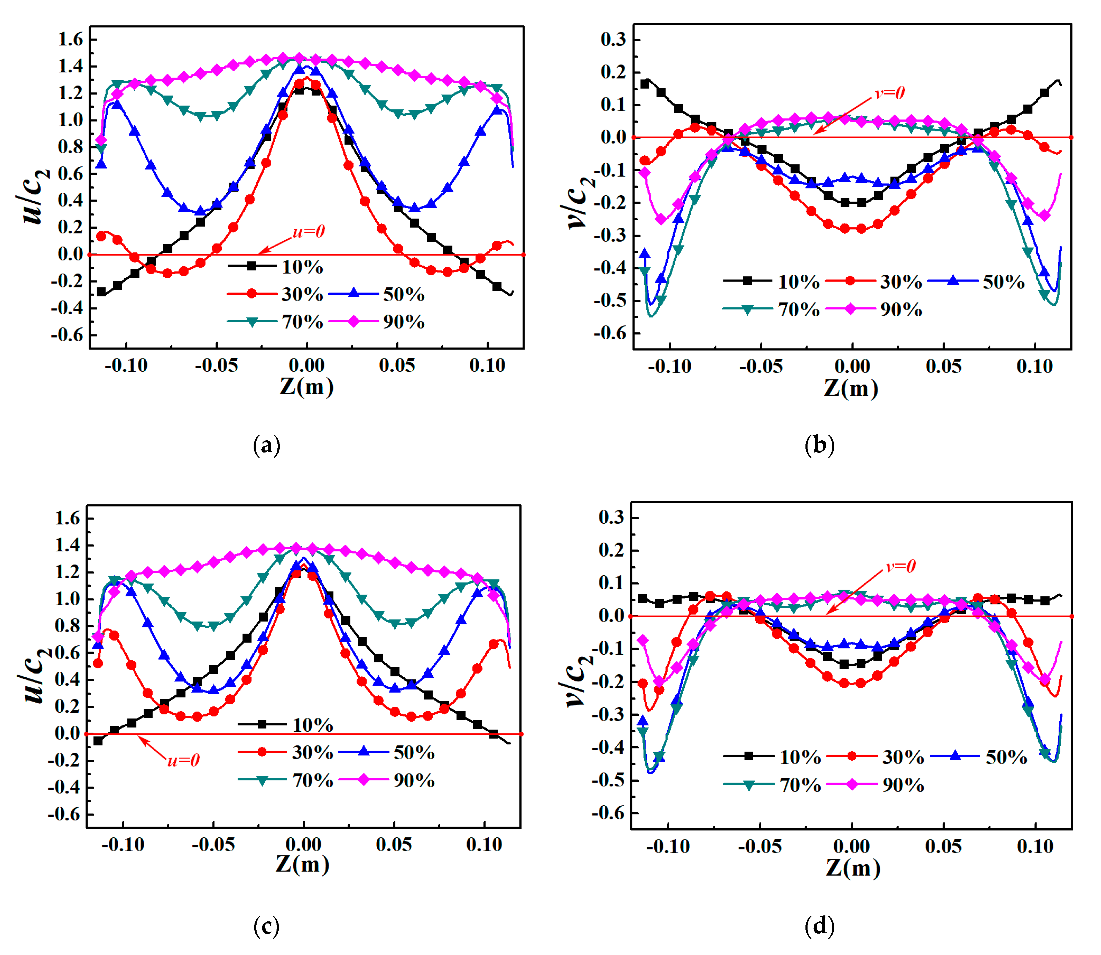
4.4. Outlet Extension Flow Structure

Figure 16 shows the velocity vector from volute outlet to the outlet extension of fan. There are three sections in the outlet extension where X = 100 (X100) means the section is 100 mm away from the volute outlet. As described in Figure 16c, one can see that a number of backflows occur from X = 0 to X = 50 at 10% to 40% height, and the flow from top to bottom can be seen at X = 0 to X100. It is also found that the flow with velocity component in the Y-axis direction (v) is blocked by the volute outlet vortex in Figure 16c. However, it is observed that not all positions have a large v-component velocity at the X = 0 in Figure 16d. It is obviously observed that the air flow converges towards the center of the passage below 50% height in Figure 16e. This mainly indicates that the effect of axial velocity has been continuous from impeller to the volute, which causes the shear friction. It is further obtained that the backflow decreases gradually with increasing x near the volute outlet.
Figure 17 displays the velocity distribution on the line of X = 50 and X = 100. As illustrated in Figure 17, it is obviously observed that the back-flow below occurs at X = 0 50% of the volute outlet height, however, the back-flow disappears at the X = 100. It can be observed that the velocity distribution at 90% height is relatively uniform, but from 70% height all the way to the bottom of the outlet extension section, the air flow is uneven. The velocity at both ends of the line are well consistent with the higher speed zone in the middle of the line segment, which indicates that the volute outlet vortexes are not close to the wall of the extended section. The flow is not the farther away from the volute outlet the better, but the entire area where the vortex outlet vortex exists, the air flow is very chaotic due to the existence of the vortex outlet vortex.

5. Conclusions

In this paper, the complex vortex structure at the volute outlet of a multi-blade fan is investigated by numerical simulation. It is clearly observed that the vortex structure between outlet channel and volute. The effect of channel on the internal flow and performance of multi-blade fan cannot be ignored. The main conclusions are as follows:
First of all, it can be clearly obtained that the streamlines are divided into two parts (backflow and outflow) at the volute outlet. The air flow has a large axial velocity before and after entering the blade flow channel. The airflow is far away from the lobes near the inlet side of volute, and an obvious backflow and step-like barrier structure mainly occur in this area, which leads to the appearance of the vortex at the outlet of the volute.
In addition, the flow vortex at the outlet of the volute causes the airflow of the impeller close to the volute to return to the blade channel. The secondary flow close to the impeller flows from the center to the sides of the volute.
What’s more, it can be observed that the air flow converges towards the center of the passage below 50% height. This mainly indicates that the effect of axial velocity is continuous from impeller to the volute and causes the shear friction. It is further obtained that the backflow gradually decreases with increasing x near the volute outlet.
Finally, the origins and effects of the complex flow structure on the volute outlet are mainly investigated in this work. To benefit more from the vortex structure on the volute outlet, the volute and tongue can be further studied to achieve better flow quality and higher aerodynamic performance of multi-blade centrifugal fan.

Author Contributions

The following statements could be used Y.W. and Z.L. conceived and designed the experiments; X.Y. performed the experiments; Y.W. and Z.L. analyzed the data; Z.L. wrote the paper. All authors have read and agreed to the published version of the manuscript.

Funding

This works were mainly supported by the National Natural Science Foundation of China (11872337, 51906223) and Fundamental Research Funds of Zhejiang Sci-Tech University (2019Y004), the Key Research and Development Program of Zhejiang Province (2020C04011) and Public Projects of Zhejiang Province (LGG20E060001), respectively.

Conflicts of Interest

The authors declare no conflict of interest

References

  1. Kind, R.J.; Tobin, M.G. Flow in a Centrifugal Fan of the Squirrel-Cage Type. J. Turbomach. 1990, 112, 84–90. [Google Scholar] [CrossRef]
  2. Ohta, Y.; Outa, E.; Tajima, K. Evaluation and Prediction of Blade-Passing Frequency Noise Generated by a Centrifugal Blower. J. Fluids Eng. 1996, 118, 597–605. [Google Scholar] [CrossRef]
  3. Ballesteros, T.R.; Francisco, G.C.; Sandra, V.S. Numerical Model for the Unsteady Flow Features of a Squirrel Cage Fan. In Proceedings of the ASME 2009 Fluids Engineering Division Summer Meeting, Vail, CO, USA, 2–6 August 2009. [Google Scholar]
  4. Velarde, S.S.; Ballesteros, T.R.; González, P.J. Numerical simulation of the unsteady flow patterns in a smallmulti-blade fan. Am. Soc. Mech. Eng. 2006, 47519, 297–304. [Google Scholar]
  5. Lin, S.C.; Huang, C.L. An integrated experimental and numerical study of forward-curved centrifugal fan. Exp. Therm. Fluid Sci. 2002, 26, 421–434. [Google Scholar] [CrossRef]
  6. Wang, K.; Ju, Y.P.; Zhang, C.H. Design of multi-blade centrifugal fan based on grouping model and bionic volute tongue. J. Eng. Thermophys. 2017, 38, 1671–1675. [Google Scholar]
  7. Adachi, T.; Sugita, N.; Yamada, Y. Study on the performance of a sirocco fan (optimum design of blade shape). Int. J. Rotating Mach. 2001, 7, 405–414. [Google Scholar] [CrossRef]
  8. Adachi, T.; Sugita, N.; Yamada, Y. Study on the performance of a sirocco fan (flow around the runner blade). Int. J. Rotating Mach. 2004, 10, 415–424. [Google Scholar] [CrossRef] [Green Version]
  9. Darvish, M.; Frank, S.; Paschereit, C.O. Numerical and experimental study on the tonal noise generation of a radial fan. J. Turbomach. 2015, 137, 101005. [Google Scholar] [CrossRef]
  10. Wei, Y.; Ying, C.; Xu, J.; Cao, W.; Wang, Z. Effects of Single-arc Blade Profile Length on the Performance of a Forward multi-blade Fan. Processes 2019, 7, 629. [Google Scholar] [CrossRef] [Green Version]
  11. Wang, K.; Ju, Y.; Zhang, C. Experimental and numerical investigations on effect of blade trimming on aerodynamic performance of squirrel cage fan. Int. J. Mech. Sci. 2020, 177, 105579. [Google Scholar] [CrossRef]
  12. Kind, R.J. Prediction of flow behavior and performance of multi-blade centrifugal fans operating at medium and high flow rates. J. Fluids Eng. 1997, 119, 639–646. [Google Scholar] [CrossRef]
  13. Velarde, S.S.; Ballesteros, T.R.; Santolaria, M.C. Unsteady flow pattern characteristics downstream of a forward-curved blades centrifugal fan. J. Fluids Eng. 2001, 123, 265–270. [Google Scholar] [CrossRef]
  14. Wen, X.; Mao, Y.; Yang, X. Design method for the volute profile of a squirrel cage fan with space limitation. J. Turbomach. 2016, 138, 081001. [Google Scholar] [CrossRef]
  15. Lun, Y.X.; Lin, L.M.; He, H.J.; Zhu, Z.C.; Wei, Y.K. Effects of Vortex Structure on Performance Characteristics of a multi-blade Fan with Inclined tongue. Proc. Inst. Mech. Eng. Part A J. Power Energy 2019, 233, 1007–1021. [Google Scholar] [CrossRef]
  16. Yang, H.; Yu, P.Q.; Xu, J.; Ying, C.L.; Wen, B.C.; Wei, Y.K. Experimental investigations on the performance and noise characteristics of a forward-curved fan with the stepped tongue. Meas. Control 2019, 52, 1480–1488. [Google Scholar] [CrossRef] [Green Version]
  17. Heo, M.W.; Kim, J.H.; Seo, T.W. Aerodynamic and aeroacoustic optimization for design of a forwardcurved blades centrifugal fan. Proc. Inst. Mech. Eng. Part A J. Power Energy 2016, 230, 154–174. [Google Scholar] [CrossRef]
  18. Kim, J.S.; Jeong, U.C.; Kim, D.W. Optimization of sirocco fan blade to reduce noise of air purifier using a metamodel and evolutionary algorithm. Appl. Acoust. 2015, 89, 254–266. [Google Scholar]
  19. Huang, C.H.; Hung, M.H. An optimal design algorithm for centrifugal fans. Theoretical and experimental studies. J. Mech. Sci. Technol. 2013, 27, 761–773. [Google Scholar] [CrossRef]
  20. Khalkhali, A.; Farajpoor, M.; Safikhani, H. Modeling and multi-objective optimization of forward-curved blade centrifugal fans using CFD and neural networks. Trans. Can. Soc. Mech. Eng. 2011, 35, 63–79. [Google Scholar] [CrossRef]
  21. Wang, K.; Ju, Y.; Zhang, C. Numerical investigation on flow mechanisms of squirrel cage fan. Proc. Inst. Mech. Eng. Part A J. Power Energy 2018. [Google Scholar] [CrossRef]
  22. Meneveau, C.; Lund, T.S.; Cabot, W.H. A Lagrangian Dynamic Subgrid Scale Model of Turbulence. J. Fluid Mech. 1996, 319, 353–385. [Google Scholar] [CrossRef] [Green Version]
  23. Piomelli, U. High Reynolds Number Calculations Using The Dynamic Subgrid Scale Stress Model. Phys. Fluids 1993, 5, 1484–1490. [Google Scholar] [CrossRef]
  24. Wang, C.; Hu, B.; Zhu, Y.; Wang, X.; Luo, C.; Cheng, L. Numerical study on the gas-water two-phase flow in the self-priming process of self-priming centrifugal pump. Processes 2019, 7, 330. [Google Scholar] [CrossRef] [Green Version]
  25. Wang, Z.D.; Wei, Y.K.; Qian, Y.H. A bounce back-immersed boundary-lattice Boltzmann model for curved boundary. Appl. Math. Model. 2020, 81, 428–440. [Google Scholar] [CrossRef]
Figure 1. Three-dimensional model of a multi-blade fan: (a) the multi-blade fan manufacture; (b) schematic diagram of the multi-blade fan.
Processes 08 01240 g001
Figure 2. Sketch of the test installation. 1: Testing room, 2: Soundproof room, 3: Reflective wall, 4: Fan installation location, 5: Negative pressure chamber, 6: Positive pressure chamber, 7: Flow return room, 8: Inlet duct, 9: Outlet duct, 10: Silencer, 11: Muffler spike, 12: Testing fan, 13 Auxiliary fan, 14 Flow adjustment device, 15: Multiple nozzles, 16: Chip muffler, 17: Pressure taps in front of nozzle, 18: Pressure taps position behind the nozzle, 19: Pressure taps, 20: Noise taps, 21: Pressure taps, 22: Noise taps.
Processes 08 01240 g002
Figure 3. Negative pressure chamber.
Processes 08 01240 g003
Figure 4. Computational domain and coordinate: (a) computational domain of fan; (b) coordinate and origin.
Processes 08 01240 g004
Figure 5. Total pressure with grid number.
Processes 08 01240 g005
Figure 6. The grid of fan: (a) the grid of impeller; (b) the grid of volute.
Processes 08 01240 g006
Figure 7. Comparison of experimental and numerical data under different flow rates: (a) total pressure; (b) efficiency.
Processes 08 01240 g007
Figure 8. Streamline diagram with different flow coefficient: (a) φ = 0.435; (b) φ = 0.609; (c) φ = 1.175.
Processes 08 01240 g008
Figure 9. Line B-Outlet in impeller: (a) top view; (b) side view.
Processes 08 01240 g009
Figure 10. Absolute velocity distribution on-line B-Outlet-Z: (a) B-Outlet-Z25; (b) B-Outlet-Z50; (c) B-Outlet-Z75; (d) B-Outlet-(0°–90°).
Processes 08 01240 g010
Figure 11. Streamline of Section S in multi-blade fan: (a) section S in fan; (b) streamline on section S.
Processes 08 01240 g011
Figure 12. Velocity distributions on-line B-Inlet and B-Outlet: (a) Velocity u1 distribution on-line B-Inlet-Z (0°–90°); (b) Velocity u2 distribution on-line B-Outlet-Z (0°–90°); (c) Velocity w1 distribution on-line B-Inlet-Z; (d) Velocity w2 distribution on-line B-Outlet-Z.
Processes 08 01240 g012
Figure 13. Streamline in volute.
Processes 08 01240 g013
Figure 14. Line volute-Z in volute: (a) side view; (b) top view.
Processes 08 01240 g014
Figure 15. Velocity w distribution on-line Volute-Z: (a) won-line Volute Z25; (b) won-line Volute Z75.
Processes 08 01240 g015
Figure 16. Velocity vector on-line X: (a) Line X sketch; (b) different height with X; (c) Velocity vector near volute outlet; (d) Velocity vector on-line X = 0; (e) Velocity vector on-line X = 50; (f) Velocity vector on-line X = 100.
Processes 08 01240 g016
Figure 17. Velocity distribution on-line: (a) Velocity u distribution on-line (X = 50); (b) Velocity v distribution on-line (X = 50); (c) Velocity u distribution on-line (X = 100); (d) Velocity v distribution on-line (X = 100).
Processes 08 01240 g017
Table 1. Design dimensions for the multi-blade fan.
ParameterDimension
Inlet diameter of impeller (D1)132 mm
Outlet diameter of impeller (D2)150 mm
Width of impeller (b)200 mm
Inlet angle of blade (β1)90°
Outlet angle of blade (β2)27°
Blade number40

