


Control Approach of Grid-Connected PV Inverter under Unbalanced Grid Conditions

Department of Electrical Engineering, College of Engineering, King Saud University, Riyadh 11421, Saudi Arabia
Processes 2024, 12(1), 212; https://doi.org/10.3390/pr12010212
Submission received: 30 November 2023
/
Revised: 24 December 2023
/
Accepted: 15 January 2024
/
Published: 18 January 2024
(This article belongs to the Special Issue AC and DC Power Grids System Technologies: Analysis, Control and Practical Applications)
Abstract
:In grid-connected photovoltaic (PV) systems, power quality and voltage control are necessary, particularly under unbalanced grid conditions. These conditions frequently lead to double-line frequency power oscillations, which worsen Direct Current (DC)-link voltage ripples and stress DC-link capacitors. The well-known dq frame vector control technique, which is effective under normal conditions, struggles with oscillatory component management in unbalanced grid conditions. To address this issue, this paper presents an advanced control approach designed for grid-connected PV inverters. The proposed approach is effective at reducing oscillations in the DC-link voltage at double the grid frequency, thereby enhancing system stability and component longevity. This method introduces a feedback control method designed to regulate oscillatory components that appeared within the dq frame and suppress the DC-link voltage oscillations under imbalance conditions, including single line-to-ground (SLG) faults. Additionally, the control scheme incorporates a maximum power point tracking (MPPT) controller to optimize PV efficiency. Comprehensive simulations demonstrate the effectiveness of this method in maintaining sinusoidal current injections and stabilizing DC-link voltage during unbalanced grid conditions. Simulation results show that the control scheme effectively stabilizes DC-link voltage, maintains balanced grid current, and ensures constant active power under various conditions, including SLG faults and solar irradiance changes.
1. Introduction
The beginning of renewable energy sources, particularly photovoltaic (PV) systems, has marked a significant shift in the global energy landscape. Grid-connected PV systems have become increasingly widespread due to their sustainable nature and declining costs. These systems play a crucial role in the electrical grid by interfacing PV arrays and the distribution network. However, their integration into the power grid is not without challenges, especially under unbalanced grid conditions, which can significantly impact the performance and longevity of the system components [1,2,3].
Voltage imbalances in the grid are common occurrences resulting from asymmetrical loads or faults in the system. These unbalances lead to voltage sags, fluctuations, and disturbances that can adversely affect grid-connected PV systems [4,5,6]. The primary component that suffers under these conditions is the power converter, which is responsible for converting the variable Direct Current (DC) output of the PV array into a stable Alternating Current (AC) output compatible with the grid. Under conditions of grid imbalance, active power experiences oscillations at twice the line frequency, which in turn leads to oscillations in the DC-link voltage. This phenomenon increases the stress on DC-link capacitors, potentially reducing their lifespan as well as the overall reliability of the power conversion unit [7,8,9]. Research has primarily focused on developing control strategies that can mitigate these oscillations, thereby enhancing the reliability and efficiency of grid-connected PV systems. The common approach has been the use of negative sequence current components to cancel out the active power oscillation, a method that has shown potential in reducing DC-link capacitor stresses during voltage sags [10,11,12]. However, the challenge of controlling these oscillations in the DC-link voltage under conditions of grid imbalance remains challenging. Conventional methods of vector control within the dq reference framework, typically employed for managing current in inverter applications, face difficulties in managing oscillatory components under unbalanced grid voltages [13,14]. This inadequacy necessitates the exploration of novel control strategies that can effectively address the unique challenges posed by unbalanced grid conditions. The literature reveals a scope of work focusing on the operation of grid-connected converters during unbalanced conditions, contributing insights on flexible control strategies, dynamic saturation schemes to limit output current, and strategies to reduce stress on DC-link capacitors [15,16,17,18]. These approaches do not provide a comprehensive solution to the problem of DC-link voltage oscillation during unbalanced grid conditions. For instance, methods for current reference generation during grid faults can result in output currents with harmonics under unbalanced grid conditions, which is not ideal for system stability and efficiency [10,19].
Maximum Power Point Tracking (MPPT) algorithms are essential for ensuring optimal energy generation from PV systems, especially under varying environmental conditions. The MPPT algorithms ensure that the PV array operates at its maximum power point, which is vital for the overall efficiency and effectiveness of the power generation process [20]. Various MPPT strategies have been explored in literature, including classical methods like Perturb and Observe (P&O), Hill Climbing (HC), and Incremental Conductance (INC) [20,21,22,23,24,25,26]. P&O and HC are simpler to implement, while INC is more accurate and adaptable to changing atmospheric conditions but is complex in terms of simulation and experimental implementation. Advanced techniques such as Fuzzy Logic Control (FLC) and Artificial Neural Networks (ANN) have also been developed [27,28]. However, FLC requires expert knowledge and intricate rule-based system design, and ANN requires extensive data for accurate training.
Several studies have proposed methods to deal with both positive and negative sequence currents to mitigate the grid voltage’s negative sequence [29,30,31,32]. However, these methods include oscillatory components in both active and reactive power when the grid is in an unbalanced condition [33]. Even more challenging is the control of these oscillations in systems where the DC-link voltage is not constant, which is a common scenario in unbalanced grid conditions. Thus, there is a demand for a control approach capable of managing the fluctuations in the DC-link voltage while at the same time ensuring efficient power regulation [34,35,36]. The control of both active power and reactive power for grid balance of the PV system under a grid fault has been a subject of research with various strategies being proposed. These include Fault Ride Through (FRT) solutions that enhance the reliability of the grid-connected inverters’ ride-through capabilities by allowing for the simultaneous injection of components of active and reactive power/current in both positive and negative sequences [37,38]. However, these methods do not provide sufficient control freedom for the simultaneous elimination of power oscillations and current harmonics, particularly in systems involving three-phase, three-wire grid-connected inverters [39]. To address these shortcomings, advanced control algorithms based on symmetric sequences have been developed [40,41,42,43]. These techniques are designed to fulfill distinct control targets relating to current harmonics, fluctuations in power, DC-link voltage variations, and maintaining voltage stability during conditions of grid imbalance. Despite these advancements, the problem of excessive and harmonic current during instances of FRT under unbalanced grid conditions, which influences the reliability of system’s operation, remains unresolved. The power oscillations that arise in such scenarios can disrupt the provision of power in systems that rely on inverters, posing a significant challenge to the stability and efficiency of the power grid.
Given these challenges, this paper aims to develop a novel control strategy for grid-connected PV inverters under unbalanced grid conditions. This approach emphasizes reducing the oscillations that occur at twice the grid frequency within the DC-link voltage while maintaining a sinusoidal grid current with minimal harmonics. This aspect is crucial for maintaining both the operational stability and the extended lifespan of inverter element and PV systems. The approach involves a feedback control method to regulate oscillatory components within the dq reference frame and suppress ripples in the DC-link voltage under unbalanced grid conditions. Additionally, the control scheme incorporates an MPPT based on the P&O algorithm, optimizing the efficiency of the PV array.
2. System Structure
The diagram in Figure 1 presents the architecture of a three-phase PV system interconnected with the grid, which is the subject of investigation in this research. The core of this system is a single-stage inverter, typically a three-phase inverter, that plays several critical roles. Its primary role is involved with harnessing the maximum possible power from the PV farm, which is achieved using an MPPT algorithm. Besides power optimization, the inverter is also designed to execute power curtailment during instances of voltage sags. Voltage sags can occur due to faults in the grid or sudden large loads. The ability to curtail power protects the inverter and the grid from potential damage that could be caused by these disturbances, ensuring a more resilient energy system. Furthermore, the inverter is responsible for injecting the generated power into the electrical grid. This injection must be synchronized with the grid in terms of voltage magnitude, frequency, and phase. To interface the inverter with the grid, an LCL filter is employed. This filter consists of two inductors (Lf and Lg), one capacitor (Cf), and one resistor (Rd), forming an LCL configuration, which serves to attenuate the switching harmonics generated by the inverter’s Pulse Width Modulation (PWM) control. The use of PWM is an advanced control strategy that modulates the inverter’s output, providing precise control over the voltage and current waveforms. The LCL filter thereby ensures that the power quality of the injected electricity meets grid standards, minimizing harmonic distortion and improving the system’s overall electromagnetic compatibility. At the final stage, a three-phase transformer is employed to step-up the voltage to the appropriate level of the distribution grid system. This step-up process is essential, as the voltage generated by the PV system is typically lower than that required for the distribution grid. The transformer also provides galvanic isolation, separating the PV inverter electrically from the grid, adding an extra layer of safety, and improving the system’s fault tolerance.
3. Control Strategy under Unbalanced Grid Conditions
The dq transformation, also known as Park’s transformation, is a mathematical technique used to simplify the analysis of three-phase power systems by converting three-phase variables into two components. This transformation is particularly useful in the current control systems of grid-connected PV inverters. This technique converts the three-phase system of AC voltages and currents, which are inherently sinusoidal and phase-shifted by 120 degrees, into two orthogonal components, denoted as d (direct) and q (quadrature). These components can be visualized as vectors rotating in a plane at the same angular frequency (e.g., ω) as the AC grid but transformed into a synchronous rotating frame of reference, simplifying the dynamic model of the electrical system. The synchronization of the dq reference frame with the grid is achieved through a phase-locked loop (PLL) circuit [44,45,46]. The PLL locks onto the grid frequency, ensuring that the rotating dq frame is perfectly aligned with the AC voltage grid, allowing for precise and efficient control. By adjusting the q-axis grid voltage to zero (vq = 0), the control system can maintain synchronization even during transient conditions, further enhancing the robustness and reliability of the inverter’s operation. One of the principal benefits of this method is its capability to independently regulate both active and reactive power. This is a significant advantage for grid-connected inverters, enabling more flexible and efficient power management. Active power can be controlled via the d-component, while reactive power is managed through the q-component. This separation of power components enables the system to respond rapidly to changes in grid conditions or power demands, which is vital for maintaining grid stability and efficiency. In terms of computational demand, the transformation simplifies the control algorithm by converting the AC quantities into DC quantities in the rotating reference frame. This conversion reduces the processing power required for complex calculations, allowing for a quicker response time and less intensive use of computational resources. In a balanced grid, the transformation of grid voltages and currents via the dq method results in DC components in the rotating reference frame. However, under unbalanced grid conditions, such as those caused by faults or asymmetric loads, double grid frequency oscillations are superimposed onto the DC quantities in the dq frame. These oscillations must be carefully managed to prevent adverse effects on the power system’s performance. Applying Park’s transformation to a three-phase system of AC voltages and currents, the components of grid voltages and currents within the dq frame are depicted as follows [13]:
where and are the oscillatory components within the d-axis and q-axis of the grid voltages, respectively. and represent the DC components along the d-axis and q-axis of the grid voltages, correspondingly. Similarly, and correspond to the oscillatory components within the d-axis and q-axis of the grid currents, respectively. and are the DC components along the d-axis and q-axis of the grid currents, respectively. The voltages , , and correspond to the peak amplitudes of the voltages in the three-phase grid system., , and correspond to the peak amplitudes of the currents in the three-phase grid system. The variable indicates the phase displacement between the voltage and current, and is the phase angle for phase x, where .
Equations (1) and (2) express how the grid voltages and currents are represented within the dq reference frame as a combination of DC and oscillatory components. In the dq reference frame, the d-axis is orthogonal to the q-axis, with the q-axis lagging the d-axis by 90 degrees. The oscillatory components of both the grid voltages and currents on both the d- and q-axes are characterized by having the same amplitudes but differ in phase by 90 degrees. These components oscillate at a frequency that is double the grid’s fundamental frequency (denoted as 2ω), a phenomenon that only presents under unbalanced grid conditions. Unbalanced conditions occur when the amplitudes of the three-phase grid voltages or currents are not equal, which can be due to various issues such as asymmetric loads or faults within the grid. Under the assumption of a zero initial phase angle for these oscillatory components, the equations for the grid voltages and currents within the dq frame can be expressed as a sum of their DC and oscillatory components as follows [13]:
In Equation (3), represents the instantaneous value of the d-component, which comprises a DC part and an oscillatory part that varies sinusoidally with time at double the grid frequency, shifted by 90 degrees (or radians). Similarly, Equation (4) defines for the q-component, which also includes a DC part and an oscillatory part , which varies sinusoidally with time at double the grid frequency. The term can refer to either voltage () or current (), depending on the context within the equations. The notation is used to denote the amplitude of the oscillatory components of the dq vectors.
The dynamic of the inverter output voltage can be represented within the dq reference frame as follows:
The inverter’s output voltage components in the dq reference frame, and , are expressions that define the relationship between the inverter’s voltages, currents, and the intrinsic properties of the line and filter, such as resistance () and inductance (). Specifically, and are the voltages along the d-axis and q-axis, respectively, that result from the inverter’s operation. The terms and represent the dq components of the grid voltage. The terms and in Equations (5) and (6) account for the coupling between the d- and q-axes due to the inductance and the angular frequency (ω) of the grid voltage.
3.1. Current Control System
The structure of the inner current control (ICC) system is predicated on Equations (5) and (6), as shown in Figure 2. By leveraging the dynamics expressed in these equations, the control system is designed to generate reference output voltages, and , which are the target voltages that the inverter should produce to maintain optimal performance. Once the reference voltages are determined by the control system, these voltages are then transformed from the dq reference frame back into three-phase AC voltages. The three-phase voltages are processed through a PWM technique to drive the inverter’s semiconductor switches, allowing for precise control over the output voltage and current waveforms.
In the ICC system for grid-connected inverters, Proportional-Integral (PI) controllers are widely used due to their simplicity and effectiveness in maintaining a stable system under balanced grid conditions. These controllers are adept at achieving zero steady-state error, meaning that the control system can maintain the current at the desired setpoint without any persistent deviation over time. However, when the grid conditions become unbalanced, the effectiveness of PI controllers reduces. This is due to the introduction of oscillatory components in the d-axis and q-axis components of the grid currents and voltages. These oscillations, which occur at double the grid’s fundamental frequency, present a control challenge that conventional PI controllers are not designed to handle effectively. The result is an inability to maintain zero steady-state error in the presence of these oscillations, leading to performance issues. To address this deficiency, a resonant controller is introduced alongside the PI controller. The resonant controller is specifically designed to target and control the oscillatory components, those at double the grid frequency, under unbalanced grid conditions.
The control reference signals for the ICC (i.e., and ) are maintained as usual. These reference commands are set to control the dq components of the current, which relate directly to the DC voltage, active power, and reactive power of the system. These reference commands must remain as DC components to ensure the stability of these critical parameters. To effectively suppress the unwanted oscillatory components in the dq grid currents under unbalanced conditions, the reference commands for the oscillatory components, and , are set to zero. Otherwise, these oscillatory components can be used to achieve other goals such as suppressing the active power and DC voltage oscillations under unbalanced conditions, which will be explained in the next sections.
3.2. Constant Power Control
Under conditions of grid balance, the power output typically consists of DC components. However, when the grid becomes unbalanced, the power output is affected by ripples or oscillations. These ripples occur at a frequency that is twice the grid’s fundamental frequency. Thus, active power and reactive power can be expressed in a DC component and an oscillatory component as follows:
where and are the active power DC and oscillatory components, respectively. and are the reactive power DC and oscillatory components, respectively.
Equation (7) summarizes the concept by expressing both active and reactive power as a sum of their DC components (, ) and their oscillatory components (, ). The equation is constructed based on the dq transformation of grid voltages and currents derived in Equations (1) and (2). The power formula, as outlined in Equation (7), can be reformulated to express the DC and oscillatory elements as follows [13]:
In Equation (8), a deeper exploration into the relationship between these power components and the voltage and current vectors in the dq reference frame is depicted. This equation decomposes the power into four terms, each representing a different interaction between voltage and current components. This decomposition shows how the DC and oscillatory components of power are affected by corresponding components of voltage and current. Specifically, the DC components of active and reactive power ( and ) can be controlled by adjusting the DC components of the current ( and ), while the oscillatory components of power ( and ) can be controlled by the oscillatory components of the current ( and ). Equation (8) implies that through precise control of the current’s DC and oscillatory components stabilization of both active and reactive power outputs can be achieved, even under unbalanced conditions. However, challenges arise because the oscillatory current components may not always be lagging by exactly 90 degrees if the oscillatory components of the current ( and ) are independently controlled. This discrepancy can result in harmonic distortions in the output voltages and currents, further complicating the control task. Therefore, to control the active and reactive power, and suppress the active power oscillating with sinusoidal grid currents, the generated reference current commands should be as follows:
where and are the control reference signals for the active and reactive power, respectively. is the oscillatory component reference of the active power, which should be zero (i.e., ) to eliminate the active power oscillation. indicates the time-delay constant of 90 degrees phase displacement between the dq vectors.
Equation (12) shows that the reference command is forced to lag by 90 degrees out of the generated reference command to ensure sinusoidal grid currents. The dq voltages and can also be stated as follows:
Thus, reference command can be calculated from the DC and oscillatory components by implementing a time delay in Equation (11) and subsequently replacing it using Equations (13) and (14) as follows:
Therefore, the generated reference current commands control the active and reactive power and suppress the active power oscillating with sinusoidal grid currents under unbalanced grid conditions.
3.3. Constant DC-Link Voltage Control
In the control system depicted in Figure 3, the PV system’s energy output is carefully regulated to ensure the most efficient conversion and transfer of solar power to the grid. The control system strategy begins with the PV farm voltage and current being processed through an MPPT algorithm, such as the perturb and observe (P&O) method, to determine the optimal DC-link voltage reference (). This optimized voltage reference is essential for maximizing the energy harvested from the solar panels. The active power balance of the system, represented by Equation (16), plays a critical role in maintaining this efficiency, particularly when considering the effects of unbalanced grid conditions that introduce double grid frequency oscillations into the system.
where is the DC-link voltage, is the capacitance of the DC-link capacitor, and is the resistance attached to the DC-link. represents the active power, which consists of both a DC component and an oscillatory component due to the grid’s unbalanced conditions.
Oscillations in the active power, as a result of unbalanced grid conditions, impact the DC-link voltage by inducing oscillations of a similar double grid frequency. From Equation (16), the transfer function can be obtained as follows:
The transfer function models the dynamic relationship between the active power and DC-link voltage . This function provides a mechanism to control the DC-link voltage by adjusting the active power reference . This is accomplished through a control strategy that takes the measured squared DC-link voltage and adjusts it against a commanded squared voltage to stabilize the DC-link voltage. The output of the controller informs the reference for the active power DC and oscillatory components (), which are crucial for mitigating the effects of the DC-link voltage oscillations. Proper active power references ( and ) are generated for Equations (9) and (11) to remove the oscillations within the DC-link voltage.
The control system also employs a decomposition technique to separate the DC and oscillatory components of the grid voltages and currents (as shown in Figure 3). This separation is achieved using cascaded first-order low-pass filters (LPFs). The filters effectively isolate the DC component () and the oscillatory component () of the main signal (). The precision in extracting these components is critical; even a minor phase error can significantly impact the system’s performance. This decomposition technique features a zero-phase error. By ensuring that the magnitude and phase angle of the oscillatory components are accurately determined, the control strategy can effectively manage the oscillations, even under the challenging conditions presented by an unbalanced grid.
4. Simulation Results
A simulation environment, as represented in Figure 4, has been built using MATLAB/SIMULINK R2023a to validate the effectiveness of the suggested control approach. Table 1 shows the parameters of the simulated grid-connected PV inverter system. The performance of the grid-connected PV inverter system is evaluated under SLG fault conditions to validate the proposed control method’s ability to ensure a balanced grid current, constant active power, and constant DC voltage. Furthermore, the dynamic performance of the grid-connected PV inverter system has also been investigated under irradiance variations. The controllers in this system are digitally implemented, operating at a sampling frequency of 19.8 kHz. This frequency is intentionally set to be ten times higher than the system’s switching frequency, ensuring a more precise and effective digital control. The simulation time-step of 5 µs is used in this study.
4.1. Performance of Conventional Control under Grid Imbalance
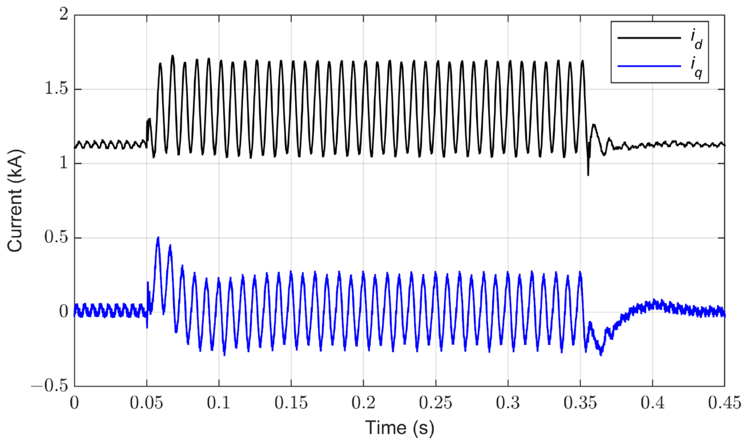
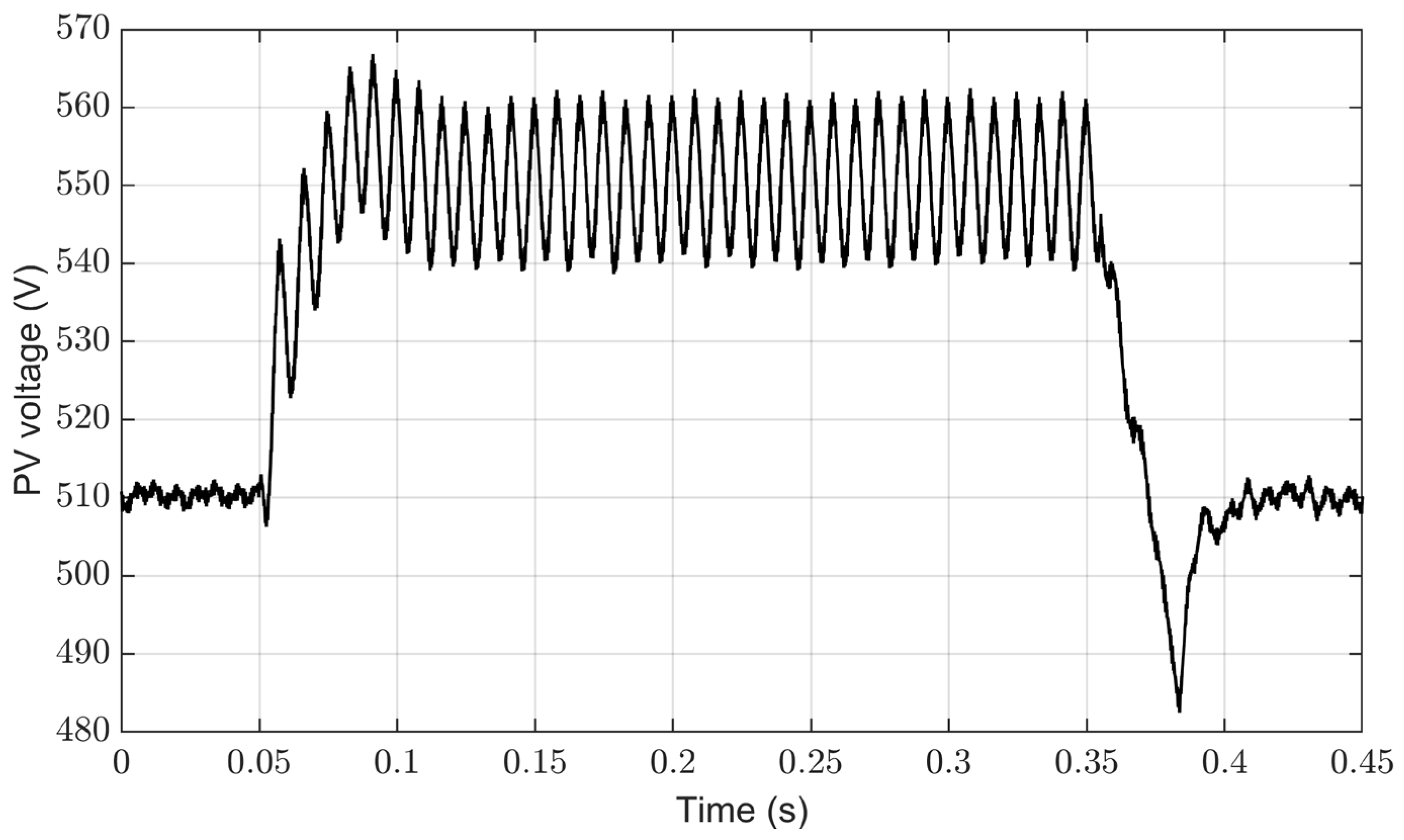
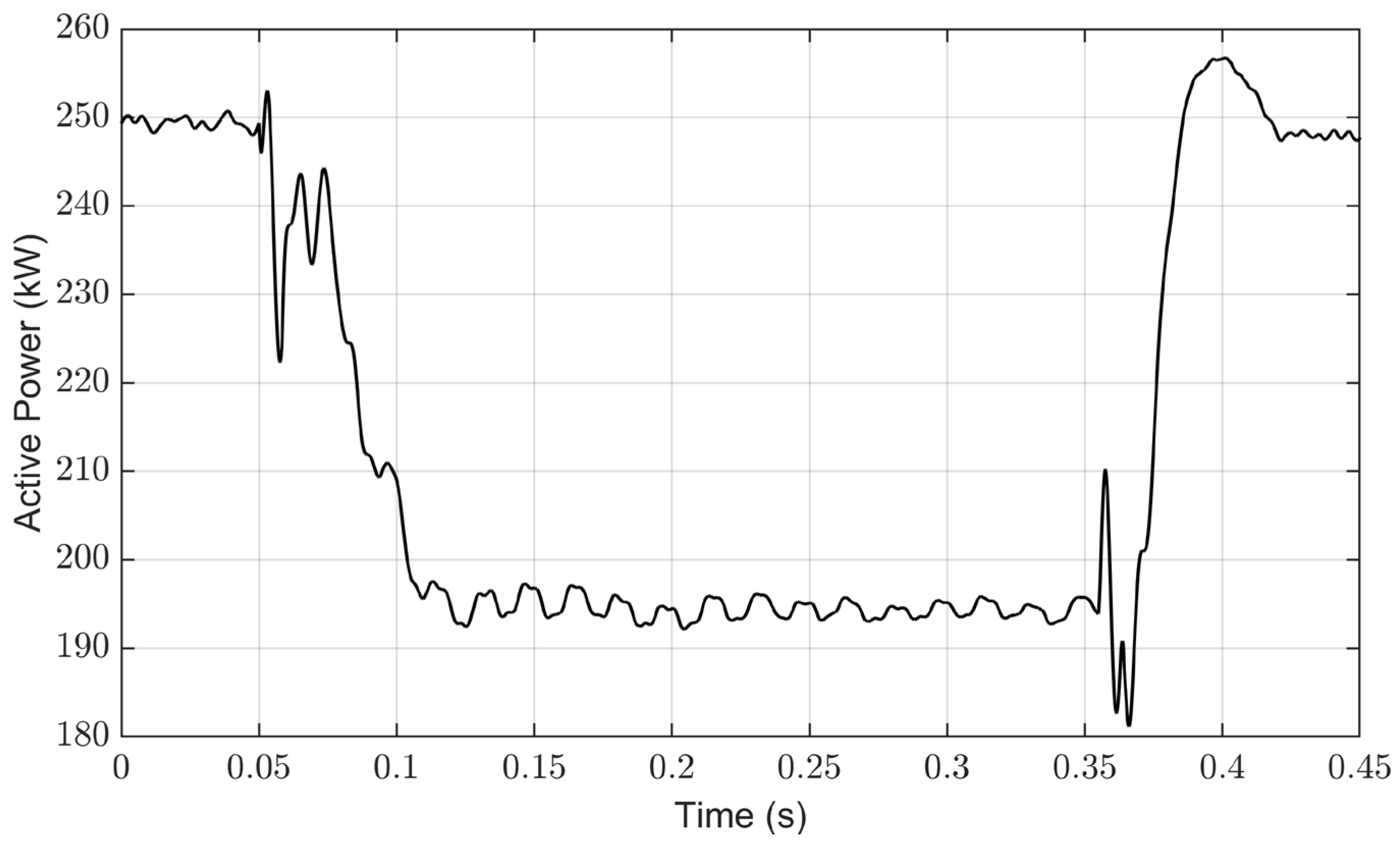
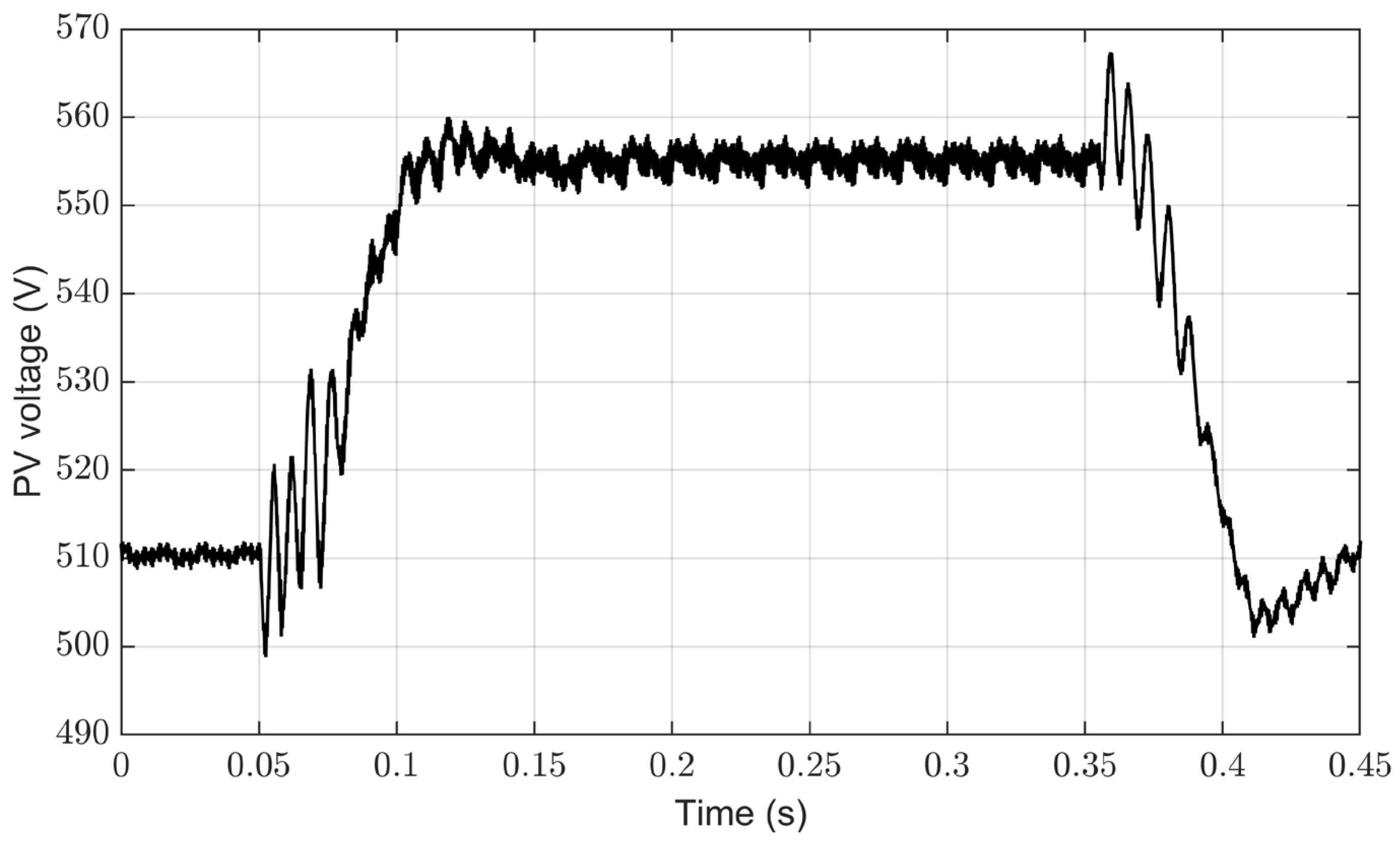
This section investigates the behavior of the conventional control system based on PI controllers during an SLG fault on the AC grid side, occurring between 0.05 s and 0.35 s. The emphasis here is on illustrating the inherent limitations of the conventional control strategy when challenged with such unbalanced grid conditions. Key observations include the imbalance of grid current (Figure 5), the emergence of significant oscillations in the active power (Figure 6), and the development of fluctuations in the DC-link voltage (Figure 7). A notable point of analysis is the demonstration of double grid frequency oscillations within the dq reference frame currents ( and ) and voltages ( and ), a phenomenon uniquely associated with unbalanced grid conditions, as shown in Figure 8 and Figure 9, respectively. The analysis is set with a constant solar irradiance of 1000 W/m2 and a stable temperature of 25 °C. Thus, the maximum power point voltage is maintained at 510.3 V by the MPPT algorithm as shown in Figure 7. The MPPT algorithm generates the PV voltage reference () for the DC-link voltage controller, which eventually maintains the maximum power point of 255.5 kW.
4.2. Performance of Conventional Control for Grid Current Balance
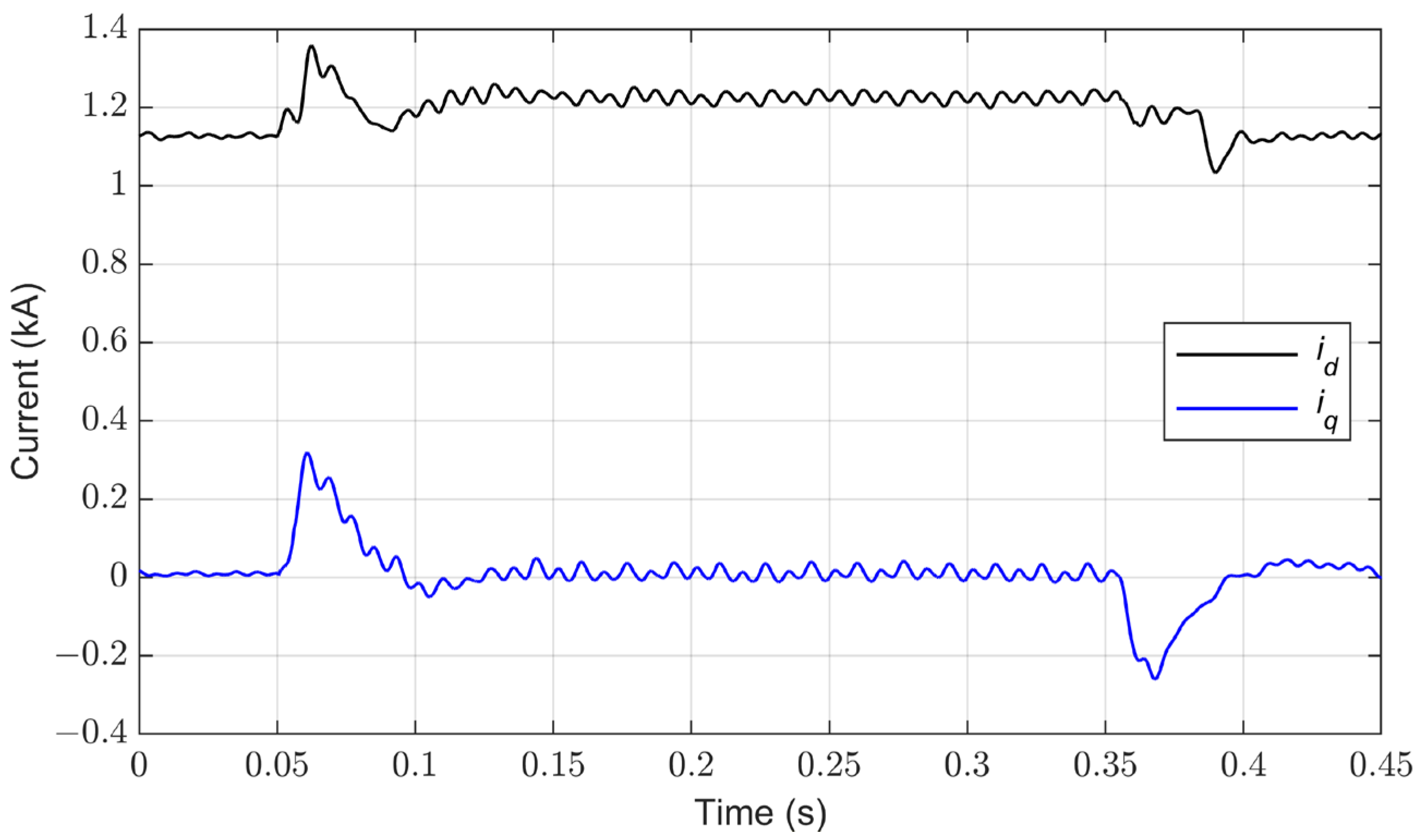
In this part, the proposed control approach is applied to the same fault scenario in the previous section to demonstrate how the control strategy effectively addresses and corrects grid current imbalances. In this case, the dq reference current of oscillatory components ( and ) is set to zero to mitigate the oscillations in the dq currents, as illustrated in Figure 10, which shows the suppression of dq current oscillations during the fault period. This suppression is key to achieving balanced three-phase grid currents, a result clearly depicted in Figure 11.
However, despite these adjustments leading to balanced three-phase currents, the DC-link voltage and active power still exhibit oscillations, as depicted in Figure 12 and Figure 13, respectively. These oscillations, characterized by double the grid frequency, occur under unbalanced grid conditions. Furthermore, an interesting dynamic observed during this process, as shown in Figure 12, is the increase in the DC-link voltage. This increase plays a pivotal role in modulating the power output from the PV array, a relationship that is further explored in Figure 13. The modulation of power output is a strategic response to reduce potential excess power during the fault condition. These oscillations are a critical aspect of our analysis, conducted under constant solar irradiance of 1000 W/m2 and a stable temperature of 25 °C. This controlled environmental setting ensures that the focus remains on the effectiveness of the control strategy in response to grid imbalances, without external variabilities affecting the outcomes.
4.3. Implementation of the Control System for Constant Active Power under Unbalanced Conditions
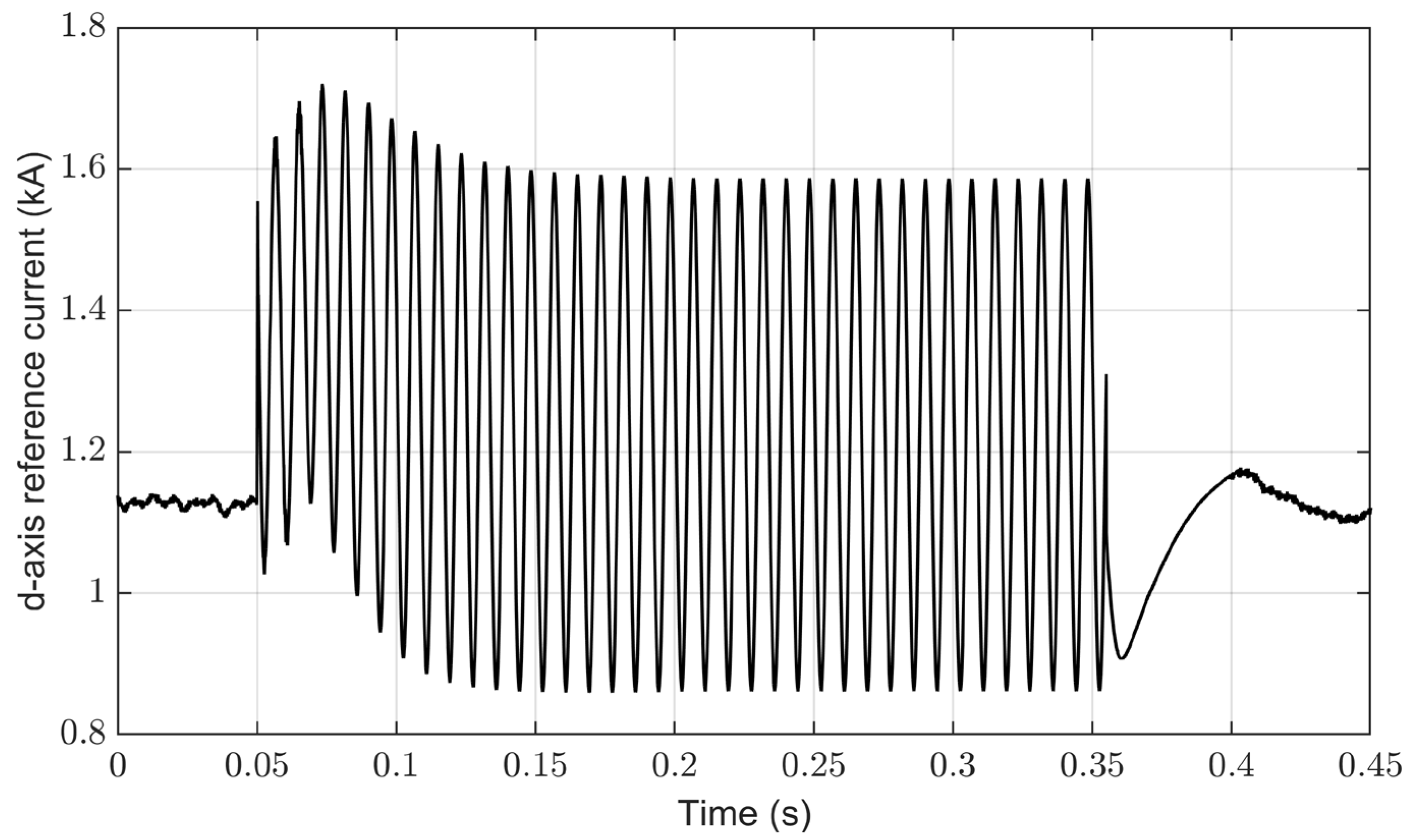
This section explores the ability of the suggested control scheme to stabilize active power during grid imbalances, specifically an SLG fault occurring at 0.05 s and lasting for 300 ms. A key aspect of the proposed system is the nullification of the oscillatory component of the active power reference , coupled with the generation of dq current references ( and ) based on Equations (11) and (15). The effectiveness of this approach is demonstrated in Figure 14, which illustrates a marked suppression of power oscillations compared to prior cases. The control of oscillatory components within the dq currents ( and ), as shown in Figure 15, is pivotal in facilitating this suppression. This mechanism enables the dq currents to manage power fluctuations under fault conditions. Figure 16 shows the generated d-axis current reference of the oscillatory components (), which nullifies the oscillatory component of the active power.
Despite the grid current imbalance caused by the oscillatory components in the dq currents, an interesting phenomenon observed is the sinusoidal nature of the grid current as shown in Figure 17. The oscillatory component of the q-axis current is maintained to always be lagging the d-axis by 90 degrees to ensure a sinusoidal waveform and thus avoid harmonics, as explained in Equation (12). Additionally, the implementation of a current limiter is crucial to maintain current levels within safe operational bounds. This is reflected in the adjustments made to the DC-link voltage, as shown in Figure 18. The increase in DC-link voltage is a strategic measure to control active power and to prevent overproduction of power from the PV array during the fault scenario.
4.4. Implementation of the Control System for Constant DC-Link Voltage under Unbalanced Conditions
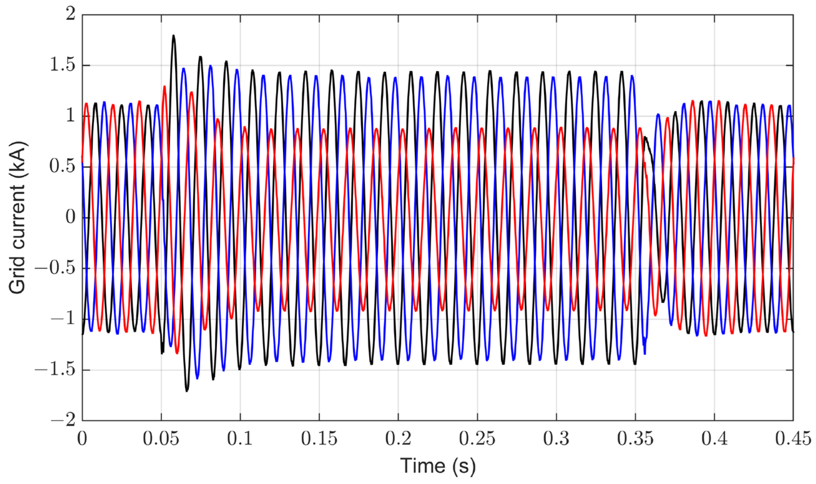
In this section, the focus shifts to managing DC-link voltage oscillations during a grid fault, specifically an SLG fault occurring at 0.05 s and lasting for 300 ms. The use of the proposed control strategy, illustrated in Figure 3, leads to a substantial suppression of the DC-link voltage oscillations. In this case, the oscillatory component of the reference power is used to control the DC-link voltage oscillations, while the oscillatory components of the dq current references are generated based on Equations (11) and (12). The DC-link voltage oscillation is suppressed using a feedback control system, which is a critical improvement over the conventional methods. During the fault, the results show that the DC-link voltage oscillation is significantly suppressed as shown in Figure 19. This suppression is achieved through the control of active power oscillatory components. The active power performance under an imbalance grid fault is shown in Figure 20, highlighting intentional oscillations as per the proposed method. Figure 21 illustrates the generated oscillatory component of the reference power , which plays a pivotal role in mitigating oscillations within the DC-link voltage. Accordingly, the dq currents, exhibiting oscillations as seen in Figure 22, are involved in controlling the active power fluctuations, thereby supporting the suppression of DC-link voltage oscillations. These oscillatory components in dq currents cause the grid current to be unbalanced, but with a sinusoidal waveform, as shown in Figure 23. During the fault, the power is reduced because of the current limiter to keep the current within a reasonable range. Thus, the DC-link voltage (i.e., PV voltage) is increased to reduce the power produced from the PV array. In this case, the solar irradiance on the PV farm is assumed to be constant at 1000 W/m2 and the temperature is 25 °C.
4.5. Performance Evaluation of the Proposed Control System under Irradiance Changes
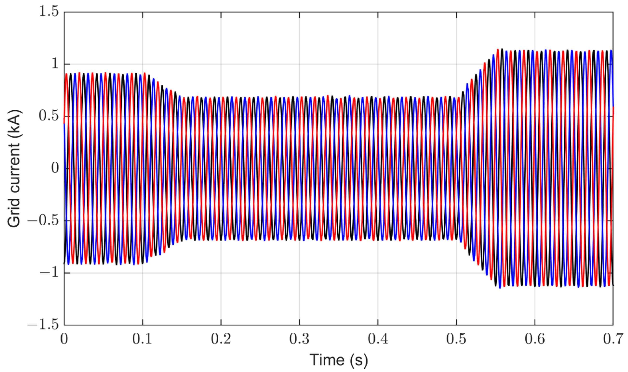
This section assesses the system’s performance under dynamic environmental conditions, particularly changes in solar irradiance. In this case, the temperature is maintained at 25 °C. The power-voltage (P-V) characteristics for the implemented PV farm showing the Maximum Power Point (MPP) at different solar irradiance are illustrated in Figure 24. The solar irradiance on the PV farm is dynamically changed with 800 W/m2, 600 W/m2, and 1000 W/m2 at 0.4 s, 0.7 s, and 1 s, respectively, to validate the robustness and performance of the proposed control system. The solar irradiance change is illustrated in Figure 25. The results show that the MPPT technique is generating a proper maximum power point voltage as a reference for the DC-link inverter control system, and thus the DC-link voltage (i.e., PV voltage) is adjusted at each solar irradiance, shown in Figure 26, to extract the maximum power available. The extracted power at different solar irradiance is shown in Figure 27, aligning with the P-V characteristics and MPP depicted in Figure 24. Furthermore, the impact of varying solar irradiance on the three-phase grid current is presented in Figure 28. The three-phase grid current changes in response to the different levels of solar irradiance, increasing as the irradiance rises and decreasing when the irradiance reduces. This variation in the grid current under different irradiance conditions emphasizes the system’s sensitivity to environmental changes and its ability to adaptively respond, maintaining efficient operation. Table 2 presents a comparison of the calculated and simulated performances of the PV system under varying solar irradiance levels, utilizing the MPPT algorithm. The close alignment between the calculated and simulated values, as evidenced by the minimal error percentages, emphasizes the precision of the MPPT algorithm in governing the PV system’s operation. Notably, under varying irradiance levels (i.e., 600, 800, and 1000 W/m2), the PV inverter with the MPPT technique consistently sustains the system’s operation near its maximum power output. Table 3 describes the performance metrics of the PV inverter system across the same spectrum of solar irradiance levels. The grid-connected PV inverter maintains high efficiency, marked at 98%, 98.4%, and 97.6% for 600, 800, and 1000 W/m², respectively.
5. Limitations and Future Research Plans of the Proposed Control Scheme
While the proposed control scheme for grid-connected PV inverters under unbalanced grid conditions has demonstrated effectiveness in various scenarios, including SLG faults and dynamic changes in solar irradiance, acknowledging certain inherent limitations remains crucial:
- Controllers’ Parameters Design Sensitivity: The performance of the control strategy is heavily dependent on the precise tuning of the controllers’ parameters. This sensitivity could lead to challenges in real-world applications, where exact parameter values may not be consistently attainable or where parameters may need to be adjusted to accommodate varying grid conditions;
- Implementation Complexity in Real-World Settings: Although the scheme has shown promising results in simulations, the real-world implementation might encounter complexities due to factors like hardware limitations, environmental variations, and unanticipated grid disturbances. These factors can affect the control strategy’s performance and reliability;
- Scalability and Adaptability Concerns: The current research primarily focuses on specific grid imbalances. Extending the control strategy to various types and scales of PV systems, and under different grid conditions, requires further exploration to establish its scalability and adaptability;
- Dynamic Environmental Response: The control scheme’s responsiveness to a range of dynamic environmental factors, beyond solar irradiance changes, is not fully explored. Understanding the system’s performance under a broader spectrum of environmental conditions is crucial for its application in diverse geographical and climatic settings.
The above limitations highlight the need for further research and development in these areas. Future work will focus on addressing these limitations through experimental validations, scalability studies, adaptability assessments under various grid and environmental conditions, and comprehensive analysis of parameter robustness and system stability.
6. Conclusions
This paper has examined the challenges and solutions in managing grid-connected PV inverters under conditions of grid imbalance. The paper introduces a novel control scheme that efficiently attenuates the double grid frequency oscillations observed in the DC-link voltage, a common issue under unbalanced grid conditions. The proposed scheme is validated through comprehensive simulations. This strategy includes a feedback control method for regulating oscillatory components within the dq frame, thus suppressing ripples in the DC-link voltage. The integration of an MPPT controller further optimizes the efficiency of the PV array. The proposed control method demonstrates its effectiveness in maintaining sinusoidal current injections and stabilizing DC-link voltage during unbalanced grid conditions to contribute effectively to the power grid even under challenging conditions. The suggested control scheme is considered under various scenarios, including SLG faults and dynamic changes in solar irradiance. The results showed that the system could maintain a balanced grid current, constant active power, and constant DC-link voltage, highlighting the robustness and flexibility of the proposed solution.
Funding
This research was funded by the Deputyship for Research & Innovation, “Ministry of Education” in Saudi Arabia, grant number (IFKSUDR_E141).
Data Availability Statement
Data are contained within the article.
Acknowledgments
The authors extend their appreciation to the Deputyship for Research & Innovation, “Ministry of Education” in Saudi Arabia for funding this research work through the project number (IFKSUDR_E141).
Conflicts of Interest
The author declares no conflict of interest.
References
- Jia, J.; Yang, G.; Nielsen, A.H. A Review on Grid-Connected Converter Control for Short-Circuit Power Provision under Grid Unbalanced Faults. IEEE Trans. Power Deliv. 2018, 33, 649–661. [Google Scholar] [CrossRef]
- Rey-Boué, A.B.; Guerrero-Rodríguez, N.F.; Stöckl, J.; Strasser, T.I. Frequency- Adaptive Control of a Three-Phase Single-Stage Grid-Connected Photovoltaic System under Grid Voltage Sags. Int. J. Electr. Power Energy Syst. 2021, 125, 106416. [Google Scholar] [CrossRef]
- Mishra, M.K.; Lal, V.N. A Multiobjective Control Strategy for Harmonic Current Mitigation with Enhanced LVRT Operation of a Grid-Tied PV System Without PLL under Abnormal Grid Conditions. IEEE J. Emerg. Sel. Top. Power Electron. 2023, 11, 2164–2177. [Google Scholar] [CrossRef]
- De Almeida, J.O.M.B.; Torres, A.G.; Cupertino, A.F.; Pereira, H.A. Three-Phase Photovoltaic Inverters during Unbalanced Voltage Sags: Comparison of Control Strategies and Thermal Stress Analysis. In Proceedings of the 2016 12th IEEE International Conference on Industry Applications (INDUSCON), Curitiba, Brazil, 20–23 November 2016. [Google Scholar] [CrossRef]
- Cupertino, A.F.; Xavier, L.S.; Brito, E.M.S.; Mendes, V.F.; Pereira, H.A. Benchmarking of Power Control Strategies for Photovoltaic Systems under Unbalanced Conditions. Int. J. Electr. Power Energy Syst. 2019, 106, 335–345. [Google Scholar] [CrossRef]
- Meral, M.E.; Çelik, D. Minimisation of Power Oscillations with a Novel Optimal Control Strategy for Distributed Generation Inverter under Grid Faulty and Harmonic Networks. IET Renew. Power Gener. 2020, 14, 3010–3022. [Google Scholar] [CrossRef]
- Afshari, E.; Moradi, G.R.; Rahimi, R.; Farhangi, B.; Yang, Y.; Blaabjerg, F.; Farhangi, S. Control Strategy for Three-Phase Grid-Connected PV Inverters Enabling Current Limitation under Unbalanced Faults. IEEE Trans. Ind. Electron. 2017, 64, 8908–8918. [Google Scholar] [CrossRef]
- Chen, H.C.; Lee, C.T.; Cheng, P.T.; Teodorescu, R.; Blaabjerg, F. A Low-Voltage Ride-Through Technique for Grid-Connected Converters with Reduced Power Transistors Stress. IEEE Trans. Power Electron. 2016, 31, 8562–8571. [Google Scholar] [CrossRef]
- Wang, H.; Blaabjerg, F. Reliability of Capacitors for DC-Link Applications in Power Electronic Converters—An Overview. IEEE Trans. Ind. Appl. 2014, 50, 3569–3578. [Google Scholar] [CrossRef]
- Rodriguez, P.; Timbus, A.V.; Teodorescu, R.; Liserre, M.; Blaabjerg, F. Flexible Active Power Control of Distributed Power Generation Systems during Grid Faults. IEEE Trans. Ind. Electron. 2007, 54, 2583–2592. [Google Scholar] [CrossRef]
- Castilla, M.; Miret, J.; Sosa, J.L.; Matas, J.; Vicuña, L.G. De Grid-Fault Control Scheme for Three-Phase Photovoltaic Inverters with Adjustable Power Quality Characteristics. IEEE Trans. Power Electron. 2010, 25, 2930–2940. [Google Scholar] [CrossRef]
- Wang, F.; Duarte, J.L.; Hendrix, M.A.M. Pliant Active and Reactive Power Control for Grid-Interactive Converters under Unbalanced Voltage Dips. IEEE Trans. Power Electron. 2011, 26, 1511–1521. [Google Scholar] [CrossRef]
- Alharbi, M.; Isik, S.; Alkuhayli, A.; Bhattacharya, S. Power Ripple Control Method for Modular Multilevel Converter under Grid Imbalances. Energies 2022, 15, 3535. [Google Scholar] [CrossRef]
- Montero-Robina, P.; Rouzbehi, K.; Gordillo, F.; Pou, J. Grid-Following Voltage Source Converters: Basic Schemes and Current Control Techniques to Operate with Unbalanced Voltage Conditions. IEEE Open J. Ind. Electron. Soc. 2021, 2, 528–544. [Google Scholar] [CrossRef]
- Camacho, A.; Castilla, M.; Miret, J.; Borrell, A.; De Vicuña, L.G. Active and Reactive Power Strategies with Peak Current Limitation for Distributed Generation Inverters during Unbalanced Grid Faults. IEEE Trans. Ind. Electron. 2015, 62, 1515–1525. [Google Scholar] [CrossRef]
- Nasiri, M.; Mohammadi, R. Peak Current Limitation for Grid Side Inverter by Limited Active Power in PMSG-Based Wind Turbines During Different Grid Faults. IEEE Trans. Sustain. Energy 2017, 8, 3–12. [Google Scholar] [CrossRef]
- Alathamneh, M.; Ghanayem, H.; Yang, X.; Nelms, R.M. Three-Phase Grid-Connected Inverter Power Control under Unbalanced Grid Conditions Using a Proportional-Resonant Control Method. Energies 2022, 15, 7051. [Google Scholar] [CrossRef]
- Guo, X.; Liu, W.; Lu, Z. Flexible Power Regulation and Current-Limited Control of the Grid-Connected Inverter under Unbalanced Grid Voltage Faults. IEEE Trans. Ind. Electron. 2017, 64, 7425–7432. [Google Scholar] [CrossRef]
- Teodorescu, R.; Liserre, M.; Rodríguez, P. Grid Converters for Photovoltaic and Wind Power Systems; John Wiley and Sons: Hoboken, NJ, USA, 2010; ISBN 9780470057513. [Google Scholar]
- El Aamri, F.; Maker, H.; Sera, D.; Spataru, S.V.; Guerrero, J.M.; Mouhsen, A. A Direct Maximum Power Point Tracking Method for Single-Phase Grid-Connected PV Inverters. IEEE Trans. Power Electron. 2018, 33, 8961–8971. [Google Scholar] [CrossRef]
- Jedari Zare Zadeh, M.; Fathi, S.H. A New Approach for Photovoltaic Arrays Modeling and Maximum Power Point Estimation in Real Operating Conditions. IEEE Trans. Ind. Electron. 2017, 64, 9334–9343. [Google Scholar] [CrossRef]
- Costa De Souza, A.; Cardoso Melo, F.; Lima Oliveira, T.; Eduardo Tavares, C. Performance Analysis of the Computational Implementation of a Simplified PV Model and MPPT Algorithm. IEEE Lat. Am. Trans. 2016, 14, 792–798. [Google Scholar] [CrossRef]
- Khan, O.; Acharya, S.; Hosani, M.A.; Moursi, M.S. El Hill Climbing Power Flow Algorithm for Hybrid DC/AC Microgrids. IEEE Trans. Power Electron. 2018, 33, 5532–5537. [Google Scholar] [CrossRef]
- Huynh, D.C.; Dunnigan, M.W. Development and Comparison of an Improved Incremental Conductance Algorithm for Tracking the MPP of a Solar PV Panel. IEEE Trans. Sustain. Energy 2016, 7, 1421–1429. [Google Scholar] [CrossRef]
- Kumar, N.; Hussain, I.; Singh, B.; Panigrahi, B.K. Framework of Maximum Power Extraction from Solar PV Panel Using Self Predictive Perturb and Observe Algorithm. IEEE Trans. Sustain. Energy 2018, 9, 895–903. [Google Scholar] [CrossRef]
- Sera, D.; Mathe, L.; Kerekes, T.; Spataru, S.V.; Teodorescu, R. On the Perturb-and-Observe and Incremental Conductance Mppt Methods for PV Systems. IEEE J. Photovolt. 2013, 3, 1070–1078. [Google Scholar] [CrossRef]
- Padmanaban, S.; Priyadarshi, N.; Bhaskar, M.S.; Holm-Nielsen, J.B.; Ramachandaramurthy, V.K.; Hossain, E. A Hybrid ANFIS-ABC Based MPPT Controller for PV System with Anti-Islanding Grid Protection: Experimental Realization. IEEE Access 2019, 7, 103377–103389. [Google Scholar] [CrossRef]
- Yap, K.Y.; Sarimuthu, C.R.; Lim, J.M.Y. Artificial Intelligence Based MPPT Techniques for Solar Power System: A Review. J. Mod. Power Syst. Clean Energy 2020, 8, 1043–1059. [Google Scholar] [CrossRef]
- Castilla, M.; Velasco, M.; Miret, J.; Borrell, A.; Guzman, R. Control Scheme for Negative-Sequence Voltage Compensation and Current Sharing in Inverter-Based Grid-Connected Microgrids. IEEE Trans. Power Electron. 2022, 37, 6556–6567. [Google Scholar] [CrossRef]
- Rachi, M.R.K.; Awal, M.A.; Husain, I. Asymmetrical Fault Ride-Through and Power Oscillation Characterization for Grid-Tied Voltage Source Converters. IEEE Trans. Ind. Appl. 2023, 59, 4550–4561. [Google Scholar] [CrossRef]
- Todorovic, I.; Isakov, I.; Grabic, S. Extensive Technique for Grid-Connected Converter Power Generation Maximisation during Asymmetrical Grid Voltages. IET Renew. Power Gener. 2020, 14, 759–770. [Google Scholar] [CrossRef]
- Zhang, Z.; Zhang, G.; Liu, W.; Hu, B.; Wang, J.; Wang, G.; Xu, D. Negative Sequence Current Regulation Based Power Control Strategy for Vienna Rectifier Under Unbalanced Grid Voltage Dips. IEEE Trans. Ind. Electron. 2024, 71, 1170–1180. [Google Scholar] [CrossRef]
- Lee, C.T.; Hsu, C.W.; Cheng, P.T. A Low-Voltage Ride-through Technique for Grid-Connected Converters of Distributed Energy Resources. IEEE Trans. Ind. Appl. 2011, 47, 1821–1832. [Google Scholar] [CrossRef]
- Ma, K.; Chen, W.; Liserre, M.; Blaabjerg, F. Power Controllability of a Three-Phase Converter with an Unbalanced AC Source. IEEE Trans. Power Electron. 2015, 30, 1591–1604. [Google Scholar] [CrossRef]
- Cárdenas, R.; Díaz, M.; Rojas, F.; Clare, J.; Wheeler, P. Resonant Control System for Low-Voltage Ride-through in Wind Energy Conversion Systems. IET Power Electron. 2016, 9, 1297–1305. [Google Scholar] [CrossRef]
- Bae, Y.; Vu, T.K.; Kim, R.Y. Implemental Control Strategy for Grid Stabilization of Grid-Connected PV System Based on German Grid Code in Symmetrical Low-to-Medium Voltage Network. IEEE Trans. Energy Convers. 2013, 28, 619–631. [Google Scholar] [CrossRef]
- Lee, T.L.; Hu, S.H.; Chan, Y.H. D-STATCOM with Positive-Sequence Admittance and Negative-Sequence Conductance to Mitigate Voltage Fluctuations in High-Level Fenetration of Distributed-Generation Systems. IEEE Trans. Ind. Electron. 2013, 60, 1417–1428. [Google Scholar] [CrossRef]
- Pola, S.; Azzouz, M.; Awad, A.S.A.; Sindi, H. Fault Ride-through Strategies for Synchronverter-Interfaced Energy Resources Under Asymmetrical Grid Faults. IEEE Trans. Sustain. Energy 2023, 14, 2391–2405. [Google Scholar] [CrossRef]
- Jiang, W.; Hu, Y.; Zhang, Y.; Zhao, D.; Wang, L. Different Control Objectives for Grid-Connected Converter under Unbalanced Grid Voltage Using Forgotten Iterative Filter as Phase Lock Loop. IET Power Electron. 2015, 8, 1798–1807. [Google Scholar] [CrossRef]
- Sun, K.; Wang, X.; Li, Y.W.; Nejabatkhah, F.; Mei, Y.; Lu, X. Parallel Operation of Bidirectional Interfacing Converters in a Hybrid AC/DC Microgrid Under Unbalanced Grid Voltage Conditions. IEEE Trans. Power Electron. 2017, 32, 1872–1884. [Google Scholar] [CrossRef]
- Guo, X.; Zhang, X.; Wang, B.; Wu, W.; Guerrero, J.M. Asymmetrical Grid Fault Ride-through Strategy of Three-Phase Grid-Connected Inverter Considering Network Impedance Impact in Low-Voltage Grid. IEEE Trans. Power Electron. 2014, 29, 1064–1068. [Google Scholar] [CrossRef]
- Nian, H.; Shen, Y.; Yang, H.; Quan, Y. Flexible Grid Connection Technique of Voltage-Source Inverter Under Unbalanced Grid Conditions Based on Direct Power Control. IEEE Trans. Ind. Appl. 2015, 51, 4041–4050. [Google Scholar] [CrossRef]
- Meral, M.E.; Çelik, D. Mitigation of DC-Link Voltage Oscillations to Reduce Size of DC-Side Capacitor and Improve Lifetime of Power Converter. Electr. Power Syst. Res. 2021, 194, 107048. [Google Scholar] [CrossRef]
- Golestan, S.; Guerrero, J.M.; Abusorrah, A.M.; Al-Turki, Y. Hybrid Synchronous/Stationary Reference-Frame-Filtering-Based PLL. IEEE Trans. Ind. Electron. 2015, 62, 5018–5022. [Google Scholar] [CrossRef]
- Li, W.; Ruan, X.; Bao, C.; Pan, D.; Wang, X. Grid Synchronization Systems of Three-Phase Grid-Connected Power Converters: A Complex-Vector-Filter Perspective. IEEE Trans. Ind. Electron. 2014, 61, 1855–1870. [Google Scholar] [CrossRef]
- Pan, H.; Li, Z.; Wei, T. A Novel Phase-Locked Loop with Improved-Dual Adaptive Notch Filter and Multi-Variable Filter. IEEE Access 2019, 7, 176578–176586. [Google Scholar] [CrossRef]
Figure 1.
The architecture of a three-phase PV system interconnected with the grid.

Figure 2.
Diagram of the Inner current control structure.

Figure 3.
Schematic diagram of the proposed control system.

Figure 4.
Overall schematic diagram of the simulated system.

Figure 5.
Three-phase grid current with conventional control under SLG fault. Phase A (Black), Phase B (Blue), and Phase C (Red).
Figure 5.
Three-phase grid current with conventional control under SLG fault. Phase A (Black), Phase B (Blue), and Phase C (Red).

Figure 6.
Active power response using conventional control during a SLG fault.

Figure 7.
DC-link voltage performance under SLG fault with conventional control.

Figure 8.
Grid current behavior in the dq frame using conventional control during SLG fault.

Figure 9.
Grid voltage performance in the dq frame using conventional control under SLG fault.

Figure 10.
Grid current performance in the dq frame with grid current balance under SLG fault.

Figure 11.
Three-phase grid current performance with grid current balance under SLG fault. Phase A (Black), Phase B (Blue), and Phase C (Red).
Figure 11.
Three-phase grid current performance with grid current balance under SLG fault. Phase A (Black), Phase B (Blue), and Phase C (Red).

Figure 12.
DC-link voltage with grid current balance under SLG fault.

Figure 13.
Active power with grid current balance under SLG fault.

Figure 14.
Active power with constant active power under SLG fault.

Figure 15.
Grid currents in the dq frame with constant active power under SLG fault.

Figure 16.
Generated d-axis current reference for constant active power under SLG fault.

Figure 17.
Three-phase grid current with constant active power under SLG fault. Phase A (Black), Phase B (Blue), and Phase C (Red).
Figure 17.
Three-phase grid current with constant active power under SLG fault. Phase A (Black), Phase B (Blue), and Phase C (Red).

Figure 18.
DC-link voltage behavior with constant active power under SLG fault.

Figure 19.
DC-link voltage with constant DC-link voltage under SLG fault.

Figure 20.
Active power with constant DC-link voltage under SLG fault.

Figure 21.
Generated oscillatory component of the reference power for constant DC-link voltage under SLG fault.
Figure 21.
Generated oscillatory component of the reference power for constant DC-link voltage under SLG fault.

Figure 22.
Grid currents performance in the dq frame with constant DC-link voltage under SLG fault.

Figure 23.
Three-phase current performance with constant DC-link voltage under SLG fault. Phase A (Black), Phase B (Blue), and Phase C (Red).
Figure 23.
Three-phase current performance with constant DC-link voltage under SLG fault. Phase A (Black), Phase B (Blue), and Phase C (Red).

Figure 24.
Power-voltage (P-V) characteristics for the PV farm showing the MPP at different solar irradiance levels.
Figure 24.
Power-voltage (P-V) characteristics for the PV farm showing the MPP at different solar irradiance levels.

Figure 25.
Solar irradiance changes.

Figure 26.
DC-link inverter voltage at MPP.

Figure 27.
Extracted power at different solar irradiance levels.

Figure 28.
Three-phase grid current at different solar irradiance levels. Phase A (Black), Phase B (Blue), and Phase C (Red).
Figure 28.
Three-phase grid current at different solar irradiance levels. Phase A (Black), Phase B (Blue), and Phase C (Red).


Table 1.
Parameters of simulated grid-connected PV inverter system.
| Symbol | Description | Value | Unit |
|---|---|---|---|
| Rated power | 280 | kVA | |
| DC-link voltage | 800 | V | |
| Line-to-line grid voltage | 250 | V | |
| T | Transformer (Δ-Yg) | 250/4160 | V |
| f | Fundamental frequency | 60 | Hz |
| LCL filter inductance | 99.35 | µH | |
| LCL filter capacitance | 19.87 | mF | |
| Damping resistor | 2.67 | mΩ | |
| Inverter switching frequency | 1980 | Hz | |
| DC-link capacitance | 13.55 | mF | |
| Maximum power point voltage 1 | 510.3 | V | |
| PV farm maximum power 1 | 255.5 | kW |
1 Under standard conditions (G = 1000 W/m2, Tc = 25 °C).
Table 2.
Comparison of calculated and simulated PV system performance at various solar irradiance levels with MPPT algorithm.
Table 2.
Comparison of calculated and simulated PV system performance at various solar irradiance levels with MPPT algorithm.
| Solar Irradiance | Calculated P-V Characteristics | Simulated PV System | Error (%) | |||
|---|---|---|---|---|---|---|
| Voltage (V) | Power (kW) | Voltage (V) | Power (kW) | Voltage (V) | Power (kW) | |
| 600 W/m2 | 507.8 | 152.9 | 508.5 | 152.7 | 0.14% | 0.13% |
| 800 W/m2 | 508.3 | 204.4 | 510 | 204.2 | 0.33% | 0.10% |
| 1000 W/m2 | 510.3 | 255.5 | 510.2 | 255.1 | 0.02% | 0.16% |
Table 3.
Performance metrics of PV inverter system under varying solar irradiance levels.
| Parameter\Solar Irradiance | 600 W/m2 | 800 W/m2 | 1000 W/m2 |
|---|---|---|---|
| Power of PV Array () | 152.7 kW | 204.2 kW | 255.1 kW |
| Active Power at PCC () | 149.6 kW | 200.9 kW | 249.0 kW |
| Efficiency of PV Inverter () | 98% | 98.4% | 97.6% |
Disclaimer/Publisher’s Note: The statements, opinions and data contained in all publications are solely those of the individual author(s) and contributor(s) and not of MDPI and/or the editor(s). MDPI and/or the editor(s) disclaim responsibility for any injury to people or property resulting from any ideas, methods, instructions or products referred to in the content. |
© 2024 by the author. Licensee MDPI, Basel, Switzerland. This article is an open access article distributed under the terms and conditions of the Creative Commons Attribution (CC BY) license (https://creativecommons.org/licenses/by/4.0/).
Share and Cite
MDPI and ACS Style
Alharbi, M. Control Approach of Grid-Connected PV Inverter under Unbalanced Grid Conditions. Processes 2024, 12, 212. https://doi.org/10.3390/pr12010212
AMA Style
Alharbi M. Control Approach of Grid-Connected PV Inverter under Unbalanced Grid Conditions. Processes. 2024; 12(1):212. https://doi.org/10.3390/pr12010212
Chicago/Turabian StyleAlharbi, Mohammed. 2024. "Control Approach of Grid-Connected PV Inverter under Unbalanced Grid Conditions" Processes 12, no. 1: 212. https://doi.org/10.3390/pr12010212
Note that from the first issue of 2016, this journal uses article numbers instead of page numbers. See further details here.