Article

Effect of Self-Recirculating Casing Treatment on the Aerodynamic Performance of Ultra-High-Pressure-Ratio Centrifugal Compressors

1
State Key Laboratory of Automotive Safety and Energy, Tsinghua University, No. 30, Shuangqing St., Haidian District, Beijing 100084, China
2
Institute for Aero Engine, Tsinghua University, No. 30, Shuangqing St., Haidian District, Beijing 100084, China
3
Hunan Aviation Powerplant Research Institute, AECC, Dongjiaduan St., Lusong District, Zhuzhou 412002, China
*
Author to whom correspondence should be addressed.
Processes 2023, 11(8), 2439; https://doi.org/10.3390/pr11082439
Submission received: 19 July 2023 / Revised: 9 August 2023 / Accepted: 10 August 2023 / Published: 13 August 2023

Abstract

:
The motivation to design a more efficient and compact aircraft engine leads to a continuous increase in overall pressure ratio and decrease in the stage number in compressors. Compared to the traditional multi-stage compressor, a single-stage ultra-high-pressure-ratio centrifugal compressor with a pressure ratio higher than 10.0 can significantly improve the engine’s power-to-weight ratio and fuel economy with a reduced structure complexity. Thus, it has great potential to be adopted in the compression system of advanced aero engines, such as turboshaft engines, in the future. However, the highly narrow Stable Flow Range (SFR) of ultra-high-pressure-ratio centrifugal compressors is a severe restriction for engineering applications. This research focuses on the aerodynamic performance of a ultra-high-pressure-ratio centrifugal compressor, and three-dimensional simulation is employed to investigate the effect of Self-Recirculating Casing Treatment (SRCT) on the performance and stability of the centrifugal compressor. Firstly, the parametric model of SRCT is established to investigate the effect of geometry parameters (rear slot distance and rear slot width) on the aerodynamic performance of the centrifugal compressor. It is concluded that SRCT improves the compressor’s SFR but deteriorates its efficiency. Also, a non-linear and non-monotone relationship exists between the SFR and rear slot distance or width. Then, the flow mechanism behind the effect of SRCT is explored in detail. By introducing the SRCT, an additional flow path is provided across the blade along the circumferential direction, and the behavior of the shock wave and tip leakage flow is significantly changed, resulting in the obviously different loading distribution along the streamwise direction. As a result, the mixing and flow separation loss are enhanced in the impeller flow passage to deteriorate the efficiency. On the other hand, the blockage effect caused by the mixing of slot recirculation and mainstream flow near the impeller inlet increases the axial velocity and reduces the incidence angle below the 90% spanwise section, which is considered to effectively stabilize the impeller flow field and enhance the stability.

1. Introduction

The centrifugal compressor is widely employed as a core component in various energy conversion systems [1,2,3] due to its compact structure and high boosting capability. In the gas turbine industry for aviation, the centrifugal compressor plays an indispensable role in aero engines with a small or middle thrust or power class [4]. From the working principle of gas turbine engines, enhancing the cycle pressure ratio is highly beneficial to the thermal efficiency and engine thrust, especially in the background of more strict emission regulation by green society promotion. Therefore, a single-stage centrifugal compressor with an ultra-high pressure ratio higher than 10.0 has drawn the increasing attention of engineers due to its high boosting capability. Moreover, a high-pressure-ratio centrifugal compressor stage design can decrease the stage number of the whole compression system, further reducing the structural complexity and improving the engine’s power-to-weight ratio. Therefore, it is a promising candidate to be used in future advanced aircraft engine compression systems.
The internal flow of a high-pressure-ratio centrifugal compressor is dominated by complex three-dimensional behaviors such as tip leakage, shock wave, and wake. Krain [5] found that the shock wave is quite strong near the impeller tip in the SRV2 compressor with a design pressure ratio equal to 4.70, resulting in the clear interaction between the shock wave and boundary layer. The same flow characteristic was observed in Higashimori and Kang’s work [6,7,8]. Ibaraki [9,10] found that the interaction of shock wave and tip leakage flow enhanced the blockage of the blade channel and caused flow loss in a transonic centrifugal compressor. Owing to the complex flow behavior mentioned above, the efficiency [11] and Stable Flow Range (SFR) [12,13] declined sharply with increasing pressure ratio in a centrifugal compressor. Therefore, the low efficiency and narrow SFR severely restrict the development and application of high-pressure-ratio centrifugal compressors, and this situation could become more severe with the design pressure ratio increased to an ultra-high level (higher than 10.0).
To improve the aerodynamic stability of the compressor, several flow control methods have been applied, such as casing treatment and flow injection [14,15,16]. Among these methods, the casing treatment is an effective way to enhance the aerodynamic stability of the compressor and has been widely applied in gas turbine engines and internal combustion engine turbocharging systems [17]. From previous studies, the casing treatment can be realized using different structures, such as circumferential grooves [18], axial grooves, and self-recirculating grooves. Among these structures, the self-recirculating casing treatment (SRCT) is regarded to have a more obvious effect on widening the SFR. Tamaki et al. [19] investigated SRCT on a high-pressure-ratio centrifugal compressor and revealed that the SRCT could reduce the load on the impeller tip, suppress the leakage flow at tip clearance, and widen the SFR. He et al. [20] pointed out that SRCT could improve the aerodynamic stability of high-pressure-ratio compressors in a wide operating range with changed speed. The recirculation flow caused by SRCT at a low speed removes the tip vortex at the impeller inlet, suppressing the rotating instability and rotating stall. As for the high-speed working condition, the SRCT enhances the impeller work at the near surge point. Therefore, the compressor characteristic curve under the same mass flow rate shows a pronounced negative slope, delaying the occurrence of surge to a lower mass flow rate. Gancedo et al. [21] investigated the flow field near the impeller inlet with and without SRCT using the Particle Image Velocimetry (PIV) measurement technique. It was observed that the recirculating flow exists at the impeller shroud in the compressor without casing treatment, which is almost eliminated in the case of casing treatment. Almost the same effect was mentioned in Yang’s work [22], which concluded that the suppression of recirculating flow by casing treatment leads to a uniform flow at the impeller inlet and an improvement in stability. Three stability-improving mechanisms were determined: reducing the blade loading, removing the low-energy fluid near the casing, and improving circumferential distortion at the impeller [23].
From the previous literature review, it can be concluded that SRCT has been widely studied in centrifugal compressors, and its effectiveness is confirmed. However, there are few related studies on the effect of the SRCT on a centrifugal compressor with an ultra-high pressure ratio higher than 10.0. Therefore, this paper constructs a parametric model of SRCT for a centrifugal compressor with a design pressure ratio equal to 12.0 and investigates the influence of geometry parameters on aerodynamic performance and the corresponding flow mechanisms.

2. Numerical Methods and Validation

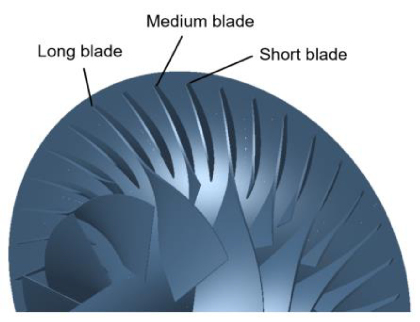
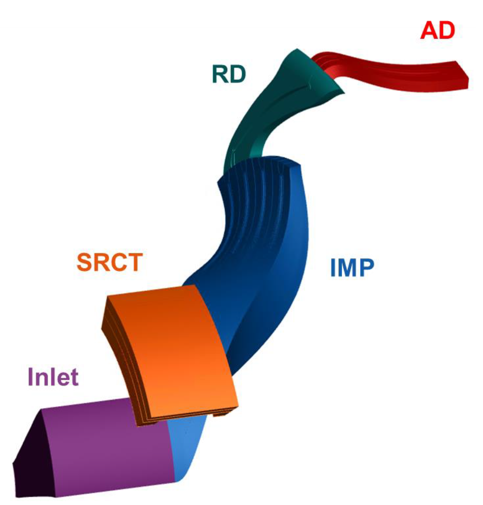
2.1. Case Description

The research object is an in-house designed single-stage centrifugal compressor with a pressure ratio equal to 12.0. The main components include the inlet, centrifugal impeller (IMP), SRCT, radial diffuser (RD), and axial diffuser (AD). Its total pressure ratio at the design point is 12.0. The centrifugal impeller has a multi-splitter configuration and includes three blade sets, named long blade, medium blade, and short blade. In the downstream of the impeller, vaned-type radial and axial diffusers are adopted to recover the pressure. The geometry of the centrifugal impeller is shown in Figure 1. The main design parameters and dimensions are listed in Table 1, and more detailed information regarding the compressor can be found in the literature [16].

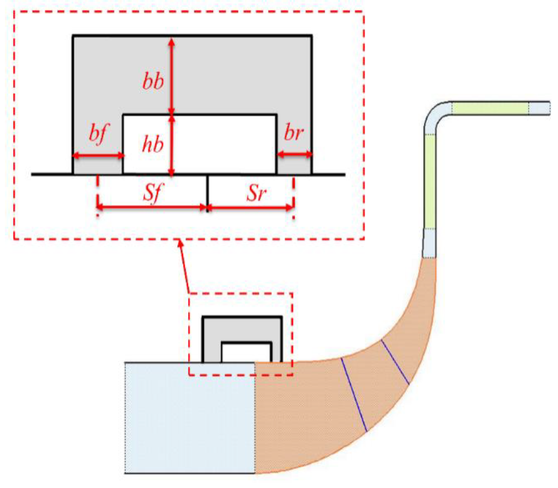
2.2. Parametric model of SRCT

In this work, the geometry of SRCT is characterized by six independent parameters, as shown in Table 2 and Figure 2. They are rear slot distance (Sr), rear slot width (Br), front slot distance (Sf), front slot width (Bf), channel height (Hb), and channel width (Bb). Previous studies [19,24] indicate that the rear slot distance and width are the most influential parameters affecting compressor aerodynamic stability. Therefore, this study will focus on these two parameters and keep the remaining four parameters fixed. The first value for Sr and Br in Table 2 is their reference value.

2.3. Numerical Methods

A numerical simulation is employed to evaluate the effect of SRCT on compressor performance and further explore the flow mechanisms behind it. The NUMECA fine/turbo solver is selected to conduct the simulations, which is based on a finite volume scheme to solve steady three-dimensional Reynolds-Averaged Navier Stokes (RANS) equations. The flow medium of air is set as the perfect gas, and the Spalart–Allmaras (SA) single equation model is chosen as the turbulence model.
The calculation domain of the compressor is shown in Figure 3. For the discretization of the calculation domain, the inlet domain adopts a H topology mesh. The impeller, radial, and axial diffuser domains adopt the O4H topology mesh. The mesh view of the impeller domain and meridional section is shown in Figure 4.
The governing equation in the inlet and impeller domain is solved in the rotating frame. For the radial and axial diffuser domain, the simulation is conducted in the stationary frame. A mixing-plane treatment is used at the interface between the impeller exit and radial diffuser inlet, the same as the one between the radial diffuser exit and axial diffuser inlet. The total condition (101,325 Pa and 288.15 K) and flow direction (axial direction) are defined in the inlet boundary. Static pressure is imposed at the outlet boundary condition. All the wall boundaries are set to be non-slip and adiabatic.
The performance in a wide range of operating conditions is obtained by changing the back pressure from the choke point with the rotating speed of the impeller fixed to be the designed one. The step size of the back pressure rise is set to be 1 kPa at the operating conditions near surge until the calculation cannot reach a convergence, and the last convergent operating point is regarded as the surge boundary.
As for the convergence judgement, the residual convergence criterion is set to be 1 × 10⁻⁶ or with a maximum iteration number of 10,000 steps. Moreover, the iteration histories of overall mass flow rate, pressure ratio, and efficiency is monitoring; one more convergence criterion is set to be that the amplitudes of the above overall performance indexes are no more than 1% of the average values.
The numerical simulation Is conducted In the High-Performance Computing (HPC) cluster of the Turbomachinery Laboratory at Tsinghua University. For detailed computer node configuration, a Genuin Intel CPU with 28 cores is adopted to conduct the simulation. Generally, around two hours are needed to obtain the convergent result corresponding to one operating condition.

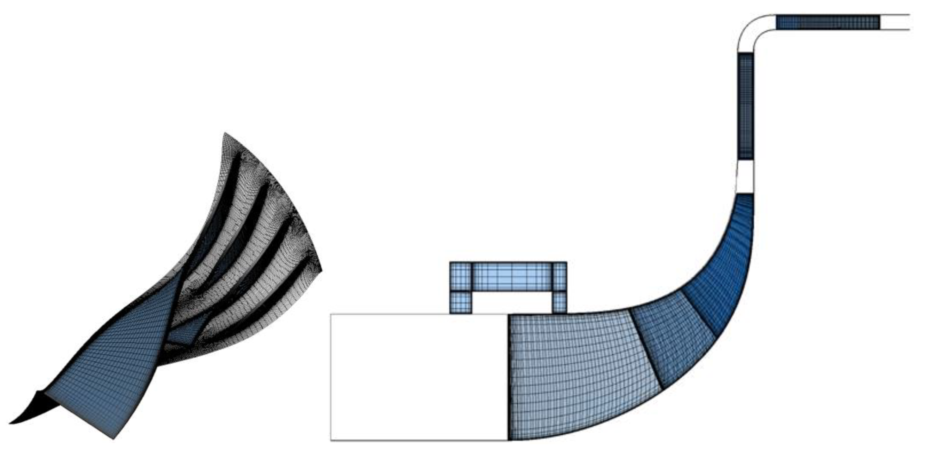
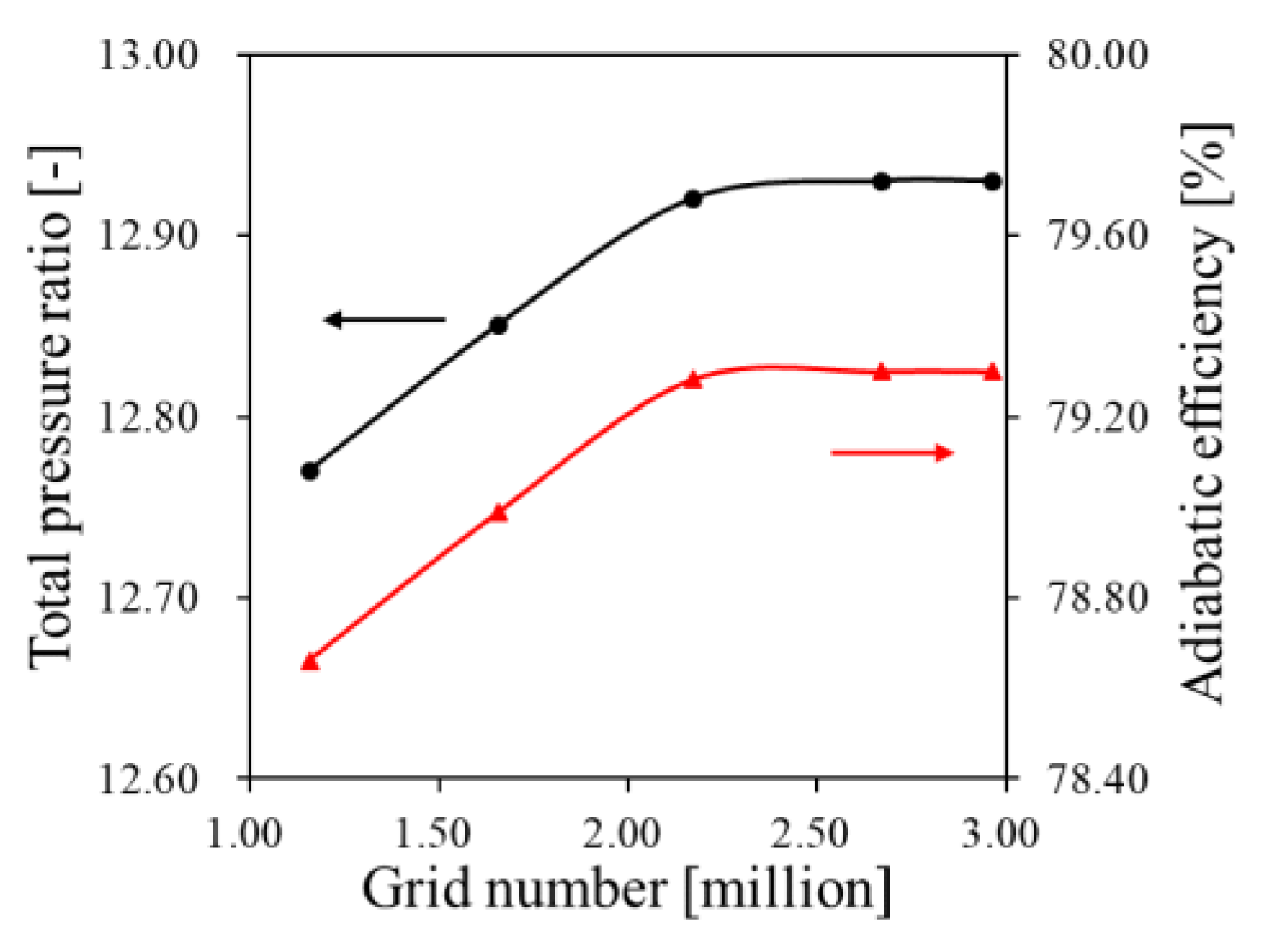
2.4. Mesh Independence Study

The mesh independence study is first conducted in this section. The cases with different mesh numbers along streamwise, pitchwise, and spanwise directions are calculated with the same settings for mesh topology, solver, turbulence model, and boundary condition. The result is presented in Figure 5. It can be concluded that when the total number of nodes reaches 2.2 million, the simulation results are independent of the mesh size. In this work, the mesh size for the entire impeller and vaned diffusers is chosen to be 2.9 million, which fulfills the mesh independence requirement.
For the detailed mesh setting, as shown in Figure 4, the streamwise mesh number in the impeller, radial diffuser, and axial diffuser is specified to be 87, 99, and 79, respectively, and the circumferential and spanwise mesh number for all the domains is set to be 43 and 53, respectively. The impeller tip clearance domain is discretized with 17 spanwise nodes.
The first layer thickness near the wall surface is 0.002 mm, with an expansion ratio equal to 1.337 along the normal direction. Moreover, it is also confirmed that the Y-plus value near the wall is lower than 3, which fulfills the requirement for the Spalart–Allmaras turbulent model.

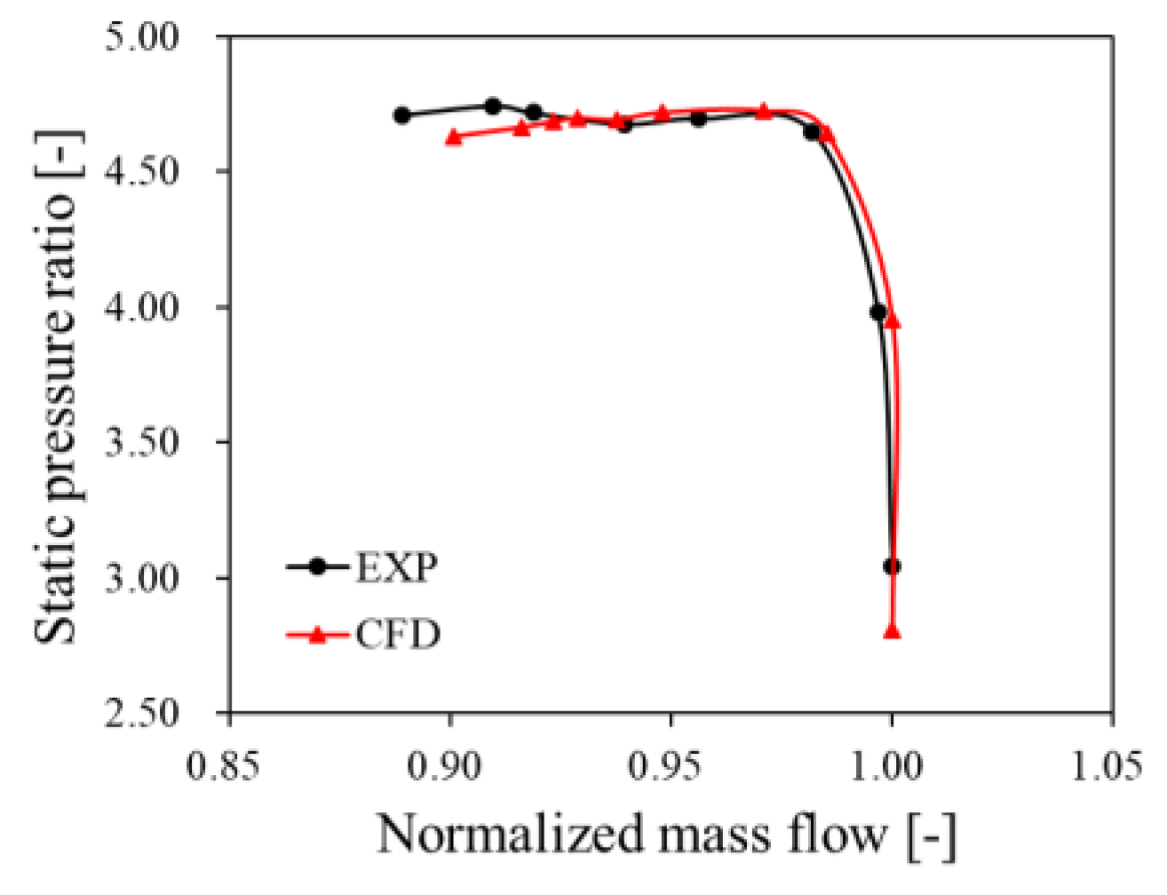
2.5. Numerical Method Validation

In order to validate the numerical methodology in the present work, an in-house designed centrifugal compressor named TTL-1 with available test results is employed. The comparison of compressor performance between the Experiment (EXP) and Computational Fluid Dynamics (CFD) simulation is presented in Figure 6; the static pressure ratio is the ratio between the impeller exit and impeller inlet, and the mass flow rate is normalized by the choke mass flow rate. It can be observed that the discrepancy in the static pressure ratio between the test and simulation is less than 2%, proving the good accuracy of the numerical method. As for further information regarding TTL-1, it can be found in the work of He et al. [19].

3. Results and Analysis

3.1. The Influence of SRCT on Performance

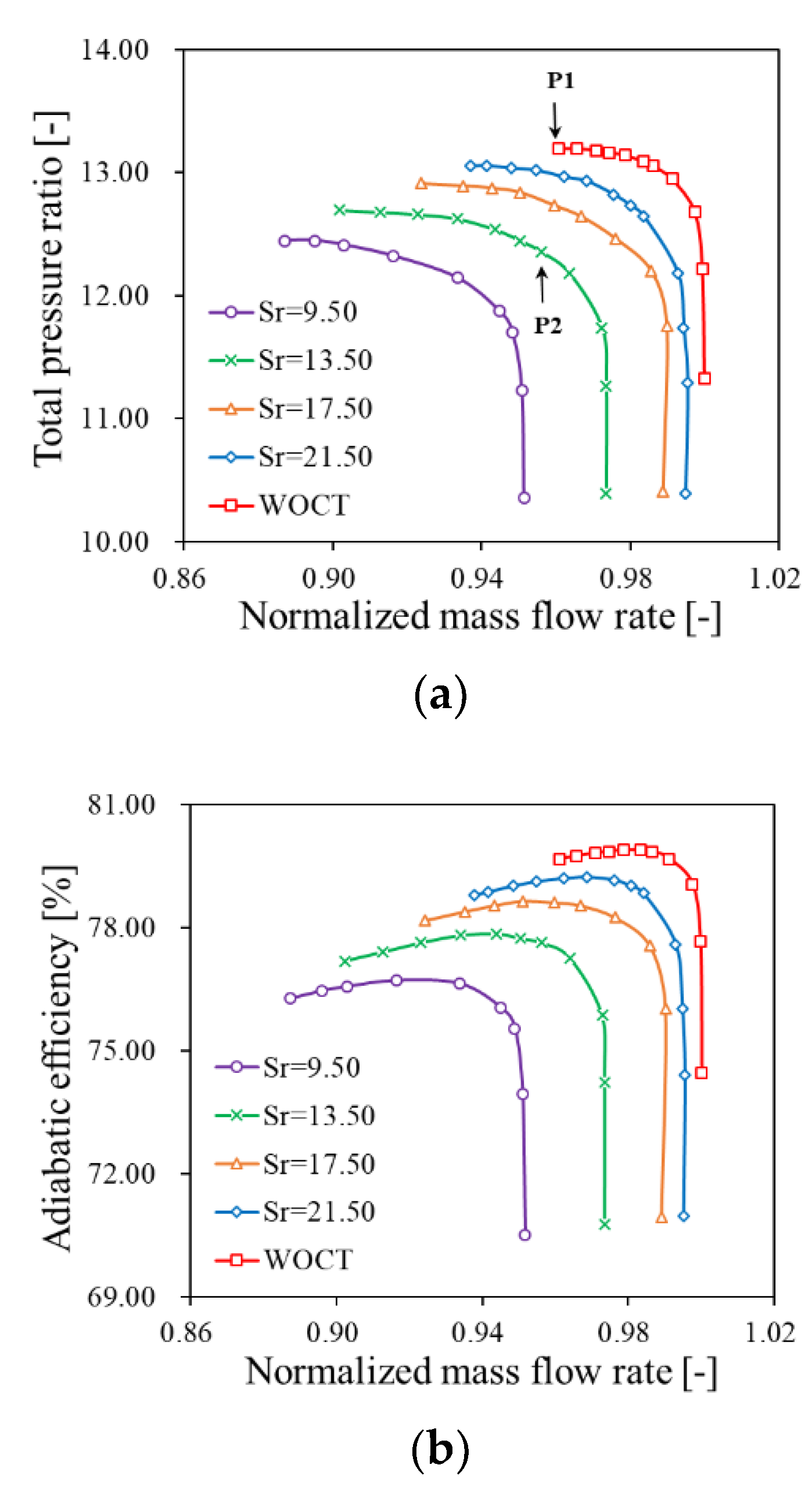
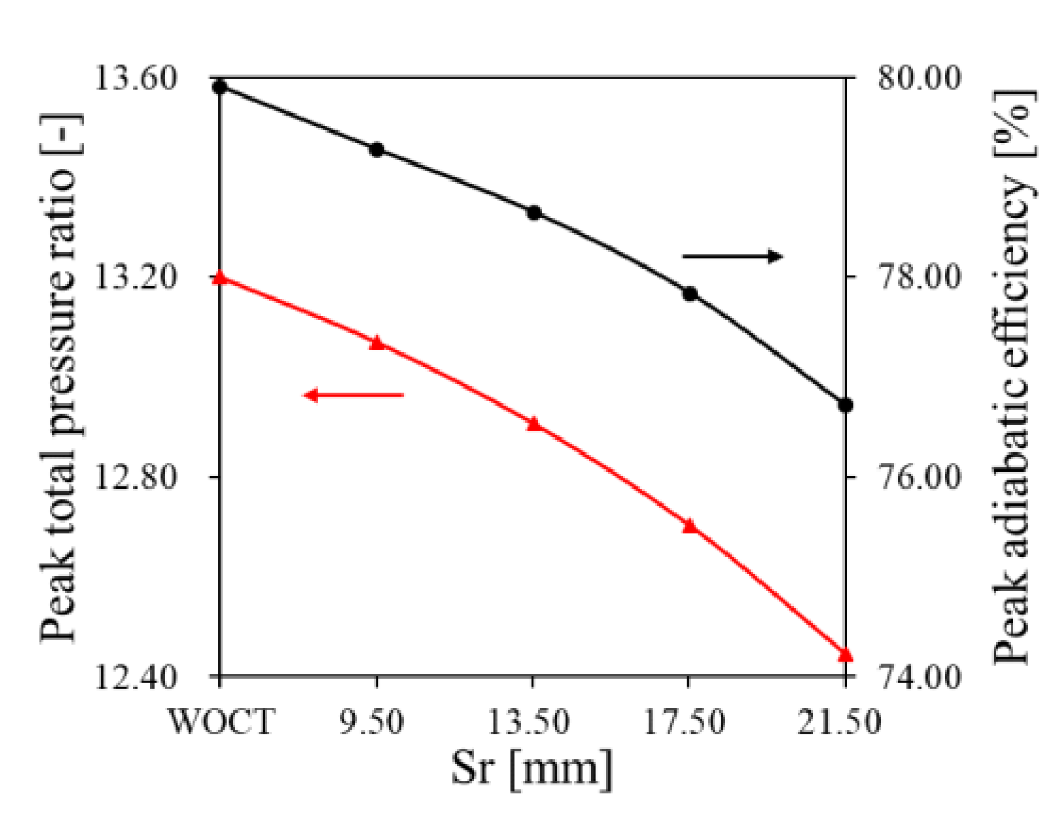
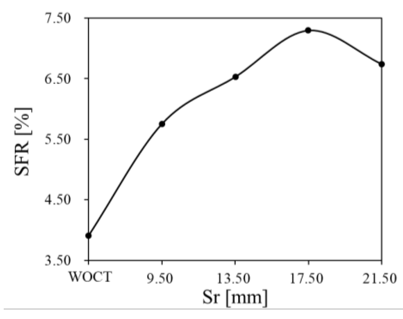
3.1.1. The Influence of Rear Slot Distance

Four different cases with altered Sr values are selected to reveal the influence of the rear slot distance on the performance of the compressor, while all the other parameters are fixed at the reference values listed in Table 2. The performance characteristics of compressors with different Sr values are shown in Figure 7, where “WOCT” represents the one without SRCT. It can be observed that, compared with the WOCT case, the performance of compressors with SRCT, including peak pressure ratio, peak efficiency, and chock mass flow, deteriorated gradually with the increase in Sr. The quantitative variation in peak pressure ratio and peak efficiency is shown in Figure 8. In Figure 8, the peak pressure ratio for the compressor without SRCT is 13.2. If Sr has a maximum value equal to 21.5 mm, the compressor will have the lowest peak pressure ratio equal to 12.5. The variation in efficiency with altered Sr has a similar trend to that of the pressure ratio. The peak efficiency of the compressor without SRCT is 79.9%, and the lowest peak efficiency is 76.7% for the compressor with SRCT when the Sr is specified to be 21.5 mm.
With the increase in Sr, the compressor performance curve will shift towards the left-bottom with the decrement in pressure ratio and choke flow rate. In order to quantitively evaluate the compressor instability by introducing the SRCT, the SFR is employed as defined in Equation (1).
SFR = ( 1 m surge m choke ) × 100 %
where m c h o k e and m s u r g e are the mass flow rate at the choke and near surge point, respectively.
Figure 9 shows the variation in SFR against Sr. From Figure 9, the non-linear and non-monotone relation between the SFR and Sr value can be observed. The SFR of the compressor without SRCT is 3.9% and is significantly broadened by introducing SRCT. The case with Sr equal to 17.5 mm is 7.3%, which reaches the maximum among all the investigated cases. However, the SRCT decreased the corresponding peak pressure ratio and peak efficiency by 2.1% and 3.8%, respectively.

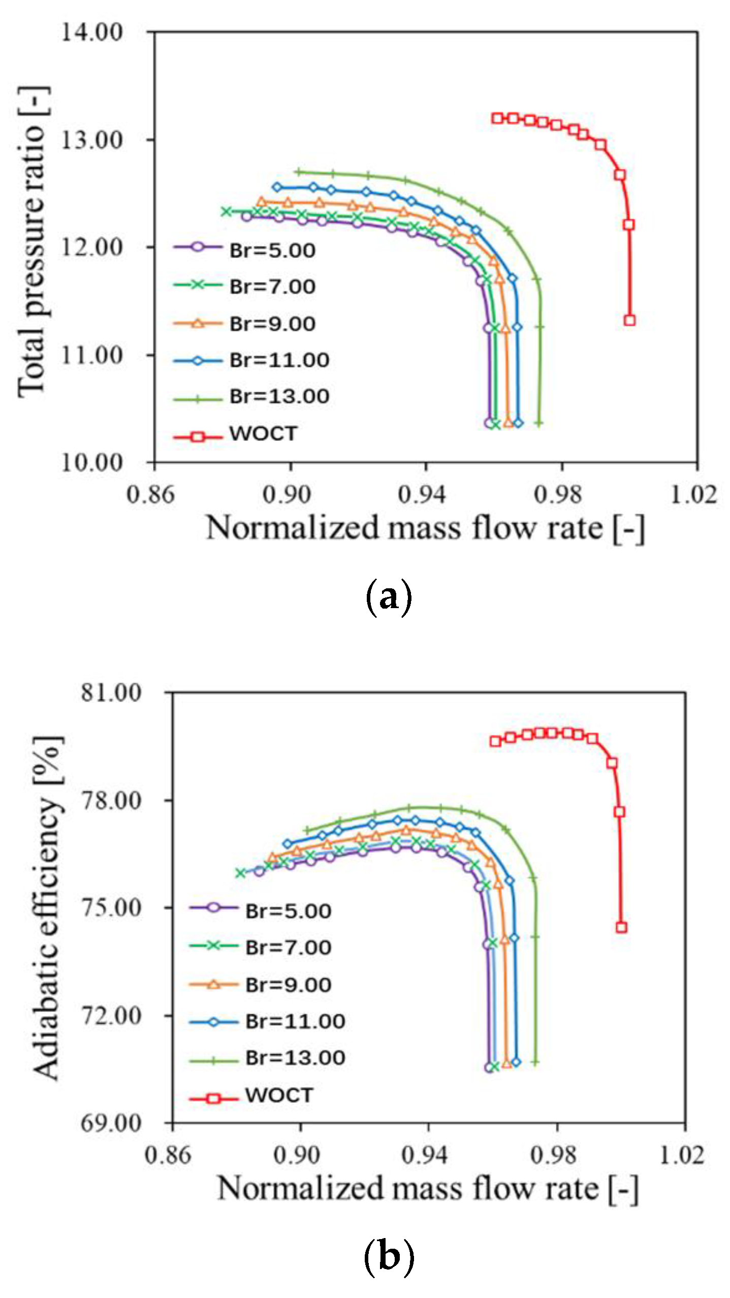
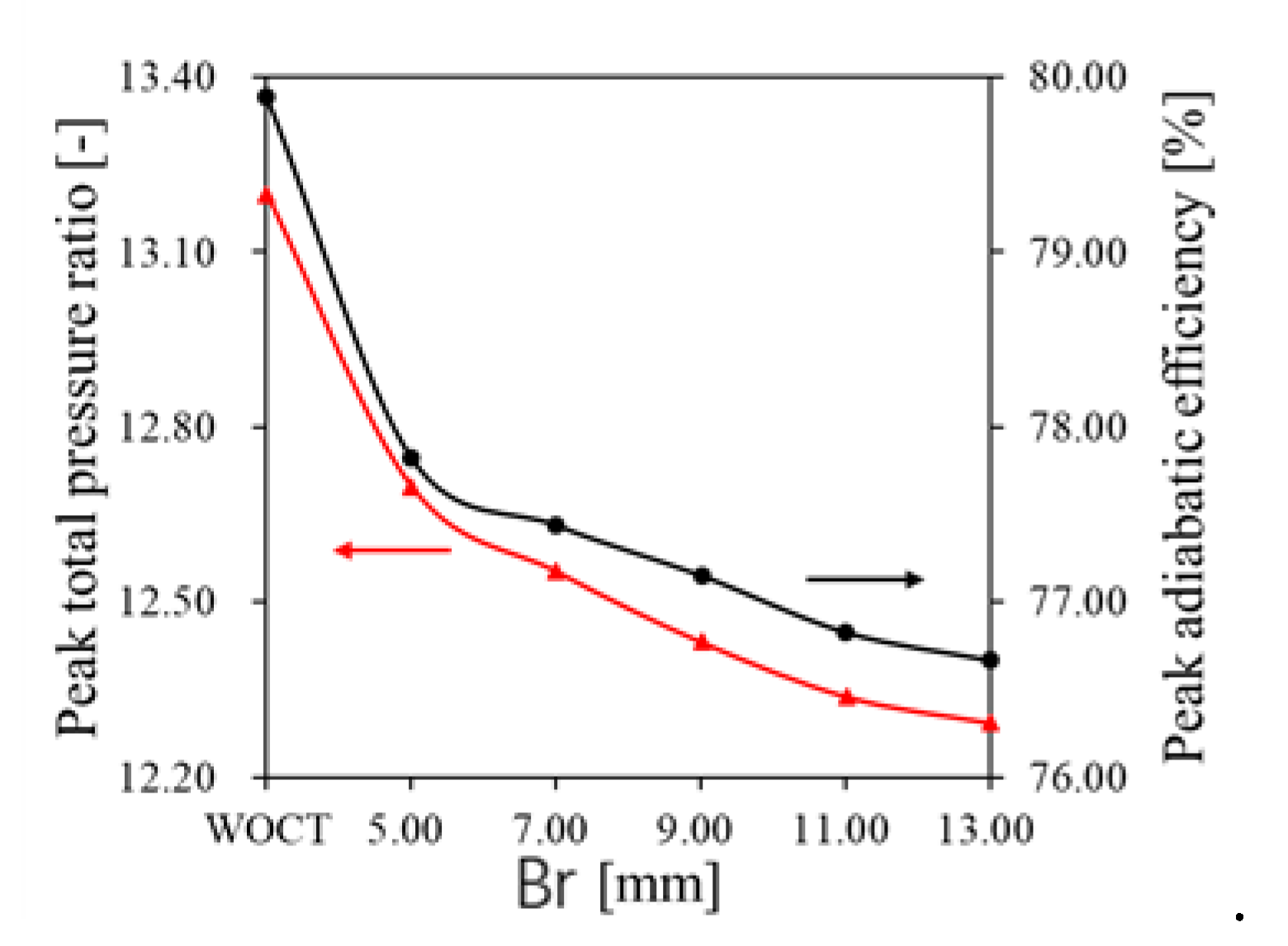
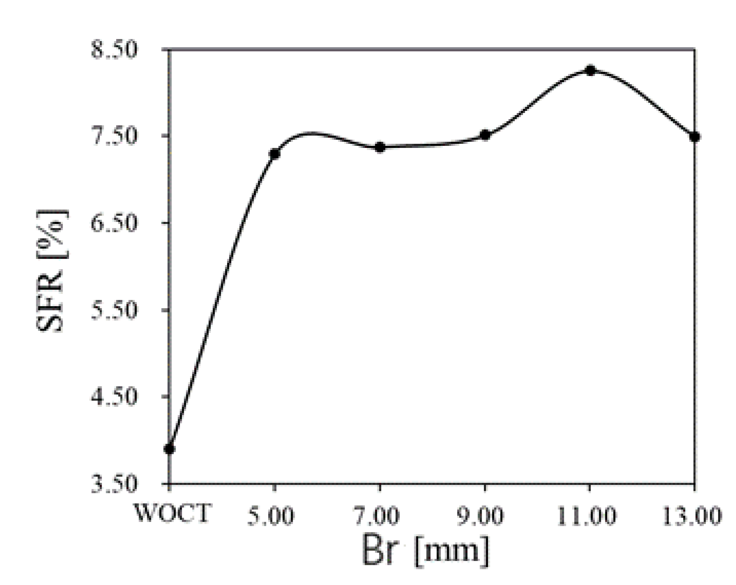
3.1.2. The Influence of Rear Slot Width

Five different cases with changed Br are selected to explore the influence of the rear slot width on the performance of the compressor, while all the other parameters are fixed at the reference values in Table 2. The characteristics of compressors with respect to different Br values are shown in Figure 10. Compared with the WOCT case, the performance of compressors with SRCT deteriorated gradually as the value of Br increased. The variation in peak pressure ratio and peak efficiency against Br is shown in Figure 11. It shows that the case with the maximum value of Br has the lowest peak pressure ratio, 12.3, and peak efficiency, 76.7%.
The variation in SFR with changed Br values is presented in Figure 12. It is indicated that a clear non-linear relationship exists between the SFR and Br value. When the Br is firstly increased to 5 mm, a clear enhancement of SFR can be observed. However, the continuous increase in the Br from 5mm has a subtle effect on the SFR. Among all the cases, it can be found that the case with Br equal to 11 mm has the best SFR, whose value is 8.3%. However, compared to the case of WOCT, its peak pressure ratio and peak efficiency decreased by 6.5% and 3.1%, respectively.

3.2. The Flow Mechanism for the Influence of SRCT

Based on the previous section, the SRCT has trade-off effects on the performance of the compressor, broadening the SFR and deteriorating performance at the stable operation conditions. In this section, the detailed change in flow structure induced by SRCT is carefully investigated, and the case with the Sr and Br of SRCT equal to 17.50 mm and 5.00 mm is chosen to be the object.

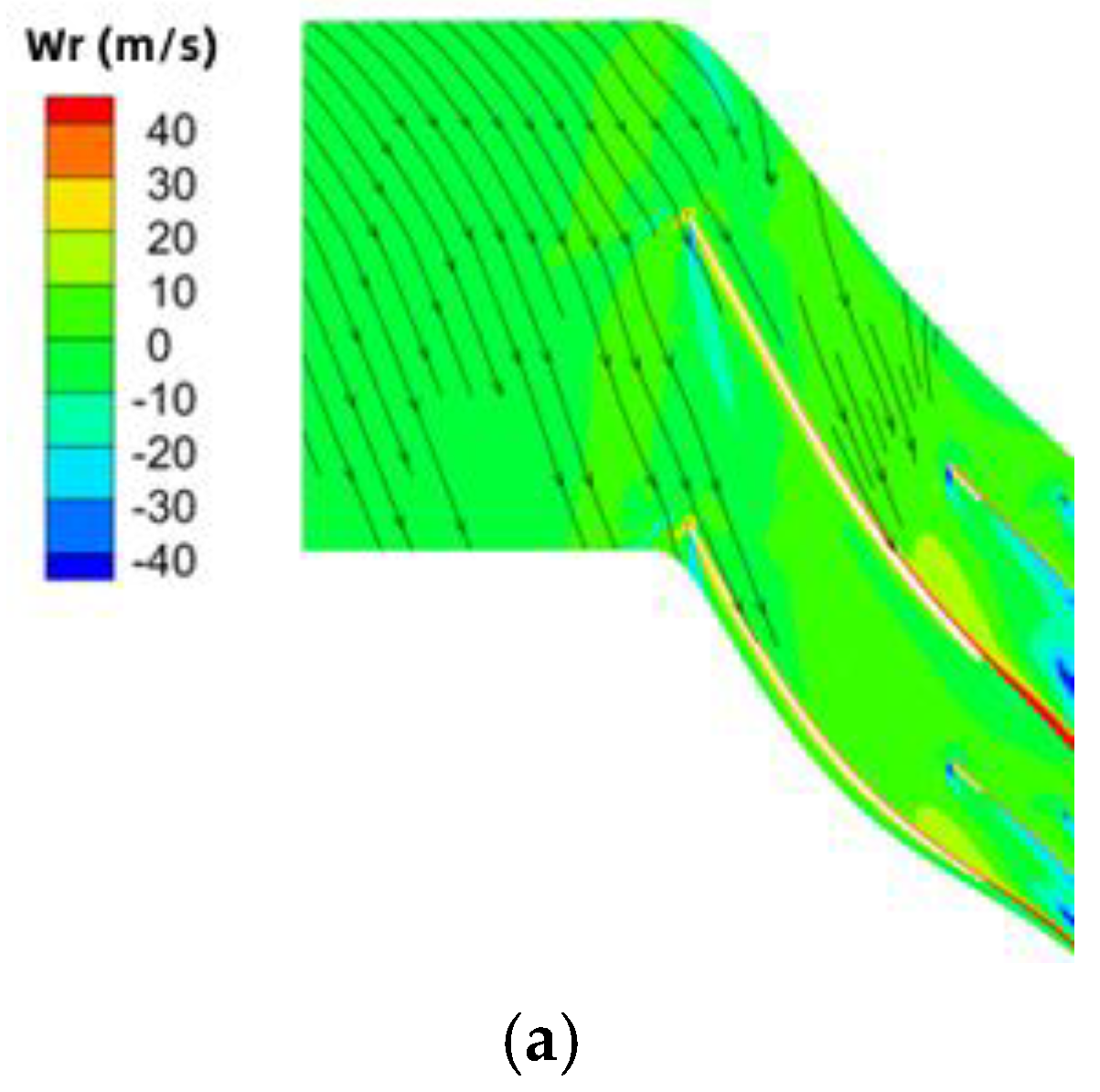
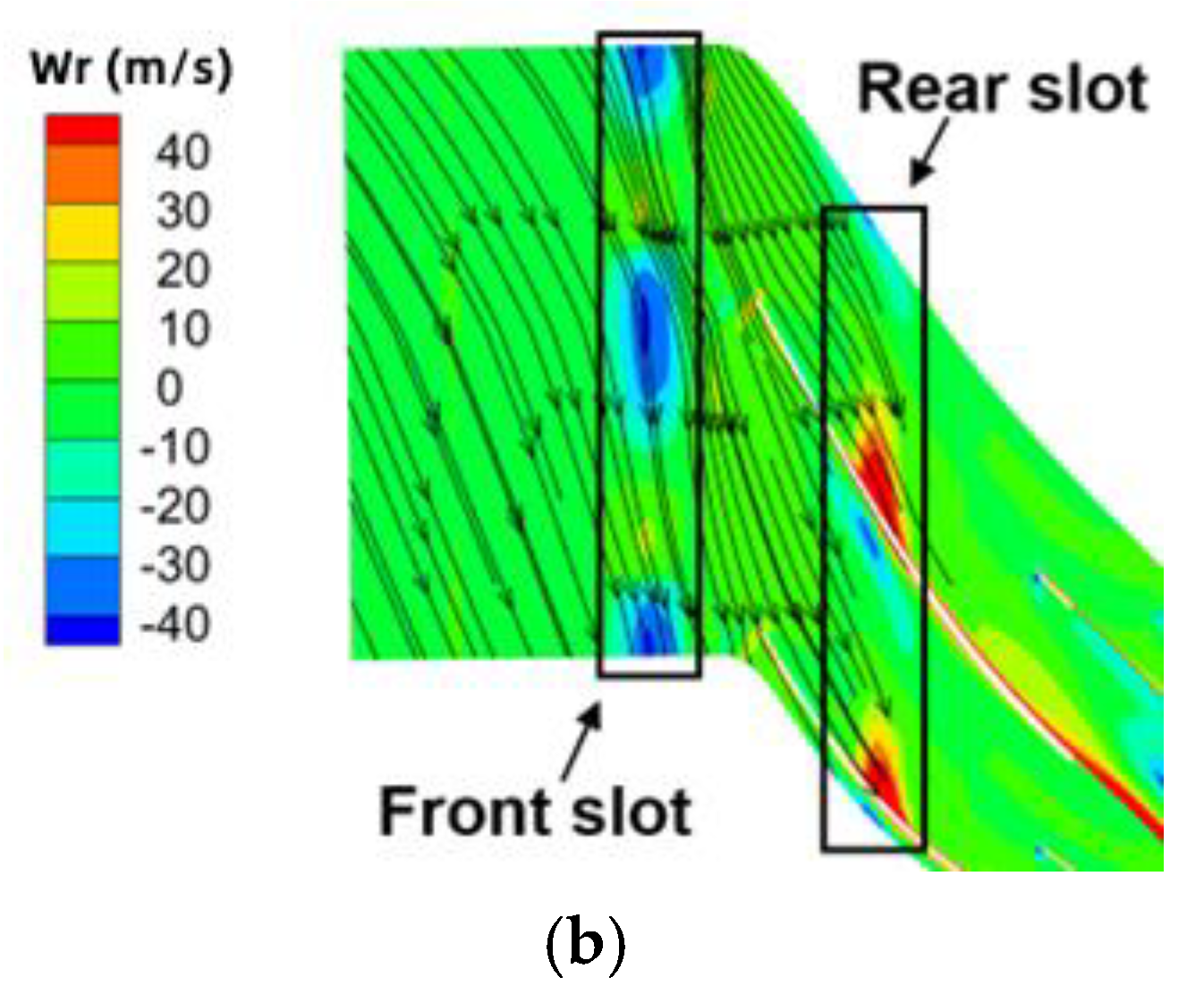
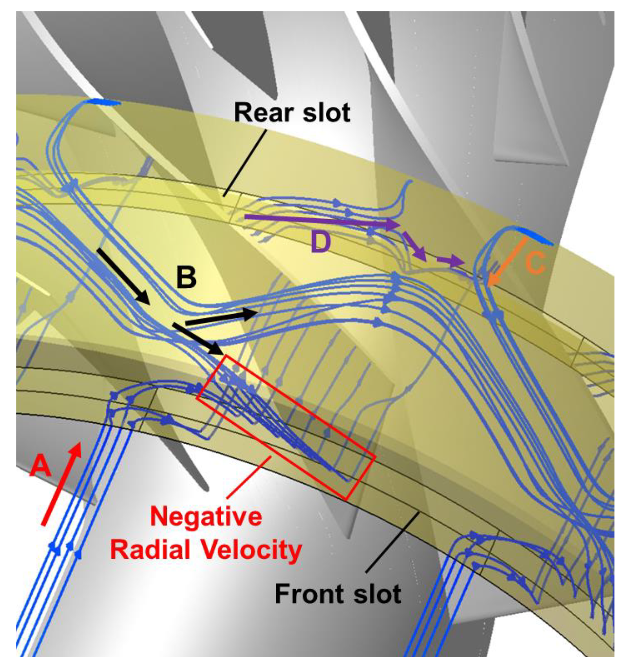
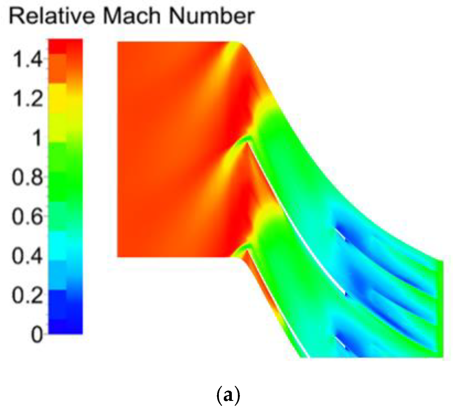
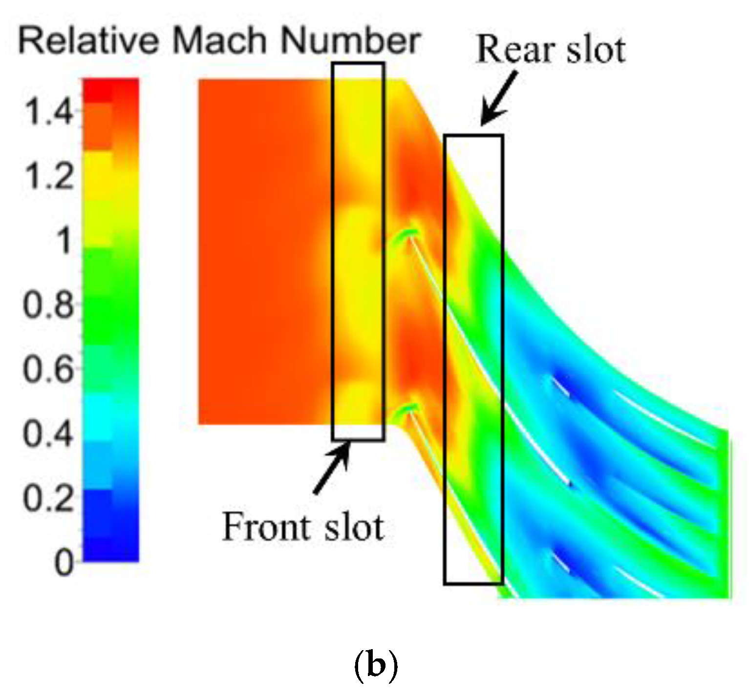
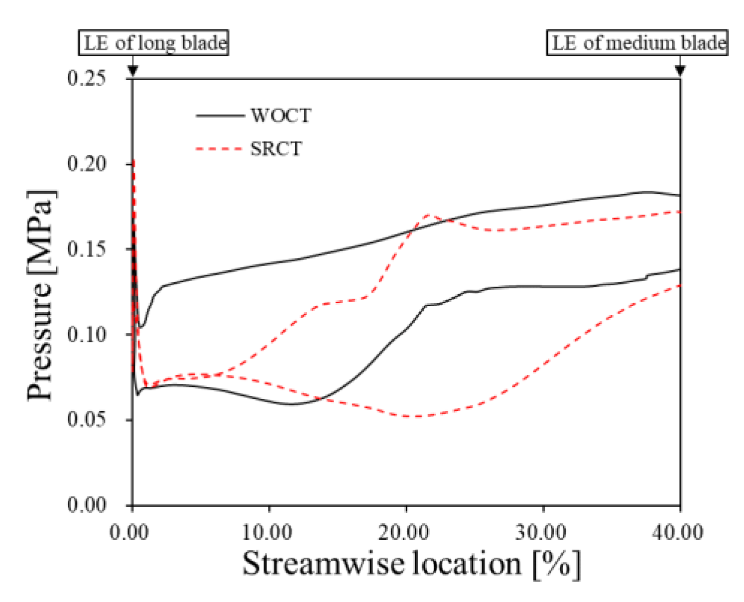
3.2.1. The Effect of SRCT on the Flow Behavior at the Impeller

The distribution of the radial velocity component and flow streamline in the 99% spanwise section is presented in Figure 13, where the black line shows the front and rear positions of the SRCT. The compressor without SRCT is operating at the near surge point P1, as shown in Figure 7a, and the compressor with SRCT is operating at point P2 with the same mass flow rate as P1. The operating points analyzed in the following sections stay unchanged unless otherwise specified.
From Figure 13, it can be observed that SRCT clearly changes the radial velocity distribution of the flow field near the impeller inlet and upstream of the medium blade. For the compressor without SRCT, there is an apparent negative radial velocity region existing near the suction surface of the long blade LE, caused by the leakage flow. For the compressor with SRCT, the negative radial velocity region is almost eliminated at the corresponding position. However, two regions with negative radial velocity exist near the streamwise locations of both slots. Also, accompanying the region with negative radial velocity near the rear slot, an apparent region with positive radial velocity exists near the pressure surface of the long blade. Moreover, it can also be observed that the streamline direction shifted after passing through the blue and red color regions, representing the aspirated and injected flow from SRCT mixing with the main flow in the impeller flow passage.
To further understand the change in flow behavior by introducing the SRCT, Figure 14 is portrayed to show the flow streamline in the slots of SRCT, and four distinct flow features can be identified. In the front slot, the upcoming flow A enters the cavity and is redirected by the interaction with the flow B, which features the recirculation flow from the rear slots with a strong swirl along the rotating direction. Eventually, both flows leave the slot and mix with the mainstream to form the negative radial velocity region near the front slot shown in Figure 13. A similar flow feature can also be found in the rear slot, which is labeled as flow D to feature the flow originating from the pressure surface of the long blade along the circumferential direction in the rear slot. In addition, the leakage flow (flow C) from the pressure surface to the suction surface emerges above the long blade, whose flow direction is opposite to flow D along the counter-rotating direction. Both flow C and flow D originate from pressure surface mixed with the mainstream flow, resulting in a positive radial velocity region near the pressure surface and a negative radial velocity region near the suction surface.
The distribution of static pressure and relative Mach number in the 99% spanwise section is shown in Figure 15 and Figure 16, respectively. It can be observed that for the compressor without SRCT, a detached shock wave originating near the LE of the blade extends to the adjacent blade, resulting in a significant pressure difference between the pressure side and suction side, as well as a high blade loading near the impeller LE. On the other hand, in the case of SRCT, the blade loading is significantly alleviated with a reduced pressure difference between pressure and suction surface near the long blade LE. The reason for this is that the fluid at the front slot mixes with the mainstream and decreases the inlet Mach number at the impeller inlet, which almost eliminates the detached shock wave and moves the position of the shock wave downstream into the flow passage. Therefore, the change in shock wave position reduces the pressure difference and suppresses the leakage flow near long blade LE. Moreover, with the downstream movement of the shock wave, the pressure difference across the blade and blade loading is clearly increased near the rear slot, which is considered to be the reason for flow C and flow D in Figure 13.
Figure 17 shows the distribution of pressure in the 99% spanwise section around the blade surface, from LE to 40% chord of the long blade. For the compressor without SRCT, the pressure at the pressure side increases sharply due to the detached shock wave, resulting in high blade loading near blade LE, which generates leakage flow originating from the pressure side near LE. When SRCT is introduced, the high blade loading near the LE is eliminated due to the recirculation flow mix and decrease in inlet relative Mach number. In contrast, with the downstream movement of the shock wave, the sharp pressure increase at the pressure side can be observed in the 21% streamwise location, and the pressure difference reaches a peak value at nearly the same location, resulting in high blade loading.
Generally, in an ultra-high-pressure-ratio centrifugal compressor, the inlet Mach number is higher than in a conventional design due to the high rotating speed needed to reach an enhanced design pressure ratio. Therefore, the shock wave and blade loading near the LE are extremely high to induce the clear leakage flow. Therefore, more attention needs to be paid to the shock wave weakening and blade loading alleviating effect by introducing the SRCT while designing an ultra-high-pressure ratio centrifugal compressor.
To summarize the SRCT’s effect on the flow behavior, the introduction of SRCT provides an additional flow path across the blade along the circumferential direction. Due to the flow features in the slots, the behavior of the shock wave and tip leakage flow is significantly changed, resulting in the obviously changed loading distribution along the streamwise direction.

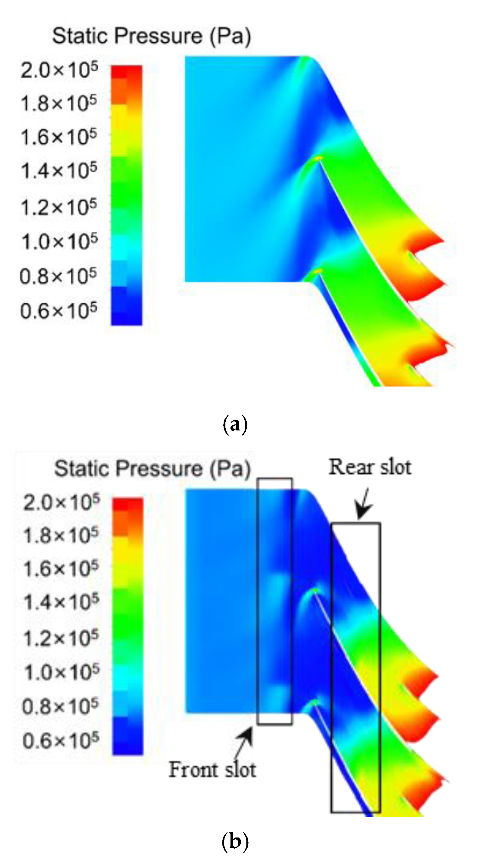
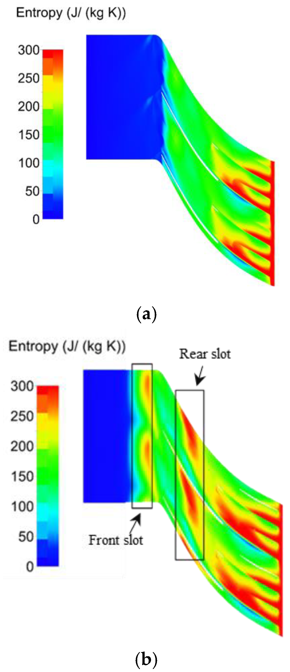
3.2.2. The Effect of SRCT on Aerodynamic Performance

This section concentrates on the analysis of flow mechanisms behind the aerodynamic performance change by introducing the SRCT. Firstly, the contour of entropy in the 99% spanwise section is shown in Figure 18. For the case without SRCT, the entropy increase mainly appears in the impeller flow passage near the rear slot caused by the flow separation induced by the strong flow diffusion [25], as in the low momentum region shown in Figure 16a. In addition, the leakage flow emerging at the LE of the middle blade interacts with the mainstream flow, decreasing the momentum of flow and thus exacerbating the flow loss.
As shown in Figure 18b, compared with the entropy distribution in the case of WOCT, an obvious entropy increase can be found in the regions near both the front and rear slots with a negative radial velocity, shown in Figure 13b. The main reason for this could be that the recirculation flow with low momentum mixes with the mainstream near the slots. Moreover, it can also be observed that the high entropy region in the impeller flow passage near the rear slot clearly enlarges when SRCT is introduced. As mentioned in the previous section, the blade loading distribution along the streamwise direction is changed by introducing the SRCT with the shock wave moving toward downstream. Therefore, the adverse pressure gradient is enhanced in the impeller flow passage near the rear slot. As a result, the flow separation loss and entropy increase are enhanced. Owing to the three regions with high flow loss and entropy increase mentioned above, the efficiency of the compressor with SRCT drops, as shown in Figure 7 and Figure 10.
The mixing of recirculation and mainstream flow will not only introduce loss but also increase the flow blockage caused by the low momentum fluid near the impeller LE. Figure 19 plots the spanwise distribution of axial velocity and incidence near the impeller inlet. It can be observed that the mixing of recirculation and mainstream flow reduces the axial velocity and increases the incidence angle above the 90% spanwise section. However, the axial velocity below the 90% spanwise section is clearly increased, resulting in a decrease in the incidence due to the flow area blockage effect. This effect will greatly stabilize the flow field in most of the span range, enhancing the stability of the impeller flow, as shown in Figure 7 and Figure 10. Especially for an ultra-high-pressure-ratio centrifugal compressor, the stability issue related to the inlet incidence angle is amplified due to the large inlet relative circumferential velocity due to the high rotating speed. Therefore, the stabilization effect by improving the incidence angle near the tip region by introducing the SRCT plays a more important role in enhancing the SFR of the compressor.

4. Conclusions

In this work, three-dimensional flow simulation is applied to the parametric geometry model to investigate the effect of SRCT on the performance of an ultra-high-pressure-ratio centrifugal compressor, and the detailed flow structure is compared between the operations with and without SRCT. The flow mechanisms behind the influence of SRCT on aerodynamic performance are explored. Several conclusions are drawn as follows:
1. The SRCT has trade-off effects on the compressor performance, including the extension of SFR and the deterioration of efficiency. The efficiency gradually worsens with the increase in rear slot distance or rear slot width. In contrast, a non-linear and non-monotone relationship exists between the SFR and rear slot distance or width, and the stability enhancement effect will be weakened when the rear slot distance or width is increased to a certain value.
2. The introduction of SRCT provides an additional flow path across the blade along the circumferential direction. Due to the flow features in the slots, the behavior of the shock wave and tip leakage flow is significantly changed, resulting in the obviously different loading distribution along the streamwise direction. This flow behavior change by introducing SRCT needs more attention, especially for an ultra-high-pressure-ratio centrifugal compressor design with a clearly strong shock wave and tip leakage flow due to a high inlet Mach number and blade loading.
3. The flow in both the front and rear slots of SRCT mixes with the mainstream near the blade tip, causing a flow loss increase. Moreover, the movement of the shock wave and change in the streamwise blade loading distribution caused by introducing SRCT increase the loss in the impeller flow passage near the rear slot, which further deteriorates the efficiency.
4. The blockage effect caused by the mixing of recirculation and mainstream flow near the impeller inlet increases the axial velocity and reduces the incidence angle below the 90% spanwise section. This effect clearly stabilizes the flow field in most of the span range and enhances the stability of the impeller flow. The stabilization effect plays an even more important role in an ultra-high-pressure-ratio centrifugal compressor design with a more critical issue due to the incidence near the tip region.

Author Contributions

Conceptualization, B.W.; methodology, T.F.; software, T.F.; validation, C.Y.; formal analysis, Z.S.; investigation, W.Z.; resources, B.W.; data curation, T.F.; writing—original draft preparation, T.F.; writing—review and editing, B.W.; visualization, C.Y.; supervision, B.W.; project administration, X.Z.; funding acquisition, X.Z. All authors have read and agreed to the published version of the manuscript.

Funding

The authors would like to acknowledge the support from the National Science and Technology Major Project (2017-II-0002-0014).

Data Availability Statement

Not applicable.

Conflicts of Interest

The authors declare no conflict of interest.

Abbreviations

Notation
SRCTSelf-Recirculating Casing Treatment
WOCTWithout Self-Recirculating Casing Treatment
RANSReynolds-Averaged Navier Stokes
HPCHigh-Performance Computing
SASpalart–Allmaras
IMPImpeller
RDRadial diffuser
ADAxial diffuser
SFRStable Flow Range
LELeading Edge
TETrailing Edge
WVelocity
Subscripts
chokeChoke point
surgeNear surge point
rRadial direction

References

  1. Hung, K.-S.; Ho, K.-Y.; Hsiao, W.-C.; Kuan, Y.-D. The Characteristic of High-Speed Centrifugal Refrigeration Compressor with Different Refrigerants via CFD Simulation. Processes 2022, 10, 928. [Google Scholar] [CrossRef]
  2. Wei, Y.; Li, B.; Xu, X.; Wei, M.; Wang, C. Design of Electric Supercharger Compressor and Its Performance Optimization. Processes 2023, 11, 2132. [Google Scholar] [CrossRef]
  3. Palmer, D.L.; Waterman, W.F. Design and Development of an Advanced Two-Stage Centrifugal Compressor. J. Turbomach. 1995, 117, 205. [Google Scholar] [CrossRef]
  4. Kim, J.; Lee, E.; Yang, S. A Numerical Investigation on the Centrifugal Compressor Stage for a Small Turboshaft Engine. In Proceedings of the ASME/JSME 2003 4th Joint Fluids Summer Engineering Conference, Volume 2: Symposia, Parts A, B, and C, Honolulu, HI, USA, 6–10 July 2003; pp. 707–712. [Google Scholar]
  5. Krain, H.; Hoffman, W. Verification of an impeller design by laser measurements and 3D-viscous flow calculations. In Proceedings of the ASME 1989 International Gas Turbine and Aeroengine Congress and Exposition, Volume 1: Turbomachinery, Toronto, ON, Canada, 4–8 June 1989; V001T01A064. [Google Scholar]
  6. Higashimori, H.; Hasagawa, K.; Sumida, K.; Suita, T. Detailed flow study of mach number 1.6 high transonic flow with a shock wave in a pressure ratio 11 centrifugal compressor impeller. J. Turbomach. 2004, 126, 473. [Google Scholar] [CrossRef]
  7. Higashimori, H.; Morishita, S.; Suzuki, M.; Suita, T. Detailed flow study of mach number 1.6 high transonic flow in a pressure ratio 11 centrifugal compressor impeller: Part 2-Effect of the inducer shroud bleed and development of a low energy region along the shroud. In Proceedings of the ASME Turbo Expo 2007: Power for Land, Sea, and Air, Volume 6: Turbo Expo 2007, Parts A and B, Montreal, QC, Canada, 14–17 May 2007; pp. 1071–1080. [Google Scholar]
  8. Kang, S. Numerical Investigation of a High Speed Centrifugal Compressor Impeller. In Proceedings of the ASME Turbo Expo 2005: Power for Land, Sea, and Air, Volume 6: Turbo Expo 2005, Parts A and B, Reno, NV, USA, 6–9 June 2005; pp. 813–821. [Google Scholar]
  9. Ibaraki, S.; Matsuo, T.; Kuma, H.; Sumida, K.; Suita, T. Aerodynamics of a transonic centrifugal compressor impeller. J. Turbomach. 2003, 125, 346. [Google Scholar] [CrossRef]
  10. Ibaraki, S.; Furukawa, M.; Iwakiri, K.; Takahashi, K. Vortical Flow Structure and Loss Generation Process in a Transonic Centrifugal Compressor Impeller. In Proceedings of the ASME Turbo Expo 2007: Power for Land, Sea, and Air, Volume 6: Turbo Expo 2007, Parts A and B, Montreal, QC, Canada, 14–17 May 2007; pp. 1089–1098. [Google Scholar]
  11. Oana, M.; Kawamoto, O.; Ohtani, H.; Yamamoto, Y. Approach to high performance transonic centrifugal compressor. J. Propul. Power. 2004, 20, 602. [Google Scholar] [CrossRef]
  12. Japikse, D. Centrifugal Compressor Design and Performance; Wilder: Windsor County, VT, USA, 1996. [Google Scholar]
  13. Zhang, Q.; Zhang, L.; Huo, Q.; Zhang, L. Study on Two Types of Stall Patterns in a Centrifugal Compressor with a Wide Vaneless Diffuser. Processes 2020, 8, 1251. [Google Scholar] [CrossRef]
  14. Traficante, S.; De Giorgi, M.G.; Ficarella, A. Flow Separation Control on a Compressor-Stator Cascade Using Plasma Actuators and Synthetic and Continuous Jets. J. Aerosp. Eng. 2016, 29, 04015056. [Google Scholar] [CrossRef]
  15. Li, L.; Song, Y.; Chen, F. Flow Control on Bowed Compressor Cascades Using Vortex Generator Jet at Different Incidences. J. Aerosp. Eng. 2017, 30, 04017028. [Google Scholar] [CrossRef]
  16. Zhang, W.; He, X.; Wang, B.; Sun, Z.; Zheng, X. Stability Improvement of a High-Pressure Ratio Centrifugal Compressor by Flow Injection. J. Aerosp. Eng. 2020, 33, 04020072. [Google Scholar] [CrossRef]
  17. Sun, X.; Dong, X.; Sun, D. Recent development of casing treatments for aero-engine compressors. Chin. J. Aeronaut. 2019, 32, 1. [Google Scholar] [CrossRef]
  18. Liang, Y.; Song, W.; Chen, H.; Zhang, Y. Numerical Investigation of Premature Stall in a Non-Tip-Loaded Rotor Caused by Circumferential Groove Casing Treatment. J. Aerosp. Eng. 2021, 34, 04021032. [Google Scholar] [CrossRef]
  19. Tamaki, H. Effect of recirculation device on performance of high pressure ratio centrifugal compressor. J. Turbomach. 2010, 134, 1879. [Google Scholar]
  20. He, X.; Zheng, X. Roles and Mechanisms of Casing Treatment on Different Scales of Flow Instability in High Pressure Ratio Centrifugal Compressors. Aerosp. Sci. Technol. 2019, 84, 734. [Google Scholar] [CrossRef]
  21. Gancedo, M.; Gutmark, E.; Guillou, E. PIV measurements of the flow at the inlet of a turbocharger centrifugal compressor with recirculation casing treatment near the inducer. Exp. Fluids 2016, 57, 16. [Google Scholar] [CrossRef]
  22. Yang, M.; Martines-botas, R.; Deng, K.; Zhang, Y.; Zheng, X. Unsteady influence of Self Recirculation Casing Treatment (SRCT) on high pressure ratio centrifugal compressor. Int. J. Heat Fluid Flow 2016, 58, 19. [Google Scholar]
  23. Yang, M.; Martinez-botas, R.; Zhang, Y.; Zheng, X. Effect of Self-Recirculation-Casing Treatment on High Pressure Ratio Centrifugal Compressor. J. Propul. Power 2016, 32, 602–610. [Google Scholar] [CrossRef]
  24. Hu, L.; Sun, H.; Yi, J.; Curtis, E.; Zhang, J.; Yang, C.; Krivitziky, E. Numerical and experimental investigation of a compressor with active self-recirculation casing treatment for a wide operation range. Proc. Inst. Mech. Eng. Part D J. Automot. Eng. 2013, 227, 1227. [Google Scholar] [CrossRef]
  25. Zhang, W.; Sun, Z.; Wang, B.; Zheng, X. Influence of splitter blades on the performance of a single stage centrifugal compressor with pressure ratio 12.0. In Proceedings of the ASME Turbo Expo 2020: Turbomachinery Technical Conference and Exposition, Volume 2E: Turbomachinery, Virtual, Online, 21–25 September 2020. V02ET39A016. [Google Scholar]
Figure 1. Centrifugal compressor with multi-splitter configuration.
Processes 11 02439 g001
Figure 2. Parametric definition of SRCT.
Processes 11 02439 g002
Figure 3. Calculation domain of the compressor.
Processes 11 02439 g003
Figure 4. Mesh view of the impeller domain and meridional section.
Processes 11 02439 g004
Figure 5. The validation of mesh independence.
Processes 11 02439 g005
Figure 6. The comparison of experimental and simulation results for compressor TTL-1.
Processes 11 02439 g006
Figure 7. The characteristics of compressors with different Sr ((a) total pressure ratio characteristic, (b) adiabatic efficiency).
Processes 11 02439 g007
Figure 8. The variation in peak pressure ratio and peak efficiency against Sr.
Processes 11 02439 g008
Figure 9. The variation in SFR against Sr.
Processes 11 02439 g009
Figure 10. The characteristics of compressors with different Br ((a) total pressure ratio characteristic, (b) adiabatic efficiency).
Processes 11 02439 g010
Figure 11. The variation in peak pressure ratio and peak efficiency against Br.
Processes 11 02439 g011
Figure 12. The variation in SFR against Br.
Processes 11 02439 g012
Figure 13. Distribution of radial velocity and flow streamline in the 99% spanwise section of the blade ((a) operation without SRCT, (b) operation with SRCT).
Processes 11 02439 g013aProcesses 11 02439 g013b
Figure 14. Distribution of streamlines at SRCT and impeller flow passage.
Processes 11 02439 g014
Figure 15. Distribution of pressure at 99% span of the blade ((a) operation without SRCT, (b) operation with SRCT).
Processes 11 02439 g015
Figure 16. Distribution of relative Mach number at 99% span of the blade ((a) operation without SRCT, (b) operation with SRCT).
Processes 11 02439 g016aProcesses 11 02439 g016b
Figure 17. Distribution of pressure at 99% span around the blade surface.
Processes 11 02439 g017
Figure 18. Distribution of entropy at 99% span of the blade ((a) compressor without SRCT, (b) compressor with SRCT).
Processes 11 02439 g018
Figure 19. Spanwise distribution of parameters at the impeller inlet ((a) axial velocity, (b) incidence).
Processes 11 02439 g019
Table 1. Impeller key parameters.
ParametersValues
Blade number at impeller exit36
Rotating speed57,900.00 rpm
The Leading Edge (LE) blade height43.00 mm
The Trailing Edge (TE) blade width5.90 mm
Radius at impeller exit112.00 mm
The LE tip clearance0.17 mm
The TE tip clearance0.38 mm
Distribution of tip clearance
from LE to TE
Linear
Table 2. Characteristic parameters of SRCT.
ParametersSymbolsValues (mm)
Rear slot distanceSr13.50; 9.50; 17.50; 21.50
Rear slot widthBr5.00; 7.00; 9.00; 11.00; 13.00
Front slot distanceSf15.75
Front slot widthBf7.50
Channel heightHb7.50
Channel widthBb10.00
Disclaimer/Publisher’s Note: The statements, opinions and data contained in all publications are solely those of the individual author(s) and contributor(s) and not of MDPI and/or the editor(s). MDPI and/or the editor(s) disclaim responsibility for any injury to people or property resulting from any ideas, methods, instructions or products referred to in the content.

