
Study of Tangential Effusion Cooling of a Combustor Liner

Abstract
:1. Introduction
2. Physical Model and Boundary Conditions
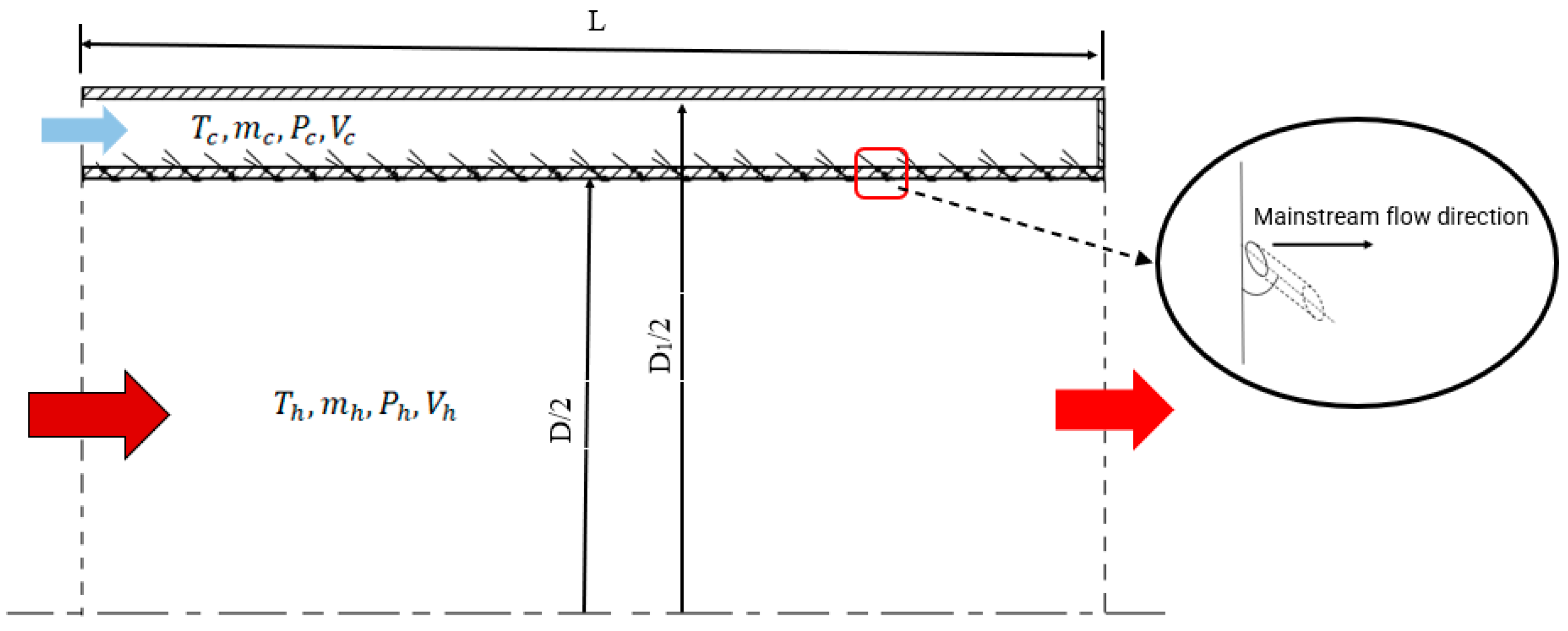
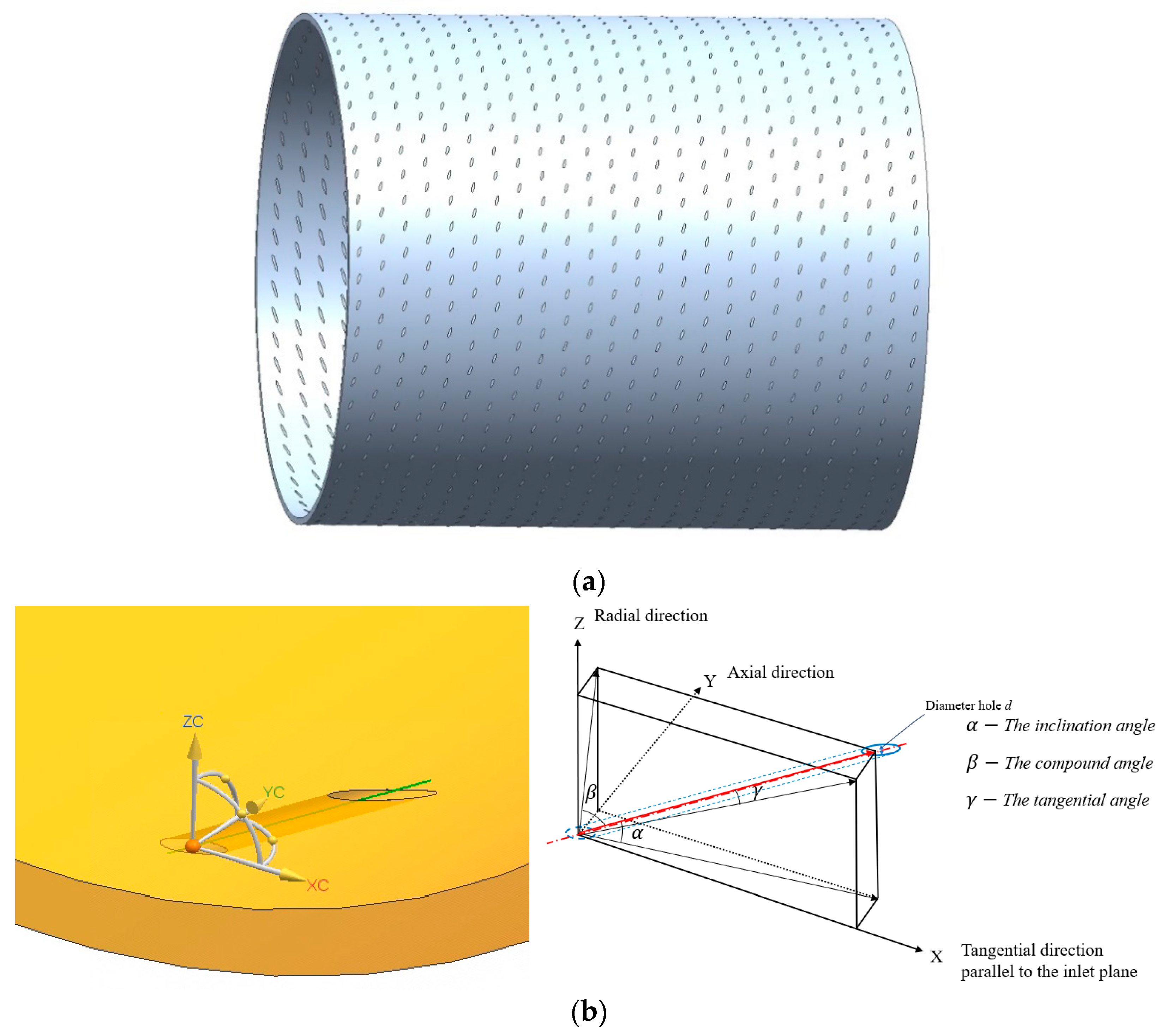
2.1. Geometry Description
2.2. Boundary Conditions
3. Mathematical and Numerical Modeling
3.1. Turbulence Model
3.2. Radiation Modeling
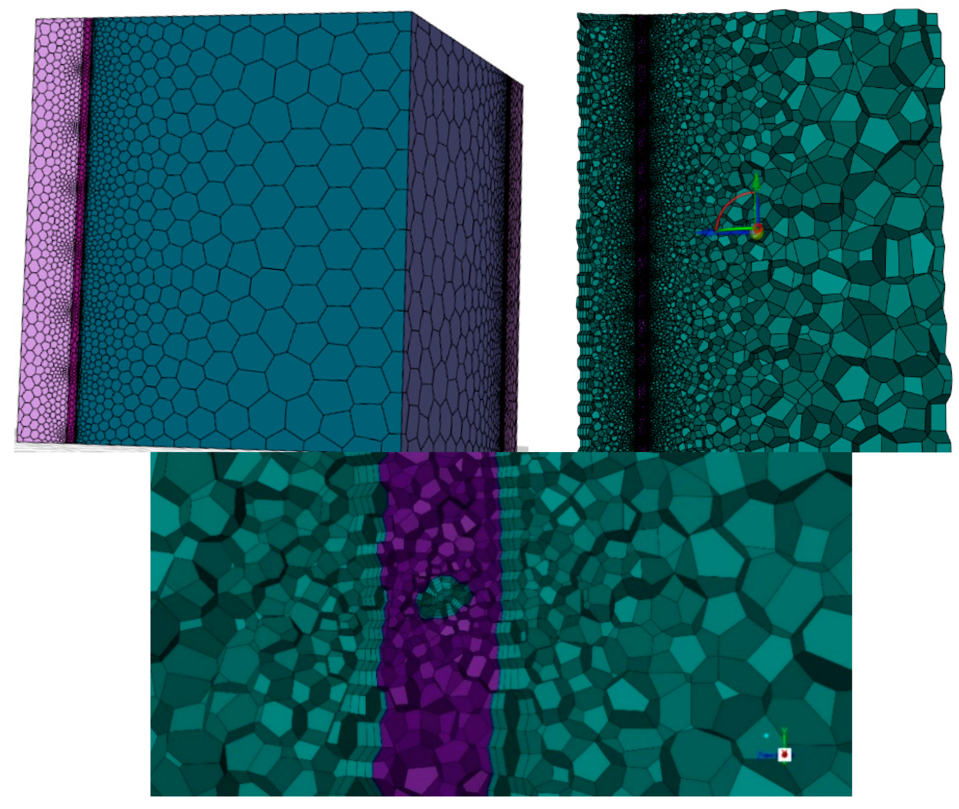
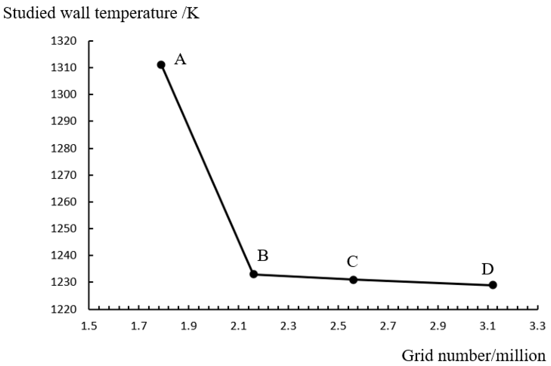
3.3. Mesh and Independence Study
4. Results and Analysis
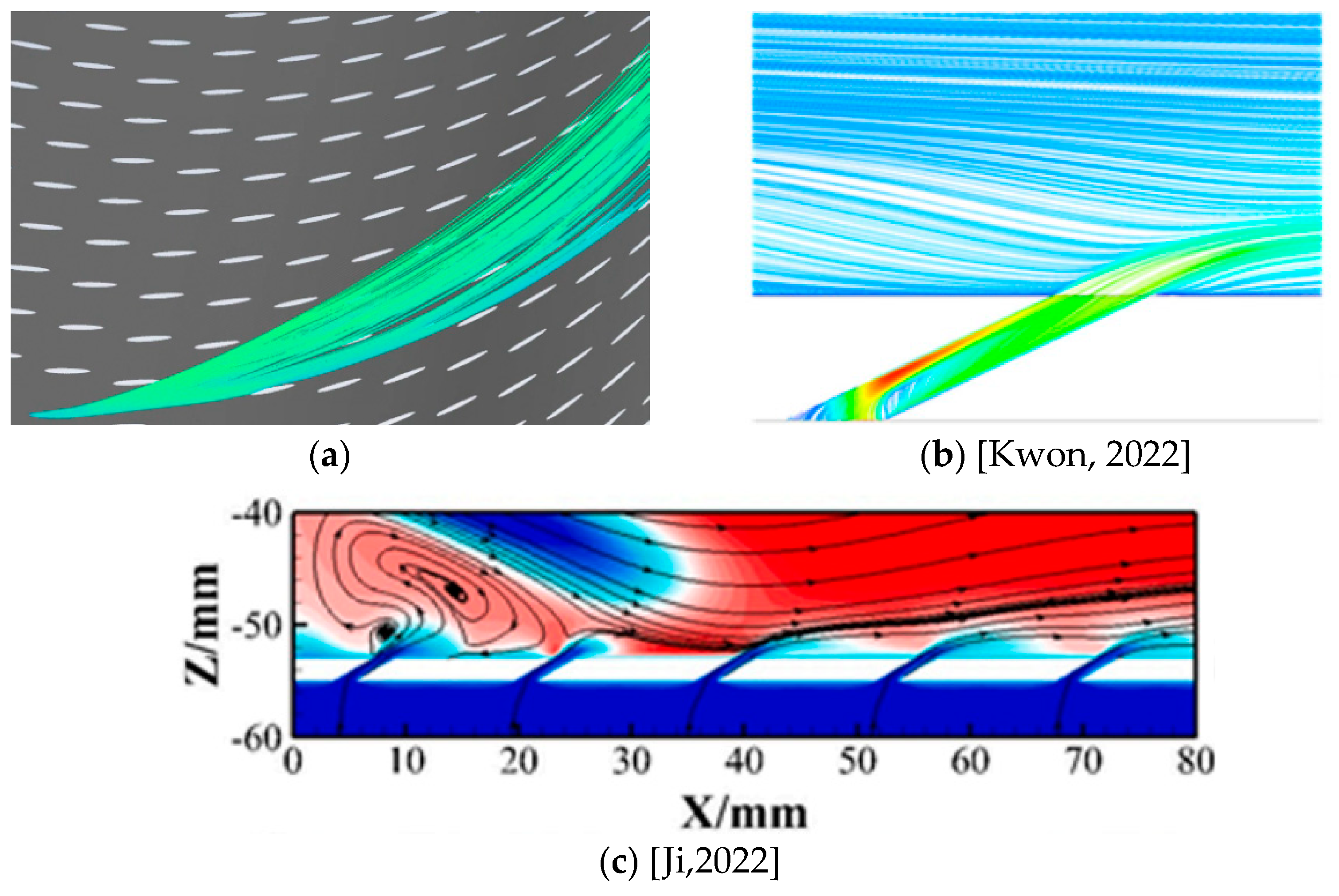
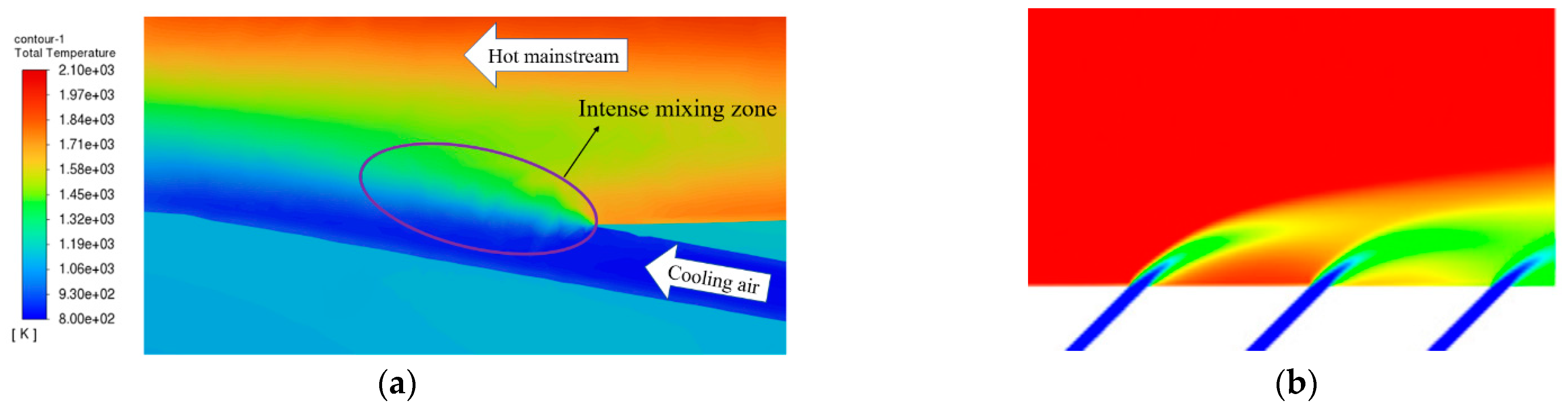
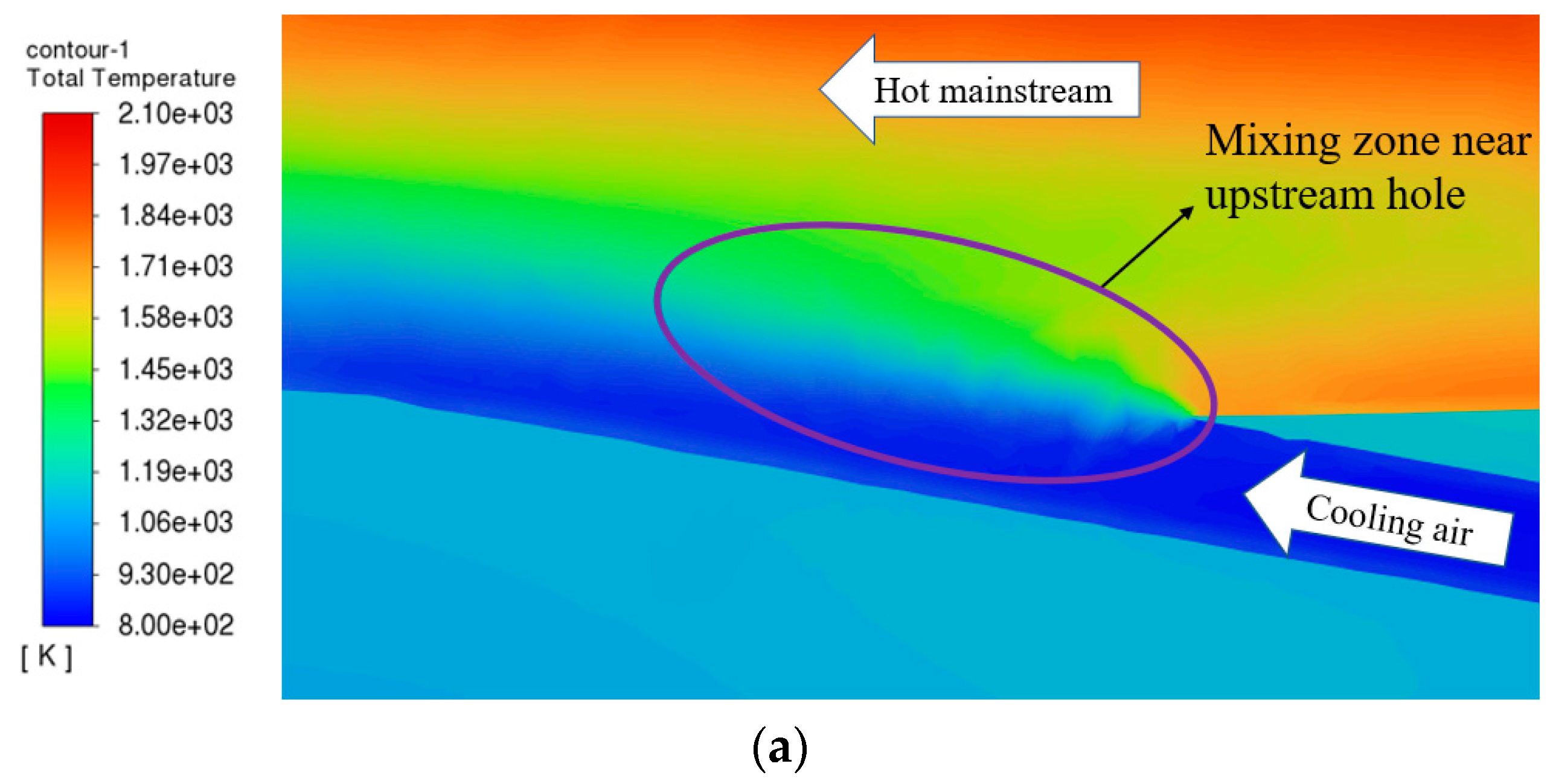
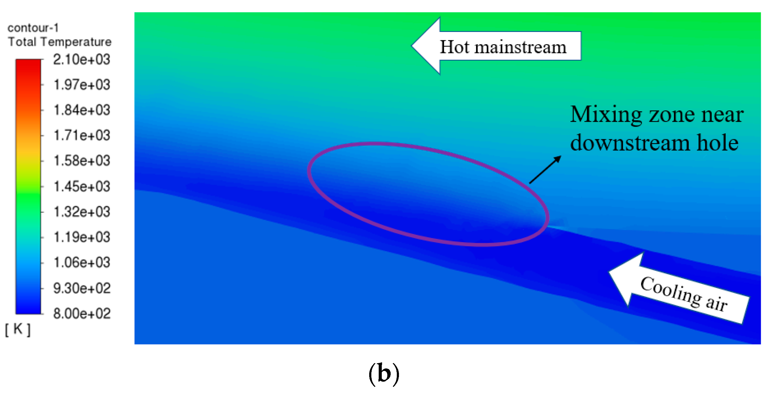
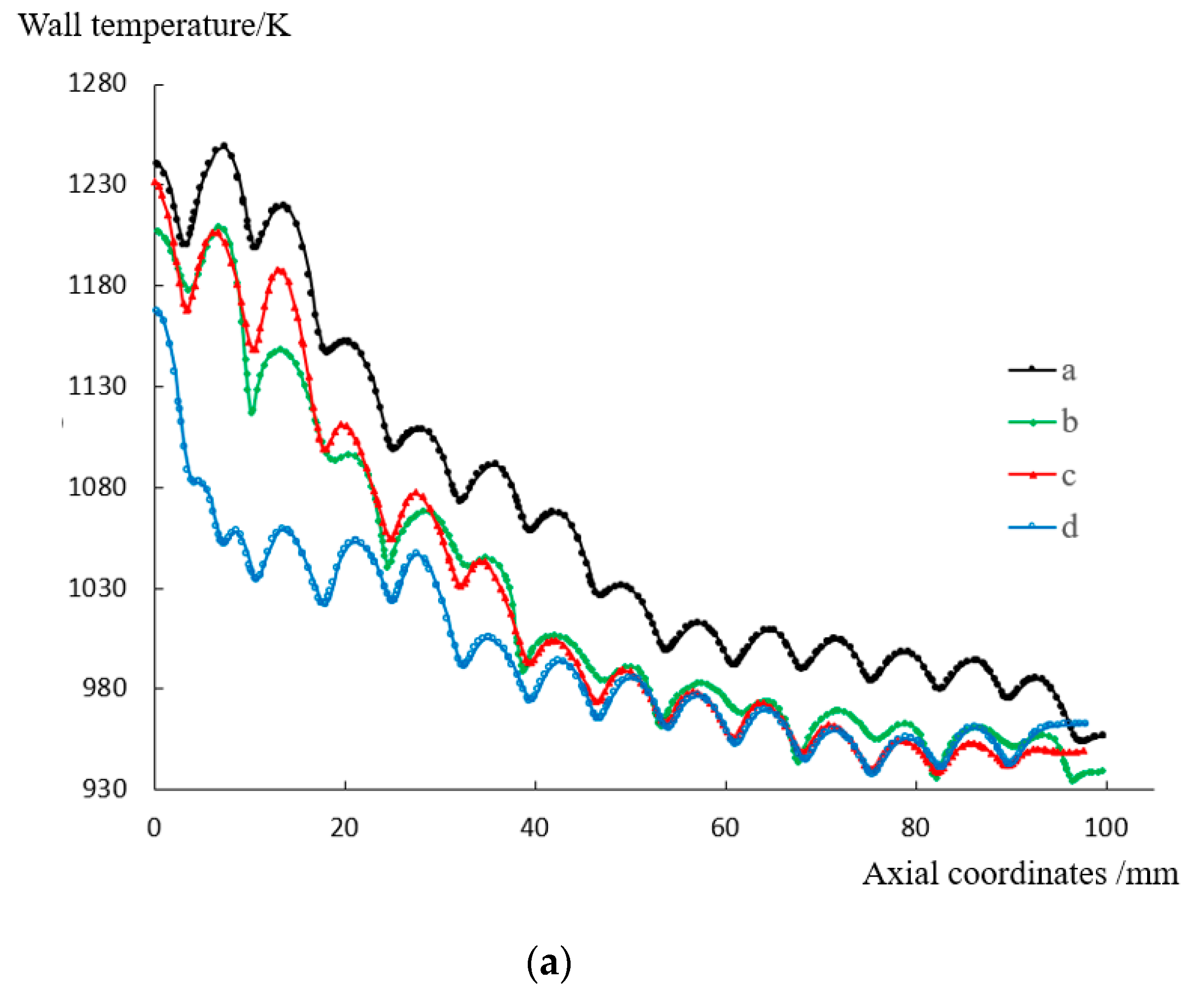
4.1. Flow and Heat Transfer Characteristics of the Film
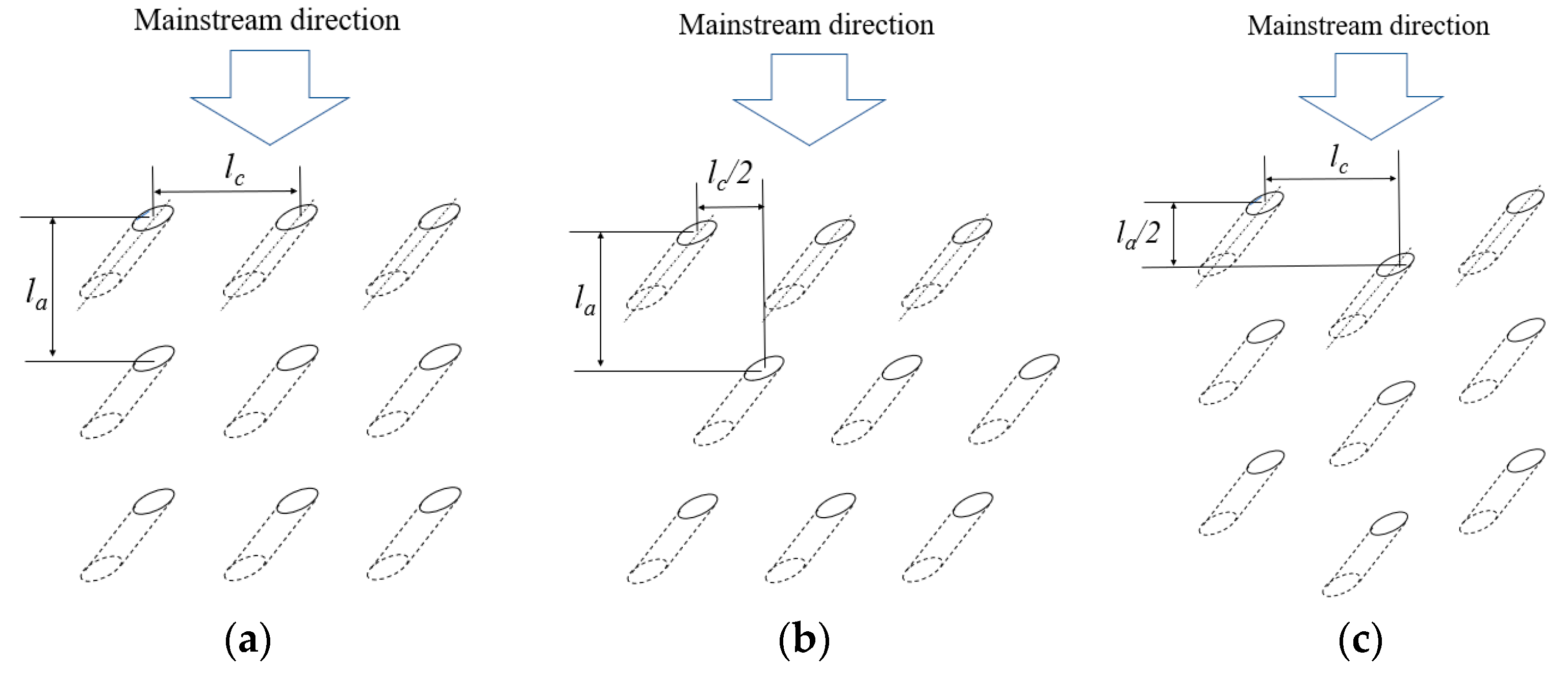
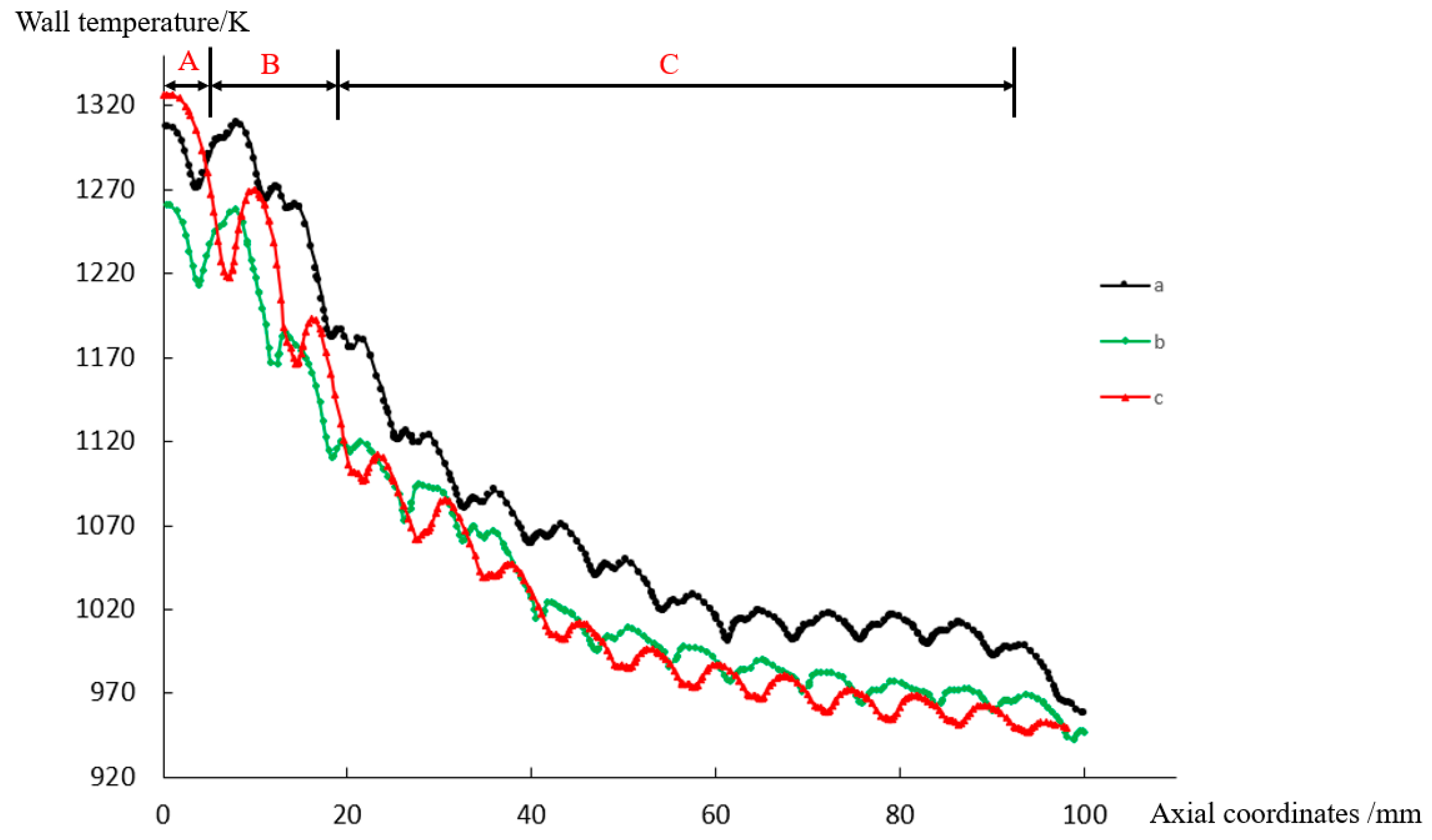
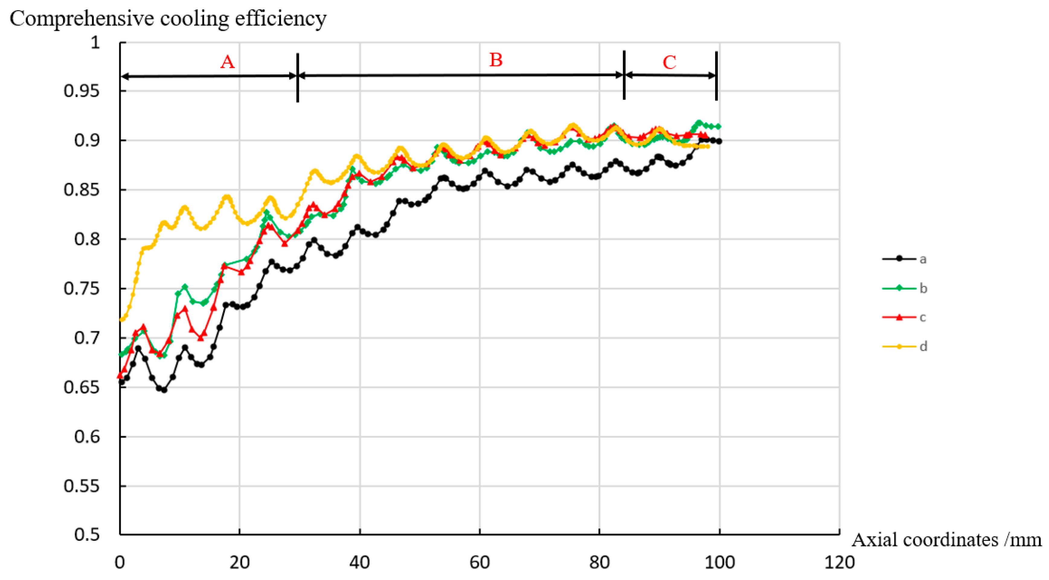
4.2. Comparative Study of the Influence of Different Cooling Hole Arrangements on the Cooling Efficiency
4.3. Analysis and Summary
- (1)
- Unit cooling area of the cooling hole
- (2)
- Interaction between the upstream and downstream jets
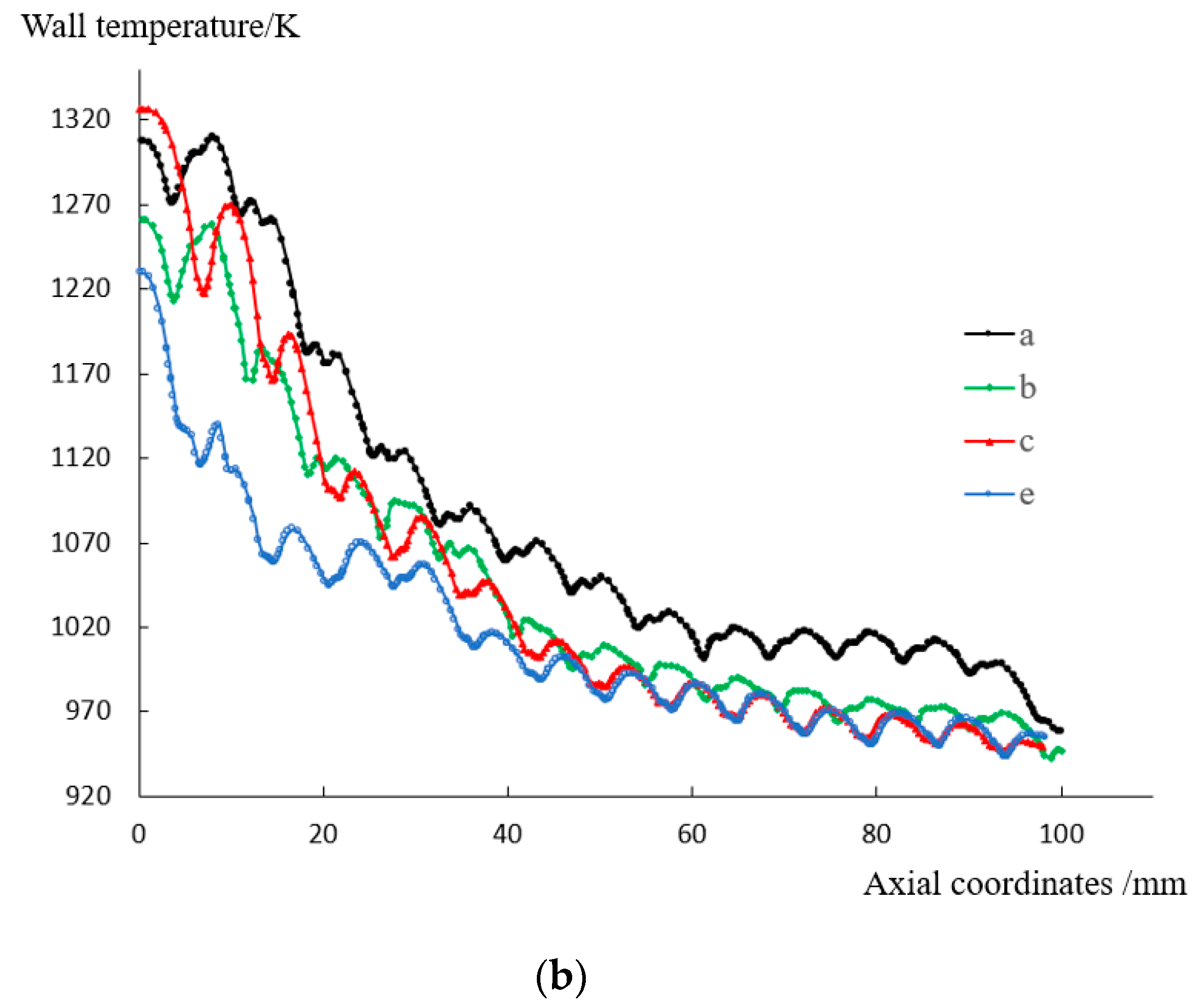
4.4. Improved Cooling Hole Arrangement
5. Conclusions
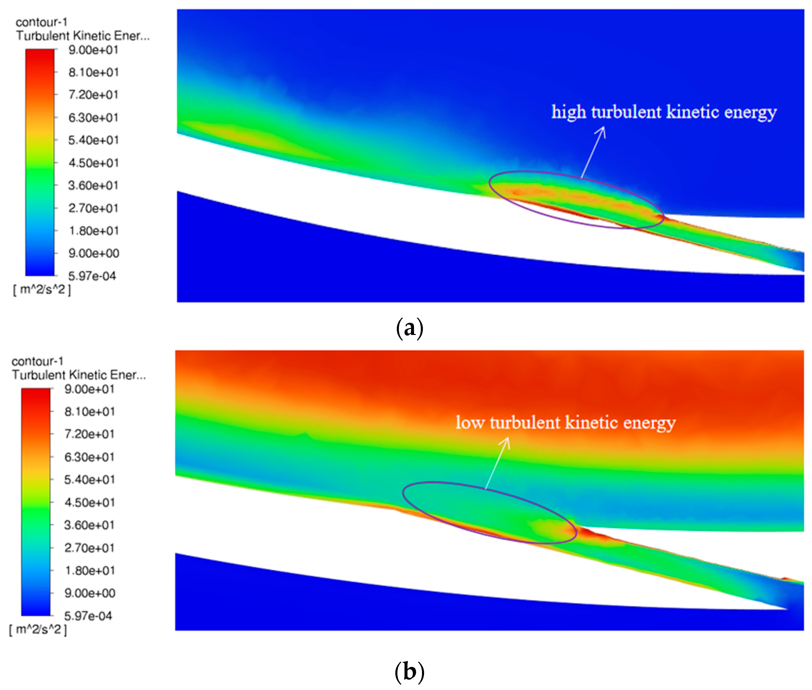
- For the tangential effusion cooling, the cooling jet flows spirally onwards and tightly adheres to the inner surface after entering the liner, and it is then distributed in a divergent “horsetail” shape on the inner wall of the liner. For the traditional effusion cooling of a flat plate, most of the cooling jets quickly integrate into the mainstream.
- For the tangential effusion cooling, intensive heat and mass exchange occur mainly at the zone around the upper edge/lip of the cooling hole exit. An appropriate arrangement of cooling holes could make the cooling jet tightly “compressed” by the upstream jets, which reduces the turbulence intensity around the cooling jets, thus reducing the heat and mass exchange between the cooling jets and mainstream, and increasing the cooling effectiveness.
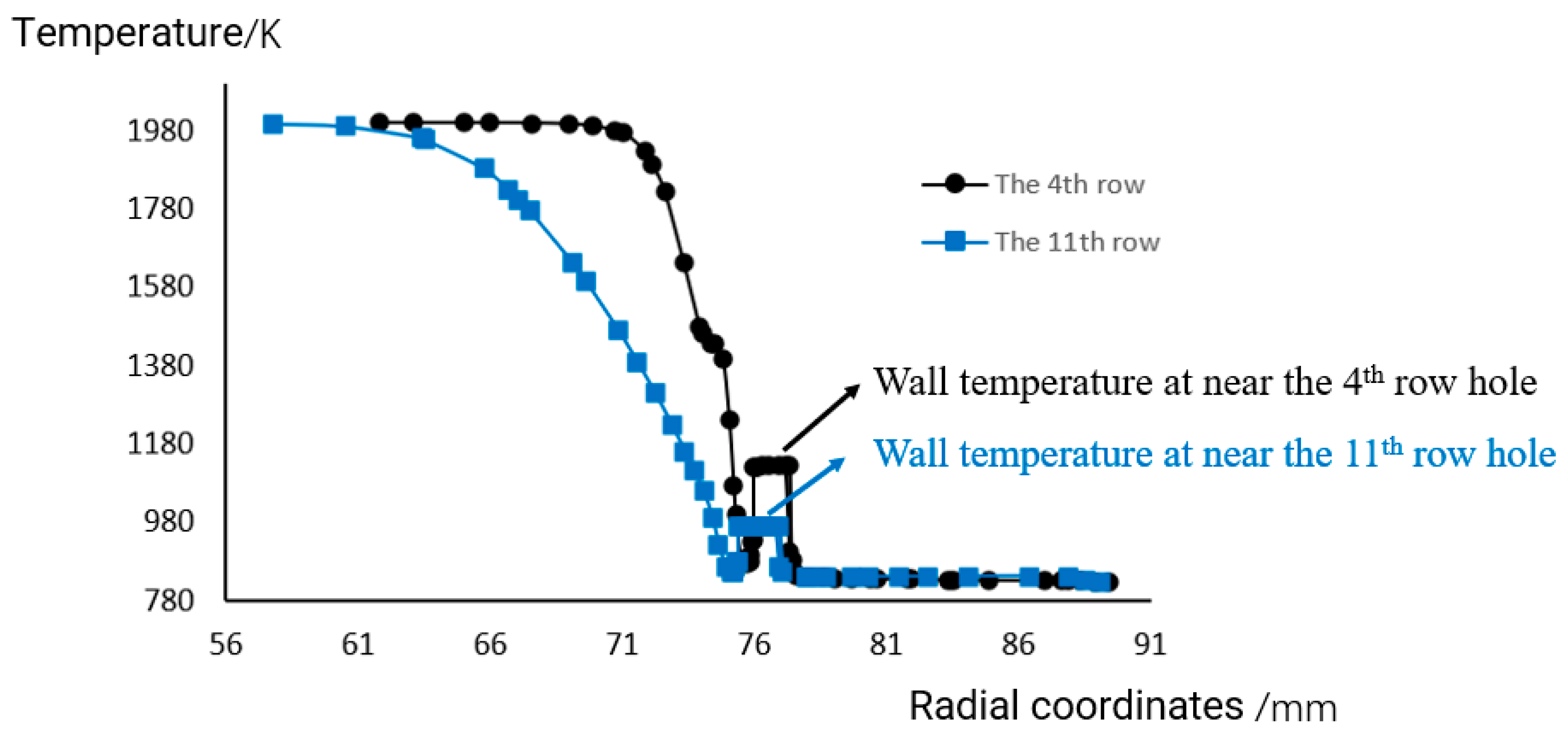
- The temperature of the liner wall near a cooling hole is higher than the temperature of the cooling film formed on the inner wall surface, indicating that for this type of cooling, the increase in the liner wall temperature mainly comes from the radiation heat transfer from the high-temperature mainstream, and the convective heat transfer direction between the wall and the cooling film is from the wall to the film.
- Three different arrangements of cooling holes are compared, and the unit cooling area of a hole is defined. It is found that and the distances between an upstream jet and the downstream adjacent jets S1 and S2 have a great influence on the cooling efficiency. The axially staggered 1/2 column arrangement has the highest comprehensive cooling efficiency due to the smallest and the smallest variance in S1 and S2.
- Based on the theoretical analysis and comparative studies, the cooling hole arrangement is improved based on the axially staggered 1/2 column arrangement (arrangement “c”), i.e., the first and second rows of cooling holes are doubled. The calculation results show that this improvement method significantly increases the cooling efficiency for the liner wall without increasing the flow rate of the cooling air, and the maximum local temperature is decreased from 1330 K to 1235 K, which is already lower than the long-term operating limited temperature of nickel-based high-temperature alloys, such as GH5188.
Author Contributions
Funding
Data Availability Statement
Conflicts of Interest
Nomenclature
| D | Inner diameter of the combustor liner, mm |
| D1 | Inner diameter of the combustor case, mm |
| T | Temperature, K |
| V | Velocity, m/s |
| Inclination angle | |
| Tangential angle | |
| la | Axial spacing of holes |
| n | Number of adjacent nearest holes |
| S1 | Distance between an upstream cooling jet and an adjacent downstream cooling jet |
| Variance in and | |
| L | Length of the combustor liner, mm |
| m | Mass flow rate, kg/s |
| P | Total pressure, Pa |
| d | Diameter of effusion holes, mm |
| Compound angle | |
| lc | Circumferential spacing of holes |
| A | Area enclosed between adjacent holes |
| Unit cooling area of a hole | |
| S2 | Distance between an upstream cooling jet and the other adjacent downstream cooling jet |
| Subscripts | |
| w | Wall |
| h | Hot |
| c | Cold |
References
- Baocheng, Z. Status and Development of Aeroengine Combustors. Aeroengine 2013, 39, 67–73. [Google Scholar]
- Chuanliang, Z.; Yao, H.; Hongyu, M.; Shoutang, S.H.N. Development and Application of Heat Resisting Techniques for Gas Turbine Combustor Liner. Aeroengine 2016, 42, 47–54. [Google Scholar]
- Lefebvre, A.; Ballal, D. GAS Turbine Combustion; CRC Press: Boca Raton, FL, USA, 2010. [Google Scholar]
- Rushan, J.; Jianqin, S. Advanced Gas Turbine Combustor; Aviation Industry Press: Beijing, China, 2016. [Google Scholar]
- Pengfeng, Z.; Wenzhe, C. A Review of Advanced Cooling Technology for Combustor Based on Micro-hole. Tactical Missile Technol. 2018, 2, 95–101. [Google Scholar]
- Shumin, W. Advanced Gas Turbine Combustor Design and Development; Shanghai Jiao Tong University Press: Shanghai, China, 2014. [Google Scholar]
- Click, A.; Ligrani, P.M.; Hockensmith, M.; Knox, J.; Larson, C.; Fairbanks, A.; Liberatore, F.; Patel, R.; Ho, Y.-H. Louver Slot Cooling and Full-Coverage Film Cooling With a Combination Internal Coolant Supply. ASME Trans. J. Turbomach. 2021, 143, 031004. [Google Scholar] [CrossRef]
- Bergeles, G.; Gosman, A.D.; Launder, B.E. Double-Row Discrete Holes Cooling: An Experimental an Numerical Study. ASME J. Eng. Power 1980, 102, 498–503. [Google Scholar] [CrossRef]
- Afejuku, W.O.; Hay, N.; Lampard, D. The film cooling effectiveness of double rows of holes. J. Eng. Power Trans. ASME 1980, 102, 601–607. [Google Scholar] [CrossRef]
- Kadotani, K.; Goldstein, R.J. Effect of Mainstream Variables on Jets Issuing from a Row of Inclined Round Holes; ASME Paper No. 78-GT-138; ASME: New York, NY, USA, 1978. [Google Scholar]
- Brown, A.; Saluja, C.L. Film Cooling from Three rows of Holes on Adiabatic, Constant Heat Flux and Isothermal Surfaces in the Presence of Variable Velocity Gradients and Turbulent Intensity; ASME Paper No.79j-GT-24; American Society of Mechanical Engineers: New York, NY, USA, 1979. [Google Scholar]
- Wang, J.; Hu, Z.; Du, C.; Tian, L.; Baleta, J. Numerical study of effusion cooling of a gas turbine combustor liner. Fuel 2021, 294, 120578. [Google Scholar] [CrossRef]
- Wei, H.; Zu, Y.; Ai, J.; Ding, L. Experimental study on the full-coverage film cooling of fan-shaped holes with a constant exit width. Int. J. Heat Mass Transf. 2019, 140, 379–398. [Google Scholar] [CrossRef]
- Zong, C.; Ji, C.; Cheng, J.; Zhu, T. Comparison of adiabatic and conjugate heat transfer models on near-wall region flows and thermal characteristics of angled effusion cooling holes. Therm. Sci. Eng. Prog. 2022, 30, 101269. [Google Scholar] [CrossRef]
- Goldstein, R.J.; Jin, P. Film Cooling Downstream of a Row of Discrete Holes with Compound Angle. J. Turbomach. 2001, 123, 222–230. [Google Scholar] [CrossRef]
- Chen, P.H.; Hung, M.S.; Ding, P.P. Film Cooling Performance on Curved Walls with Compound Angle Hole Configuration. Ann. New York Acad. Sci. 2010, 934, 353–360. [Google Scholar] [CrossRef]
- Natsui, G.; Claretti, R.; Ricklick, M.A.; Kapat, J.S.; Crawford, M.E.; Brown, G.; Landis, K. Experimental Evaluation of Large Spacing Compound Angle Full-Coverage Film Cooling Arrays: Adiabatic Film Cooling Effectiveness. J. Turbomach. 2016, 138, 071001. [Google Scholar] [CrossRef]
- Ekkad, S.V.; Zapata, D.; Han, J.C. Film Effectiveness over a Flat Surface with Air and CO2 Injection through Compound Angle Holes Using a Transient Liquid Crystal Image Method. J. Turbomach. 1997, 119, 587–593. [Google Scholar] [CrossRef]
- Lee, H.W.; Park, J.J.; Lee, J.S. Flow Visualization and Film Cooling Effectiveness Measurements around Shaped Holes with Compound Angle Orientations. Int. J. Heat Mass Transf. 2002, 45, 145–156. [Google Scholar] [CrossRef]
- Michel, B.; Gajan, P.; Strzelecki, A.; Savary, N.; Kourta, A.; Boisson, H.-C. Full coverage film cooling using compound angle. C. R. Mécanique 2009, 337, 562–572. [Google Scholar] [CrossRef]
- Walters, D.K.; Leylek, J.H. A Detailed Analysis of Film–Cooling Physics: Part I—Streamwise Injection with Cylindrical Holes. J. Turbomach. 2000, 122, 102–112. [Google Scholar] [CrossRef]
- McGovern, K.T.; Leylek, J.H. A Detailed Analysis of Film Cooling Physics: Part II—Compound-Angle Injection with Cylindrical Holes. J. Turbomach. 2000, 122, 113–121. [Google Scholar] [CrossRef]
- Hyams, D.G.; Leylek, J.H. A Detailed Analysis of Film Cooling Physics: Part III—Streamwise Injection with Shaped Holes. J. Turbomach. 2000, 122, 123–132. [Google Scholar] [CrossRef]
- Brittingham, R.A.; Leylek, J.H. A Detailed Analysis of Film Cooling Physics: Part IV—Compound–Angle Injection with Shaped Holes. J. Turbomach. 2000, 122, 133–145. [Google Scholar] [CrossRef]
- Chin, J. Design of Aero Engine Lean Direct Mixing Combustor. In Proceedings of the 2018 Joint Propulsion Conference, Cincinnati, OH, USA, 9–11 July 2018. [Google Scholar] [CrossRef]
- Chin, J. Suggestions on High Temperature Rise Combustor. In Proceedings of the AIAA Propulsion and Energy 2019 Forum, Indianapolis, IN, USA, 19–22 August 2019. [Google Scholar] [CrossRef]
- Chin, J.; Dang, J. New Generation Aero Combustor; Intech Open Access Publisher: Vienna, Austria, 2020. [Google Scholar]
- Wang, T.; Suo, J.; Liang, H. Numerical study of tangential effusion cooling for combustor liner. J. Aerosp. Power 2011, 26, 1052–1058. [Google Scholar]
- Guang, Y.; Weiwei, S.; Zhedian, Z. Experimental and numerical study on heat transfer characteristics of tangential effusion cooling for a combustor liner. Appl. Therm. Eng. 2023, 218, 119374. [Google Scholar]
- Xinshuo, D. Fluent 17.0 Fluid Simulation: From Beginner to Proficient; Tsinghua University Press: Beijing, China, 2018. [Google Scholar]
- Qinghua, Z.; Yixiang, Y. Flow dynamics of dual-stage counter-swirl combustor in different confinement spaces. Int. Commun. Heat Mass Transf. 2020, 116, 104633. [Google Scholar]
- Li, Z.; Yuan, Y.; Guo, B.; Varsegov, V.L.; Yao, J. The Recirculation Zone Characteristics of the Circular Transverse Jet in Crossflow. Energies 2020, 13, 3224. [Google Scholar] [CrossRef]
- Kwon, H.; Ligrani, P.M.; Vanga, S.R.; Park, H. Flow structure and surface heat transfer from numerical pre-dictions for a double wall effusion plate with impingement jet array cooling. Int. J. Heat Mass Transf. 2022, 183, 122049. [Google Scholar] [CrossRef]
- Hjärtstam, S.; Johansson, R.; Andersson, K.; Johnsson, F. Computational Fluid Dynamics Modeling of Oxy-Fuel Flames: The Role of Soot and Gas Radiation. Energy Fuels 2012, 26, 2786–2797. [Google Scholar] [CrossRef]
- Liu, Y.; Rao, Y.; Yang, L. Numerical simulations of a double-wall cooling with internal jet impingement and external hexagonal arrangement of film cooling holes. Int. J. Therm. Sci. 2020, 153, 106337. [Google Scholar] [CrossRef]
- Ji, Y.; Ge, B.; Zang, S. Analysis of effusion cooling under realistic swirl reacting flow in gas turbine combustor. Appl. Therm. Eng. 2022, 216, 119101. [Google Scholar] [CrossRef]
- Venkatesh, V.; Sriraam, J.; Subhash, K.; Velamati, R.K.; Srikrishnan, A.R.; Ramakrishnananda, B.; Batchu, S. Studies on effusion cooling: Impact of geometric parameters on cooling effec-tiveness and coolant consumption. Aerosp. Sci. Technol. 2018, 77, 58–66. [Google Scholar] [CrossRef]


| Mass flow of the mainstream, mh | 898.98 g/s |
| Mainstream temperature, Th | 2000 K |
| Mainstream total pressure, ph | 2,989,600 Pa |
| Mass flow of the secondary flow, mc | 284.16 g/s |
| Secondary flow temperature, Tc | 840 K |
| Secondary flow total pressure, pc | 3,180,400 Pa |
| Temperature of the secondary flow wall | 800 K |
| Temperature °C | Density g/cm3 | Thermal Conductivity W/(m·°C) | Specific Heat Capacity J/(kg·°C) |
|---|---|---|---|
| 500 | 9.09 | 20.81 | 513 |
| 600 | 22.90 | 534 | |
| 700 | 25.04 | 554 | |
| 800 | 26.50 | 571 | |
| 900 | 27.88 | 588 | |
| 1000 | 29.06 | 600 |
| No. | Turbulence Model | Accuracy (Percent) |
|---|---|---|
| 1 | k-ω SST turbulence model | 1.3% |
| 2 | k-ε standard | 4% |
| 3 | k-ε realizable | 27.0% |
| 4 | RSM—linear pressure strain | 20.6% |
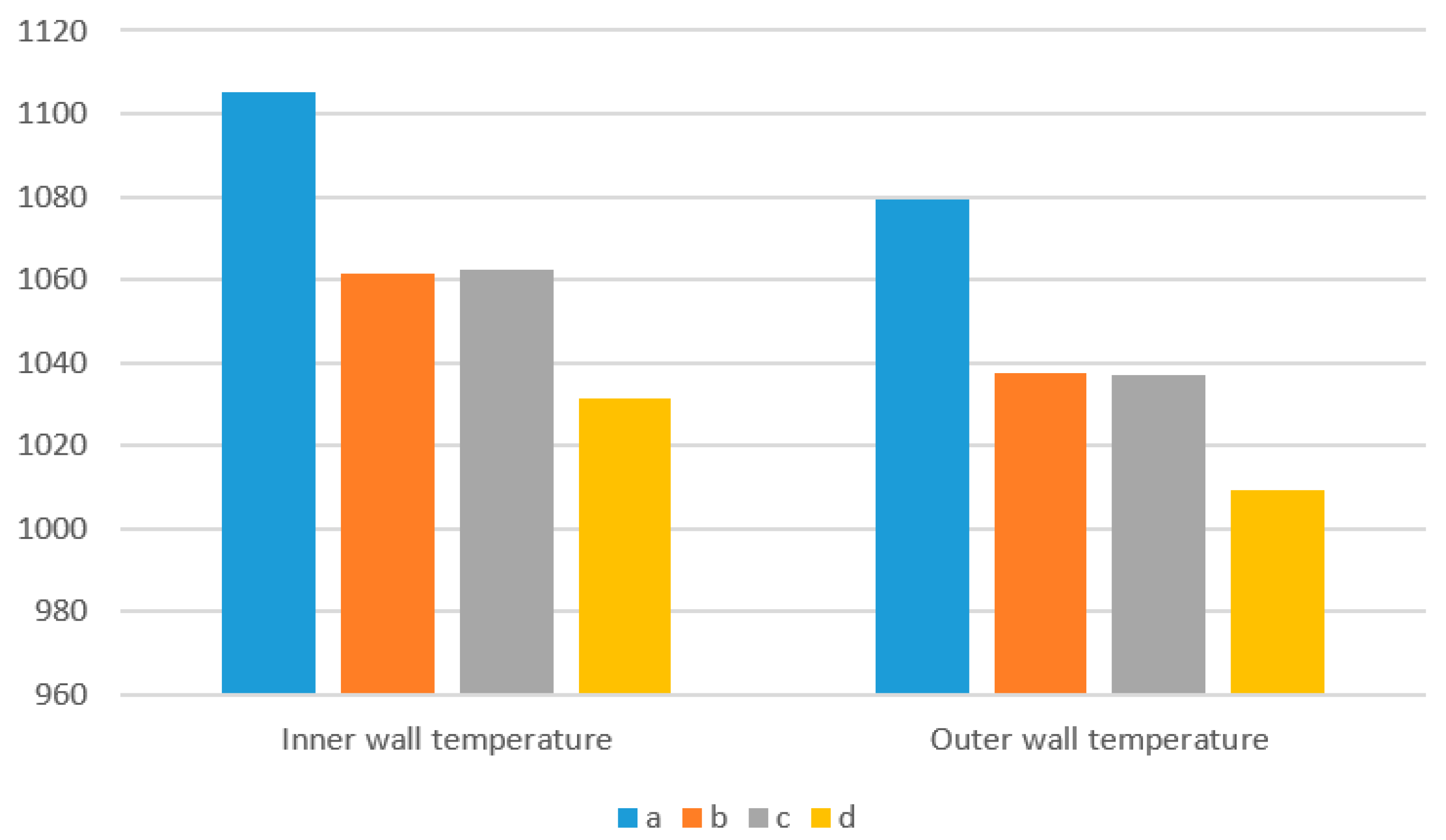
| Cooling Hole Arrangement | Outer Wall Temperature of the Liner, K | Inner Wall Temperature of the Liner, K |
|---|---|---|
| Arrangement “a” | 1079.36 | 1105.35 |
| Arrangement “b” | 1037.39 | 1061.47 |
| Arrangement “c” | 1037.20 | 1062.34 |
Disclaimer/Publisher’s Note: The statements, opinions and data contained in all publications are solely those of the individual author(s) and contributor(s) and not of MDPI and/or the editor(s). MDPI and/or the editor(s) disclaim responsibility for any injury to people or property resulting from any ideas, methods, instructions or products referred to in the content. |
© 2023 by the authors. Licensee MDPI, Basel, Switzerland. This article is an open access article distributed under the terms and conditions of the Creative Commons Attribution (CC BY) license (https://creativecommons.org/licenses/by/4.0/).
Share and Cite
Li, Z.; Xie, P.; Zeng, Q.; Chen, X. Study of Tangential Effusion Cooling of a Combustor Liner. Processes 2023, 11, 2433. https://doi.org/10.3390/pr11082433
Li Z, Xie P, Zeng Q, Chen X. Study of Tangential Effusion Cooling of a Combustor Liner. Processes. 2023; 11(8):2433. https://doi.org/10.3390/pr11082433
Chicago/Turabian StyleLi, Ziwan, Pengfu Xie, Qinghua Zeng, and Xuanwu Chen. 2023. "Study of Tangential Effusion Cooling of a Combustor Liner" Processes 11, no. 8: 2433. https://doi.org/10.3390/pr11082433