1. Introduction
With the continuous development of general aviation, small unmanned aerial vehicles (UAV) gradually emerging, two-stroke engines with low fuel consumption, low failure rate, low noise, and light mass are widely used [
1]. Compared with the traditional turbocharger, the electric supercharger can improve the combustion quality of the engine and reduce the emission of smoke and fuel consumption rate, which has a certain effect on environmental protection. Moreover, it can improve the engine dynamics, especially in the low-speed and high-torque operating conditions [
2,
3,
4,
5,
6,
7].
Centrifugal compressors, as the main components of electric pressure intensifiers, are characterized by small size, simple structure, and high boost ratio, and their main structures are the diffuser, impeller, and worm housing [
8]. The design of the diffuser and impeller has an essential impact on the performance of the pressurizer, so the current research on the pressurizer is mainly reflected in the analysis and optimization of its implementation [
9,
10,
11,
12,
13]. The diffuser increases the pressure of the compressed medium and reduces the medium’s velocity through the expansion of the flow channel. The bladeless diffuser is widely used in compressors because of its simple structure, good adaptability, and wide working range compared to the vane diffuser [
14]. Seralathan and Roy analyzed the effect of the bladeless diffuser on the compressor performance by numerical simulation: when the diffuser flow angle is small, the flow path length is shorter, the impeller friction loss is reduced, and the compressor efficiency is increased [
15]. Chen et al. used the method of appropriately increasing the bladeless area, which can significantly reduce the separation loss and make the flow velocity at the impeller outlet and diffuser inlet uniform, which improves the performance of the compressor [
16]. Ma and Li reduced the solidity of the blade diffuser and slotted the hub side of the diffuser impeller, which can make the compressor more efficient [
17]. Gunadal and Govardhan investigated the relationship between blade angle and compressor performance in a bladed diffuser, and, when the diffuser blade tilt was 6°, the stall margin and operating range were improved, and the compressor pressure ratio was also increased [
18].
The impeller also has an important impact on the performance improvement of the compressor, so a lot of research work has been carried out by scholars in the design optimization of the compressor [
19,
20,
21,
22]. Li et al. studied a set of high-speed compressor impellers with different geometries and analyzed the secondary flow model, where the ratio of impeller inlet diameter to outlet diameter has an effect on the impeller flow uniformity, which, in turn, affects the compressor efficiency [
23]. Yang et al. modified the hub alignment to investigate the effect of hub curvature on the performance of the compressor [
24]. Hong et al., through numerical simulations of a centrifugal compressor for a hydrogen-powered fuel electric vehicle, found that the generation of leaf top leakage, hub separation, and horseshoe vortex structure determined the degree of the aerodynamic performance of the centrifugal compressor [
25]. Jaatinen-Värri et al. studied that impellers with different top clearance and spreading width, and found that increasing the top clearance can significantly increase the reverse flow in the impeller, which will mix with the top clearance flow, leading to a reduction in impeller wake loss and an increase in compressor efficiency [
26].
This article makes the following contributions: (1) Designing a centrifugal compressor for the electric turbocharger by exploring the internal flow field of the compressor through numerical simulations of the initial model; (2) Analyzing the impact of impeller blade number, relative outlet width, and impeller backbend angle on compressor performance and optimizing the initial model to determine whether optimized performance is improved over initial performance; (3) Experimentally verifying whether the optimized compressor performs according to the design requirements.
The main sections of this article are as follows.
Section 2 introduces the theoretical foundation of numerical simulation and formulates the initial model of the compressor.
Section 3 analyzes the effects of the impeller blade number, relative outlet width, and impeller backbend angle on the compressor’s performance and flow field, evaluating the optimized compressor model.
Section 4 outlines the experimental procedure, while
Section 5 outlines the main conclusions of the research.
2. Centrifugal Compressor Modeling and Numerical Simulation
This chapter introduces the theoretical background of compressor numerical simulation and presents the procedures for designing a compressor model, grid division, discretization, and performance analysis. The factors affecting the compressor performance are investigated.
2.1. Numerical Simulation Theory
Numerical simulation methods [
27] allow accurate and efficient analysis of the flow and heat transfer in the compressor model. In this paper, the numerical calculations are mainly performed using the Euranus solver in FineTurbo, and the Spalart-Allmaras equation turbulence model is selected to solve the RANS equations. The RANS equations are obtained by Re averaging the conventional mass conservation equation, momentum conservation equation, and energy conservation equation, where the mass conservation equation is expressed as:
where
is the fluid density;
t is the time;
is the spatial coordinate position;
i is the three directions in space; and
is the velocity in the direction.
The conservation of momentum equation is:
where
is the combined pressure force acting on the fluid microcluster;
v is the kinematic viscosity coefficient of the fluid;
;
is the Reynolds stress term;
is the spatial coordinate position;
j denotes the three directions of space;
,
is the velocity of the fluid microcluster in the
,
direction, respectively; and
,
is the velocity of the pulsating mass in the
,
direction, respectively.
The conservation of energy equation is:
where
is the total energy of the fluid microcluster;
is the thermal conductivity;
is the temperature; and
is the energy source term. The finite difference method and finite volume method are used to discretize the control method.
The SA turbulence model contains turbulent viscosity, generation, and dissipation terms.
The turbulent viscosity is:
where
represents is the Spalart-Allmaras variable [
28], with
expressed as follows:
where
is the ratio between the turbulent fluctuation velocity
and the molecular viscosity
v. The turbulent fluctuation velocity
is obtained from the following equation:
where
is the average velocity vector;
is the source term,
and
is a constant.
consists of a generating term and a dissipative term, and the expression is as follows:
where
where the expression of
,
g, and
r are as follows:
where the constant term is shown below:
where
= 0.3,
= 2,
= 7.2,
= 5,
= 0.1357,
= 0.619,
= 0.41,
.
2.2. Compressor Modeling
As shown in
Table 1, the design index of the centrifugal compressor is that the total pressure ratio of the compressor is more significant than 1.4, the isentropic efficiency is greater than 0.75, and the working margin is greater than 15% under the condition that the speed is 70,000 r/min and the air mass flow rate is 0.027 kg/s. The design needs to meet the above requirements.
This paper explores the design of the impeller and diffuser for centrifugal compressors. The impeller inlet design [
29,
30] considers various parameters, such as rim diameter and hub diameter. The impeller inlet rim diameter has an enormous impact on the performance of the compressor. At the same mass flow rate, a smaller rim diameter can reduce the hub diameter, which reduces the tip Mach number and plays a role in improving the downstream flow field of the impeller; if the hub diameter is too large, the local Mach number of the compressor will reach transonic velocity and generate surge phenomenon in the leading-edge region of the blade, which, in turn, will produce flow separation. Impeller outlet design [
31,
32] mainly considers impeller diameter, impeller outlet width, and outlet blade angle. Increasing the impeller diameter significantly enhances its work capacity and pressure ratio, but excessively enlarging it will increase the impeller’s circumferential velocity, thereby affecting its safe operation. The impeller outlet width mainly affects the impeller import and export speed ratio, and, if the impeller outlet width is too small, it will lead to the top of the impeller and a significant increase in the impact of gap leakage. The impeller outlet blade angle significantly affects the impeller’s aerodynamic performance. The backward curved impeller sufficiently reduces the impeller outlet flow rate, regardless of the subsequent stationary parts, which enhances its performance. Its conditions range widely compared to the forward curved and radial impellers, and it also weakens the strength of the secondary flow inside the impeller, which increases compressor efficiency. Hence, this paper adopts the backward curved impeller.
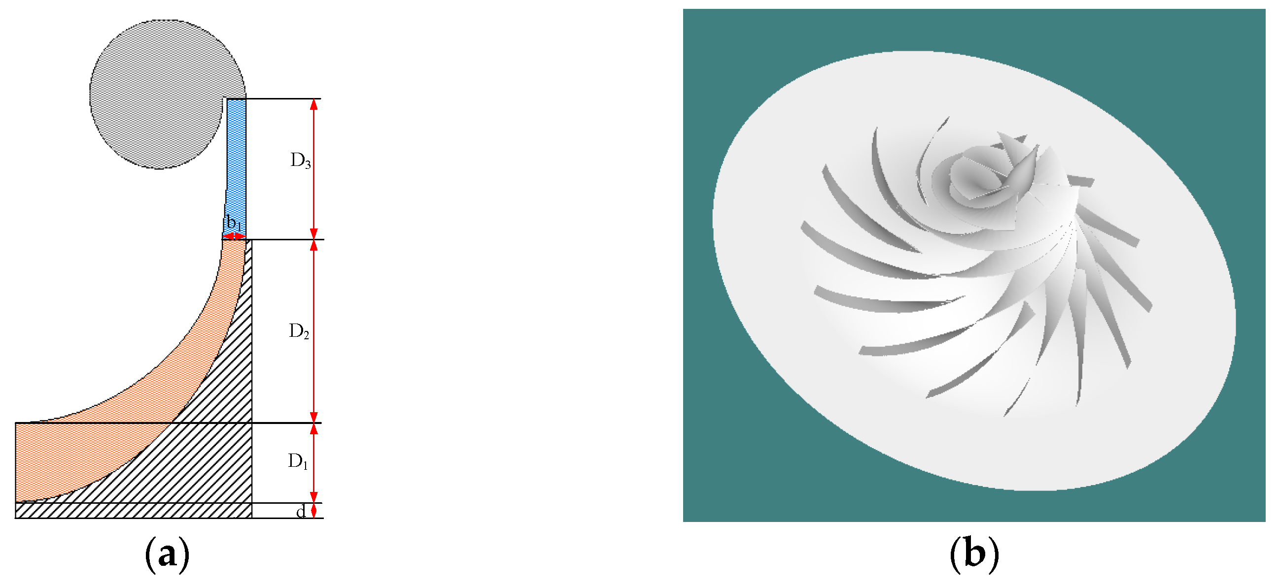
This paper presents a bladeless diffuser, with the main focus on the ratio of the diffuser diameter D3 to the impeller diameter D2, referred to as f1. Studies indicate that a value of f1 equal to 1 results in better diffuser performance; however, for this design, a value of 0.8 for f1 is considered. Additionally, the ratio of the diffuser inlet width b1 to the impeller outlet width f2 is typically between 1 and 1.1. Thus, the value of f2 is set to 1 in this design, resulting in b1 being equal to the impeller outlet width for consistency.
According to the above requirements, the relevant geometric parameters of the compressor are designed, and the results are shown in
Table 2, which are input into the compal to generate the meridional flow channel surface, as shown in
Figure 1a.
D1 is the impeller inlet diameter,
d is the impeller inlet hub diameter,
D2 is the impeller outlet diameter,
b1 is the impeller outlet width, and
D3 is the diffuser diameter. The designed 1D model is imported into Axcent to generate a 3D model, as shown in
Figure 1b.
2.3. Simulation Analysis
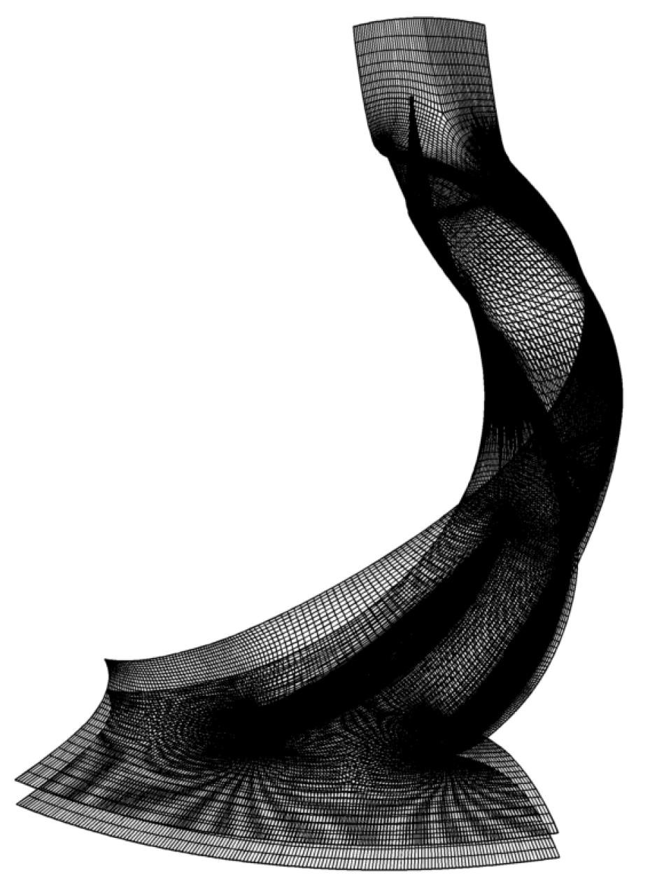
Figure 2 displays the grid partitioning diagram for the compressor in the FINE/Turbo16.1 software. The boundary conditions are appropriately set, assuming the working fluid to be an ideal gas. The inlet total pressure is set at 101.3 KPa, and the inlet total temperature is set to 288.15 K. The turbulent viscosity is 0.00005 m
2/s. The wall condition is defined as adiabatic with no slip, and the compressor operates at a rotational speed of 7 × 10
4 r/min in a rotating coordinate system. The convergence criterion for residual values is set to 10
−6. Different turbulence models have distinct thresholds for the y+ value. For the S-A model, the y+ value must be less than 10 to directly solve the viscous sublayer. To ensure precise capturing of the fluid state near the boundary, the first-layer mesh near the wall has a size of 0.005 mm with a y+ value of 5. Three grid models of varying coarseness, composed of 2,121,904, 1,881,016, and 1,526,405 grid cells, respectively, are selected to verify grid independence. The following quality requirements must be met: possess no negative cells, exhibit minimum orthogonality greater than 20°, demonstrate maximum expansion ratio less than 5, and display a maximum aspect ratio less than 1000. Finally, the pressure ratio and efficiency errors for different grid models are maintained within 0.3%. Grid coarseness exhibits minimal influence on the calculation results, as indicated in
Table 3.
According to the above simulation conditions for the flow field simulation of the compressor model, its maximum flow rate is 0.0561, the wheezing flow rate is 0.0233, the adiabatic efficiency is 0.828, and the pressure ratio is 1.46, so the performance of the compressor meets the design requirements.
By analyzing the internal flow field of the centrifugal compressor, the deficiencies in the performance of the compressor can be accurately explored so that the design of the compressor can be optimized.
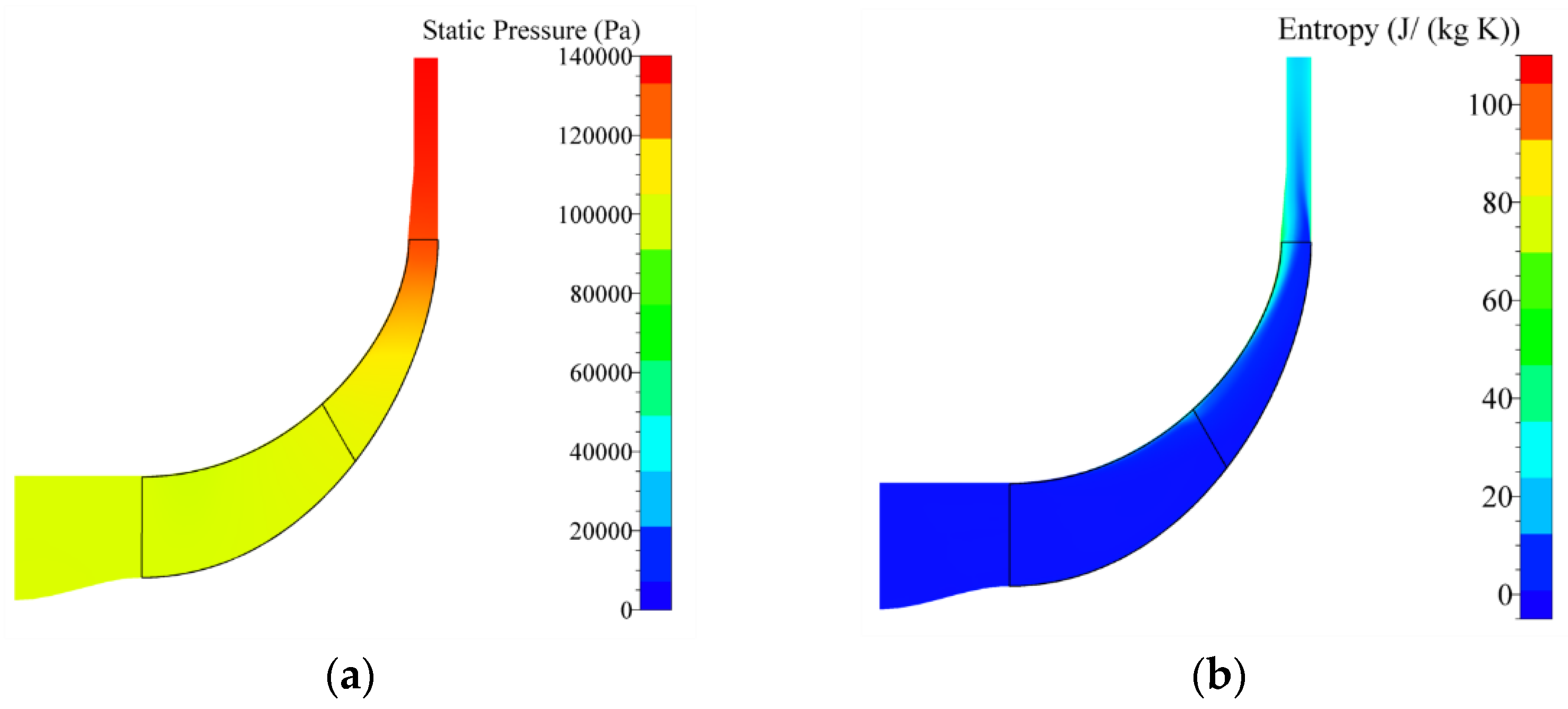
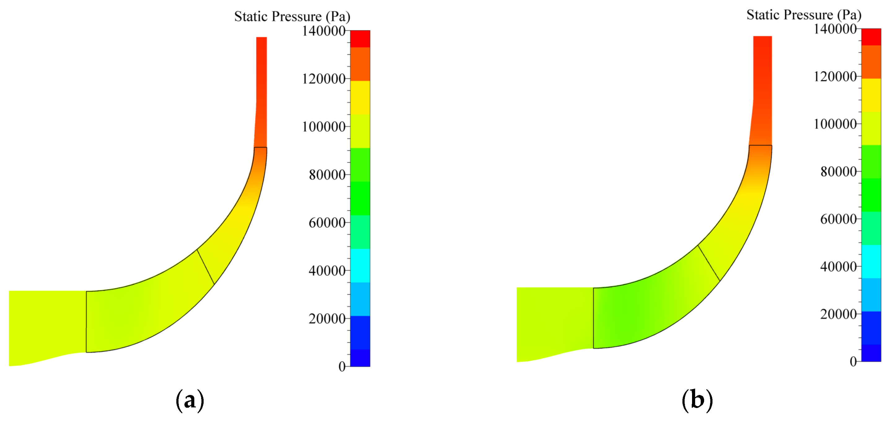
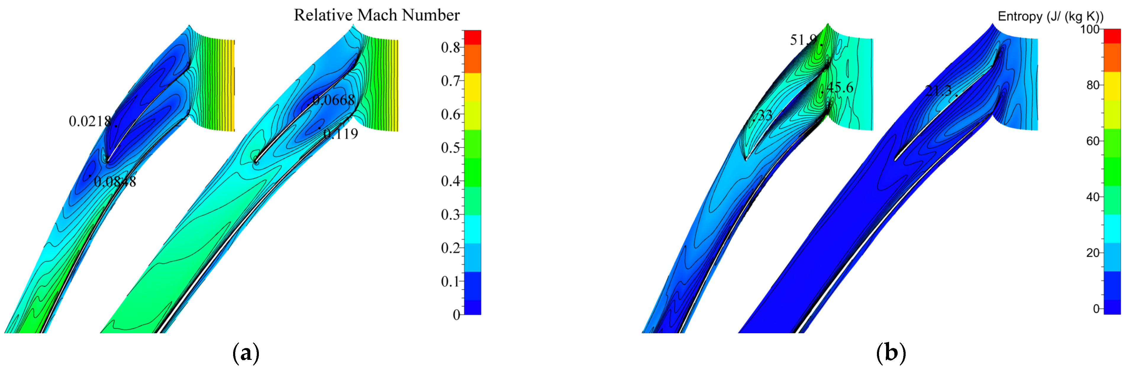
Figure 3a displays the impeller meridional surface static pressure diagram, where the gas converts kinetic energy into pressure energy by overcoming the adverse pressure gradient in the diffuser flow.
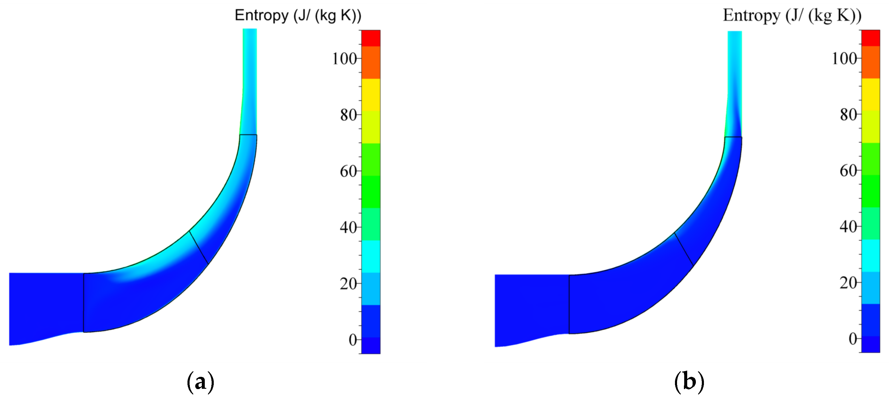
Figure 3b depicts the entropy increase of the meridional surface and highlights the tip clearance and bladeless diffuser as the primary regions of entropy gain. The tip clearance is mainly designed to prevent the collision between the compressor blade and the shroud. Due to the pressure difference between the blade suction and pressure surfaces, a portion of the fluid flows over the top of the blade, forming a leakage flow that leads to a loss of flow and an increase in the blade top entropy value. The bladeless diffuser has no blades, which eliminates impact loss. However, it incurs primary losses due to friction and separation loss. The separation occurs when the boundary layer lacks enough kinetic energy to convert pressure to overcome the adverse pressure gradient.
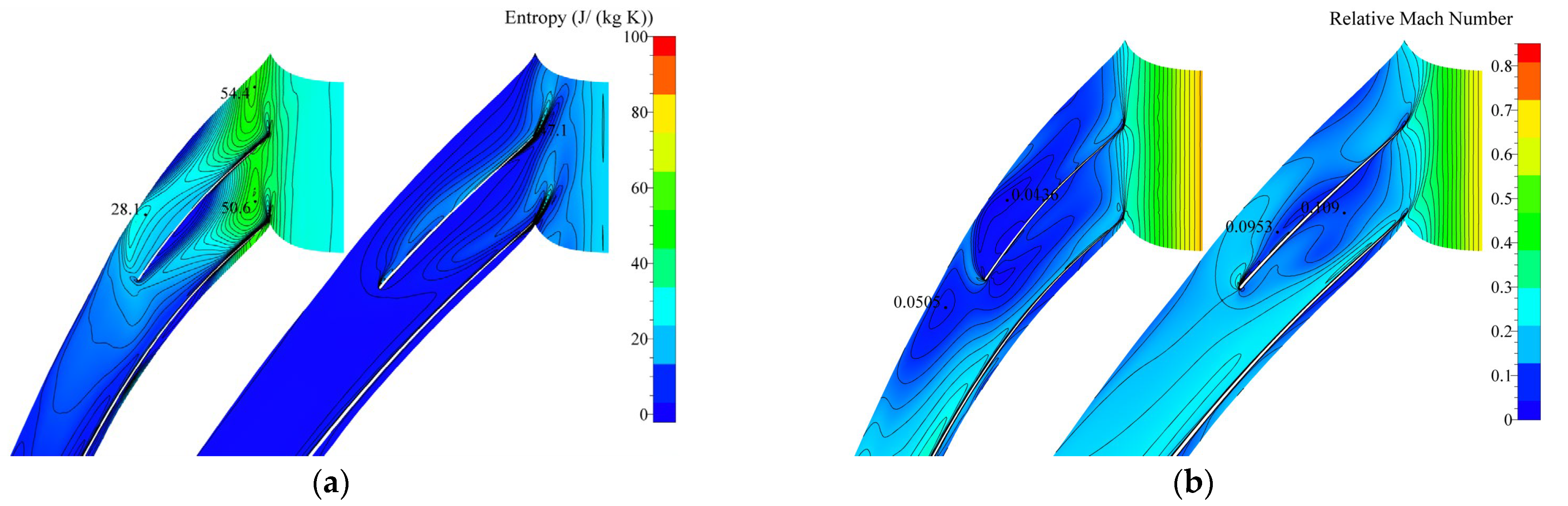
In
Figure 4a, the entropy distribution of the compressor is presented in the 95% and 50% blade height directions. The comparison between
Figure 4a and
Figure 3b shows that the larger entropy distribution is mainly observed on the suction surface of the main blade and splitter blade. This phenomenon is caused by the large hub turning angle where the airflow travels from the impeller inlet to the diffuser. During this process, the airflow needs to reduce its flow velocity and convert kinetic energy to pressure energy to overcome pressure gradients in the flow. However, a large pressure gradient results in a gradual decrease in flow velocity in both the main flow region and the boundary layer. The gas flow in the boundary layer, which has insufficient kinetic energy to overcome adverse pressure gradients, leads to stagnation, deceleration of gas, and the generation of large flow loss in the separation region. This results in reduced compressor efficiency.
Figure 4b shows two separation regions on the suction surface of the blade with low gas flow velocities, leading to significant flow loss, lower impeller efficiency, and lower pressure expansion capacity.
3. Study of the Influence of Relevant Parameters on the Performance of Centrifugal Compressors
Several factors influence the performance of a centrifugal compressor, including the compressor’s tip clearance, hub ratio, number of impeller blades, impeller inlet angle, circumferential position of the splitter blades, the impeller outlet width, and the backbend angle of the blades. This paper focuses on the main optimized parameters, namely, the number of impeller blades, the relative impeller outlet width, and the impeller backbend angle. By examining the effects of these parameters on the centrifugal compressor’s isentropic efficiency, pressure ratio, and flow rate, the impeller is optimized by selecting the parameter values that enhance the compressor’s performance. Ultimately, the optimized model is compared and analyzed with the preliminary model.
3.1. Number of Impeller Blades
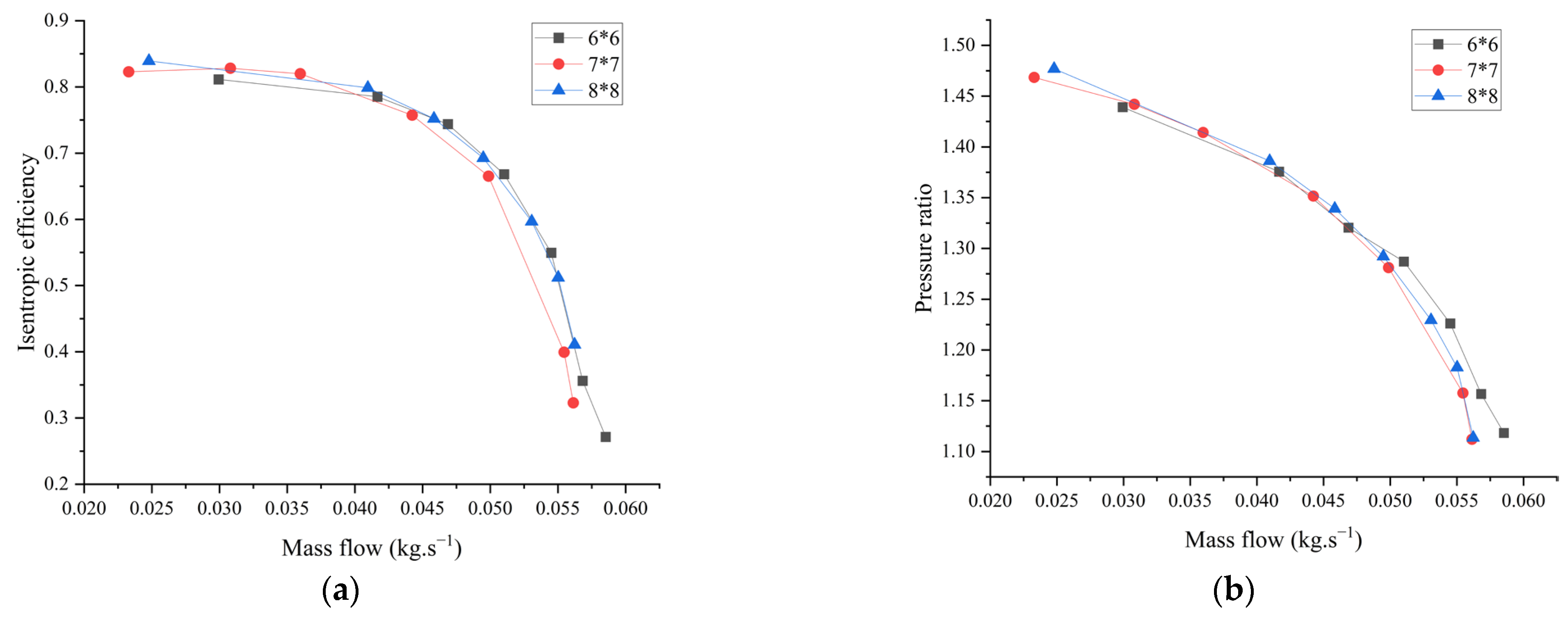
The centrifugal compressor’s impeller blades’ number has a significant impact, albeit not in a clear linear relationship. Therefore, specific analysis is necessary. This study used 7 × 7 blades in the initial model, and the number of blades was increased and decreased in subsequent models, choosing two groups with 6 × 6 and 8 × 8 blades, respectively.
Figure 5 illustrates the efficiency and pressure ratio as influenced by the impeller blades’ number. From the figure, it is evident that the compressor with 8 × 8 blades performs better than the others in the compressor’s working range, with an isentropic efficiency of up to 83% and a corresponding pressure ratio of 1.477.
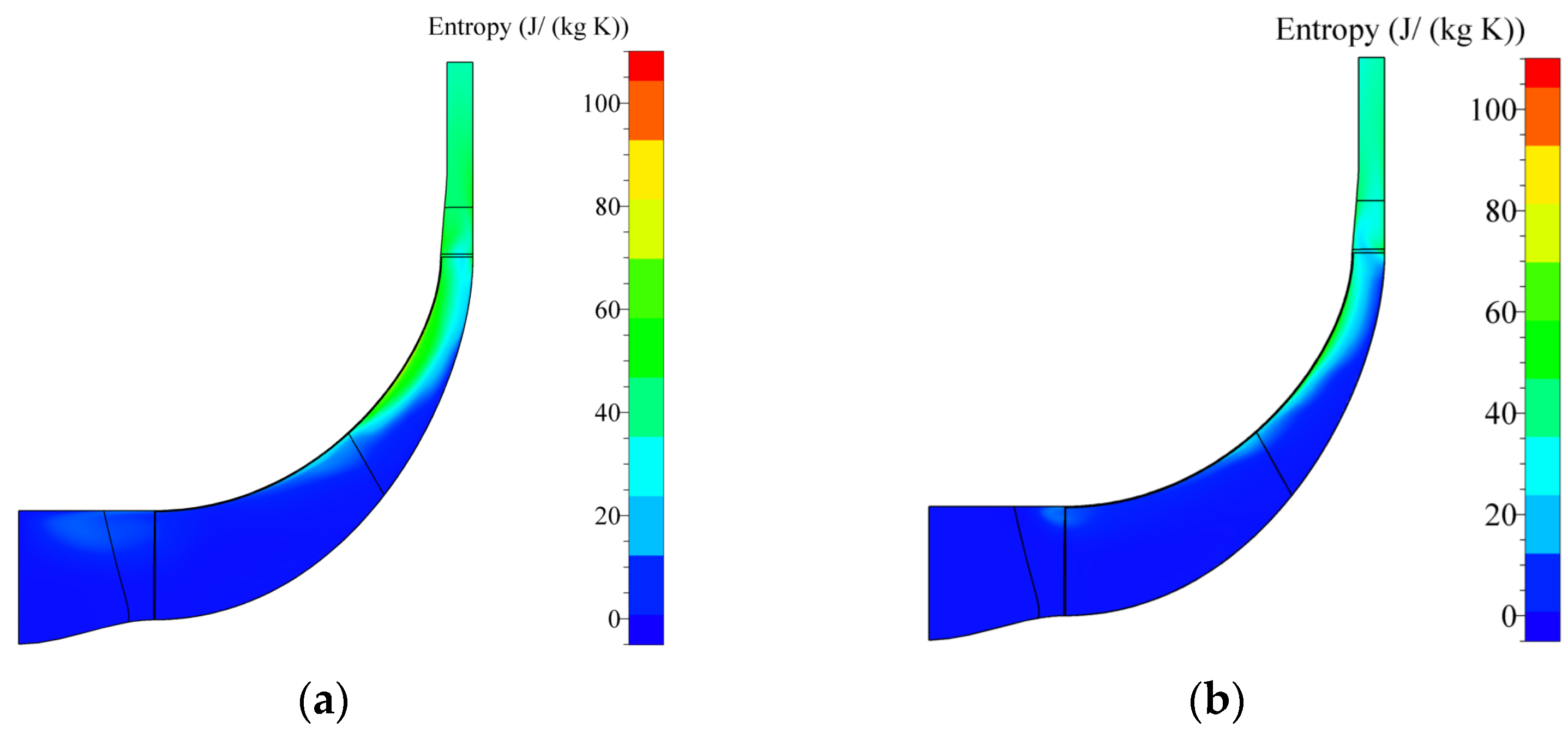
Figure 6 shows the distribution of entropy values at the impeller meridian surface for the 6 × 6 and 8 × 8 impeller blades when the compressor efficiency is highest. Comparing with
Figure 3b, it can be seen that, when the number of blades is 8 × 8, the entropy increasement at the tip clearance of the impeller is the smallest, and the energy loss of the compressor compared with the other two cases is reduced, which makes the efficiency of the compressor improved.
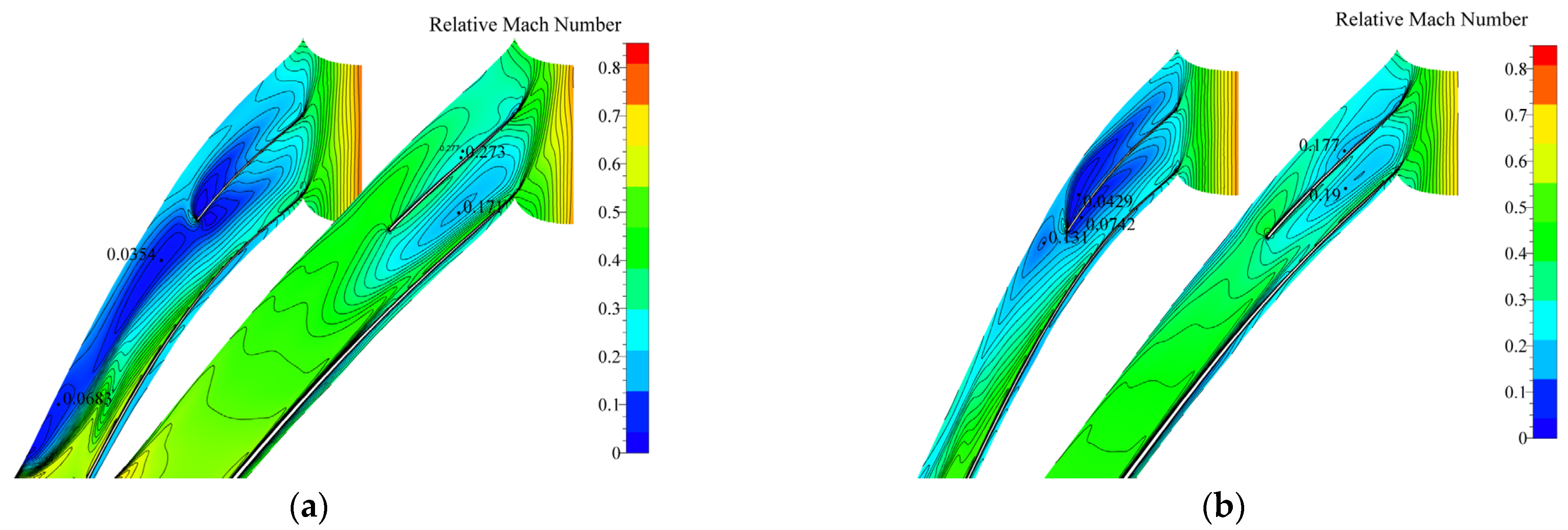
Figure 7 illustrates the relative Mach number distribution at 95% and 50% of the blade height under different blade numbers. Specifically, the relative Mach number of the 8 × 8 blade configuration is higher than that of 6 × 6 and 7 × 7 configurations. By examining
Figure 3b, it is clear that the impeller with the 6 × 6 blade configuration has a larger low-speed zone range than the impeller with the 7 × 7 configuration at the suction surface of the splitter blade at the 95% blade height direction. However, for the 8 × 8 blade configuration, the range of the low-speed zone is significantly reduced compared to the first two configurations, which indicates a decrease in separation loss. This decrease in separation loss is further supported by
Figure 8, which demonstrates that as the number of blades increases, the separation loss decreases. Thus, the 8 × 8 blade configuration has a significantly reduced entropy increasement region compared to the other two impellers. Finally,
Figure 5a shows an improvement in compressor efficiency for the 8 × 8 blade configuration.
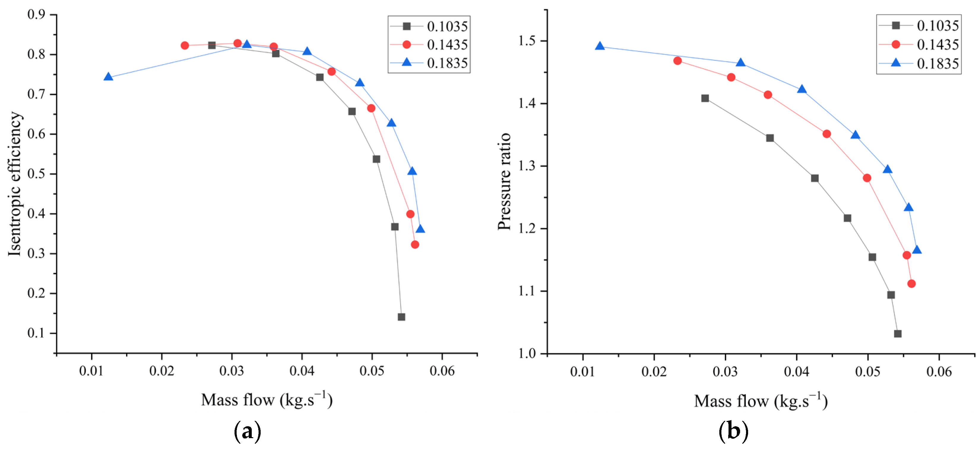
3.2. Impeller Outlet Relative Width
The impeller outlet relative width is defined as the ratio of impeller outlet width
d to impeller outlet diameter
D2. In this study, we set the initial impeller outlet width
d as 2.8173 mm and impeller outlet diameter
D2 as 19.627 mm, resulting in the initial impeller outlet relative width is 0.1435. By maintaining the impeller outlet radius, the impeller outlet width
d was altered to 3.601 mm and 2.0313 mm, resulting in relative outlet widths of 0.1835 and 0.1035, respectively. The simulation results of the compressor performance are shown in
Figure 9. An increase in the relative impeller outlet width corresponded to higher compressor efficiency and pressure ratio. The highest isentropic efficiency achieved was 0.81 when the relative outlet width was 0.1835. However, it should be noted that the isentropic efficiency is lower than that of the other two cases during low-flow conditions. On the other hand, the pressure ratio significantly improved when compared to the other two cases, as illustrated in
Figure 9.
Impeller relative outlet width change will affect the impeller outlet relative velocity and impeller outlet airflow direction. As the relative outlet width increases, the impeller outlet relative velocity decreases, while the pressure expansion degree increases.
Figure 10’s static pressure diagram of the compressor meridian surface highlights this relationship. Compared with
Figure 3a, it can be observed that an outlet width of 0.1835 results in the highest adverse pressure gradient on the impeller meridian surface. The high adverse pressure gradient reduces the relative flow velocity of the airflow in the diffuser, suppressing the radial flow of the vortex at the impeller’s trailing edge. As a result, the pressure expansion capacity is increased. Therefore, the pressure ratio will be higher than in the other two cases.
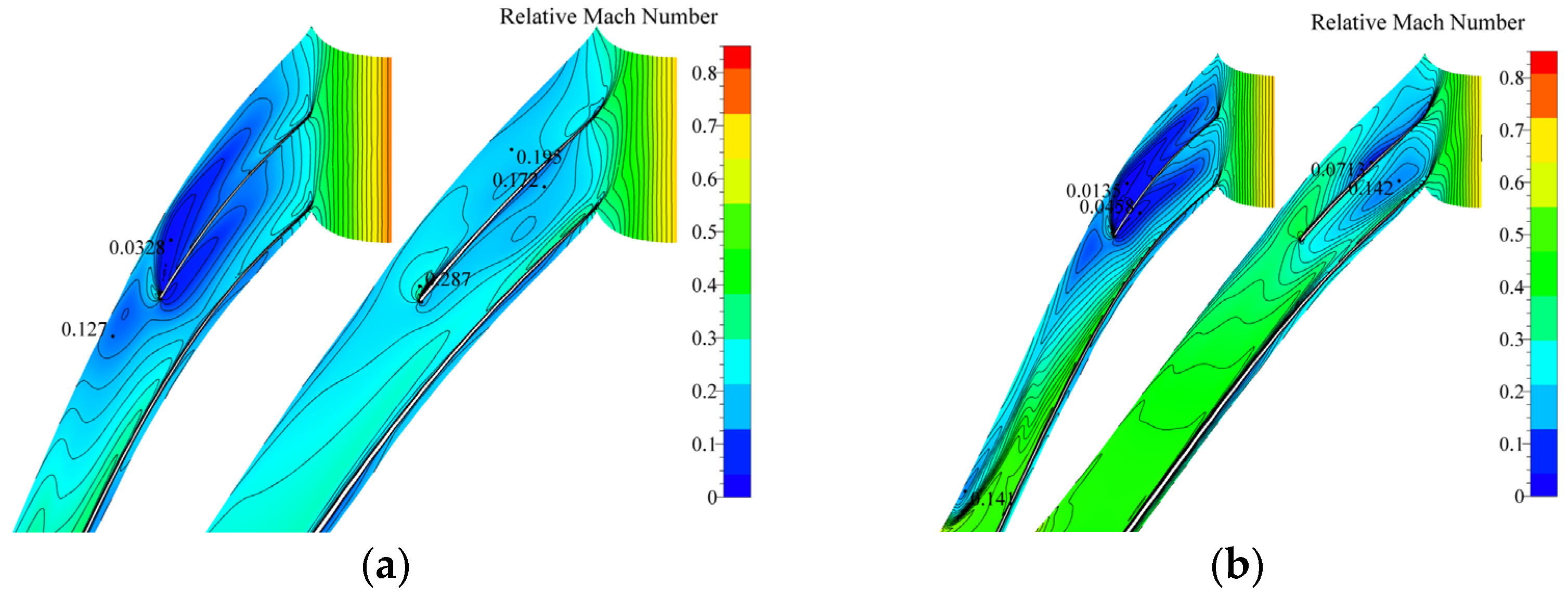
Figure 11 shows the relative Mach number distribution at the 95% and 50% blade heights of different impeller relative outlet widths. It can be observed that at both relative outlet widths, a lower relative Mach number region exists at the 95% blade height. The width of the impeller outlet affects the range of the low-speed zone, which is wider at the 0.1835 outlet width range than at the 0.1035 range with lower flow rate. At the 50% blade height, a low-speed zone is also present on the suction surface of the splitter blade, although not noticeably. The impeller’s outlet relative width affects the impeller’s inlet and outlet relative velocity ratio, which increases as the outlet relative width increases. This results in premature blade suction surface separation and increases separation loss, ultimately reducing efficiency. However, an adverse pressure gradient can improve the pressure expansion capacity. Therefore, in order to maintain efficiency at the design value, the relative outlet width of 0.1835 is recommended.
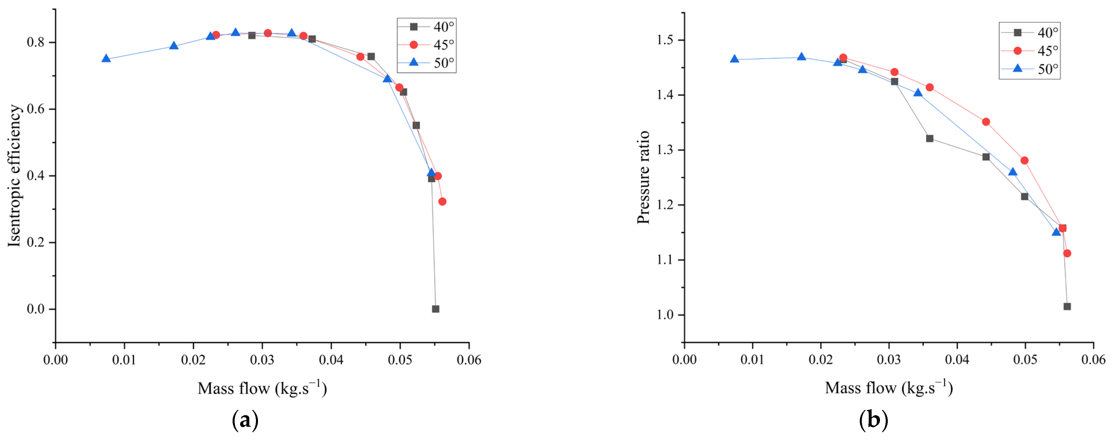
3.3. Blade Backbend Angle
The outlet backbend blade angle can be used to categorize impellers according to their orientation: forward impeller, backward impeller, or radial impeller. For this research, a backward impeller was used. Changing the blade backbend angle has an effect on the outlet airflow’s deflection angle, which consequently affects the compressor’s efficacy and pressure ratio. The initial blade backbend angle was set to 45°. The blade backbend angle was changed to 40° and 50°, and the impact on the compressor’s pressure ratio and efficacy were investigated. The findings of this study are presented in
Figure 12.
From
Figure 12b, it is evident that the pressure ratio of the impeller initially rises, then falls, as the blade backbend angle increases. The compressor’s pressure ratio is at its minimum when the blade backbend angle is 40°. An increase in the angle to 45° raises the pressure ratio, but as the impeller backbend angle advances, a decline in the pressure ratio is observed. Although the compressor efficiency remains relatively constant, the one with a blade backbend angle of 45° yields higher efficiency compared to the other two impellers.
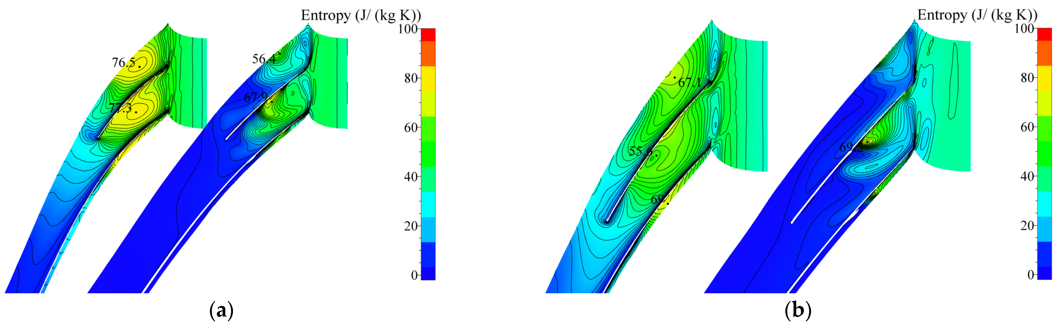
Figure 13 shows the entropy map of the impeller meridian surface for different blade backbend angles. The entropy value is observed to be higher for a blade backbend angle of 40° when compared to that of 50°. As depicted in
Figure 3b, a blade backbend angle of 45° results in the smallest meridian surface entropy value. Moreover, the regions with increased entropy values are primarily located at the tip clearance, blade trailing edge position, and diffuser internal.
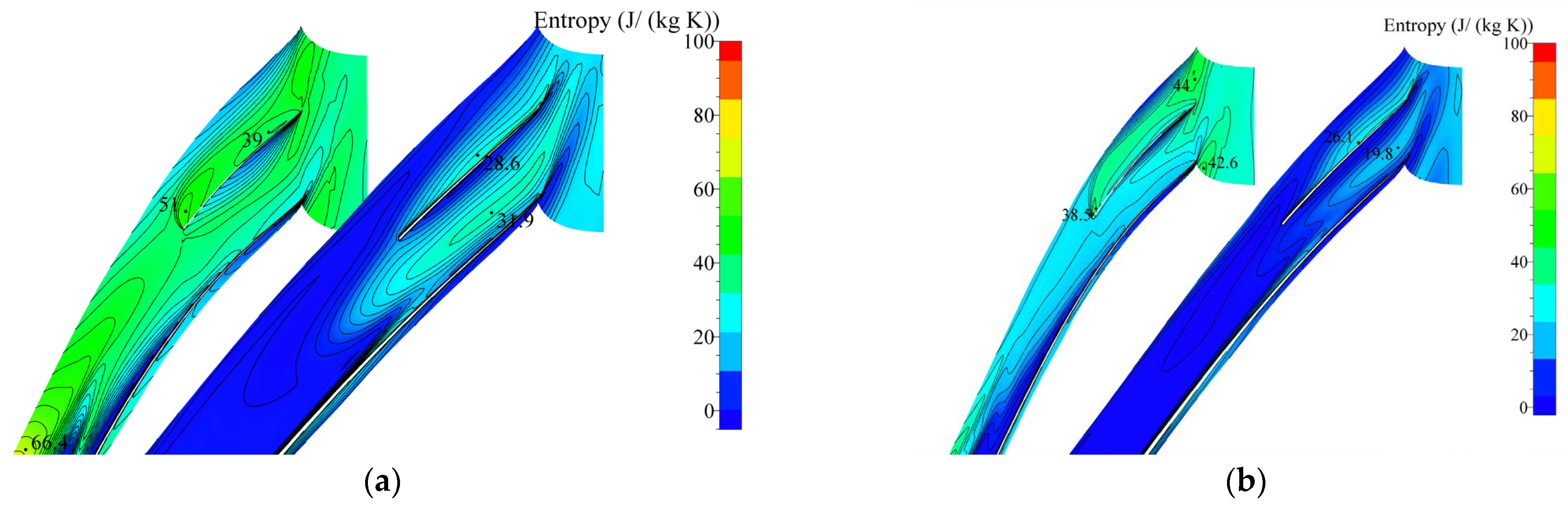
Figure 14 displays the entropy distribution at the 95% and 50% blade heights for different impeller backbend angles. A comparison with
Figure 4a indicates that for three different backbend angles of the impeller, both pressure surface entropy values in the main and splitter blades increase more at a backbend angle of 40° compared with the other two impellers. The entropy increase range for the splitter blade suction surface is also wider, leading to more serious gas mixing and, consequently, lower compressor efficiency and pressure ratio. While the impeller with a blade backbend angle of 45° experiences a significant decrease in entropy value at 95% of the blade height and an improved gas mixing phenomenon, the impeller with a backbend angle of 50° experiences a significant increase in entropy value due to the gas changing from axial to radial. This change induces a vortex area close to the compressor shroud, in which the velocity is reduced, and the energy loss increases. As the blade backbend angle increases, the outlet pressure of the compressor gradually decreases, leading to more airflow separation in the flow channel, increased energy loss, and decreased compressor efficiency. Therefore, the impeller with a backbend angle of 45° was selected for this study, to optimize its efficiency.
3.4. Design Parameter Optimization
According to the aforementioned study, optimization of parameters from the initial model had a significant impact on the compressor performance. The number of impeller blades was increased from the original 7 × 7 to 8 × 8 while retaining the backbend angle of the impeller at 45°. The relative outlet width was also increased to 0.1835, which adjusts the impeller outlet width to 3.601. All other parameters remained constant.
The optimized model is meshed, and
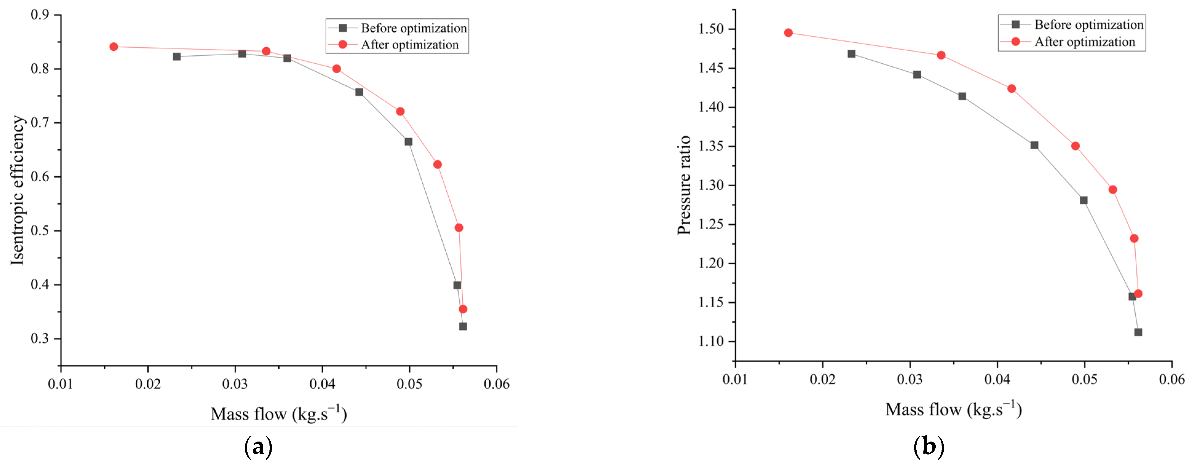
Figure 15 shows the performance curves of the compressor before and after optimization. The optimized efficiency and pressure ratio can reach 0.842 and 1.49, respectively, indicating a 1.4% and 1.8% improvement from their previous levels. Furthermore, the optimized isentropic efficiency and pressure ratio show higher readings at various flow rates compared to their previous values before optimization.
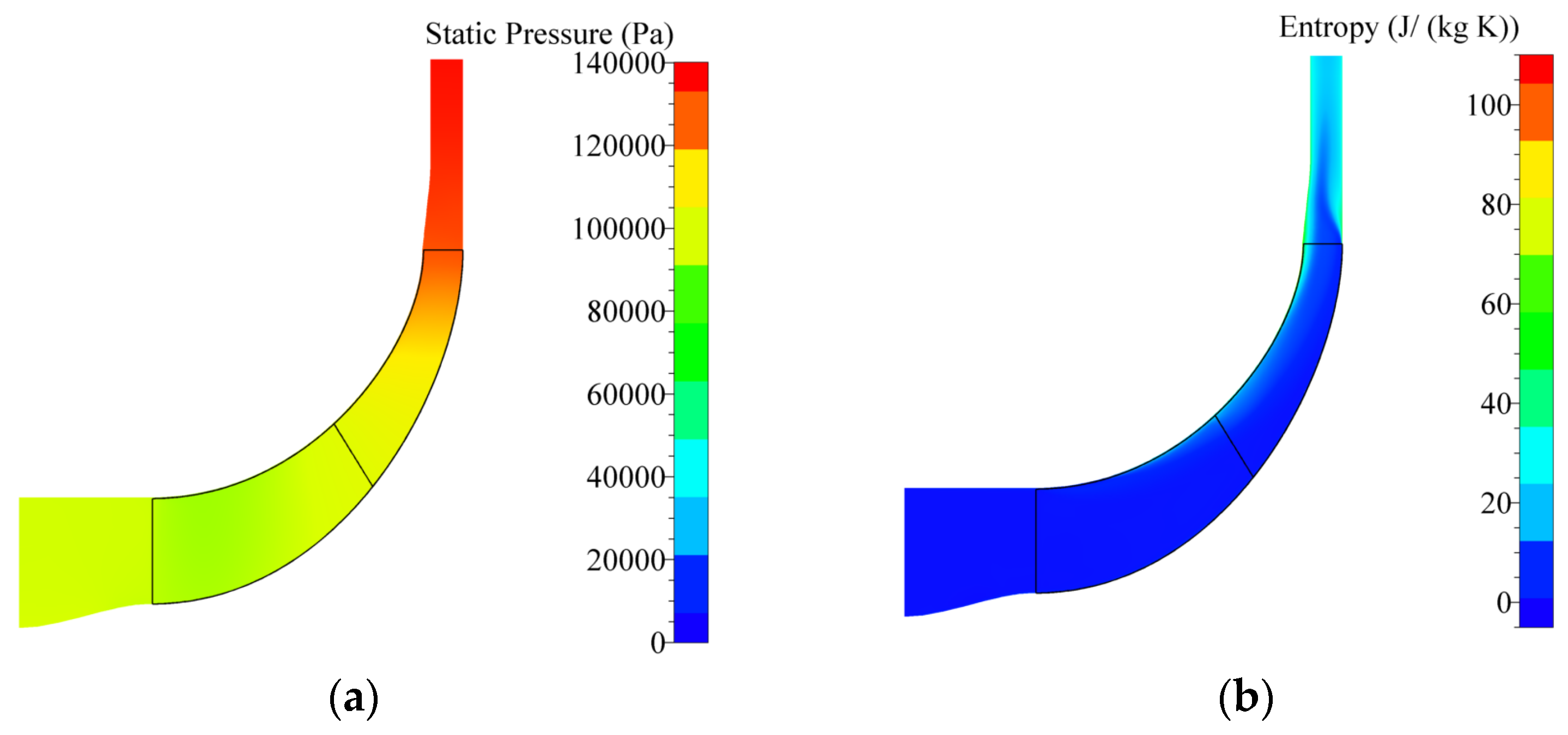
Figure 16a presents the optimized impeller meridian static pressure and entropy distribution diagrams. A comparison with
Figure 3 reveals that before optimization, the impeller meridian surface exhibits a small adverse pressure gradient. After optimization, the static pressure distribution is more even, characterized by a higher adverse pressure gradient, thereby lowering the relative flow velocity of airflow in the diffuser and improving the pressure expansion capacity. As
Figure 16b depicts, the entropy increase on the optimized impeller meridian surface is reduced by a considerable amount, indicating the mitigation of gas confusion in the tip clearance and bladeless diffuser section, and the improved uniformity of airflow in the bladeless diffuser section. This improvement enhances the compressor performance.
Figure 17a presents the relative Mach number distribution of the impeller at blade heights of 95% and 50%. The same low-speed region is shown in
Figure 4b. However, compared to before optimization, the range of the low-speed region is significantly reduced, and the speed is also increased. The main area of the impeller entropy gain in
Figure 17b overlaps with the low-speed region, where the presence of the low-speed region leads to the generation of separation loss. The entropy gain region is considerably smaller, and the entropy gain is significantly lower than before optimization. As a result of these changes, the efficiency and pressure ratio of the impeller are improved.
4. Experimentation
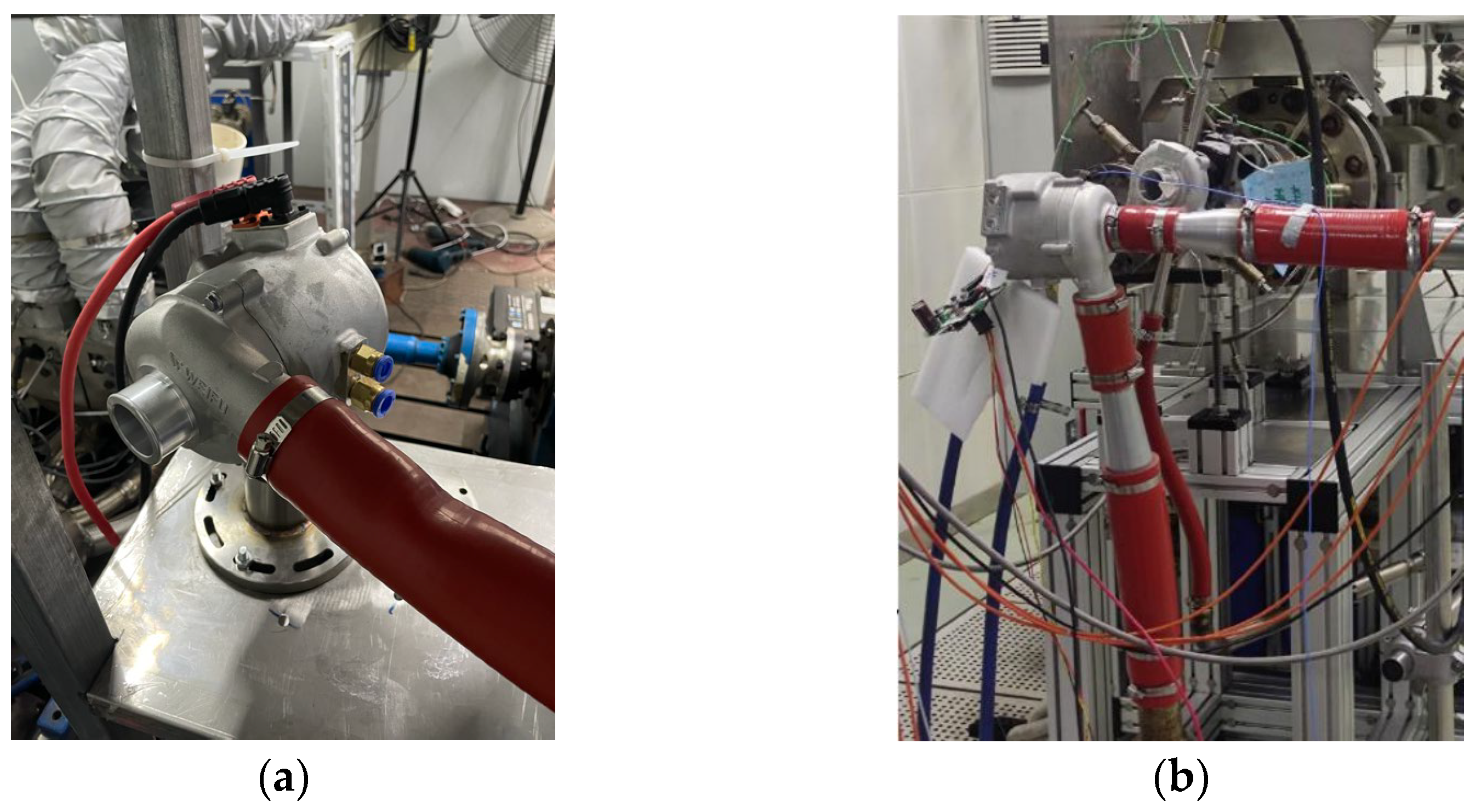
The experimental test bench consists of several key components: the INV9832-50 three-axis vibration acceleration sensor, an electric booster, an electronic control board, external water cooling, and tow atmospheric pressure sensors. The three-axis acceleration sensor is responsible for measuring speed variations in three dimensions, allowing for the monitoring of compressor vibrations during operation to ensure proper functionality. This sensor is capable of measuring within a range of 50 g, operates at temperatures between −50 °C and 120 °C, and has a maximum error of 0.05 g. The electronic control board functions primarily to manage compressor speed through a computer application program. This capability enables measurement of the compressor’s pressure ratio and efficiency at different speeds. To determine pressure changes, tow atmospheric pressure sensors are installed at both the inlet and outlet of the centrifugal compressor. This sensor records pressure fluctuations at different speeds, enabling the calculation of pressure ratio changes. The Honeywell HPB200F5DA atmospheric pressure sensor has a range of 500 to 1500 hPa, an operating temperature range of −40 °C to 110 °C, and an error range of ±0.4 hPa.
The physical model of the centrifugal compressor was developed based on the optimized impeller parameters, as shown in
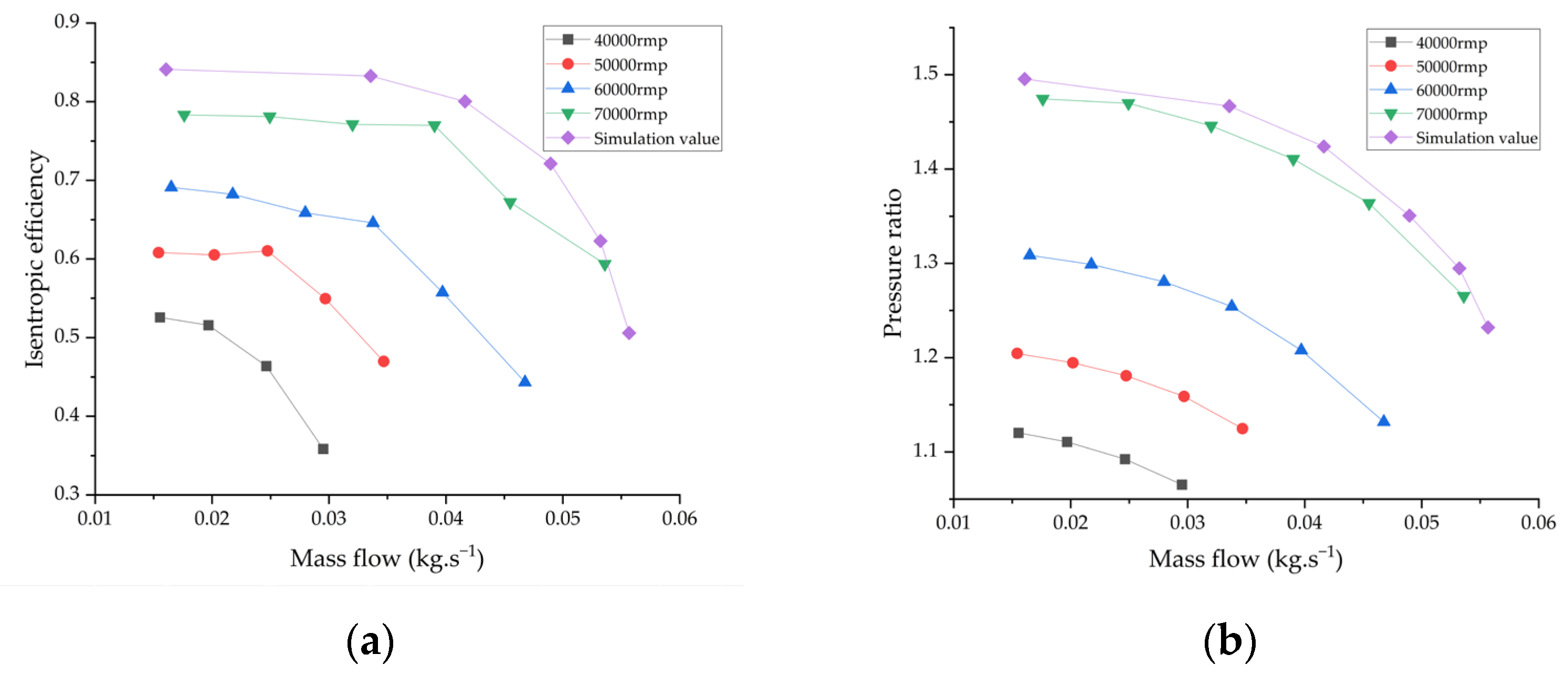
Figure 18a. The compressor’s efficiency and pressure ratio experiments were carried out on the bench with an ambient temperature of 25.61 °C and pressure of 103.03 KPa. The flow rate, pressure ratio, and efficiency of the compressor were evaluated at different RPM levels from 40,000–70,000 RPM, in steps of 10,000 RPM due to an insignificant boost effect of the electric supercharger at 10,000–30,000 RPM, as illustrated in
Figure 18b. Moreover, the overall vibration noise of the supercharger and the electric control board motor temperature was monitored. The experiment was conducted under the aforementioned experimental conditions, and the results are presented in
Figure 19. The experimental and simulated compressor performances were compared, indicating a minor difference within the acceptable error range. The compressor met the design requirements. To establish the overall credibility of the experiment,
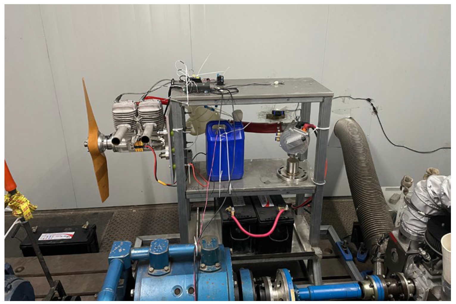
Figure 20 depicts the engine model equipped with a propeller, matching it with an electric booster, primarily utilized on unmanned aerial vehicles.


