Article

Influence of Blade Trailing-Edge Filing on the Transient Characteristics of the Centrifugal Pump during Startup

College of Mechanical and Electronic Engineering, Shandong University of Science and Technology, Qingdao 266590, China
*
Author to whom correspondence should be addressed.
Processes 2023, 11(8), 2420; https://doi.org/10.3390/pr11082420
Submission received: 13 June 2023 / Revised: 4 August 2023 / Accepted: 8 August 2023 / Published: 11 August 2023
(This article belongs to the Special Issue CFD Applications in Energy Engineering Research and Simulation)

Abstract

:
During the startup process of a centrifugal pump, the vibration and noise problems caused by unsteady flow are the focus of attention, and pressure pulsation is one of the main reasons for this problem. In the current research, a special impeller with blade pressure side trimming was proposed to reduce the strong pressure pulsation phenomenon during the startup process of centrifugal pumps. This article uses numerical simulation methods to simulate three typical blade trailing edges: original trailing edge (OTE), pressure side long linear (LLPS), and pressure side short linear (SLPS), and verifies them with experimental results. The results indicate that although the head of the centrifugal pump after filing has been reduced, its efficiency has been improved to a certain extent. Thirteen monitoring points were set up near the impeller outlet circumference and volute tongue to analyze the changes in pressure pulsation, verifying that blade trimming has a significant inhibitory effect on pressure pulsation during the startup of centrifugal pumps. The average maximum pressure pulsation amplitude of all monitoring points decreased by 32.23%, and the maximum pressure pulsation amplitude decreased by 56%. Blade trimming can affect the internal flow field distribution of centrifugal pumps. By analyzing the static pressure distribution, velocity streamline distribution, and vorticity distribution at the middle interface of three different impellers during startup, it was verified that there is a close relationship between pressure pulsation and unsteady flow structure during startup. The final conclusion is that blade trimming has a significant inhibitory effect on the pressure pulsation of the centrifugal pump during startup, and the impeller outlet vorticity is significantly reduced. The scheme proposed in this study has far-reaching prospects in the design of low noise centrifugal pumps.

1. Introduction

As a general fluid machinery, the centrifugal pump has been widely used in industrial and agricultural production [1]. Under normal working conditions, the centrifugal pump always maintains a stable state of operation. However, the pump will also encounter unstable conditions such as shutdown, variable speed adjustment, throttle adjustment, and speed fluctuation during operation, including at startup. In these cases, the flow characteristics of the centrifugal pump will change dramatically in a short time, resulting in strong vibration and noise, which will affect the safe operation of the pump and may cause damage to the pipeline and connecting equipment [2].
Considering the aforementioned circumstances, it becomes imperative to conduct an in-depth study on the transient characteristics of centrifugal pumps during startup to enhance their operational reliability. Tsukamoto et al. [3] first evaluated the transient characteristics of the pump by measuring the instantaneous speed, flow rate, and total pressure during the starting period. Duplaa et al. [4] established that low final flow rates usually enable the pump to reach low cavitating conditions at the end of startup, whereas increasing the final flow rate results in more developed cavitating conditions. Chalghoum et al. [5] analyzed the dynamic characteristics of pumps using the characteristic analysis method, revealing that the pressure evolution during startup is influenced by the valve opening percentage and starting time. Li et al. [6] established the transient performance test system of a centrifugal pump. The startup process of a centrifugal pump was tested, and PIV technology was used to analyze the test. Wang et al. [7] studied the transient behavior of an ultra-low specific speed centrifugal pump when it was stopped and started in the process of rapid depression lowering at the inlet and found that the rapid reduction of pump inlet pressure would accelerate the formation of cavitation. Li et al. [8] used a close-loop numerical model to realize unsteady self-coupled computations during the starting period and found that the transient vortex evolution between blades in the mean reason leading to the transient head coefficient was lower than the steady state value. Meng [9] also introduced a coupling simulation method for a closed-loop pipe system including a pump.
Zhou et al. [10] analyzed the circulating pipeline system and found that, during the startup process, the radial force and pulsation amplitude of the double volute were lower than those of the single volute. Zou et al. [11] studied the valve closing startup process of a large double-suction centrifugal pump and put forward the transient formula of radial force evolution in the startup process for the first time. Li et al. [12] designed an inlet elbow structure with a visible window for axial-flow pumps and observed an instantaneous impact head phenomenon in the final stage of centrifugal pump startup, affecting the impeller’s volume efficiency. Zhang et al. [13] analyzed that the difference between solid–liquid two-phase flow and pure water in the startup process is mainly reflected in the later stage. Zhang et al. [14] studied the startup of the pump by establishing a circulating pipeline system and found that the metastability flow calculation method was insufficient to predict the transient performance of the pump, especially in the early stage.
To reduce the vibration and noise generated during centrifugal pump startup, researchers have explored various blade structure design methods to minimize pressure pulsations. Dai [15] provided internal flow parameters for judging and predicting drag and noise reduction effects, and placed pits on the blade surface to reduce pressure pulsation and noise. Wang et al. [16] designed and optimized a bionic blade of equal thickness inspired by the C-shaped initial mid-arc of carp, and the unsteady interaction between blade wake and volute was significantly reduced, thus reducing noise. Kim et al. [17] found that under a small flow rate, the shape of the leading edge of the blade can be changed by increasing blade thickness to reduce eddy currents near the leading edge. Tao et al. [18] analyzed a semi-open centrifugal mud pump and obtained the blade trailing edge thickness with good wear characteristics and acceptable hydraulic loss. Based on the fluid-structure coupling method, Cui et al. [19] found that after cutting the trailing edge, the dominant frequency amplitude and low-frequency vibration displacement on the centrifugal pump impeller decreased. Qian et al. [20] utilized the NLPQL algorithm to optimize blade thickness, resulting in lower pressure pulsation intensity compared to the original impeller and similar performance to centrifugal pumps with shunt blades. Wu et al. [21] modified the pressure side profile of the blade to reduce the intensity of shedding vorticity at the trailing edge of the blade and the pressure pulsation in the volute. Furthermore, Wu et al. [22] redesigned the blade thickness of a five-blade centrifugal impeller based on force balance perpendicular to the streamline direction, effectively suppressing secondary flow development and improving energy efficiency.
Compared to the methods mentioned above, blade trailing edge filing is a straightforward and effective technique for mitigating operational vibration and noise in centrifugal pumps. Ryi et al. [23] found that a traditional sawtooth trailing edge has a better noise reduction effect on wind turbine rotors than an inclined sawtooth trailing edge. Gao et al. [24] studied the influence of five blade trailing edge shapes on the performance and pressure pulsation of low specific speed centrifugal pumps. The results showed that EPS (ellipse on pressure side) and EBS (ellipse on both sides) can both reduce the eddy current intensity at the trailing edge of the blade, significantly improve the efficiency of the pump, and reduce the pressure pulsation. Huang et al. [25] found that filing the trailing edge of the blade reduces the outlet angle of the blade, leading to an increase in head and a decrease in pressure pulsation.
In summary, blade trailing edge filing is a method suitable for practical engineering, but its impact on centrifugal pump startup is not clear, and research results are relatively limited. The article analyzes the internal flow field of a low specific speed centrifugal pump. To achieve this, A full channel model of three different trailing edge impellers of a centrifugal pump was established using 3D design software. Subsequently, both steady-state and unsteady simulations were conducted on the model by utilizing CFX 19.2 software. This paper analyzes the relationship between pressure distribution, velocity streamline distribution, vorticity distribution, and pressure pulsation phenomenon of centrifugal pumps with different blade trailing edges during startup, providing a reference for the vibration reduction of centrifugal pumps during startup. The main layout of this article is as follows: Section 2 introduces the pump model and grid division and describes the solver settings and experimental verification methods, Section 3 discusses the external and internal flow characteristics of the pump, and Section 4 presents the conclusions discussed above.

2. Numerical Setup

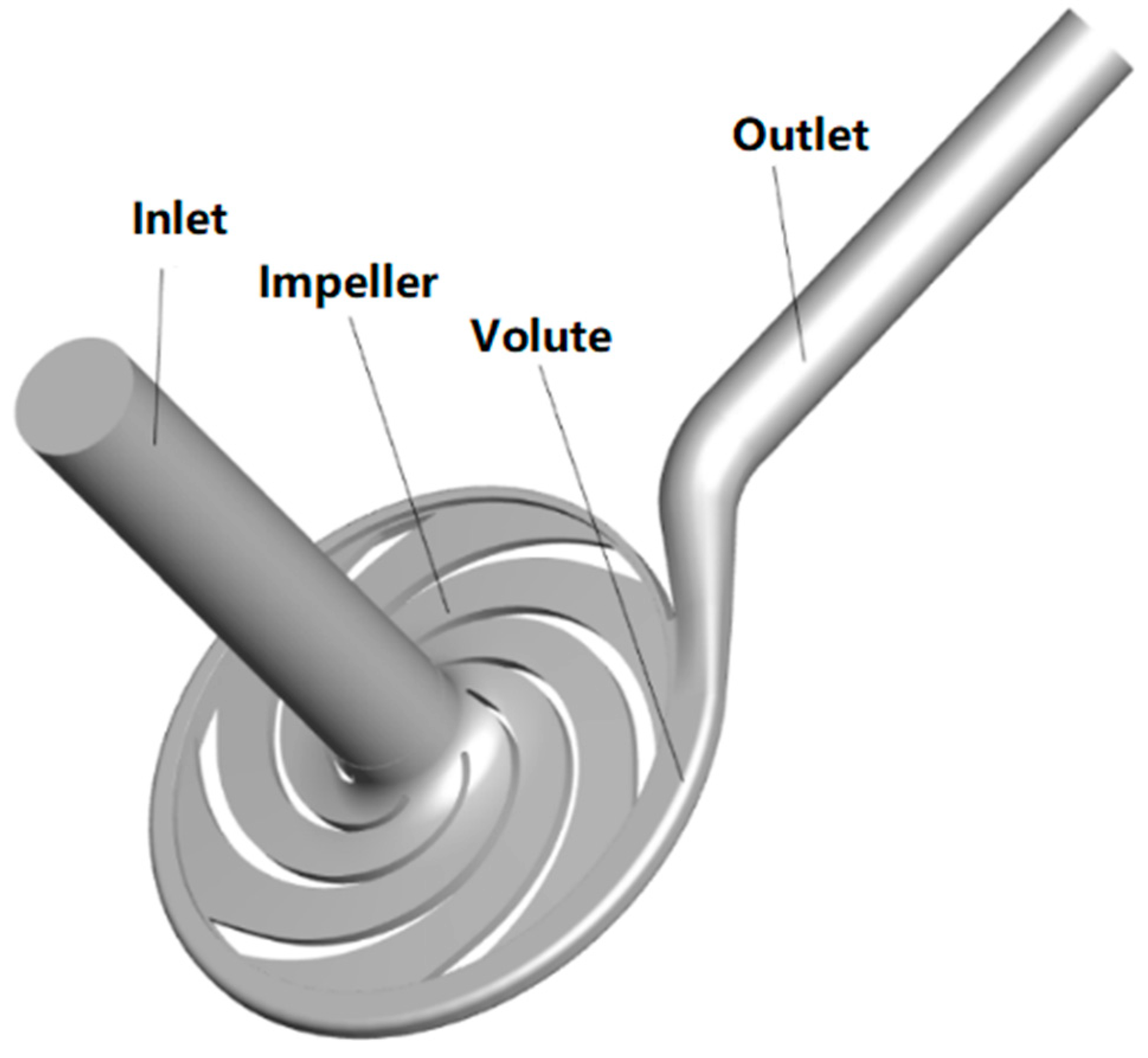
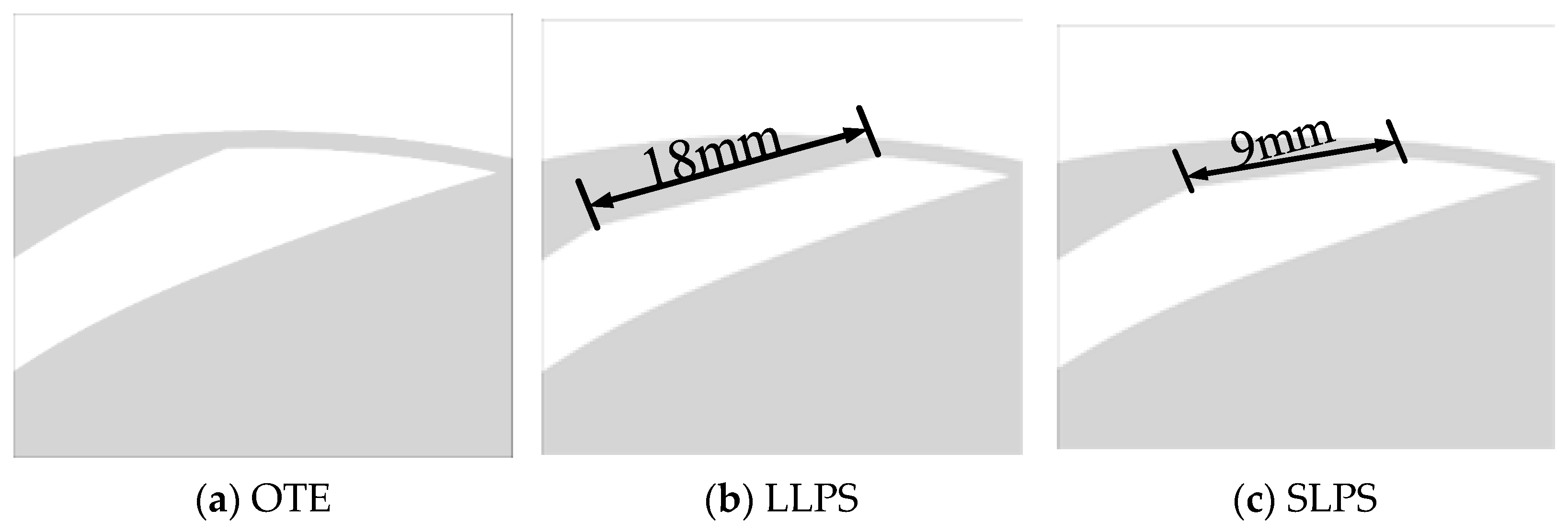
2.1. Computational Domain

The model pump designed in this paper is a low specific speed centrifugal pump with n s = 33 . The rated flow rate is 12.5 m3h−1 and the head is 50 m. In order to ensure the flow stability and accuracy during the simulation and avoid the backflow phenomenon, a reasonable extension is carried out at the impeller inlet and volute outlet.
For the CFD simulation, the computational domain includes inlet, impeller, volute, and outlet. Figure 1 shows the 3D geometry model of each component, and the specific parameters of the centrifugal pump model are shown in Table 1.
Due to the thickness of the pump blade, the fluid velocity and pressure in the wake area of the blade outlet are different from the mainstream, which will cause flow loss and reduce efficiency. However, changing the blade thickness and adjusting the blade outlet angle by trimming the blade trailing edge can reduce the shedding vortex, reduce the dynamic and static interference between the impeller and the tongue, reduce the wake loss at the blade outlet, and improve the non-uniformity of fluid flow direction and velocity distribution.
By filing the trailing edge of the impeller blade, the problem that the performance parameters of the centrifugal pump in engineering do not meet the requirements of field use can be solved. Because the performance of the pump can be improved by changing less geometric parameters, the vibration of the pump system can be reduced and the cost of impeller modification can be reduced. Therefore, it is necessary to study the blade trailing edge filing.
Under the condition of keeping the main structural parameters in Table 1 unchanged, the pressure side of the centrifugal pump blade was filed, and the pressure side was linearly filed with two lengths, respectively. The trailing edge of the blade after filing is shown in Figure 2. Among them, the prototype centrifugal pump is recorded as OTE and the file pressure side thickness is all blade outlet circumference length (18 mm) and half blade outlet circumference length (9 mm) recorded, respectively, as LLPS and SLPS. The blade filing is retained at least 2 mm in the circumferential direction to ensure the impeller blade structural strength.

2.2. Meshes

The fluid domain of the centrifugal pump that needs to be calculated includes impeller, volute, inlet extension section, and outlet extension section. The calculation domain adopts a hexahedral grid; Figure 3 is the final mesh details used for the centrifugal pump. In order to improve the mesh quality and calculation accuracy of the computational domain, the mesh refinement is carried out in the regions with large curvature, such as blade, tongue, and impeller outlet, and the boundary layer is divided. The first layer has a thickness of 0.005 mm and a growth rate of 1.2. The mesh quality of all computational regions is above 0.5. ANSYS-ICEM-CFD 19.2 software was used to build the structured meshes associated with the block topology of Y-type and O-type, and appropriate mesh density was decided according to the gird independence test.
Aiming at the external characteristics of the pump, the interference of grid size is eliminated, and the grid independence verification results shown in Table 2 are obtained. Taking the head and efficiency of Test case 3 as the standard, when the number of grids is more than 3.6 million, increase the number of grids, and the change of head and efficiency of simulation is very small. The relative scatter is very small and the workload is greatly reduced, which further verifies the accuracy of the CFD calculation results. As long as it does not affect the predicted values of water head and mechanical power, the possible errors in calculating the flow field are acceptable [26]. Finally, it can be determined that the number of grids in impeller, volute, inlet section, and outlet section are 1,730,000, 990,000, 570,000, and 430,000, respectively, and the total number of grids is 3.6 million.

2.3. Numerical Settings

ANSYS CFX 19.2 software was used to run the steady state calculation and transient calculation of the centrifugal pump startup process for this study, in which the SST k-ω turbulence model and the SIMPLEC algorithm was used to solve the discrete difference equations of the second-order upwind scheme. By controlling the change of rotational speed, n , to simulate the starting state of the centrifugal pump, centrifugal pump instantaneous speed, n , is defined as follows:
n = n max e t t 0
where n max is the rated speed of the centrifugal pump, t is the instantaneous time, and t 0 is rated acceleration time; in this paper, t 0 = 0.15 s.
The inlet boundary condition is set to Total Pressure (stable), which is set to 1 atm. The outlet boundary condition is set to Mass Flow Rate and the outlet flow is set to Q; Q can be obtained by the relationship between flow and speed through the similarity law. The instantaneous flow of the centrifugal pump, Q, is defined as follows:
Q = Q 0 n n max
where Q 0 is the rated flow rate of the centrifugal pump.
In the setting of transient numerical calculation, the turbulence intensity is set to be medium (Intensity = 5%), each surface of the impeller is set to a rotating wall, and the roughness of the wall is set to a smooth wall. The interface between the rotating area and the static area of the impeller is set to transient Rotor Stator, and the grid connection mode is set to GGI. The computational time interval was set to 0.0000556 s in the unsteady computations, so the impeller will rotate 1° in a time step; the convergence criterion was 10−4 in the simulation at all working conditions, and the number of internal cycles is set to 10.
When focusing on the pressure pulsation characteristics in some important regions of the centrifugal pump, some monitoring points are mounted on the mid-span plane of the centrifugal pump, as illustrated in Figure 4. Thirteen monitoring points (P0–P12) are evenly mounted on the diffuser outlet with an angle of 30°.

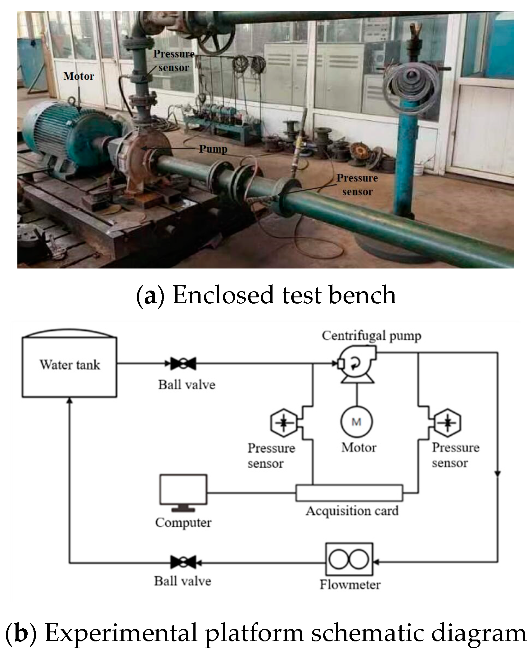
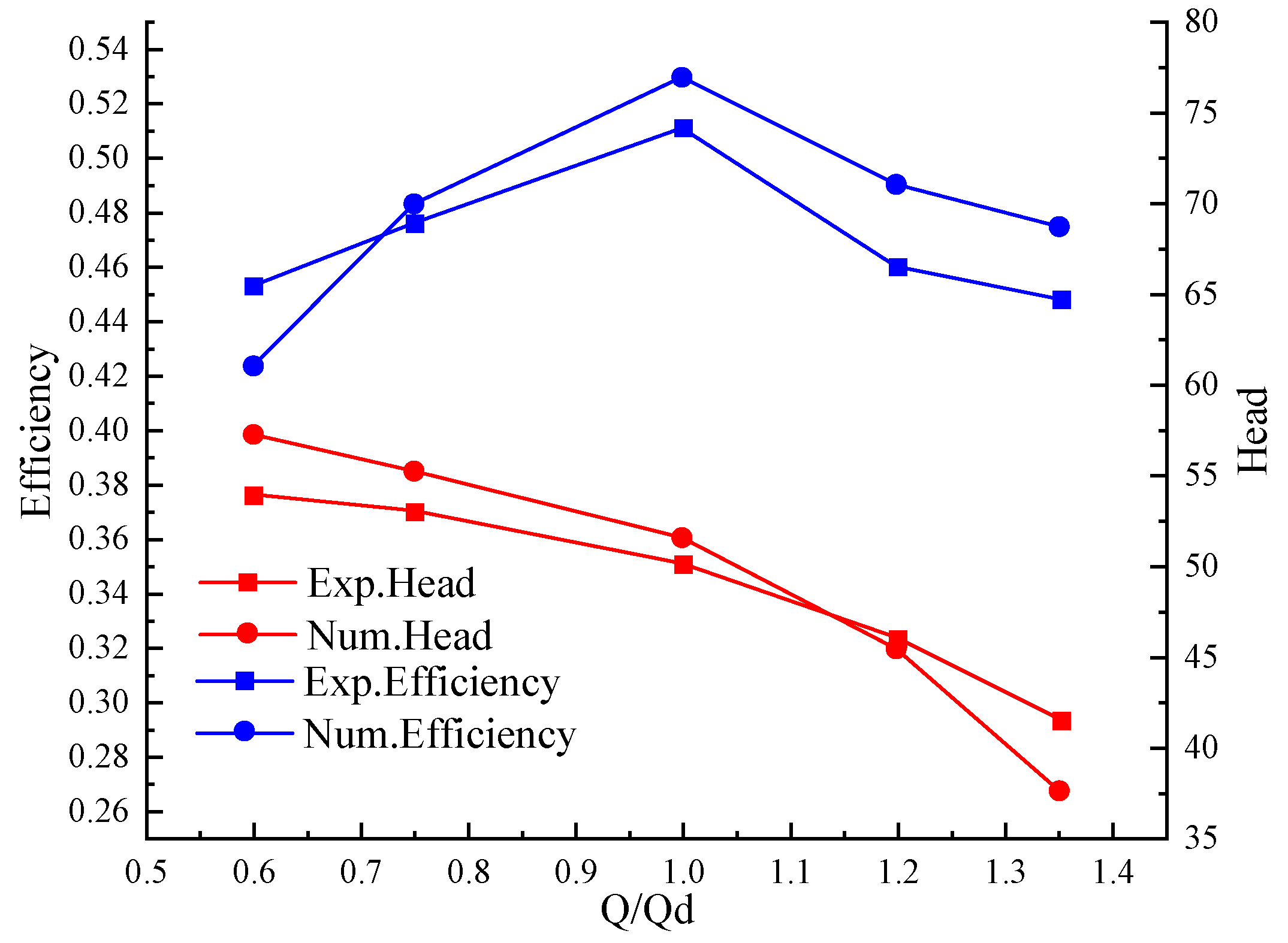
2.4. Experimental Verification

As shown in Figure 5a, a closed experimental platform is established to verify the accuracy of the numerical simulation. The system includes valve, water tank, pressure sensor, data acquisition card, electromagnetic flowmeter, and centrifugal pump with the same model as the model pump. The measurement range of the electromagnetic flowmeter is 0.87 m3h−1~43.42 m3h−1, and its accuracy is less than 0.5% of the measured value. Two identical pressure sensors are installed on the inlet and outlet pipes of the pump, with a measurement range of −1~5 bar (accuracy ± 0.5%). In order to measure the power, the actual output power of the no-load test motor can be obtained by the loss analysis method, and the rotational speed of the centrifugal pump can be measured by a photoelectric tachometer. Figure 5b shows the layout of the experimental platform.
The methodology was as follows: Check the connection status of the centrifugal pump pipeline before the test and fill the pump with water. Run the centrifugal pump at low speed for 3 min with the outlet valve closed, and then open the outlet valve to run at the design flow for 20 min to check whether the platform is normal. If the system is normal, carry out 5 flow point tests from small flow to large flow. After the centrifugal pump runs for five minutes at each flow point, collect data every other minute for a total of 9 times, and then close the test bench.
The comprehensive uncertainty of the pump under five working conditions is calculated, and the comprehensive uncertainty is not more than ±1%. The measurement accuracy of each parameter meets the standard.
Figure 6 shows the comparison between the measured experimental performance curve and the numerical head of the OTE pump, which verifies the calculation accuracy of the numerical model adopted. For all relevant flow conditions, we note that the predicted head agrees well with the experimentally measured head curve. At nominal flow rate, the difference in head rise coefficient between the datasheet curve and numerical results is approximately 0.0374 and the average relative error of efficiency is 4.76%, both of which are less than 5%. Therefore, the calculation model is more accurate in predicting the external characteristics of the centrifugal pump, which verifies the validity of the numerical calculation method.

3. Results and Discussion

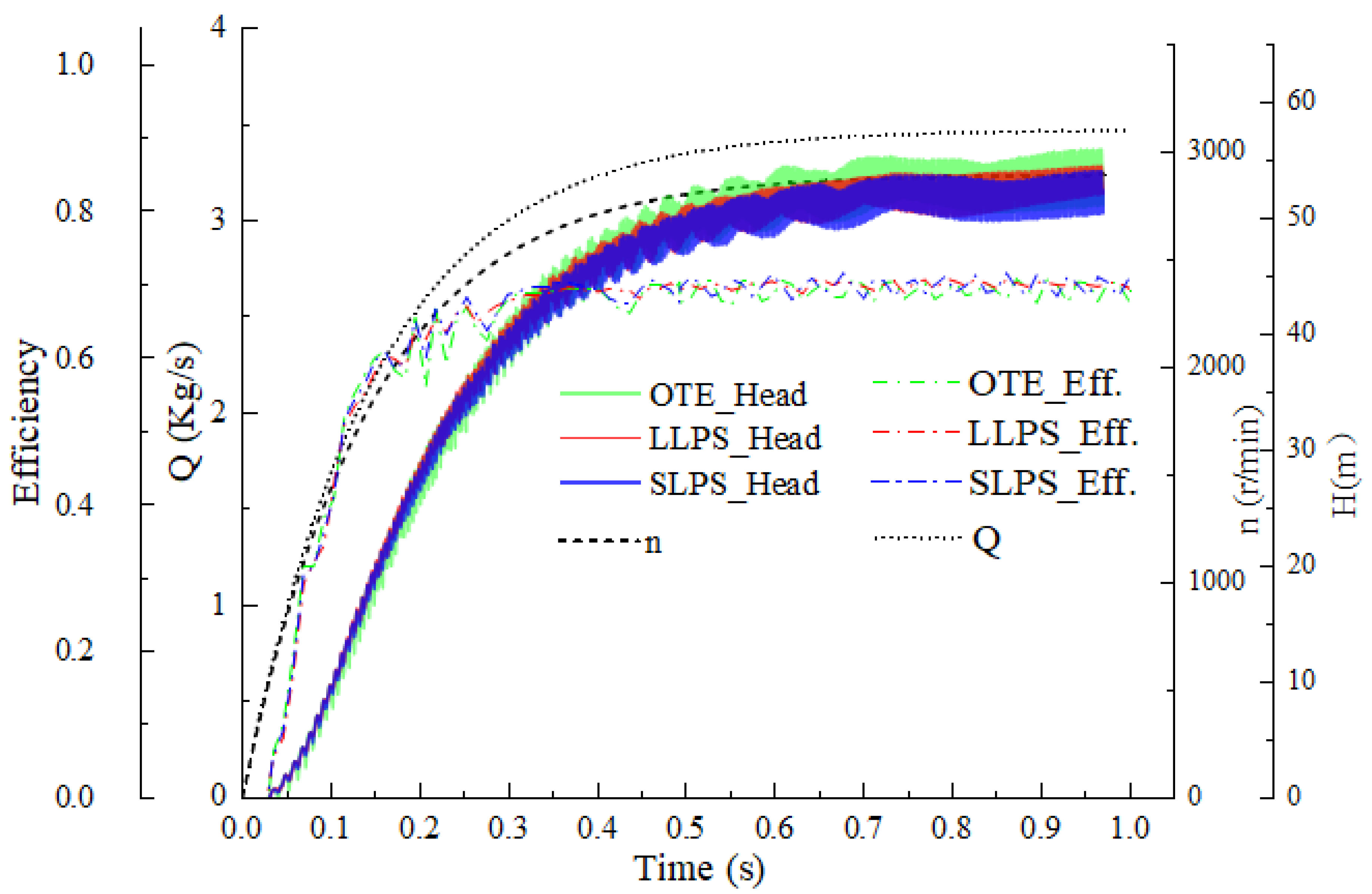
3.1. External Characteristic Analysis

The external characteristic curves of centrifugal pumps with different blade trailing edges during startup are shown in Figure 7.
It can be seen from Figure 7 that the head and efficiency of the centrifugal pump show a fluctuating upward trend during the startup process, and the curves of the LLPS or SLPS are delayed, and the delay time is 0.0322 s. The reason may be that there is no effective flow field in the centrifugal pump at the initial startup stage, and there is no ability to pump the fluid, resulting in the head and efficiency being 0 before 0.0322 s. It can be seen from the efficiency–time curve that the curve becomes stable at 0.3 s. At 0.2~0.3 s, the efficiency fluctuates obviously and reaches a stable state quickly after the pulsation. It can be clearly seen that the average efficiency of OTE after stability is 69.05%, and the average efficiency of LLPS and SLPS is 69.68% and 69.63%, respectively, indicating that the cutting of the trailing edge of the pressure side blade can improve the efficiency of the centrifugal pump to a certain extent. This may be because the trailing edge filing prevents the separation of the boundary layer, thus reducing the friction and separation loss.
The centrifugal pump speed tends to be stable after 0.5 s, and the flow rate change is not obvious. Fast Fourier transform (FFT) was performed on the heads of three centrifugal pumps with different blade trailing edge filings after 0.5 s, and the frequency spectrum of the head in the starting process was obtained. Figure 8 shows that the change trend of the head of centrifugal pumps with different blade trailing edge filings is basically the same, but the head amplitude of the OTE pump is larger than that of the LLPS pump and SLPS pump. The head amplitudes of the OTE pump, LLPS pump, and SLPS pump are 1.58 m, 1.26 m, and 1.12 m, respectively. The head amplitude of the LLPS pump decreases by 29%, and the head amplitude of the SLPS pump decreases by 20%. Thus, the blade pressure side filing can effectively reduce the amplitude of the head, and the effect of the LLPS pump is better. It can be seen from the diagram that the main frequency of each type of centrifugal pump is 76.1411 Hz, which is 1.5 times the rotating frequency of the centrifugal pump.

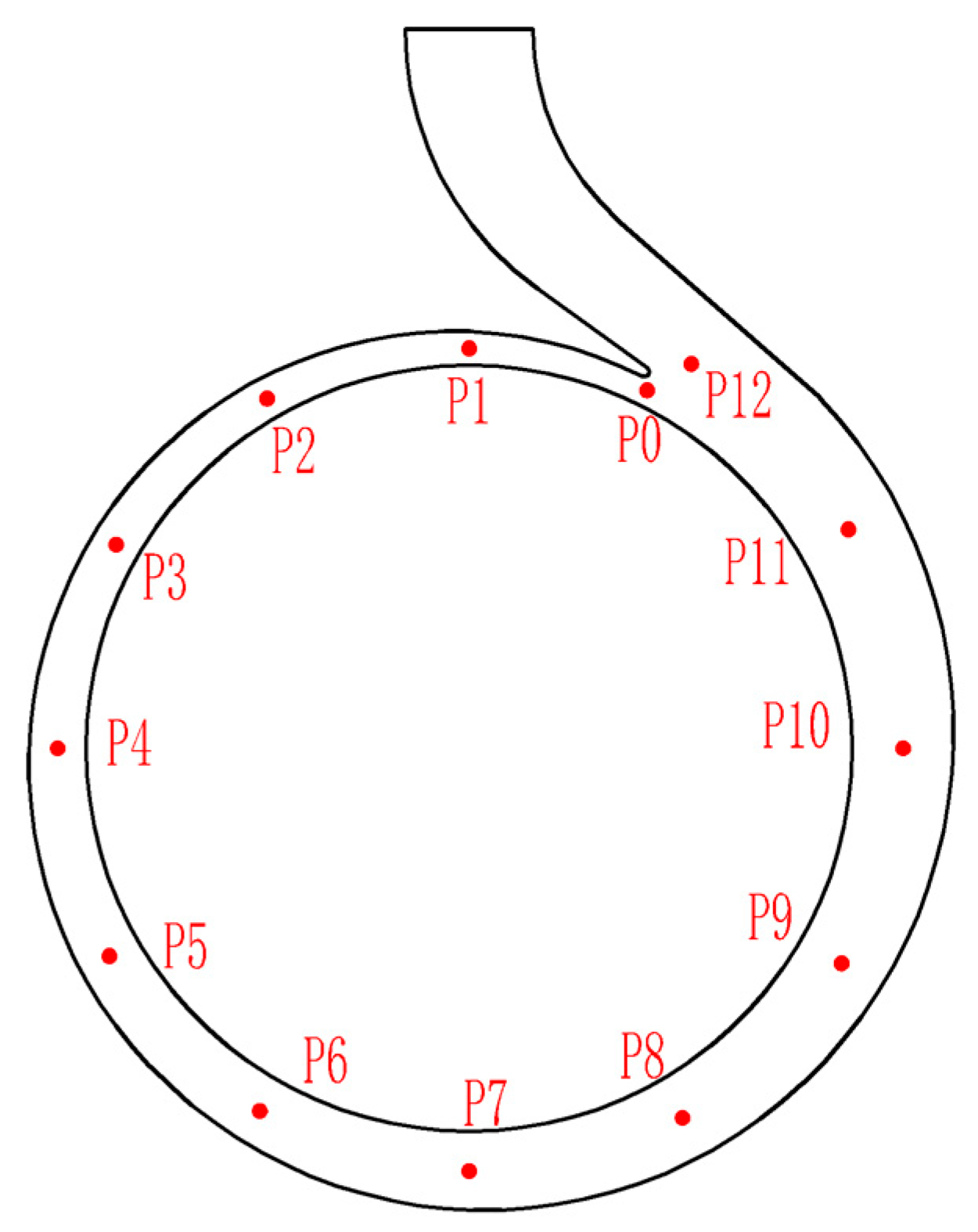
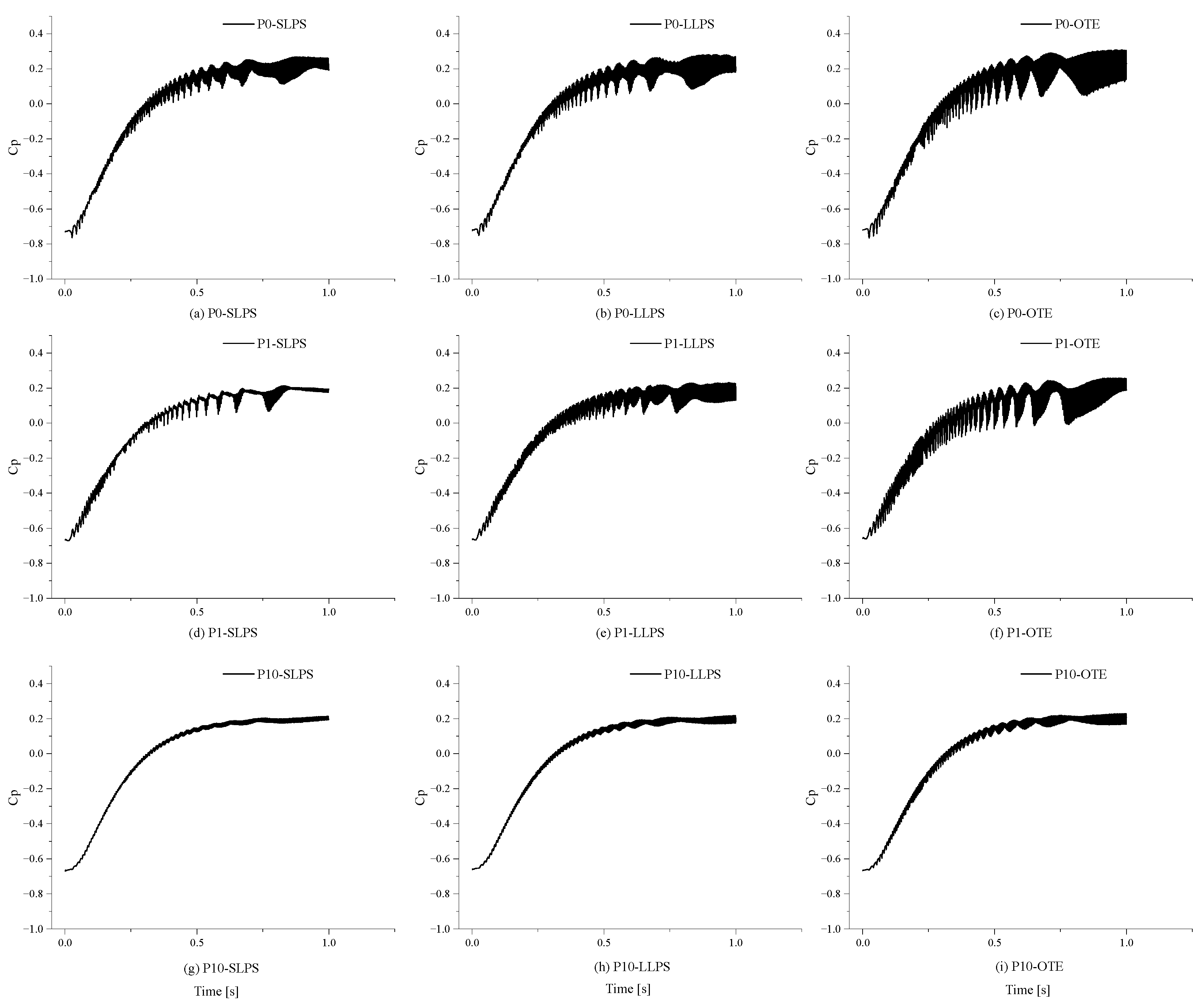
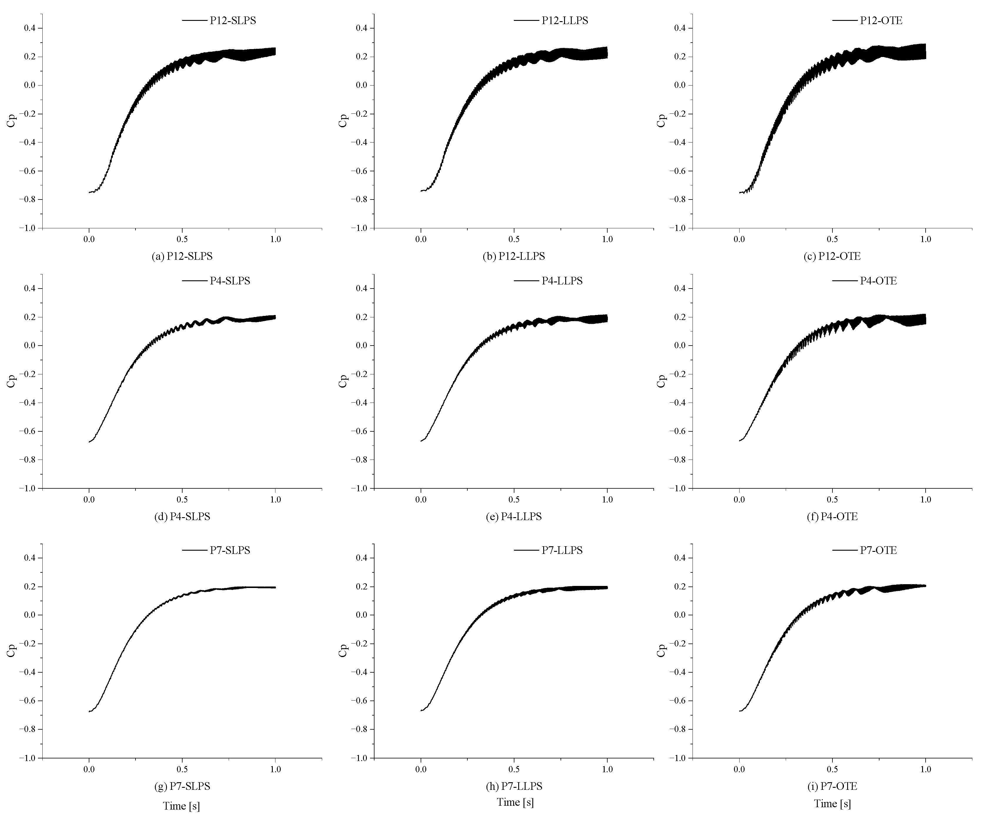
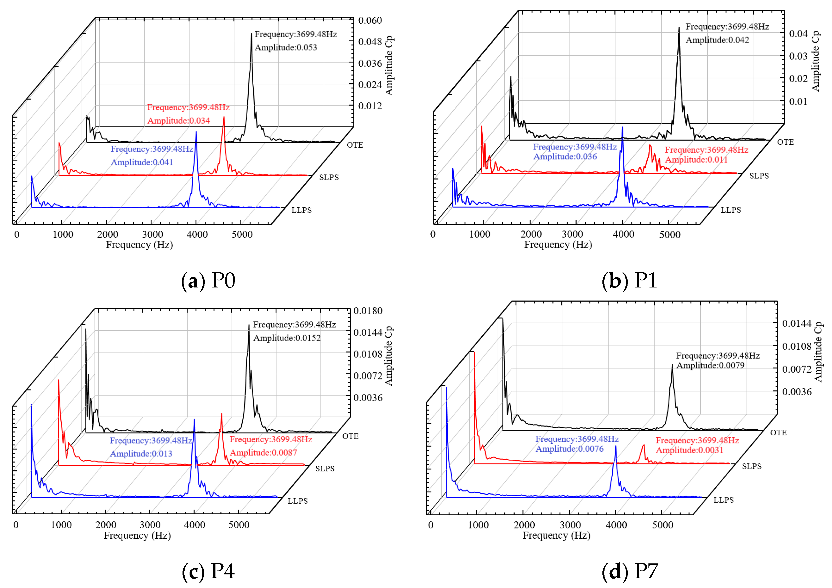
3.2. Analysis of Pressure Fluctuation

The pressure fluctuation characteristic is an important indicator of the stability of the pump, while the representative fluctuation characteristic lies in the top point of the volute casing. Specifically, P0, P1, P4, P7, P10, and P12 are the monitoring points under study. In this paper, the amplitude of pressure fluctuation is expressed as the pressure coefficient, which is defined as:
C P = Δ p 0.5 ρ u 2 2
where ρ is the density of the medium and u 2 is the circumferential velocity of impeller outlet.
Figure 9 and Figure 10 show the time-domain diagrams of pressure fluctuation coefficients at P0, P1, P10, P4, P7, and P12 monitoring points, respectively. It can be seen that the change trend of centrifugal pumps with different blade trailing edge filings is basically the same at 0−1.0 s; pressure fluctuation shows a rising trend of continuous fluctuation, there are several throat areas in the fluctuation process, and the fluctuation range of pressure fluctuation is the smallest. The distance between adjacent pressure pulsation throats also increases with time. After the last throat is generated, the pressure pulsation tends to fluctuate steadily. There are oscillations at points P0, P1, and p12 because these monitoring points are located near the volute tongue. Due to the dynamic and static interference, the eddy current generated by the rotation of the impeller causes greater pressure pulsation.
It can be seen that the blade pressure fluctuation amplitude after filing has been significantly reduced and it is easier to reach a stable state. As shown in Figure 9d–f, the LLPS pump reaches the equilibrium state at 0.8526 s, the SLPS pump reaches the equilibrium state at 0.8974 s, and the OTE pump is close to the stable state at 0.9801 s. The pressure fluctuation amplitude of the OTE pump is significantly greater than that of the centrifugal pump after two kinds of file repair, and there is also the same trend in other monitoring points, indicating that the blade pressure side file repair has a significant inhibitory effect on the vibration of the centrifugal pump during the startup process.
In order to more intuitively display the effect of suppressing pressure pulsation after blade trailing edge filing, the time-domain and frequency-domain conversion of the pulsation signal is carried out by fast Fourier transform (FFT). Since the trends before 0.5 s are basically the same, this paper conducts fast Fourier transform for the time-domain diagrams of monitoring points P0, P1, P4, and P7 after 0.5 s. Figure 11 shows the frequency domain diagrams of pressure pulsation at the outlet of the impeller at each monitoring point. The vibration signals mainly include high frequency and a small amount of low frequency signals. The main frequency of each monitoring point is 3699.48 Hz, which is 76.5 times that of the centrifugal pump under stable working conditions (48.33 Hz). The pressure coefficient amplitude of the OTE pump is the largest at point P0, which is 0.053, while the amplitude decreases at P1, P4, and P7. This is because point P0 is located near the tongue, and the dynamic and static interference is serious. Moreover, the amplitude of the SLPS pump at each monitoring point is the smallest of the three pumps, and the minimum point is at P7, which is 0.0031. It can be seen that the pressure pulsation amplitude of the filing centrifugal pump is significantly reduced, and the inhibition degree of pressure pulsation by different filing methods at different monitoring points is also different. As shown in Figure 12, in order to better analyze the maximum amplitude of the main frequency, the maximum amplitudes of the centrifugal pumps with different filing methods at all monitoring points were compared and analyzed.
As can be seen from Figure 12, the pressure pulsation amplitude of three different centrifugal pumps at all monitoring points shows the same change trend, and the maximum pressure pulsation amplitude is at P0 (volute tongue). The pressure pulsation amplitude of the monitoring points far from P0 showed a downward trend. At P6 and P7, which are farthest from P0, the amplitude of pressure pulsation reaches the minimum, which proves that the dynamic and static interference of blade and volute tongue is the main cause of high amplitude pressure pulsation, vibration, and noise. The centrifugal pump with two kinds of blades filed has the obvious ability to suppress pressure pulsation, and the LLPS centrifugal pump has the best inhibition effect. The maximum pressure pulsation amplitude of each monitoring point decreased by 32.23% on average, and the maximum pressure pulsation amplitude of the SLPS centrifugal pump decreased by 20.25% on average. The inhibition effect of centrifugal pumps is best when the water body of volute and impeller is narrow. Due to the strong interference between the liquid flowing out of the impeller and the static volute, which then causes the abnormal vibration of the centrifugal pump, the pressure pulsation and vibration energy can be effectively reduced by filing the centrifugal pump here. The maximum pressure pulsation amplitude of the LLPS pump at the P3 monitoring point is reduced by 56%.

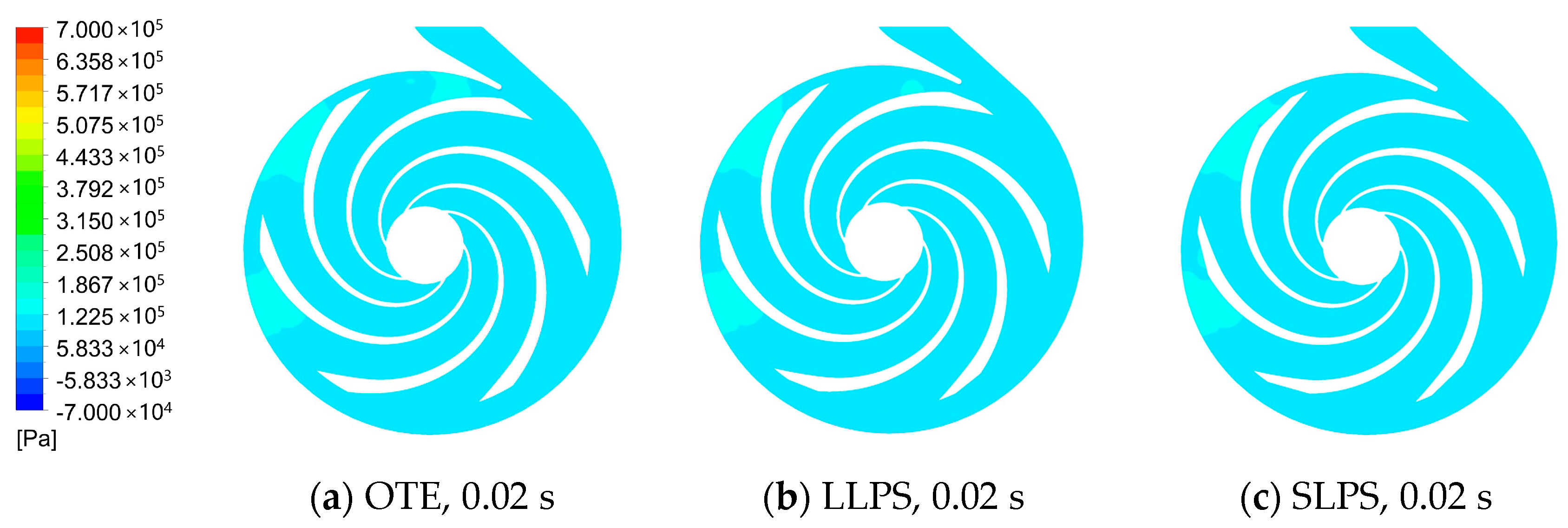
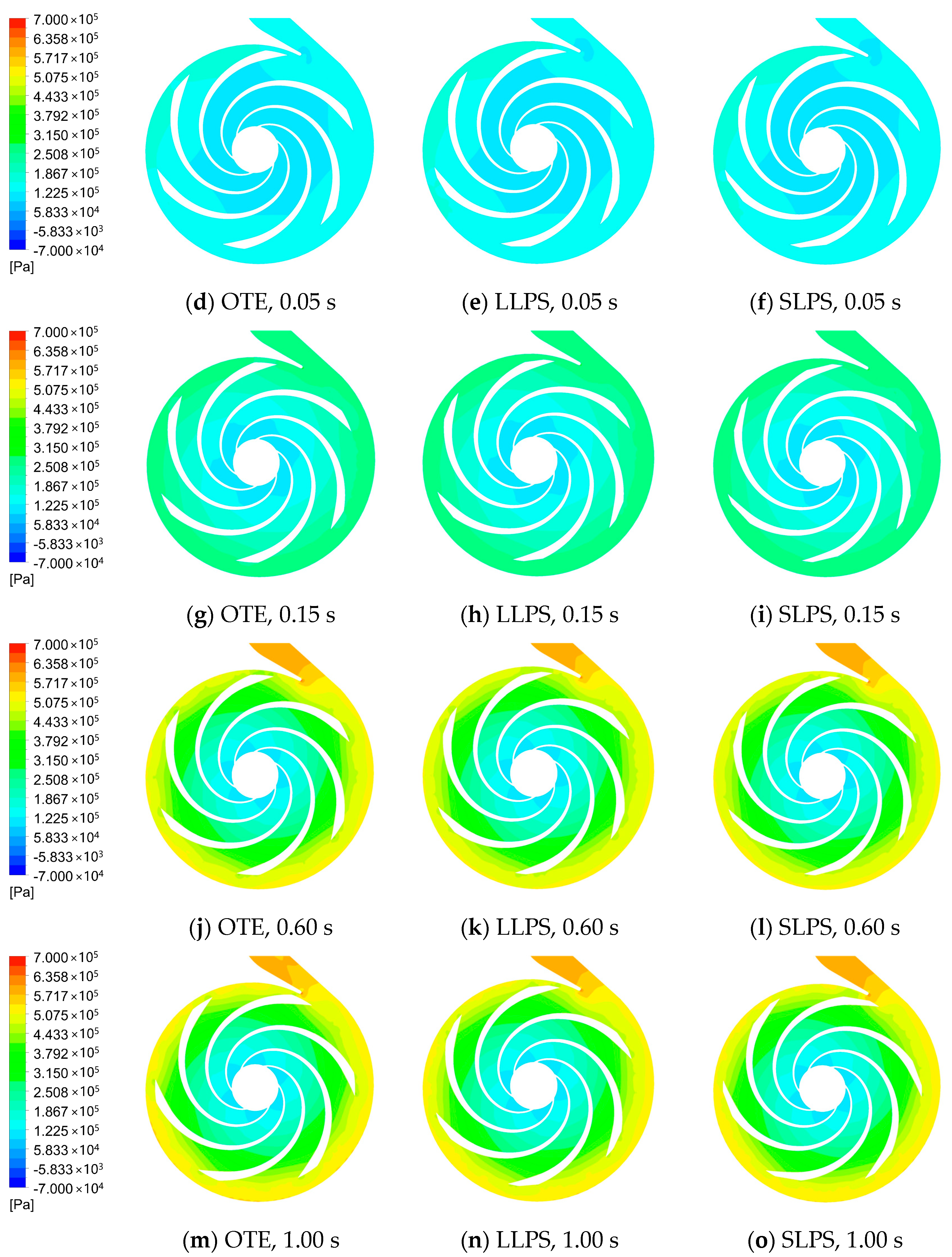
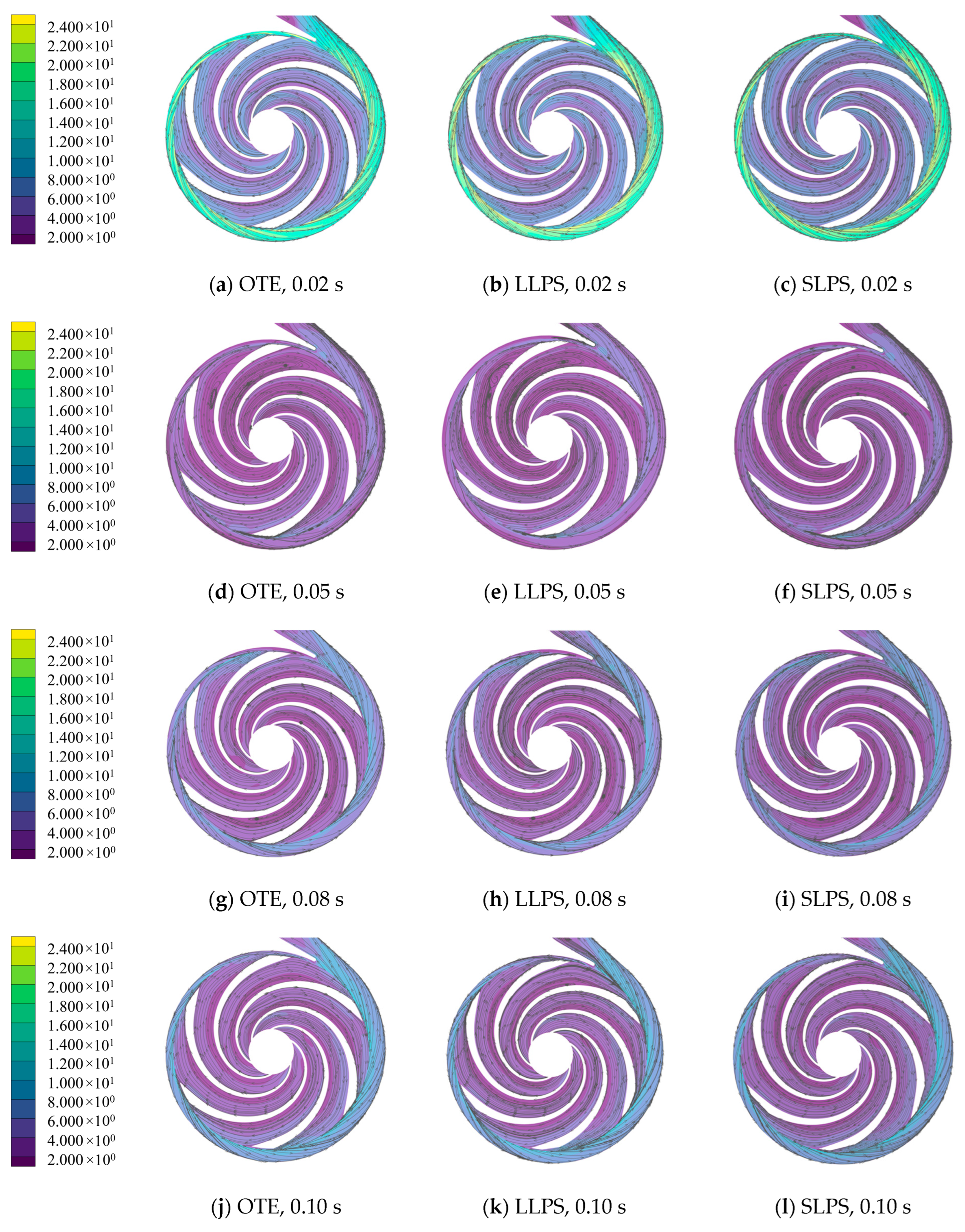
3.3. Analysis of Internal Flow Field of Centrifugal Pumps with Different Filing Blades during Startup

Figure 13 is the static pressure distribution at the middle interface of the centrifugal pump during the startup period. At 0.02 s and 0.05 s, the pressure distribution inside the impeller is uneven, and the high-pressure area is mainly concentrated in the narrow area of the volute flow channel. In the initial stage of centrifugal pump startup, the flow development in the pump is insufficient, resulting in a large-scale uneven distribution of pressure. After 0.15 s, the low-pressure area appeared at the inlet of the impeller, the high-pressure annular distribution appeared around the outer circle of the volute, and the pressure gradient near the tongue decreased. This may be because the trailing edge of the blade after filing can improve the streamline of the fluid and reduce the generation of turbulence. Thus, the energy loss and pressure loss are reduced, and the pressure inside the volute is increased. It can be seen that there is an obvious small low-pressure area at the blade outlet of the OTE pump, which is prone to flow disorder. The low-pressure areas of the LLPS and SLPS pumps at the same position are significantly reduced, and the pressure distribution at the impeller outlet is more uniform. After 0.60 s, the flow tends to be stable. It can be seen that the low-pressure area at the outlet of the blade of the OTE pump persists, and the low-pressure zones of the LLPS and SLPS pumps have disappeared. When the centrifugal pump reaches the rated speed at 1.00 s, the static pressure of the volute of the LLPS and SLPS pumps is significantly greater than that of the OTE pump, indicating that the transport capacity of the centrifugal pump has been improved after blade filing.
Figure 14 shows the distribution diagram of velocity streamline at the central section of the centrifugal pump under starting condition. As can be seen from the figure, in the initial stage of starting the centrifugal pump, the internal flow of the centrifugal pump is relatively chaotic, and a large vortex area appears on the pressure side of the three flow channels of the impeller This vortex leads to flow blockage, which influences the performance of the centrifugal pump. This may also be the reason for the phenomenon that the head and efficiency are 0 before 0.0322 s. After 0.05 s, the vortex area in all channels decreased significantly, and some split into two vortices, and the core of the vortex moves to the impeller inlet. At 0.08 s, the vortex area in the impeller channel is further reduced, and the core of the vortex is mainly concentrated in the middle of the impeller channel. At 0.10 s, only the OTE pump still has a vortex area, and the streamlines of the LLPS pump and SLPS pump, whose blades have been filed, tend to be smooth, and there is no vortex. At 0.15 s, the rated acceleration time of the centrifugal pump is reached, the speed is from static to 63.2% of the rated speed, and the flow line in the impeller channel is basically stable.
Based on the analysis of the distribution characteristics of the static pressure and velocity streamlines of the centrifugal pump at the startup period, this paper reveals the relationship between the pressure pulsation and the unsteady flow structure during the startup period from the law of vorticity, Ω , distribution, which is defined as:
Ω = 2 ω z = ( v x x v x y )
Figure 15 shows the vorticity distribution of the central section of the centrifugal pump under starting condition. As can be seen from the figure, at 0.02 s, only the high vorticity area appears near the volute tongue, which means that the flow in the pump is relatively slow at the initial stage of the centrifugal pump startup. The high vorticity area out of the tongue corresponds to the high-pressure gradient phenomenon in Figure 13. At 0.05 s, besides the tongue, there is also a large vorticity distribution area at the interface of the impeller volute, especially in the trailing edge of the blade pressure side. After 0.15 s, an obvious spatio-temporal evolution process of vortex structure can be seen: vortex is generated from the inlet of impeller and gradually spreads to the impeller suction side. With the impeller rotating periodically into the volute region, the trailing edge vortex structure of the suction side of the blade produces a shedding vortex. When the shedding vortex passes through the tongue, it is divided into two vortex structures, which develop towards the exit of the volute and the left side of the tongue. The vortex structure in the left region of the tongue is gradually reduced with the change of the volute channel. Figure 12 and Figure 13 can verify this trend. In Figure 14, the maximum amplitude of the pressure fluctuation from P0 to P11 is also a gradually decreasing trend. In Figure 15, the left static pressure of the middle section is also significantly greater than that of the right. At 1.00 s, the internal flow of the centrifugal pump tends to be stable. It is obvious that the vorticity of the SLPS impeller is significantly lower than that of the other two schemes. This may be due to the fact that the short linear filing at the trailing edge of the blade reduces the turbulence loss at the impeller outlet, improves the flow of fluid at the trailing edge of the blade, slows down the vortex separation phenomenon, and then reduces the vorticity. However, after long linear filing, the flow rate further increases, which increases the strength of vortex formation and rotation. At the same time, the increase in filing degree leads to the decrease of blade interference and the increase in vorticity.

4. Conclusions

In this paper, the startup process of the centrifugal pump tail edge filing scheme suitable for engineering practice was analyzed, the pressure fluctuation during the startup process was studied, and its internal flow mechanism was explored. The main findings are as follows:
  • During the startup period of the centrifugal pump, the external characteristic curves showed a fluctuating upward trend and have a lag phenomenon. The head of the centrifugal pump after filing has decreased, but the efficiency has improved. The blade pressure side filing can effectively reduce the amplitude of the head.
  • The blade pressure side file has a significant inhibitory effect on the pressure fluctuation during the startup process of the centrifugal pump, and the maximum pressure fluctuation amplitude at the monitoring point is reduced by 32.23% on average and the maximum pressure pulsation amplitude of the SLPS centrifugal pump decreased by 20.25% on average.
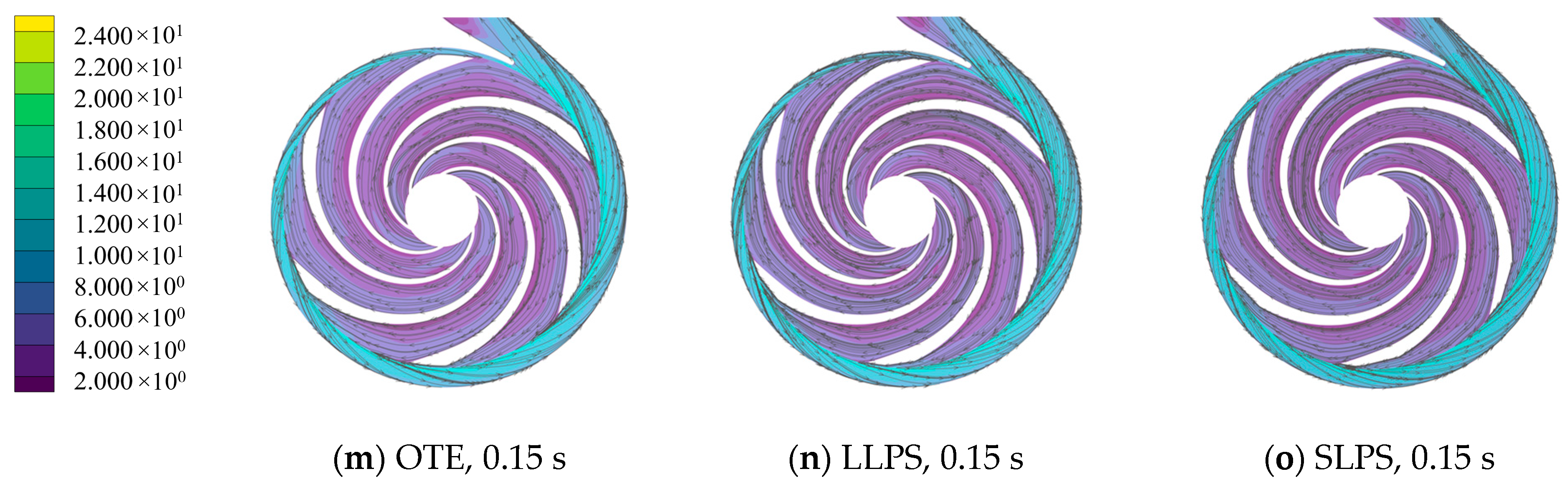
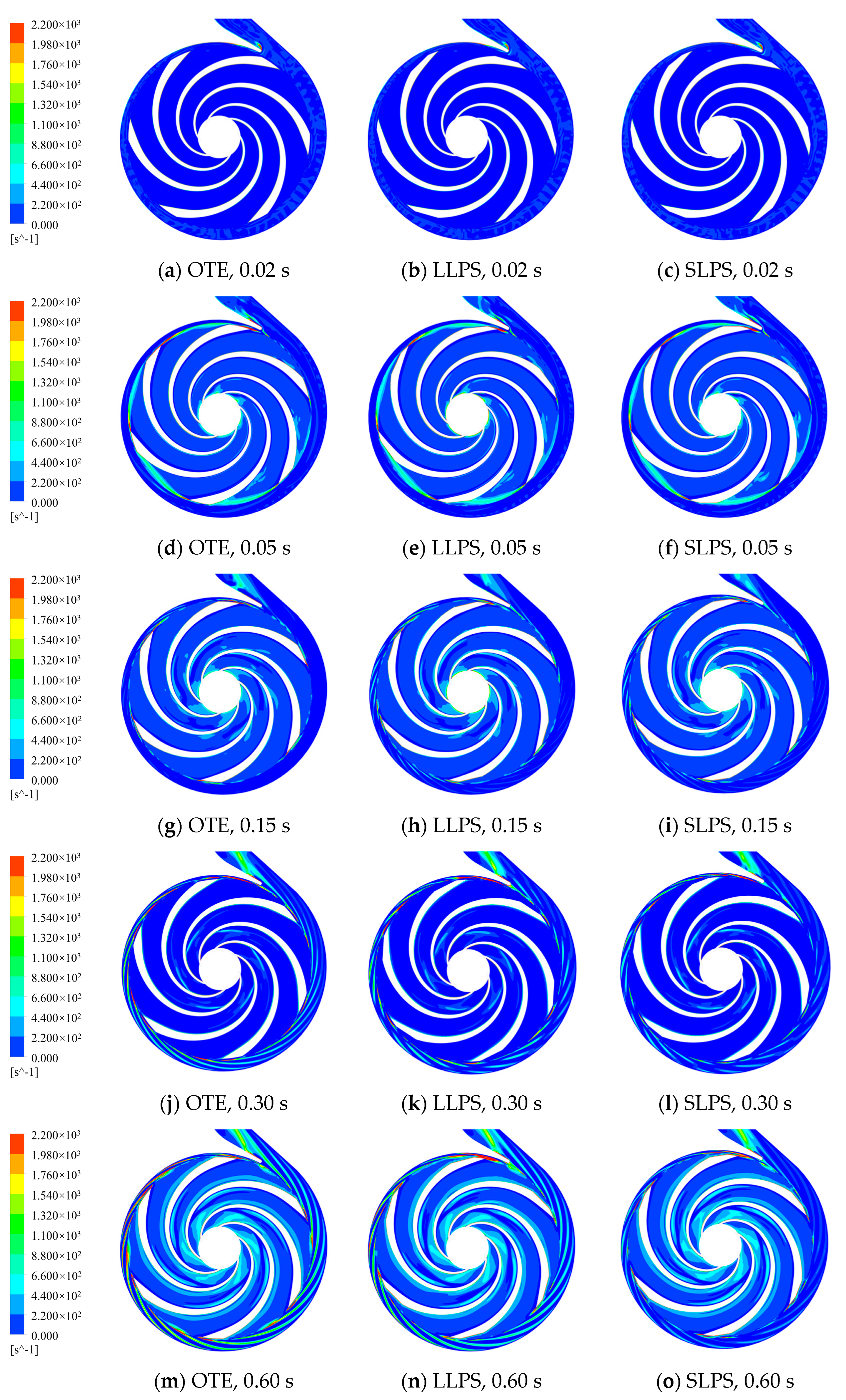
  • Through the analysis of static pressure distribution and velocity streamline, it was found that the small low-pressure area at the outlet of OTE pump blade is prone to flow disorder. The low-pressure area of the LLPS and SLPS pumps at the same location is significantly reduced, and the impeller outlet pressure distribution is more uniform. There is a large eddy current in the three flow channels in the impeller, which leads to flow blockage and makes the centrifugal pump lose pumping effect. Through vortex analysis, it was found that the vortex at the outlet of the centrifugal pump blade after trailing edge filing is significantly reduced, which effectively promotes the stability of the centrifugal pump and inhibits the pressure fluctuation.
This paper provides ideas and methods for reducing the vibration caused by pressure pulsation during the starting process of centrifugal pumps and provides theoretical support for application in practical engineering. However, this paper does not explore the energy loss and noise during the startup process, which can be further studied in the future.

Author Contributions

H.D., conceptualization, methodology, supervision; F.G., software, validation, writing—review and editing; K.W., investigation, formal analysis; F.L., data curation, software. All authors have read and agreed to the published version of the manuscript.

Funding

This research was funded by [Natural Science Foundation Project of Shandong province] grant number [ZR2019MEE068].

Data Availability Statement

No data were used for the research described in the article.

Conflicts of Interest

The authors declare that they have no known competing financial interests or personal relationships that could have appeared to influence the work reported in this paper.

References

  1. Zhang, Y.L.; Zhu, Z.C.; Li, W.G. Experiments on transient performance of a low specific speed centrifugal pump with open impeller. Proc. Inst. Mech. Eng. Part A J. Power Energy 2016, 230, 648–659. [Google Scholar] [CrossRef]
  2. Li, Z.F.; Wu, D.Z.; Wang, L.Q.; Dai, W.P.; Chen, F.Q. Experimental study on transient characteristics of centrifugal pump during start-up process. J. Drain. Irrig. Mach. Eng. 2010, 28, 389–393. [Google Scholar]
  3. Tsukamoto, H.; Asakura, J.; Tominaga, N.; Nanba, H.; Tanaka, T. Dynamic response of a cavitating centrifugal pump to fluctuating rotational speed. In Proceedings of the International Conference on Fluid Machinery, Beijing, China, 9–12 September 1996; pp. 441–448. [Google Scholar]
  4. Duplaa, S.; Coutier-Delgosha, O.; Dazin, A.; Bois, G. X-ray Measurements in a Cavitating Centrifugal Pump during Fast Start-Ups. J. Fluids Eng. 2013, 135, 41204. [Google Scholar] [CrossRef] [Green Version]
  5. Chalghoum, I.; Elaoud, S.; Akrout, M.; Taieb, E.H. Transient behavior of a centrifugal pump during starting period. Appl. Acoust. 2016, 109, 82–89. [Google Scholar] [CrossRef]
  6. Li, Z.F.; Wu, D.Z.; Dai, W.P.; Wang, L.Q. Experimental study on the transient characteristics and flows in a centrifugal pump during starting period. J. Eng. Thermophys. 2010, 31, 2019–2022. [Google Scholar]
  7. Wang, Y.; Xie, L.; Chen, J.; Liu, H.-l.; Luo, K.; Zhang, Z.-l.; Cao, M.-h. Experimental Study on Transient Startup Characteristics of a Super Low Specific Speed Centrifugal Pump. J. Chem. Eng. Jpn. 2019, 52, 743–750. [Google Scholar] [CrossRef]
  8. Li, Z.; Wu, P.; Wu, D.; Wang, L. Experimental and numerical study of transient flow in a centrifugal pump during startup. J. Mech. Sci. Technol. 2011, 25, 749–757. [Google Scholar] [CrossRef]
  9. Meng, L.; Liu, M.; Zhou, L.; Wang, W.; Liao, C.; Zhao, L.; Li, T. Coupling simulation of the fast startup of a centrifugal pump with cavitation in a closed-loop pipeline system. Eng. Comput. 2018, 35, 2010–2024. [Google Scholar] [CrossRef]
  10. Zhou, R.; Yang, J.; Liu, H.L.; Dong, L. Effect of Volute Geometry on Radial Force Characteristics of Centrifugal Pump during Startup. J. Appl. Fluid Mech. 2021, 15, 25–36. [Google Scholar] [CrossRef]
  11. Zou, Z.C.; Wang, F.J.; Yao, Z.F.; Tao, R.; Xiao, R.F.; Li, H.C. Impeller radial force evolution in a large double-suction centrifugal pump during startup at the shut-off condition. Nucl. Eng. Des. 2016, 310, 410–417. [Google Scholar] [CrossRef]
  12. Li, W.; Ji, L.L.; Shi, W.D.; Li, E.D.; Ma, L.L.; Yang, Z.Y. Particle image velocimetry experiment of the inlet flow field in a mixed-flow pump during the startup period. Proc. Inst. Mech. Eng. Part A J. Power Energy 2020, 234, 300–314. [Google Scholar] [CrossRef]
  13. Zhang, Y.L.; Li, Y.; Zhu, Z.C.; Cui, B.L. Computational Analysis of Centrifugal Pump Delivering Solid-liquid Two-phase Flow during Startup Period. Chin. J. Mech. Eng. 2014, 27, 178–185. [Google Scholar] [CrossRef]
  14. Zhang, Y.L.; Zhu, Z.C.; Dou, H.S.; Cui, B.L.; Li, Y.; Zhou, Z.Z. Numerical Investigation of Transient Flow in a Prototype Centrifugal Pump during Startup Period. Int. J. Turbo Jet-Engines 2017, 34, 167–176. [Google Scholar] [CrossRef]
  15. Dai, C.; Guo, C.; Chen, Y.P.; Dong, L.; Liu, H.L. Analysis of the Influence of Different Bionic Structures on the Noise Reduction Performance of the Centrifugal Pump. Sensors 2021, 21, 15. [Google Scholar] [CrossRef]
  16. Wang, J.; Liu, X.; Tian, C.; Xi, G. Aerodynamic performance improvement and noise control for the multi-blade centrifugal fan by using bio-inspired blades. Energy 2023, 263, 125829. [Google Scholar] [CrossRef]
  17. Kim, S.-J.; Choi, Y.-S.; Cho, Y.; Choi, J.-W.; Kim, J.-H. Effect of Runner Blade Thickness on Flow Characteristics of a Francis Turbine Model at Low Flowrates. J. Fluids Eng. 2020, 142, 31104. [Google Scholar] [CrossRef]
  18. Tao, Y.; Yuan, S.Q.; Liu, J.R.; Zhang, F.; Tao, J.P. Influence of Blade Thickness on Transient Flow Characteristics of Centrifugal Slurry Pump with Semi-open Impeller. Chin. J. Mech. Eng. 2016, 29, 1209–1217. [Google Scholar] [CrossRef]
  19. Cui, B.L.; Li, W.Q.; Zhang, C.L. Effect of Blade Trailing Edge Cutting Angle on Unstable Flow and Vibration in a Centrifugal Pump. J. Fluids Eng.-Trans. ASME 2020, 142, 15. [Google Scholar] [CrossRef]
  20. Qian, B.; Wu, P.; Huang, B.; Zhang, K.; Li, S.Y.; Wu, D.Z. Optimization of a Centrifugal Impeller on Blade Thickness Distribution to Reduce Hydro-Induced Vibration. J. Fluids Eng.-Trans. ASME 2020, 142, 12. [Google Scholar] [CrossRef]
  21. Wu, C.S.; Zhang, W.Q.; Wu, P.; Yi, J.L.; Ye, H.J.; Huang, B.; Wu, D.Z. Effects of Blade Pressure Side Modification on Unsteady Pressure Pulsation and Flow Structures in a Centrifugal Pump. J. Fluids Eng.-Trans. ASME 2021, 143, 14. [Google Scholar] [CrossRef]
  22. Chengshuo, W.; Kexin, P.; Changqin, L.; Peng, W.; Bin, H.; Dazhuan, W. Blade redesign based on secondary flow suppression to improve energy efficiency of a centrifugal pump. Energy 2022, 246, 123394. [Google Scholar] [CrossRef]
  23. Ryi, J.; Choi, J.S. Noise reduction effect of airfoil and small-scale rotor using serration trailing edge in a wind tunnel test. Sci. China-Technol. Sci. 2017, 60, 325–332. [Google Scholar] [CrossRef]
  24. Gao, B.; Zhang, N.; Li, Z.; Ni, D.; Yang, M.G. Influence of the Blade Trailing Edge Profile on the Performance and Unsteady Pressure Pulsations in a Low Specific Speed Centrifugal Pump. J. Fluids Eng.-Trans. ASME 2016, 138, 10. [Google Scholar] [CrossRef]
  25. Huang, B.; Zeng, G.T.; Qian, B.; Wu, P.; Shi, P.L.; Qian, D.Q. Pressure Fluctuation Reduction of a Centrifugal Pump by Blade Trailing Edge Modification. Processes 2021, 9, 19. [Google Scholar] [CrossRef]
  26. Fecarotta, O.; Messa, G.V.; Pugliese, F. Numerical assessment of the vulnerability to impact erosion of a pump as turbine in a water supply system. J. Hydroinforma. 2020, 22, 691–712. [Google Scholar] [CrossRef]
Figure 1. 3D model of centrifugal pump.
Processes 11 02420 g001
Figure 2. Schematic diagram of blade outlet filing.
Processes 11 02420 g002
Figure 3. Grid diagram of centrifugal pump.
Processes 11 02420 g003
Figure 4. Locations of monitoring point.
Processes 11 02420 g004
Figure 5. Experimental test platform.
Processes 11 02420 g005
Figure 6. External characteristic curve of low specific speed centrifugal pump.
Processes 11 02420 g006
Figure 7. External characteristic curves of centrifugal pumps with different blade trailing edges during startup.
Processes 11 02420 g007
Figure 8. Head fluctuation frequency characteristics with different blade trailing edges.
Processes 11 02420 g008
Figure 9. Time domain pressure pulsation at monitoring points in centrifugal pumps with different blade edges (P0, P1, P10).
Processes 11 02420 g009
Figure 10. Time domain pressure pulsation at monitoring points in centrifugal pumps with different blade edges (P4, P7, P12).
Processes 11 02420 g010
Figure 11. Flow channel outlet pressure pulsation frequency domain diagram.
Processes 11 02420 g011
Figure 12. Distributions of pressure amplitude at volute channel.
Processes 11 02420 g012
Figure 13. Static pressure distribution of middle section of centrifugal pump under startup condition.
Processes 11 02420 g013aProcesses 11 02420 g013b
Figure 14. Velocity streamline distribution in the middle section of the centrifugal pump under starting state.
Processes 11 02420 g014aProcesses 11 02420 g014b
Figure 15. Vorticity distribution of the middle section of the centrifugal pump at the startup period.
Processes 11 02420 g015aProcesses 11 02420 g015b
Table 1. Main structural parameters of the model pump.
ParametersValue
Design flow rate/Qd12.5 m3h−1
Head/Hd50 m
Rotating speed/n2900 rpm
Impeller blade number/Z6
Impeller inlet diameter/D150 mm
Impeller outer diameter/D2198 mm
Blade outlet width/b24 mm
Volute inlet diameter/D3205 mm
Volute outer diameter/D432 mm
Volute inlet width/b312 mm
Table 2. Computational domain grid scheme.
Test CaseImpeller Mesh ElementsVolute Mesh ElementsStator Mesh ElementsOutlet Mesh ElementsTotal Mesh ElementsRelative HeadRelative Efficiency
1973,794638,384312,900301,8002,216,9181.004538441.00120579
21,448,054824,976478,500362,1602,995,7701.001475281.00094366
31,731,326999,268572,100434,5923,603,9641.000000001.00000000
41,933,4061,477,016672,900521,5164,389,6100.999594290.99819130
Disclaimer/Publisher’s Note: The statements, opinions and data contained in all publications are solely those of the individual author(s) and contributor(s) and not of MDPI and/or the editor(s). MDPI and/or the editor(s) disclaim responsibility for any injury to people or property resulting from any ideas, methods, instructions or products referred to in the content.

