Review

A Comprehensive Review Regarding Condensation of Low-GWP Refrigerants for Some Major Alternatives of R-134a

1
Department of Mechanical Engineering, National Yang-Ming Chiao Tung University, Hsinchu 300, Taiwan
2
Green Energy & Environment Research Laboratories, Industrial Technology Research Institute, Hsinchu 310, Taiwan
*
Author to whom correspondence should be addressed.
Processes 2022, 10(9), 1882; https://doi.org/10.3390/pr10091882
Submission received: 22 August 2022 / Revised: 9 September 2022 / Accepted: 13 September 2022 / Published: 17 September 2022

Abstract

:
In this review, the condensation HTCs (heat transfer coefficients) and pressure drop characteristics of some major low-global-warming-potential (GWP) refrigerants alternative to R-134a such as R-1234ze(E), R-1234ze(Z), R-1234yf, R-513A, and R-450A are reviewed. The thermofluids’ characteristics inside/outside a tube, minichannel, microfin tube, and plate heat exchanger are examined. In addition, several other refrigerants attributed to low GWP are also included in the present review. The experimental/numerical/simulation results’ analysis reveals that condensation HTCs and pressure drop characteristics depend on several parameters such as thermodynamics and transport properties of the working fluid, mass flux of the refrigerants, heat flux, saturation temperature, vapor quality, flow patterns, flow conditions, orientation of the condensing geometry, and condensation geometry (shape, size, and smooth/enhanced).

1. Introduction

During the past few decades, among the numerous hydrofluorocarbon (HFC) refrigerants, R-134a (CH2FCF3) has been the most widely used working fluid in air conditioning and refrigeration systems due to its superior heat transfer performance characteristics either in condensation or boiling. However, the high GWP (R-134a: 1300) associated with it is a major contributing factor to global warming and the use of this common refrigerant should be reduced by 85% before 2047 according to the Kigali amendment to the Montreal Protocol (IPCC AR6) and F-gas regulation. Therefore, efforts to find an alternative to R-134a have intensified in recent years. However, replacing the refrigerant used in a refrigerated air-conditioning system is not a quick and easy process as it must meet a series of criteria, such as GWP, ODP, flammability, toxicity, compatibility with lubricating oil, cost, thermophysical properties, and refrigeration effect, as depicted in Figure 1. Although facing all the challenges, the American Society of Heating, Refrigerating and Air-Conditioning Engineers (ASHRAE) and Alternative Refrigerants Evaluation Program (AREP) technical committee has listed potential substitutes for R-134a, such as R-1234yf, R-1234ze(E), R-1234ze(Z), R-513A, R-450A, and R-1233zd(E), known as a hydrofluoroolefins (HFOs) refrigerant. The subscript: ze, yf, and zd contain a carbon–carbon double bond which is a key feature that facilitates the low-GWP characteristic and these molecules have also a low atmospheric lifetime compared to the HFC refrigerants. Moreover, the suffix (E: trans) and (Z: cis) indicate that it is an isomer with different physical properties. The thermodynamic and transport properties of alternative refrigerants and baseline refrigerants at 40 °C are listed in Table 1.
R-1234yf and 1234ze(E) are single-component refrigerants having a GWP of less than 1, are mildly flammable, and have comparable energy efficiency to R-134a. R-513A is an azeotropic blend of R-1234yf (56%) and R-134a (44%), a nonflammable, nontoxic refrigerant with 55.93% lower GWP as compared to R-134a. The main advantage of R-513A is that it is compatible with existing R-134a systems. Similarly, R-450A is a zeotropic blend of R-134a (42%) and R-1234ze(E) (58%), having a temperature glide of 0.4 °C, is nonflammable and slightly toxic, and is a 57.92% lower-GWP refrigerant compared to R-134a. In addition, R-1233zd(E) (GWP: <1, ODP: 0.00034, ASHRAE class: B1) is an alternative refrigerant to R-123/R-245fa which is most often used to cool large buildings and low-pressure centrifugal chillers.
Condensation is the major heat transfer process in the typical condensers of HVAC systems; effective condensation can well control the system pressure and manage the heat transfer to system efficiency. Conversely, inadequate condensation can reduce the system performance and yield high pressure that may damage the whole system. Therefore, condensing heat transfer characteristics of the working fluid is equally important as boiling/evaporation heat transfer characteristics in the HVAC systems. With the advent of new fourth-generation HFO low-GWP refrigerant, there are numerous studies regarding the condensing heat transfer performance of low-GWP refrigerants which have been reported in the past decades. A thorough analysis of condensation investigations inside microchannels from the previous two decades was presented by Kadi et al. [2]. Fronk and Garimella [3] reviewed the in-tube condensation of zeotropic fluid mixtures. Ho and Leong [4] critically reviewed film-wise natural/forced convection condensation on enhanced surfaces which mostly focused on HFC refrigerants. Mauro et al. [5] reviewed the flow pattern, condensation, and boiling inside and outside smooth and enhanced surfaces of propane (R-290) only. Shon et al. [6] reviewed the condensation and evaporation characteristics of low-GWP refrigerants in plate heat exchangers. Tao and Ferreira [7] reviewed the heat transfer and frictional pressure drop during condensation in plate heat exchangers.
The aforementioned literature reveals that previously reviewed articles are limited in some manners such as working fluid (refrigerants) [5], condensation inside the tube [3] and microchannels [2], condensation inside/outside on the enhanced surface [4], and a plate heat exchanger [6,7]. Therefore, the major goal of this review is to examine the condensation heat transfer and the frictional pressure drop characteristics for low-GWP refrigerants focused on R-134a alternatives subjected to the outside/inside of a smoot/enhanced tube, inside minichannels, and brazed plate heat exchangers. In addition, the influence of thermophysical/transport properties of the working fluid, saturation temperature, condensing geometry, mass flux, heat flux, and vapor quality on condensation HTCs and pressure drop characteristics are discussed in detail.

2. Condensation Heat Transfer Characteristics of Low-GWP Refrigerants

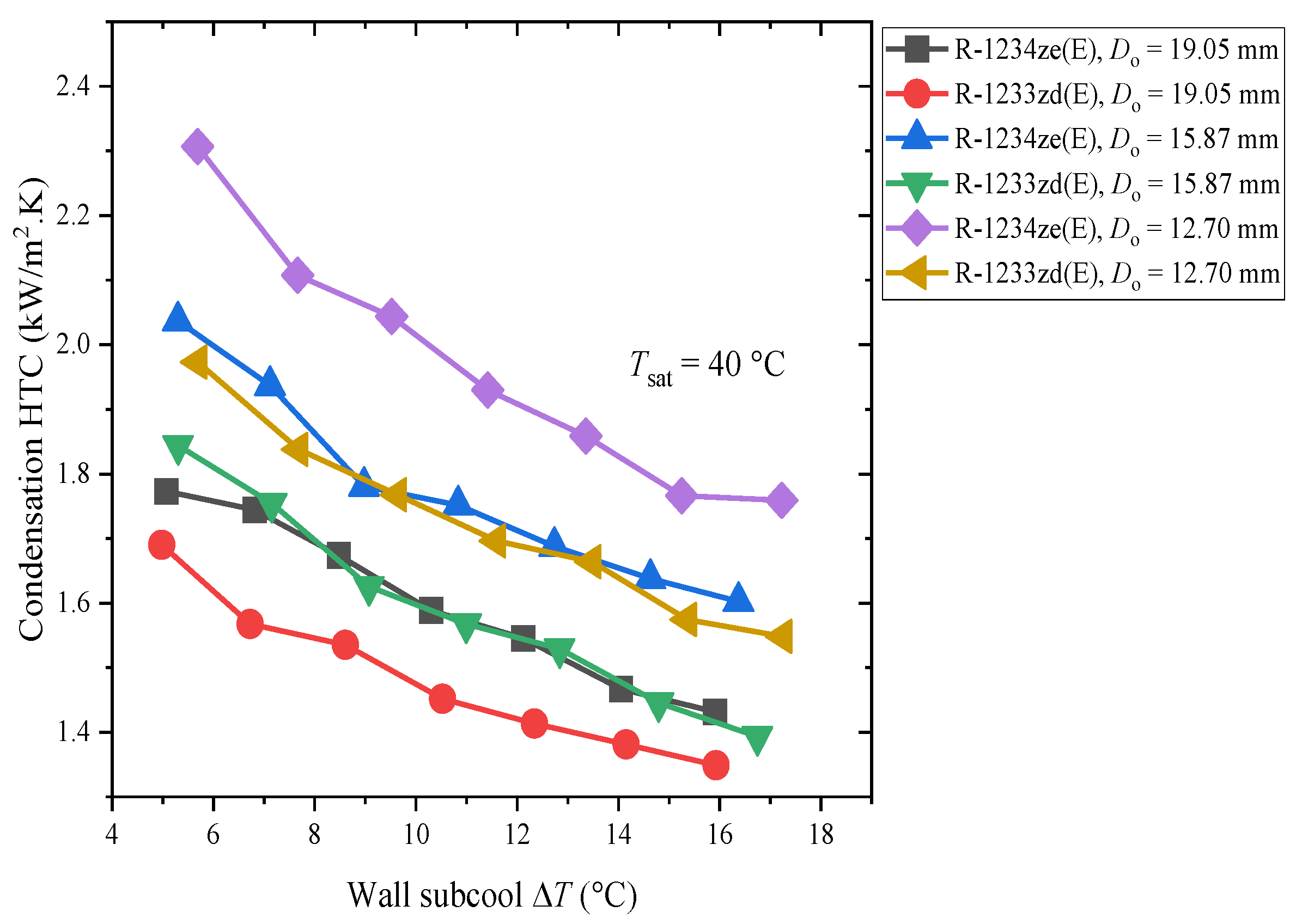
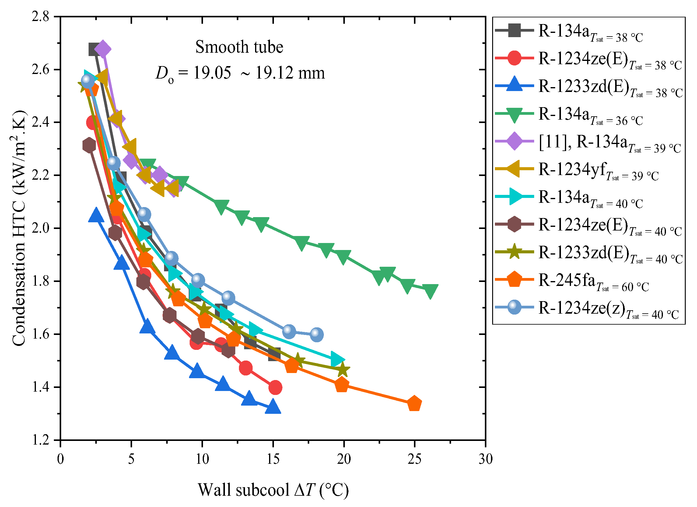
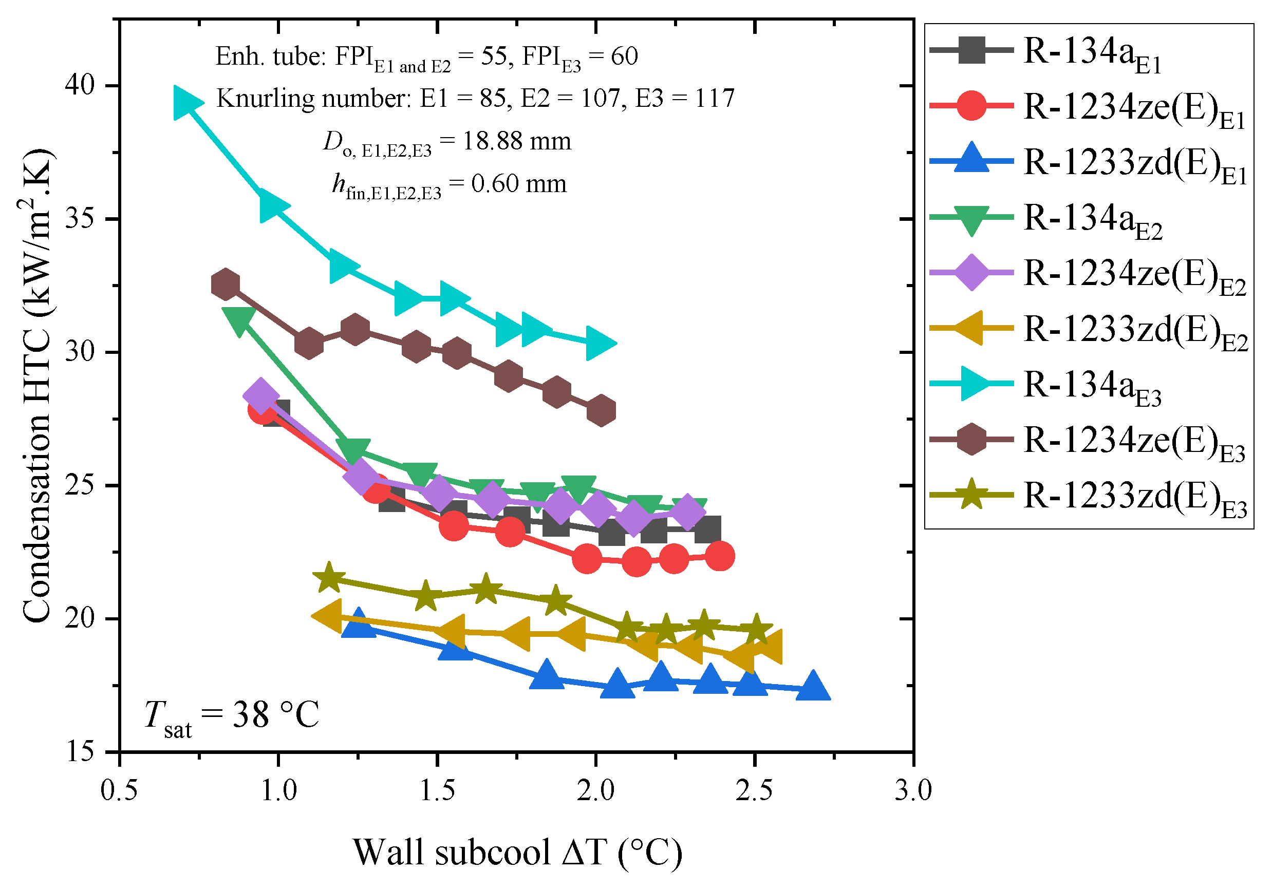
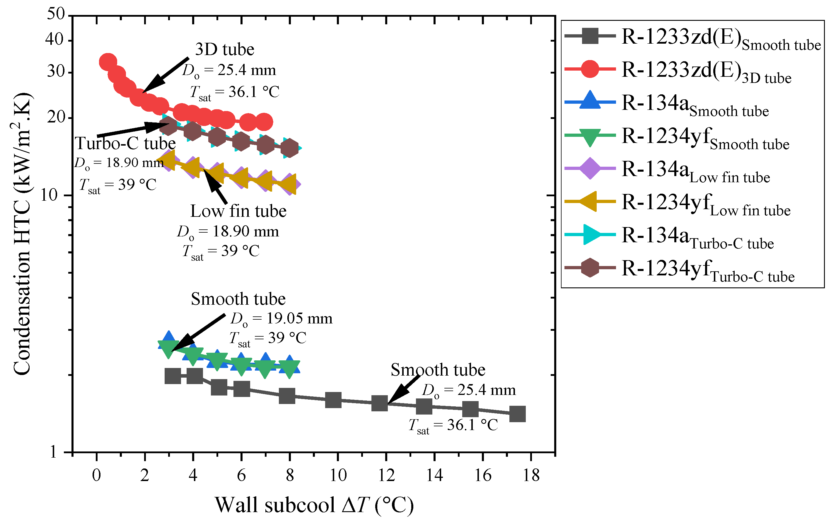
2.1. Condensation Outside the Smooth and Enhanced Tube

In this section, the condensation heat transfer characteristics of R-134a, and its alternative low-GWP refrigerants outside smooth/enhanced tubes, are reviewed. In order to compare the condensation HTCs of low-GWP refrigerants relative to R-134a, nearly 500 data points were collected from different past-decade sources from the literature subjected to experimental conditions and condensing-geometry specifications. The experimental conditions, tube dimensions, and specifications are listed in Table 2.
The experimental investigations by Ko et al. [8] on the film condensation HTCs of R-1234ze(E) and R-1233zd(E) over horizontal plain tubes (diameter: 12.70 mm, 15.87 mm, and 19.05 mm) at saturation temperatures of 40 °C are presented in Figure 2. Figure 2 reveals that with increasing surface-subcooling temperature, condensation HTCs decreased and the smallest tube diameter exhibited the highest condensation HTCs. Comparatively, when the tube diameter was decreased from 19.05 mm to 15.87 mm and 12.70 mm, the average condensation HTCs for R-1234ze(E) increased by 7.1% and 16.1%, respectively, and for R-1233zd(E), the average condensation HTCs increased by approximately 10.4% and 22.6%, respectively. Moreover, Ko et al. [8] also performed the experiment at saturation temperatures of 36 °C and 38 °C and observed that the influence of saturation temperatures on the condensation HTCs was negligible. Overall, the condensation HTCs for R-1234ze(E) were 8.22% to 23.26% higher than that of R-1233zd(E) under the same experimental conditions.
The comparative condensing heat transfer performance of low-GWP refrigerants R-1234yf, R-1234ze(E), R-1234ze(Z), and R-1233zd(E) as alternatives to R-134a is depicted in Figure 3. Ko and Jeon’s [9] studies exhibited that the average film condensation HTC of R-1233zd(E) and R-1234ze(E) was 10.04% and 10.97% lower as compared to R-134a, respectively. For R-134a and R-1234ze(E), a similar condensation HTC was also shown by Nagata et al. [12]. However, for the R-1233zd(E) and R-1234ze(Z), the condensation HTCs of Nagata et al.’s [12] results are quite contradictory when compared to Ko and Jeon [9], and even their own results, because R-1233zd(E) and R-1234ze(Z) showed higher condensation HTCs than R-1234ze(E) and R-134a, respectively. According to Park et al. [11], whose experimental test results are shown in Figure 3, the condensation HTCs of R-1234yf were remarkably similar to those of R-134a. Moreover, Ko and Jeon [9] investigated the film condensation HTCs of R-134a, R-1234ze(E), and R-1233zd(E) on three types of enhanced tubes, namely E1, E2, and E3. E1 and E2 have the same fins per inch (FPI) of 55 with knurling numbers 85 and 107, respectively, while E3 has 60 FPI with knurling number 117. Figure 4 indicates that the tube with the highest FPI and knurling number (E3) showed the highest condensation HTC for all refrigerants, and the condensation HTC decreased with increasing wall subcool temperature/heat flux. The authors of [9] observed that the FPI number had a greater influence on the condensation HTC than the knurling number. However, R-134a displayed the highest film condensation HTCs for all the enhanced tubes, while R-1233zd(E) displayed the lowest HTC. In particular, for E1, the average condensing HTCs of R-1234ze(E) and R-1233zd(E) were 1.87% and 27.44% lower than that of R-134a. For E2, the average condensation HTCs of R-1234ze(E) and R-1233zd(E) were 4.67% and 27.76% lower than that of R-134a. For E3, the average condensation HTCs of R-1234ze(E) and R-1233zd(E) were 11.83% and 41.18% lower than that of R-134a. Therefore, these findings suggest that when the condensing surface area increases, the decrease in film condensation HTC increases for each refrigerant.
Ji et al. [10] investigated the influence of fin thicknesses on the film-wise condensation HTC of R-134a, R-1234ze(E), and R-1233zd(E) outside the finned tubes. The tubes T-C1 and T-C2 have the same fin density and similar fin height while the fin thickness is different. Figure 5 shows that a tube having a thicker fin thickness has comparatively higher HTCs than a thinner-fin-thickness tube. For R-134a, the condensing HTC of T-C2 was 0.8 to 4.1%, 11.9 to 13.8%, and 10.3 to 19.7% higher than T-C1 for R-134a, R-1234ze(E), and R-1233zd(E), respectively. Moreover, in terms of low-GWP-refrigerant performances, the condensing HTC of R-134a was nearly 2 times higher than R-1233zd(E) and 10 to 20% higher than R-1234ze(E), respectively. However, in terms of condensing HTC trends, Ko and Jeon’s [9] results showed that the condensing HTCs of R-134a, R-1234ze(E), and R-1233zd(E) decreased with an increasing wall subcool temperature. On the other hand, Ji et al. [10] results exhibited that the influence of increasing wall subcool temperature on condensing HTCs was almost negligible for R-134a and R-1234ze(E), while the condensing HTCs of R-1233zd(E) increased with the increasing wall subcool temperature.
Ji et al. [13] investigated the condensation of R-134a, R-1234ze(E), and R-290 (GWP: 3, but highly flammable) outside the smooth and enhanced titanium tubes. From Figure 6, it is evident that the condensation HTC decreased with increasing wall subcool temperature. It should be noted that Ji et al.’s study in [13] differs from Ji et al.’s study in [10] and Ko and Jeon’s study [9] because the condensing HTC of R-1234ze(E) on the smooth tube was nearly similar to R-134a, while the condensing HTC of R-290 was lower than that of R-134a and R-1234ze(E) on the smooth tube and similar to R-1234ze(E) on the titanium-enhanced tube. Moreover, on the titanium-enhanced-tube, the condensation HTC of R-134a was the highest compared to R-1234ze(E) and R-290.
Moreover, Figure 7 compares the condensation HTCs of R-134a, R-1234yf, and R-1233zd(E) on an enhanced and smooth surface. Chen and Wu’s [14] investigation on the condensation HTCs of R-1233zd(E) for a smooth tube and 3D enhanced tube (2D helical ribs inside and 3D fins outside) showed that the condensation HTC of the 3D enhanced surface was nearly 10.8 times higher than the smooth tube and the condensation HTC degraded with the increasing wall subcool temperature difference. Yet, the trend of degradation in the condensation HTC was nearly the same for both tubes. In addition, Park et al.’s [11] study on the condensing HTC of R-1234yf and R-134a on plain, low-fin, and Turbo-C tubes reveals that the condensation HTCs of R-134a and R-1234yf were almost identical for all three tubes. However, among all the tubes as depicted in Figure 7, it should be noted that the 3D enhanced tube exhibited the highest condensation HTC (even with the low-pressure refrigerant R-1233zd(E)) followed by the Turbo-C, low-fin, and smooth tube.
Reif et al. [16] investigated the condensation HTC of iso-propanol, n-pentane, n-heptane, iso-octane, and water on low-finned carbon steel, stainless steel, and titanium tubes and demonstrated that the condensation HTCs of the above-mentioned enhanced tubes were 3 to 8 times higher than those of a smooth tube. Sajjan et al. [17] performed a nondimensional regression analysis for the condensation of R-600a over finned tubes. Their finding suggested that with increasing wall subcooling temperature, the enhancement factor (EF) first increases and then decreases, which gives the concept of optimum wall sub-cooling temperature.

2.2. Condensation HTC and Pressure Drop Characteristics Inside the Smooth Tube, Microfin Tube, and Minichannel

In this section, the condensation HTC and pressure drop characteristics of low-GWP refrigerants inside the smooth tube, microfin tube, and minichannels are reviewed. The details of experimental conditions and dimensional specifications of smooth tubes, microfin tubes, and minichannels available in the literature are listed in Table 3.

2.2.1. Condensation Inside the Smooth Tube

Guo et al. [18] studied the condensation HTC of low-GWP refrigerants R-161 (GWP: 12), R-290 (GWP: 3), R-32, R-41 (GWP: 92), and R-1234ze(E) inside a smooth horizontal tube ( D i = 2 mm) considering R-32 and R-134a as baseline refrigerants at saturation temperatures of 35 °C to 45 °C. Their results show (Figure 8) that with the increasing saturation temperature and heat flux, the condensation HTC decreased. The condensation HTCs of R-161, R-290, R-32, and R-41 were higher than R-134a. The HTCs of R-161 were the largest, while the HTCs of R-1234ze(E) were the lowest and 10% lower than those of R-134a. The pressure drop was directly proportional to the mass flux of the refrigerant and inversely proportional to saturation temperature. At the same condition, the pressure drops of R-161 and R-290 were the largest, followed by R-134a and R-1234ze(E), while the pressure drops of R-41 and R-32 were the lowest.
Jacob et al. [19] experimentally investigated the condensation HTCs of R-134 and R-450A inside a horizontal smooth tube ( D i = 4.7 mm) at saturation temperatures of 45 °C and 55 °C. Their results exhibited that the average condensation HTCs of R-450A were 5% lower as compared to R-134a and the average pressure drop was 8% higher than that of R-134a.
Yang and Nalbandian [20] reported the condensation HTCs and pressure drop characteristics of R-1234yf and R-134a inside a horizontal smooth tube ( D i = 4.00 mm). Their results showed that in the entire vapor quality range, the average condensation HTCs of R-134a were roughly 10% higher than those of R-1234yf and the pressure drops of R-134a were very close to those of R-1234yf when the vapor quality was less than 0.3, but when vapor quality exceeded 0.4, then the pressure drop was up to 22% higher than R-1234yf for the same mass flux (G = 200 kg/m2s). Moreover, the authors of [20] noticed that the pressure drops of R-1234yf were always lower than R-134a at higher mass flux (1200 kg/m2s), even in the lower-vapor-quality region, because R-134a has a 16% lower vapor density than R-1234yf. This suggests that for the same mass flux and vapor quality, R-134a has a higher vapor velocity than R-1234yf. However, R-134a had a liquid and vapor viscosity that is approximately 27% and 5.6% higher than R-1234yf, respectively. The pressure drop of R-134a was up to 22% higher than those of R-1234yf as a result of these two effects.
Hossain et al. [21] experimentally investigated the condensation HTCs and pressure drop of R-1234ze(E), R-32, and R-410A inside a horizontal smooth copper tube ( D i = 4.35 mm) at saturation temperatures of 35 °C and 45 °C. Their experimental results indicate that the condensation HTCs of R-1234ze(E) were nearly 20 to 45% lower than R-32 but 10 to 30% higher than R-410A. The authors of [21] noticed that influence of saturation temperature on condensation HTC was negligible at a low mass flux (200 kg/m2s) while it increased with increasing mass flux (300 kg/m2s) and, overall, HTCs decreased with an increase in saturation temperature. In particular, the condensation HTCs of R-1234ze(E) are strongly dependent on the mass flux. For example, at G = 200 kg/m2s, the HTCs of R-1234ze(E) were ≈ the HTCs of R-410A and at G = 400 kg/m2s, the HTCs of R-1234ze(E) ≈ the HTCs of R-32 due to the fact that R-1234ze(E)’s HTCs exhibit greater forced convection condensation dominance than R-32 and R-410. The average pressure drop of R-1234ze(E) was nearly 48% and 64% higher than R-32 and R-410A, respectively, at G = 350 kg/m2s, because R-1234ze(E) is a low-pressure and high-viscosity refrigerant compared to R-32 and R-410A. The pressure drop increased with increasing mass flux and vapor quality. Since the vapor density of R-1234ze(E) is lower than R-32 and R-410A, the vapor velocity is high and it causes a larger increase in pressure drop with increasing mass flux.
Wang et al. [22,23] investigated the condensation HTCs and pressure drop characteristics of R-1234yf, R-134a, and R-32 inside horizontal smooth tubes ( D i = 2 and 4 mm) at saturation temperatures of 40, 45, and 50 °C. At low mass fluxes (100 ≥ G ≥ 200 kg/m2s), the differences in the condensation HTC were minimal because the flow patterns are largely dominated by gravity. However, at higher mass flux G ≥ 200 kg/m2s, the condensation HTC increased with an increase in mass flux and vapor quality, and the HTCs within the 2 mm tube were close to or even higher than that of the 4 mm tube. In annular flow regimes, the HTC is primarily influenced by mass flux and vapor quality. The condensation HTC slightly decreases as the saturation temperature increases, because of the liquid/gas density ratio and the fact that the thermal conductivity of the liquid decreases with an increase in saturation temperature. In the case of mass flux of 400 kg/m2s, there were large differences relatively. The influence of tube diameter on the HTC was more significant at low mass flux. At a mass flux of 100 kg/m2s, the HTC of R-1234yf within the 2 mm tube was on average 35% lower than that within the 4 mm tube, while at the mass flux from 200 to 400 kg/m2s, the HTC within the 2 mm tube was almost the same as that of 4 mm. Longo et al. [24] reported the comparative performances of R-404A and its low-GWP substitutes R-290 and R-1270 inside a horizontal smooth tube ( D i = 4 mm) at saturation temperatures of 30, 35, and 40 °C. Their results showed that R-1270 and R-290 had 10 to 20% higher condensation HTCs than R-404A, and R-1270 exhibited a 15 to 30% lower pressure drop than R-290 and 20 to 60% lower than that of R-404A under the same operating conditions. Condensation HTCs of low-GWP refrigerants inside the smooth tube from different studies at mass flux 400 kg/m2.s are presented in Figure 9.
Lips and Meyer [25,26] conducted an experimental study on the condensation HTC of R-134a inside an inner diameter D i = 8.38 mm smooth tube in inclined orientations from vertical downwards to vertical upwards flow at a saturation temperature of 40 °C. They observed that the flow pattern was strongly dependent on the inclination angle for low mass fluxes and vapor qualities; however, regardless of the tube orientation, it maintained an annular shape for high mass fluxes and high vapor quality. Their research revealed that for downward flow, there is an optimum inclination angle that produces the maximum HTC. The liquid and vapor distributions, in particular the liquid thickness at the tube’s bottom for stratified flows, have a significant impact on the HTC. It was noticed that the condensation HTCs increased up to 20% when the inclination angle was 15° for downward flow but the HTCs can also be decreased for upward flows. For high mass fluxes and high vapor qualities, the flow remains annular and the condensation HTC is constant whatever the inclination because the shear forces are predominant. However, for upward flows, pressure drops are independent of the inclination angle, whereas for downward flows, pressure drops seem to depend on the inclination angle.
Agarwal and Hrnjak [27] investigated the condensation HTCs and pressure drop characteristics of R-134a, R-1234ze(E), and R-32 at saturation temperatures of 30 to 50 °C inside a horizontal smooth tube ( D i = 6.1 mm). Their results showed that R-134a exhibited 10% higher and 20% lower condensation HTCs compared to R-1234ze(E) and R-32, respectively. The HTC was highly influenced by mass flux, declined as saturation temperature rose, and was unaffected by heat flux. However, compared to R-134a and R-32, R-1234ze(E) showed a considerably larger pressure drop. R-32 had the highest HTCs and lowest pressure drop compared to R-1234ze(E) and R-134a.
Macdonald and Garimella [28,29] measured the condensation HTC and pressure drop characteristics of R-290 inside horizontal smooth tubes ( D i = 7.75 and 14.45 mm) at a saturation temperature of 30 °C to 94 °C. Their results exhibited that the pressure drop and condensation HTC decreased with the increase in saturation temperature while it increased with an increase in mass flux and vapor quality. The smaller-diameter tube exhibited a larger pressure drop because it had greater velocity gradients at the tube wall. The authors of [28,29] noticed that tube diameter is less important in determining the HTC than it is for pressure drop. However, the increasing trend in HTCs with tube diameter is more significant at higher reduced pressures. Jajja et al. [30] reported the condensation HTCs of R-454B, R-32, and R-410A inside a ( D i = 7.90 mm) smooth copper tube at saturation temperatures of 35 and 50 °C. Their tested results indicated that the HTCs increased with the increasing vapor quality and mass flux. The average HTCs decreased when saturation temperature increased. The condensation HTCs of R-32 were higher than those of R-454B.
Lee et al. [31] investigated the condensation HTCs and pressure drop characteristics of R-448A, R-449A, R-455A, R-454C, and R-404A inside a 5.6mm-diameter tube. Lee et al.’s [31] study revealed that the condensation HTCs of the alternative refrigerants were nearly the same as those of R-404A at low mass flux up to 200 kg/m2s and at a high mass flux ( G = 400 kg/m2s); the HTCs of the alternative refrigerants were higher than those of R-404A. Additionally, the associated pressure drops of the alternative refrigerants were larger than those of R-404A. Moreover, long-term refrigerants (R-454C and R-455A) yielded larger pressure drops than short-term refrigerants (R-448A and R-449A), probably due to the difference in vapor density. However, it is worthy to note that the temperature glides of alternative refrigerants were significantly larger than that of R-404A, which has an adverse effect on HTC.

2.2.2. Condensation Inside the Microfin Tube

Karageorgis et al. [32] reported the comparative condensation HTC performance and associated pressure drop characteristics of R-513A, R-1234yf, R-1234ze(E), and R-134a inside an 8.52 mm horizontal microfin tube. Their results indicated that at lower mass flux ( G ) ≤ 150 kg/m2s, the average condensation HTCs of the R-513A and R-1234ze(E) refrigerants were similar to R-134a, while up to 10% higher than R-134a when the G ≥ 150 kg/m2s. In the entire range of mass fluxes, the average condensation HTC of R-1234yf was up to 12% lower than that of R-134a. At a higher mass flux, R-513A’s pressure drop was comparable to R-1234yf and 10% less than that of R-134a while R-1234ze(E)’s pressure drops were 20% higher than those of R-134a.
Diani et al. [33,34,35,36] and Diani and Rossetto [37] investigated the condensation HTCs and pressure drop characteristics of R-1234yf, R-513A, R-1234ze(E), and R-134a inside a microfin tube ( D i = 3.4 and 2.4 mm) and smooth tube ( D i = 2.5 and 3.5 mm) at saturation temperatures of 30 °C and 40 °C. Their results indicate that as depicted in Figure 10, condensation HTCs and pressure drop increased with increasing mass flux and vapor quality. R-1234ze(E) showed similar HTCs to those of R-134a, whereas R-1234yf’s HTCs were slightly lower than R-134a. However, the pressure drops of R-1234ze(E) were 30% higher than R-134a, while R-1234yf’s pressure drops were similar to R-134a. On average, the microfin tube showed 79% higher HTCs than those of the smooth tube under similar working conditions.
Hirose et al. [38] performed an experimental study on horizontal microfin tubes ( D i = 4 mm) with three distinct fin geometry patterns with R-1234ze(E) at a saturation temperature of 35 °C. Their results indicate that the HTCs increased as the number of fins increased and fin height exhibited the greatest influence on heat transfer enhancement. However, no significant difference was observed in the pressure drop for all the microfin tubes under the same mass flux condition. However, it should be noted that the pressure drops of the microfin tubes were 1.5 to 2.5 times higher than those of the smooth tubes. In the region of medium vapor quality, for high mass flux, the influence of fin height on heat transfer was greater than that of helix angle and number of fins. Additionally, in the low-vapor-quality area, the effect of the fin count on HTC was greater for low mass flux than it was for fin height and helix angle.
Lambrechts et al. [39] investigated the condensation HTC characteristics of R-22, R-134a, and R-407C inside horizontal smooth, microfin, and herringbone tubes at a saturation temperature of 40 °C. The average condensation HTC of the herringbone tube was 3.22 to 3.36 times higher than the smooth tube and the average condensation HTCs of the microfin tube was 1.96 to 2.15 times higher than those of the smooth tube. Moreover, Lambrechts et al.’s [39] study revealed that the HTC enhancement factors of R-134a were the highest, followed by those of R-407C and R-22, but noted that the differences were small. The average condensation HTCs increased with an increase in mass flux for all three tubes, and the increase in the average HTCs for the herringbone tube, compared to the smooth and microfin tube, was substantial. However, as compared to the smooth tube, the herringbone tube had 284%, 322%, and 280% higher average condensation HTCs for R-22, R-134a, and R-407C, respectively. On the other hand, the microfin tube had 172%, 191%, and 196% higher average condensation HTCs than the smooth tube for R-22, R-134a, and R-407C, respectively.
Bashar et al. [40] measured the condensation HTC and pressure drop of R-134a inside a D i = 2.14 mm smooth and D i = 2.17 mm microfin tube at saturation temperatures from 20 to 30 °C. The microfin tube exhibited a nearly 1.01 to 2.11 times higher pressure drop than that of the smooth tube. The condensation HTC of the microfin tube was about 2 to 5 times higher than that of the smooth tube. An increase in mass flux and vapor quality resulted in an increase in the condensation HTC and pressure drops. However, under similar working conditions, the rate of pressure drop increase was higher in the microfin tube than in the smooth tube.

2.2.3. Condensation Inside the Minichannel Tube

Wen et al. [41] investigated the steady-state condensation performance of R-1234ze(E), R-290, and R-134a inside a horizontal circular minichannel ( D i = 1 mm) at 40 °C saturation temperature. Under the same working condition, the condensation HTC of R-290 was higher than R-134a and R-1234ze(E). However, the pressure drop of R-1234ze(E) was larger than that of R-290 and R-134a. Compared to R-134a and R-1234ze(E), the HTCs of the R-290 were more affected by the mass flux in the low-vapor-quality region because, in the low-vapor-quality region, there was no noticeable stratification for R-290. In contrast, for R-1234ze(E) and R-134a, the condensate tended to be stratified. Moreover, as compared to R-290, the liquid film distribution of R-1234ze(E) and R-134a was more affected by gravity.
Jige et al. [42] experimentally investigated condensation HTCs inside horizontal multiple circular minichannels ( D i = 0.81 and 0.49 mm) for R-1234yf and R-32 at a saturation temperature of 40 °C. R-32 exhibited higher condensation HTCs compared to R-1234yf. The condensation HTCs were enhanced as the channel size was decreased: the HTCs of R-32 inside the 0.49 mm minichannels were 5 to 40% higher than those obtained inside the 0.81 mm minichannel at the same mass flux and vapor quality. For both channel sizes, the HTCs decreased as heat flux was increased. The HTCs of R-1234yf and R-32 inside the 0.49 mm minichannels decreased by 5% and 10 to 15%, respectively, as the heat flux was increased. The effect of heat flux on condensation HTCs was more remarkable inside the smaller channels. Jige et al. [43] investigated the condensation HTCs and pressure drop characteristics of R-134a, R-32, R-1234ze(E), and R-410A inside the horizontal multiport rectangular minichannel ( D h = 0.76, 0.85, and 1.06 mm) at saturation temperatures of 40 and 60 °C. Their results indicate that the condensation HTCs of R-32 are nearly 1.2 to 1.5 times higher than those of R-134a and R-1234ze(E) because the liquid thermal conductivity of R-32 is about 1.5 to 1.6 times larger than those of R134a and R-1234ze(E). The HTCs increase with decreasing hydraulic diameter at G = 100 kg/m2s. The effect of the hydraulic diameter on the HTCs is small at a higher mass flux G = 400 kg/m2s. These findings imply that the effect of hydraulic diameter on condensation HTCs is more remarkable when vapor shear stress is not dominant. The pressure drops increase with decreasing hydraulic diameter because the shear stress increases in the same mass flux and vapor quality condition. The pressure drop of R-1234ze(E) was higher than that of R-134a, R-32, and R-410A. This is attributed to the vapor density and liquid viscosity of R-1234ze(E). The condensation HTCs in the rectangular minichannels decreased with decreasing mass flux and vapor quality. In contrast, the HTCs remained almost constant at low mass fluxes for a wide range of vapor qualities due to the effect of surface tension.
Goss et al. [44] conducted the condensation of R-134a inside eight-round ( D i = 0.77 mm) horizontal microchannels. They observed that the influence of saturation temperature and heat flux on the condensation HTCs were negligible because they varied saturation temperature in small ranges such as 30 to 40 °C. However, the condensation HTCs increased with the mass flux and vapor quality. In the moderate range of vapor quality, condensation HTCs remained constant while higher vapor quality showed the highest condensation HTC.
Morrow and Derby [45] measured the condensation HTC and pressure drop characteristics of R-450A, R-513A, and R-134a inside the 0.95mm-diameter minichannels at 40 °C saturation temperature. They observed that the condensation HTCs for R-134a, R-513A, and R-450A all increased with increasing mass flux and vapor quality. They noted that the condensation HTCs of R-513A were 2.6 to 25.6% lower than R-134a and associated pressure drops were 4.5 to 14.0% lower than R-134a, whereas at higher mass fluxes and higher vapor qualities, R-450A’s condensation HTCs were 2.4% higher than R-134a but 11.7% lower than R-134a at lower mass fluxes and lower vapor quality. However, R-450A’s pressure drop was comparable to R-134a and it was 5/9.5% higher/lower subjected to mass flux and vapor quality. Matkovic et al. [46] reported the condensation HTCs of R-134a and R-32 within a single circular 0.96mm-diameter minichannel at a saturation temperature of 40 °C. Compared to R-134a, R-32 shows higher condensation HTCs because R-32 has a higher liquid thermal conductivity (114.6 mW/mK) than R-134a (74.7 mW/mK) for the same saturation temperature of 40 °C.
Col et al. [47] investigated the condensation HTC of R-1234ze(E)/R-32 mixtures for two different mass compositions (23/77 and 46/54 by weight%) inside a 0.96mm-diameter single microchannel. Their results showed that when the mass fraction of R-32 was increased from 23% to 46%, the HTCs increased on average by about 7 to 13% for G = 200 to 800 kg/m2s. Moreover, the condensation HTCs of R-32 were nearly 17, 29, and 30% higher than R-1234ze(E) at a mass flux of 200, 400, and 800 kg/m2s, respectively. In the whole range of mass fluxes, the HTCs of the mixture were lower than those of pure R-32 and nearly equal to those of R-1234ze (E). At high vapor quality, pure R-1234ze(E) had higher condensation performance than the 46/54% mixture, but for vapor qualities below 0.5, the HTC was about the same. When comparing the 46/54% mixture to pure R-32, the HTCs of the mixture were roughly 25% lower.
Col et al. [48] measured R-134a and R-32 condensation HTCs inside a single square cross-section minichannel ( D h = 1.23 mm) with varying channel orientation at a horizontal angle (0°), and downflow to up flow from 15° to 90°. They observed that at high mass flux, the channel inclination had a negligible effect on the condensation HTC in downflow orientations, while in up flow orientation, this effect was minor for the whole range of mass fluxes. However, the effect of the channel inclination on the condensation HTC became noteworthy in a downflow, at vapor qualities χ ≤ 0.6, and mass flux G ≤ 150 kg/m2s for R-134a and G = 200 kg/m2s for R-32. It should be noted that the channel inclination generally penalized the condensation process and could cause a strong decrease in the HTC up to 48% compared to that of horizontal orientation.
Azzolin and Bortolin [49] investigated the condensation HTC of a binary mixture of R-32/R-1234ze(E) (0.75/0.25 by weight%) inside a 0.96 mm circular minichannel at a saturation temperature of 41.5 °C. The HTC increased with mass flux and vapor quality. When vapor quality was below 0.4 and mass flux was G ≤ 200 kg/m2s, the HTC was independent of mass flux. Taking exergy losses into account, the authors of [49] compared the condensation HTC of the blend and its pure fluids R-32 and R-1234ze(E). Under these conditions, the condensation HTC of the 75/25% mixture was on average 32.8% lower than that of R-32 and 91.9% higher than that of pure R-1234ze(E). The degradation in condensation HTC of the blend may due to the temperature glide.
Azzolin et al. [50] measured the condensation HTC and pressure drop of R-455A, R-452B, and R-1234yf inside a 0.96mm-diameter minichannel and a conventional tube ( D i = 8.0 mm). Their results show that R-452B exhibited higher condensation HTCs than R-455A due to the higher liquid thermal conductivity and the lower temperature glide. Under the same working conditions, the HTC inside the 0.96mm-diameter minichannel was 12%(R-452B) to 26%(R-455A) higher than the one measured inside the 8.0 mm-diameter channel, but this effect was more significant at high mass flux. The HTCs of R-455A were comparable to those of R-1234yf but lower than those of R-32 and R-452B. However, no significant difference in pressure drop was observed between R-455A and R-452B. A comparative analysis of condensation HTCs from the different studies is exhibited in Figure 11.
Gomez et al. [51] measured pressure drop and condensation HTCs inside a 1.16 mm multiport minichannel with R-1234yf and R-134a. Their results showed that the condensation HTC of R-1234yf was nearly similar to R-134a in the lower-vapor-quality region, while in the high-vapor-quality region, R-134a exhibited a higher condensation HTC than R-1234yf and this difference remained almost constant for all the mass flux and saturation temperatures. R-1234yf exhibited a 5 to 7% lower pressure drop than R-134a.
Gu et al. [52] investigated the condensation HTC and pressure drop characteristics of R-1234ze(E) and R-134a inside horizontal channels ( D i = 0.493 to 4.57 mm). They observed that the HTCs and pressure drops increased with the increasing mass flux and vapor quality, with decreasing tube diameter. The HTCs of R-1234ze(E) were smaller than that of R-134a, but the pressure drop of R-1234ze(E) was higher than that of R-134a. The difference in HTC and pressure drop performance for both refrigerants was found to be smaller in macrochannels.
Park et al. [53] measured the condensation HTCs inside the rectangular multiport channels ( D h = 1.45 mm) at saturation temperatures of 25 to 70 °C for R-1234ze(E), R-134a, and R-236fa. The authors of [53] observed that the condensation HTCs were independent of imposed heat flux and the HTC of R-1234ze(E) was about 15 to 25% lower than for R-134a but similar to R-236fa. Moreover, the condensation HTC increased as mass flux increased; however, at low mass fluxes and low vapor quality, the rise was not substantial.
Murphy et al. [54] reported the condensation HTCs and associated pressure drop characteristics of R-290 inside the vertically downward flow minichannels (D = 1.93 mm) at saturation temperatures of 47 °C and 74 °C. Their results showed that the influence of saturation temperature on pressure drop was negligible while the condensation HTCs increased with an increase in saturation temperature. However, the pressure drop and HTCs increased with increased mass flux and vapor quality.
Belchi et al. [55] performed experimental and numerical studies on condensation HTCs and pressure drop characteristics of R-513A and R-1234yf inside the D h = 1.16 and 0.71 mm minichannel at saturation temperatures of 30 to 60 °C. Their results demonstrated that condensation HTCs and pressure drop increased with an increase in mass flux and vapor quality and with a decrease in hydraulic diameter and saturation temperature. Additionally, they noted that R-134a showed higher a condensing HTC and pressure drop than R-1234yf and R-513A. Furthermore, Belchi et al. [56] measured the pressure drop characteristics of R-134a, R-1234yf, and R-32 inside the D h = 1.16 mm tube at a saturation temperature of 20 to 55 °C. The pressure drops increased with increasing mass fluxes and vapor quality while decreasing with increasing values of saturation temperature. R-1234yf exhibited a 3% lower pressure drop than R-134a. Among all three refrigerants, R-32 exhibited the lowest pressure drop.
Liu and Li [57] investigated the condensation HTCs of R-32, R-152a, and R-22 inside a circular ( D h = 1.152 mm) and two square ( D h = 0.952 and 1.304 mm) horizontal minichannels at saturation temperatures from 30 °C to 50 °C. Their results show that the HTCs increased with increasing mass flux and vapor quality while decreasing with the increase in saturation temperature and channel diameter. The authors of [57] reported that a square minichannel exhibited enhanced condensation HTCs compared to a circular minichannel when vapor qualities were less than 0.5. Comparatively, R-32 and R-152a had higher condensation HTCs than R-22. Liu et al. [58] measured condensation HTCs and pressure drop characteristics of R-290, R-1234ze(E), and R-22 inside circular ( D i = 1.085 mm) and square ( D h = 0.952 mm) horizontal minichannels at saturation temperatures of 40 °C and 50 °C. Their results were similar to Liu and Li’s [57] results in terms of increasing/decreasing trends in HTCs and pressure drop subjected to mass flux, vapor quality, saturation temperature, and channel diameter. The HTCs in the square minichannel were higher than those in the circular minichannel. The pressure drops’ differences in the circular and square minichannels were smaller for R-290 and R-1234ze(E) with mass fluxes of G = 200 to 500 kg/m2s. In particular, R-290 showed higher pressure drops than those of R-1234ze(E) which were larger than those of R-22. It should be noted that interested readers can find more studies regarding the influence of channel inclination and the effect of channel geometrical shape in references [62,63,64], respectively.
Kruzel et al. [59] analyzed the condensation of R-410A, R-404A, R-407C, and R-134a inside minichannels ( D i = 0.5, 0.64, 0.7, 1.2, 1.6, 2.0, and 2.5 mm) at saturation temperatures of 40 and 50 °C. The average condensation HTCs increased with the increase in the refrigerant mass flux density and average vapor quality; the same was also true for pressure drop. R-407C and R-404A exhibited the highest condensation HTCs for a D i = 0.50 mm minichannel, while R-134a and R-410A showed the lowest condensation HTCs. Moreover, the authors of [59] noticed that the per-channel intensity of heat exchange in the multiport was lower than in the case of a single minichannel with the same internal diameter. However, decreasing the tube diameter in the case of a single minichannel increased the condensation HTC and pressure drop.
Liu et al. [60] simulated the condensation HTCs and pressure drop characteristics of R-134a, R-1234ze(E), and R-450A by using the SST k-ω model (VOF method) inside the 1 and 2mm-diameter minichannels. Their results showed that at mass fluxes of 400, 600, and 800 kg/m2s, the HTC of R-134a was 11.3 to 16.3%, 7.5 to 15.3%, and 8.2 to 14.7% higher than that of R-450A, respectively, and the HTC of R-1234ze(E) was 5.2 to 12%, 4.9 to 12.5%, and 6.7 to 14.1% higher than that of R-450A. Kuczynski et al. [61] presented a regressive model in order to describe dynamic pressure and temperature-impulsive instabilities during the condensation of R134a, R-1234yf, and R-1234ze(E) inside the minichannels ( D i = 3.30, 2.30, 1.92, 1.44, and 1.40 mm). It was observed that the velocity of pressure wave propagation ( V p ) values for R-134a and R-1234ze(E) depended on the internal diameter of the minichannel. For the condensation, the V p velocity of the condensation front ( V t ) decreased with reduced hydraulic diameter. It should be noted that the pressure instabilities V p moved against the vapor entering the channel, whereas the temperature instabilities V t moved in the flux direction. More studies regarding the condensation inside minichannels and macrochannels are briefly reported by Awad et al. [65].

2.3. Condensation HTCs and Pressure Drop Characteristics Inside Plate Heat Exchanger

In this section, recent developments regarding the condensation HTCs and frictional drop characteristics of low-GWP refrigerants inside a plate heat exchanger are addressed.
Known et al. [66] investigated the condensation HTCs and frictional pressure drop characteristics of R-1233zd(E) inside a plate heat exchanger at a saturation temperature of 37.7 to 50.8 °C. Their experimental results showed that the condensing HTC and pressure drop increased with increasing mean vapor quality, heat flux, and mass flux, while they decreased with increasing saturation pressure. The experimental conditions and plate heat exchanger geometry reported in the literature are listed in Table 4.
Shon et al. [67] investigated the partial condensation HTCs and pressure drop characteristics of R-1233zd(E) inside a plate heat exchanger at a saturation temperature of 37.7 to 50.8 °C. During the partial condensation process, the HTCs increased as the mass and heat fluxes increased. However, when the heat flux varied, no appreciable change in pressure drop was seen.
Jung et al. [68] analyzed the condensation HTCs and pressure drop characteristics of R-1234ze(E) and R-1233zd(E) in plate heat exchangers with different chevron angles (60° and 30°). They observed that the condensation HTCs and pressure drop increased when the mean vapor quality increased. Both increased as the mass flux increased and saturation temperature decreased, respectively. In contrast to the HTC, the heat flux had no impact on the frictional pressure drop. R-1233zd(E) exhibited a higher condensation HTC and frictional pressure drop than R-1234ze(E). It was observed that a large chevron angle had a larger condensation HTC and pressure drop than a low chevron angle. Similar results were reported by Ko et al. [69] for R-124 inside plate heat exchangers with different chevron angles. Condensation HTC of low-GWP refrigerants inside the plate heat exchanger with different chevron angles from the different studies is depicted in Figure 12 and Figure 13.
Zhang et al. [70] investigated the condensation HTCs and pressure drop characteristics of R-134a, R-1234ze(E), R-245fa, and R-1233zd(E) in a plate heat exchanger. The authors of [70] observed different heat transfer mechanisms at low liquid Reynolds numbers with the different working fluids. As shown in Figure 14 and Figure 15 their results suggested that R-1234ze(E) and R-1233zd(E) exhibited higher HTCs and pressure drops than R-134a and R-245fa under the same experimental conditions.
Cattelan et al. [71] reported the partial condensation of R-134a and R-1234ze(E) and complete condensation of R-1234ze(E) with inlet superheating and subcooling inside a brazed plate heat exchanger at a saturation temperature of 34.6 °C and 42.3 °C. The partial condensation results revealed that the HTC of R-134a was 4 to 8% higher than R-1234ze(E) when inlet superheating was 15 °C, whereas the complete condensation of R-1234ze(E) exhibited a 15% increase in the condensation HTC when the superheating was increased from 10 to 30 °C. On the other hand, liquid subcooling had an adverse effect on the condensation HTC and it decreased by 2.7 times when the subcooling degree was raised from 3 to 8 °C.
Kuo et al. [72] studied the condensation HTCs and frictional pressure drop characteristics of R-410A inside a plate heat exchanger. Their results indicated that for R-410A, condensation HTC and the associated pressure drop increased with the increasing mean vapor quality, mass flux, and heat flux. However, the authors of [72] noticed that the imposed heat flux had a stronger influence on the condensation HTC rather than refrigerant mass flux, especially in the low-vapor-quality region. Furthermore, the pressure drop was strongly affected by the mass flux and mean vapor quality but was nearly independent of the imposed heat flux. Yan et al. [73] measured the condensation HTC and frictional pressure drop of R-134a in a plate heat exchanger at a saturation temperature of 26.7 to 35.5 °C. Their results showed that the condensation HTC and pressure drop were significantly high at a higher vapor quality. An increase in the refrigerant mass flux slightly increased the HTC values, but the associated pressure drops increased significantly. Furthermore, it was noticed that the increasing heat flux slightly increased the condensation HTC but the associated rise in pressure drop was higher. An increase in saturation temperature reduced the condensation HTC and pressure drop. Comparative condensation heat transfer performance and pressure drop characteristics of R-410A (Kuo et al. [72]) and R-134a (Yan et al. [73]) inside the plate heat exchanger are presented in Figure 16 and Figure 17 respectively.
Soontarapiromsook et al. [74] investigated the influence of surface roughness’s of 0.594 μm (considered as a smooth surface), 1.816 μm, and 2.754 μm on the condensation HTC and pressure drop for R-134a inside a plate heat exchanger at a condensation temperature of 40 to 50 °C. The experimental results demonstrated that the HTC of the roughened plate surface was higher than that of the smooth plate surface by about 31 to 44%, while the frictional pressure gradient was higher by about 14 to 29%. It can be noted that an increase in the mass flux led to an increase in the HTC. However, at very low average quality, there was almost no effect of mass flux on the HTC. The HTC increased slightly with increasing heat flux but it decreased with increasing saturation temperature. The increase in heat flux led to a slight increase in HTC but did not affect the pressure drop.
Longo et al. [75,77] and Longo and Zilio [76] investigated the condensation HTCs and pressure drop characteristics of R-134a, R-1234ze(E), and R-1234yf inside the brazed plate heat exchanger. For a refrigerant mass flux of around 20 kg/m2s, a transition between gravity-controlled and forced convection condensation was identified. At low mass flux ( G < 20 kg/m2s), the HTCs were independent of mass flux and condensation was gravity-dominated. For higher mass fluxes ( G > 20 kg/m2s), the HTCs depended on mass flux and forced convection condensation occurred. In the forced convection condensation region, the HTCs demonstrated an improvement of 32% to 35% for a doubling of the refrigerant mass flux. The condensation HTCs of super-heated vapor were 8 to 11% higher than those of saturated vapor. The pressure drop exhibited a quadratic dependency on the refrigerant mass flux and a linear dependence on the kinetic energy per unit volume of the refrigerant flow. R-1234yf exhibited 10 to 12% lower HTCs and a 10 to 20% lower pressure drop than those of R-134a under the same working conditions. R-1234ze(E) exhibited lower (4% to 6%) HTCs and 10% higher pressure drops than those of R-134a. Longo et al. [78,79] investigated the condensation HTCs and pressure drop characteristics of R-600a, R-290, and R-1270 inside a brazed plate heat exchanger at a saturation temperature of 24.8 to 40.3 °C. R-1270 exhibits 5% and 10 to 15% higher HTCs than R-600a and R-290, respectively. Additionally, the pressure drops of R-1270 were 20 to 25% and 50 to 66% lower than R-290 and R-600a, respectively. It was noticed that vapor super-heating increased the HTCs compared to saturated vapor, but had a negligible effect on the pressure drops. The super-heated-vapor HTCs were from 5% to 10% higher than those of saturated vapor under the same refrigerant mass flux. Longo et al. [80] investigated the condensation HTCs and the pressure drop characteristics of R-236fa, R-134a, and R-410A inside a brazed plate heat exchanger. R-410A exhibited similar condensation HTCs to R-134a, while the condensation HTCs of R-236fa were 10% lower than R-410A. Additionally, the frictional pressure drops were 40–50% and 50–60% lower than for R-134a and R-236fa, respectively. Condensation HTCs and pressures drop characteristics of different low GWP refrigerants reported by Longo et al. [75,77,78], and Longo and Zilio [76] are presented in Figure 18 and Figure 19 respectively.
Mancin et al. [81] investigated the partial condensation HTCs of R-407C and R-410A inside a brazed plate heat exchanger at a saturation temperature of 41.8 °C with inlet superheating of 15 °C. Their results showed that the condensation HTCs increased when the outlet vapor quality decreased with a wall subcool temperature difference and increased with mass flux. For R-407C, the HTC was almost constant when varying the mass flux from 15 to 20 kg/m2s, while for R-410A, the mass flux had a minor effect on the condensation HTC passing from 15 to 20 kg/m2s. This could be due to the different heat and mass transfer behavior of the two mixtures; in particular, the R407C refrigerant presents a higher mass transport resistance when compared with R410A, which can limit the effects of mass velocity. At G > 20 kg/m2s, at constant outlet vapor quality, the condensation HTC increased with increasing mass velocity; doubling the mass velocity (from 20 to 40 kg/m2s), the enhancement was around 25% for both R-410A and R-407C.
Wang and Kabelac [82] studied the condensation HTCs and pressure drop characteristics of R-134a and R-1234ze(E) inside a micro-structured plate heat exchanger with mixed plates (chevron angle of 27°/63°). The condensation HTC increased with the increase in mass flux and vapor quality. The transition from partial film condensation to full film condensation was observed at vapor quality χ = 0.35 to 0.45. The pressure drop increased with the increase in mass flux and the decrease in saturation temperature. The characteristics of the two-phase frictional pressure drop for the mixed (27°/63°) plates were similar to the soft plates. Moreover, their results showed that the condensation HTC of R-1234ze(E) is slightly higher than that of R-134a while the pressure drop is similar for both refrigerants under the same working conditions.
Khan et al. [83] simulated the homogeneous condensation and thermophysical properties of R-450A, R-513A, and R-515A using molecular dynamics (MD) simulations. The simulated results showed that R-515A has a lower condensation rate than those of R-450A and R-513A. García et al. [84] investigated the influence of the internal heat exchanger (IHX) on the thermal behavior of a chest freezer in a vapor compression refrigeration cycle for R-513A and R-134a. Their results indicate that for the same operating conditions, 6.25% less refrigerant mass is required for R-513A compared to R-134a. In addition, the stability time of the indoor compartment was reduced by 2 and 4 h with and without IHX when the R-513A was used instead of R-134a, respectively. Additionally, a 24 h energy consumption test exhibited 8% higher energy consumption for R-134a as compared to R-513A. Devecioğlu et al. [85] estimated the COP and power consumption of R-1234ze(E), R-1234yf, and R-134a between evaporation temperatures of 9, 4.5, and 0 °C and the condenser temperatures of 40, 45, and 50 °C, respectively. They found that R-1234ze(E) had a lower cooling capacity and power consumption than R-1234yf while its COP was higher as compared to R-1234yf. It was also noticed that for R-1234ze(E) with LSHX, the COP of the system improved by 3% when compared to without LSHX for R-134a.

3. Discussion

In the preceding section, a comprehensive review of condensation HTCs and pressure drop characteristics of various low-GWP refrigerants outside smooth/enhanced tubes, inside smooth tubes, in microfin tubes, in minichannels, and in a plate heat exchanger are presented. The ongoing review and experimental/numerical/simulation results’ analysis reveal that condensation HTCs and pressure drop characteristics depend on several parameters such as the thermodynamics and transport properties of the working fluid, mass flux of the refrigerants, heat flux, saturation temperature, vapor quality, flow patterns, flow conditions, orientation of the condensing geometry, and condensation geometry (shape, size, and smooth/enhanced). The thermodynamic and transport properties of several low-GWP refrigerants, especially alternatives to R-134a, are depicted in Figure 20, Figure 21, Figure 22, Figure 23, Figure 24 and Figure 25.
According to Dobson and Chato [86], the condensation heat transfer mechanism can be divided into three regimes: a shear-dominated flow regime, a gravity-dominated flow regime, and an intermediate flow region. The experimental results and analysis reveal that mass flux and vapor quality have significant effects on HTC in shear-dominated flow regimes. In contrast, in the gravity-dominated flow regime, the local HTC is mostly influenced by the temperature difference between the wall subcool temperatures, while both aforementioned heat transfer mechanisms exist in the intermediate flow regime. Typically, in gravity-dominated flow regimes, film thickness acts as the primary thermal resistance. Therefore, higher mass flux causes the liquid to be drained by the vapor, which also engages turbulence and enhances heat transfer accordingly. The liquid film thickness decreases as the vapor quality rises, representing a lower thermal resistance to heat transfer and an increase in the HTC. Moreover, the rise in vapor quality also leads to a significant increase in vapor velocity, thereby thinning the liquid film. These two effects affect the condensation HTC when the vapor quality is changed. For example, those refrigerants have the highest liquid thermal conductivity and may yield the lowest liquid film thermal resistance and, consequently, the highest HTC. At a higher saturation temperature, this effect becomes more pronounced. Note that surface tension has also a dominant effect over forced convection at low mass flux.
On the other hand, raising the saturation temperature reduces the pressure drop because liquid viscosity and density fall while vapor viscosity and density increase. This effect is particularly pronounced for high-vapor-quality regimes. For example, in a minichannel and microfin tubes, the flow patterns are typically annular or intermittent, and liquid viscosity is a key factor in pressure drop.

4. Conclusions

The present review provides a literature survey on the condensation heat transfer and pressure drop characteristics of LGWP refrigerant alternatives to R-134a. The major candidate refrigerants such as R-1234ze(E), R-1234ze(Z), R-1234yf, R-513A, and R-450A are reviewed. The thermofluidic characteristics in inside/outside tubes and in a minichannel, microfin tube, and plate heat exchanger are examined. In addition, several other refrigerants attributed to low GWP are also included in the present review. Based on the foregoing review, the following conclusions are summarized:
  • The condensing HTC of R-1234ze(E) was approximately 8~11% lower than that of R-134a.
  • It was found that R-134a was more efficient than other refrigerants and gave the highest heat transfer performance outside the two tubes.
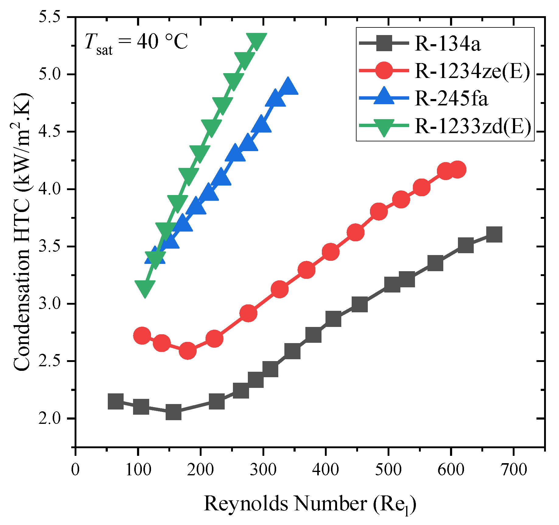
  • The condensing HTC of R-1234ze(Z) was approximately 10% higher than R-245fa.
  • The condensing HTC of R-1233zd(E) was comparable to that of R-245fa.
  • The condensing HTC of R-134a was approximately 2 times higher than R-1233zd(E).
  • The condensation HTCs of R-134a and R-1234yf were almost identical.
  • On smooth/enhanced inside tubes, the average condensation HTCs of the R-513A and R-1234ze(E) refrigerants were similar to R-134a at a lower mass flux (100~150 kg/m2s), while they were up to 10% higher than R-134a as the mass flux increased.
  • On smooth/enhanced inside tubes, the pressure drop of R-513A was similar to R-1234yf and 10% lower than that of R-134a at a higher mass flux. The R-1234ze(E) pressure drops were 20% higher compared to those of R-134a at a higher mass flux.
  • On a smooth tube, the film condensation HTCs of R-1234ze(E) and R-1233zd(E) were approximately 10.97% and 10.04% lower than those of R-134a.
  • In a minichannel, R-513A’s condensation HTCs were 2.6–25.6% lower than R-134a and the pressure drops were 4.5–14.0% lower than R-134a.
  • In a minichannel, R-450A’s HTCs were 2.4% higher than R-134a at higher mass fluxes and higher qualities but 11.7% lower than R-134a’s HTCs at lower mass fluxes. R450A’s pressure drop was comparable to R-134a’s pressure drop and it was 5.0% higher to 9.5% lower.
  • The saturation temperature has a negligible effect on condensation HTCs compared to refrigerant mass flux and vapor quality in the plate heat exchanger and outside the tube.
  • In plate heat exchanger, R-1234ze(E) exhibited lower (4% to 6%) HTCs and a 10% higher frictional pressure drop than those of R-134a.
  • The range of the film Reynolds numbers for R-1233zd(E) was smaller than that of R-1234ze(E) under similar surface-subcooling temperature conditions because the viscosity was approximately 70% larger, and the liquid film flow rate was about 20% lower for R-1233zd(E) than R-1234ze(E).

Author Contributions

Conceptualization, A.K. and C.-C.W.; Data collection and investigation, A.K.; Writing—original draft preparation, A.K.; Review, editing, and supervision, C.-C.W.; M.-R.C., C.-C.L. and K.-S.H. provided administration assistance. All authors have read and agreed to the published version of the manuscript.

Funding

The authors gratefully acknowledge the financial support from the Bureau of Energy of the National Science and Technology Council, Taiwan under the contract of 111-2221-E-A49 -090 -MY3. The financial support from the ministry of economic affairs of Taiwan is also appreciated.

Conflicts of Interest

The authors declare no conflict of interest.

References

  1. Lemmon, E.; Huber, M.; McLinden, M. REFPROP, NIST Standard Reference Database 23, v. 10.0; National Institute of Standards: Gaithersburg, MD, USA, 2018. [Google Scholar]
  2. El Kadi, K.; Alnaimat, F.; Sherif, S.A. Recent advances in condensation heat transfer in mini and micro channels: A comprehensive review. Appl. Therm. Eng. 2021, 197, 117412. [Google Scholar] [CrossRef]
  3. Fronk, B.M.; Garimella, S. In-tube condensation of zeotropic fluid mixtures: A review. Int. J. Refrig. 2013, 36, 534–561. [Google Scholar] [CrossRef]
  4. Ho, J.Y.; Leong, K.C. A critical review of filmwise natural and forced convection condensation on enhanced surfaces. Appl. Therm. Eng. 2021, 186, 116437. [Google Scholar] [CrossRef]
  5. Mauro, A.W.; Napoli, G.; Pelella, F.; Viscito, L. Flow pattern, condensation and boiling inside and outside smooth and enhanced surfaces of propane (R290). State of the art review. Int. J. Heat Mass Transf. 2021, 174, 121316. [Google Scholar] [CrossRef]
  6. Shon, B.H.; Jeon, S.W.; Kim, Y.; Kang, Y.T. Review: Condensation and Evaporation Characteristics of Low GWP Refrigerants in Plate Heat Exchangers. Int. J. Air-Cond. Refrig. 2016, 24, 1630004. [Google Scholar] [CrossRef]
  7. Tao, X.; Infante Ferreira, C.A. Heat transfer and frictional pressure drop during condensation in plate heat exchangers: Assessment of correlations and a new method. Int. J. Heat Mass Transf. 2019, 135, 996–1012. [Google Scholar] [CrossRef]
  8. Ko, J.-W.; Jeon, D.-S.; Kim, Y.-L.; Kim, S.-C. Experimental study on film condensation heat transfer characteristics of R1234ze(E) and R1233zd(E) over horizontal plain tubes. J. Mech. Sci. Technol. 2018, 32, 527–534. [Google Scholar] [CrossRef]
  9. Ko, J.-W.; Jeon, D.-S. Experimental study on film condensation heat transfer characteristics of R134a, R1234ze(E) and R1233zd(E) over condensation tube with enhanced surfaces. Heat Mass Transf. 2020, 56, 3001–3010. [Google Scholar] [CrossRef]
  10. Ji, W.-T.; Lu, X.-D.; Yu, Q.-N.; Zhao, C.-Y.; Zhang, H.; Tao, W.-Q. Film-wise condensation of R-134a, R-1234ze(E) and R-1233zd(E) outside the finned tubes with different fin thickness. Int. J. Heat Mass Transf. 2020, 146, 118829. [Google Scholar] [CrossRef]
  11. Park, K.-J.; Kang, D.G.; Jung, D. Condensation heat transfer coefficients of R1234yf on plain, low fin, and Turbo-C tubes. Int. J. Refrig. 2011, 34, 317–321. [Google Scholar] [CrossRef]
  12. Nagata, R.; Kondou, C.; Koyama, S. Comparative assessment of condensation and pool boiling heat transfer on horizontal plain single tubes for R1234ze(E), R1234ze(Z), and R1233zd(E). Int. J. Refrig. 2016, 63, 157–170. [Google Scholar] [CrossRef]
  13. Ji, W.-T.; Chong, G.-H.; Zhao, C.-Y.; Zhang, H.; Tao, W.-Q. Condensation heat transfer of R134a, R1234ze(E) and R290 on horizontal plain and enhanced titanium tubes. Int. J. Refrig. 2018, 93, 259–268. [Google Scholar] [CrossRef]
  14. Chen, T.; Wu, D. Enhancement in heat transfer during condensation of an HFO refrigerant on a horizontal tube with 3D fins. Int. J. Therm. Sci. 2018, 124, 318–326. [Google Scholar] [CrossRef]
  15. Jung, D.; Kim, C.-B.; Hwang, S.-M.; Kim, K.-K. Condensation heat transfer coefficients of R22, R407C, and R410A on a horizontal plain, low fin, and turbo-C tubes. Int. J. Refrig. 2003, 26, 485–491. [Google Scholar] [CrossRef]
  16. Reif, A.; Büchner, A.; Rehfeldt, S.; Klein, H. Outer heat transfer coefficient for condensation of pure components on single horizontal low-finned tubes. Heat Mass Transf. 2019, 55, 3–16. [Google Scholar] [CrossRef]
  17. Sajjan, S.K.; Dewangan, A.K.; Kumar, R.; Gupta, A. Experimental investigation and non-dimensional regression analysis of condensation heat transfer of R-600a over finned tubes. Int. J. Therm. Sci. 2021, 170, 107174. [Google Scholar] [CrossRef]
  18. Guo, Q.; Li, M.; Gu, H. Condensation heat transfer characteristics of low-GWP refrigerants in a smooth horizontal mini tube. Int. J. Heat Mass Transf. 2018, 126, 26–38. [Google Scholar] [CrossRef]
  19. Jacob, T.A.; Matty, E.P.; Fronk, B.M. Experimental investigation of in-tube condensation of low GWP refrigerant R450A using a fiber optic distributed temperature sensor. Int. J. Refrig. 2019, 103, 274–286. [Google Scholar] [CrossRef]
  20. Yang, C.-Y.; Nalbandian, H. Condensation heat transfer and pressure drop of refrigerants HFO-1234yf and HFC-134a in small circular tube. Int. J. Heat Mass Transf. 2018, 127, 218–227. [Google Scholar] [CrossRef]
  21. Hossain, M.A.; Onaka, Y.; Miyara, A. Experimental study on condensation heat transfer and pressure drop in horizontal smooth tube for R1234ze(E), R32 and R410A. Int. J. Refrig. 2012, 35, 927–938. [Google Scholar] [CrossRef]
  22. Wang, L.; Dang, C.; Hihara, E. Experimental study on condensation heat transfer and pressure drop of low GWP refrigerant HFO1234yf in a horizontal tube. Int. J. Refrig. 2012, 35, 1418–1429. [Google Scholar] [CrossRef]
  23. Wang, L.; Jiao, P.; Dang, C.; Hihara, E. Condensation heat transfer characteristics of R1234yf and other Refrigerants inside small-scale tube: An experimental study and heat transfer correlation development. Heat Mass Transf. 2022, 58, 1059–1074. [Google Scholar] [CrossRef]
  24. Longo, G.A.; Mancin, S.; Righetti, G.; Zilio, C. Saturated vapour condensation of HFC404A inside a 4mm ID horizontal smooth tube: Comparison with the long-term low GWP substitutes HC290 (Propane) and HC1270 (Propylene). Int. J. Heat Mass Transf. 2017, 108, 2088–2099. [Google Scholar] [CrossRef]
  25. Lips, S.; Meyer, J.P. Experimental study of convective condensation in an inclined smooth tube. Part I: Inclination effect on flow pattern and heat transfer coefficient. Int. J. Heat Mass Transf. 2012, 55, 395–404. [Google Scholar] [CrossRef]
  26. Lips, S.; Meyer, J.P. Experimental study of convective condensation in an inclined smooth tube. Part II: Inclination effect on pressure drops and void fractions. Int. J. Heat Mass Transf. 2012, 55, 405–412. [Google Scholar] [CrossRef]
  27. Agarwal, R.; Hrnjak, P. Condensation in two phase and desuperheating zone for R1234ze(E), R134a and R32 in horizontal smooth tubes. Int. J. Refrig. 2015, 50, 172–183. [Google Scholar] [CrossRef]
  28. Macdonald, M.; Garimella, S. Hydrocarbon condensation in horizontal smooth tubes: Part I—Measurements. Int. J. Heat Mass Transf. 2016, 93, 75–85. [Google Scholar] [CrossRef]
  29. Macdonald, M.; Garimella, S. Effect of Temperature Difference on In-Tube Condensation Heat Transfer Coefficients. J. Heat Transf. 2017, 139, 011502. [Google Scholar] [CrossRef]
  30. Jajja, S.A.; Nawaz, K.; Fricke, B.A. In Tube Condensation Heat Transfer and Pressure Drop for R454B and R32—Potential Replacements for R410A. Int. J. Refrig. 2022. [Google Scholar] [CrossRef]
  31. Lee, B.-M.; Gook, H.-H.; Lee, S.-B.; Lee, Y.-W.; Park, D.-H.; Kim, N.-H. Condensation heat transfer and pressure drop of low GWP R-404A alternative refrigerants (R-448A, R-449A, R-455A, R-454C) in a 5.6 mm inner diameter horizontal smooth tube. Int. J. Refrig. 2021, 128, 71–82. [Google Scholar] [CrossRef]
  32. Karageorgis, A.; Hinopoulos, G.; Kim, M.-H. A Comparative Study on the Condensation Heat Transfer of R-513A as an Alternative to R-134a. Machines 2021, 9, 114. [Google Scholar] [CrossRef]
  33. Diani, A.; Cavallini, A.; Rossetto, L. R1234yf condensation inside a 3.4 mm ID horizontal microfin tube. Int. J. Refrig. 2017, 75, 178–189. [Google Scholar] [CrossRef]
  34. Diani, A.; Brunello, P.; Rossetto, L. R513A condensation heat transfer inside tubes: Microfin tube vs. smooth tube. Int. J. Heat Mass Transf. 2020, 152, 119472. [Google Scholar] [CrossRef]
  35. Diani, A.; Campanale, M.; Rossetto, L. Experimental study on heat transfer condensation of R1234ze(E) and R134a inside a 4.0 mm OD horizontal microfin tube. Int. J. Heat Mass Transf. 2018, 126, 1316–1325. [Google Scholar] [CrossRef]
  36. Diani, A.; Campanale, M.; Cavallini, A.; Rossetto, L. Low GWP refrigerants condensation inside a 2.4 mm ID microfin tube. Int. J. Refrig. 2018, 86, 312–321. [Google Scholar] [CrossRef]
  37. Diani, A.; Rossetto, L. Condensation of an Azeotropic Mixture inside 2.5 mm ID Minitubes. Fluids 2020, 5, 171. [Google Scholar] [CrossRef]
  38. Hirose, M.; Jige, D.; Inoue, N. Optimum fin geometries on condensation heat transfer and pressure drop of R1234ze(E) in 4-mm outside diameter horizontal microfin tubes. Sci. Technol. Built Environ. 2019, 25, 1271–1280. [Google Scholar] [CrossRef]
  39. Lambrechts, A.; Liebenberg, L.; Bergles, A.E.; Meyer, J.P. Heat Transfer Performance During Condensation Inside Horizontal Smooth, Micro-Fin and Herringbone Tubes. J. Heat Transf. 2006, 128, 691–700. [Google Scholar] [CrossRef]
  40. Bashar, M.K.; Nakamura, K.; Kariya, K.; Miyara, A. Experimental Study of Condensation Heat Transfer and Pressure Drop inside a Small Diameter Microfin and Smooth Tube at Low Mass Flux Condition. Appl. Sci. 2018, 8, 2146. [Google Scholar] [CrossRef]
  41. Wen, J.; Gu, X.; Wang, S.; Li, Y.; Tu, J. The comparison of condensation heat transfer and frictional pressure drop of R1234ze(E), propane and R134a in a horizontal mini-channel. Int. J. Refrig. 2018, 92, 208–224. [Google Scholar] [CrossRef]
  42. Jige, D.; Mikajiri, N.; Nobunaga, M.; Inoue, N. Condensation heat transfer of pure refrigerants R1234yf and R32 inside multiple circular minichannels. Int. J. Heat Mass Transf. 2022, 195, 123146. [Google Scholar] [CrossRef]
  43. Jige, D.; Inoue, N.; Koyama, S. Condensation of refrigerants in a multiport tube with rectangular minichannels. Int. J. Refrig. 2016, 67, 202–213. [Google Scholar] [CrossRef]
  44. Goss, G.; Passos, J.C. Heat transfer during the condensation of R134a inside eight parallel microchannels. Int. J. Heat Mass Transf. 2013, 59, 9–19. [Google Scholar] [CrossRef]
  45. Morrow, J.A.; Derby, M.M. Flow condensation heat transfer and pressure drop of R134a alternative refrigerants R513A and R450A in 0.95-mm diameter minichannels. Int. J. Heat Mass Transf. 2022, 192, 122894. [Google Scholar] [CrossRef]
  46. Matkovic, M.; Cavallini, A.; Del Col, D.; Rossetto, L. Experimental study on condensation heat transfer inside a single circular minichannel. Int. J. Heat Mass Transf. 2009, 52, 2311–2323. [Google Scholar] [CrossRef]
  47. Del Col, D.; Azzolin, M.; Bortolin, S.; Zilio, C. Two-phase pressure drop and condensation heat transfer of R32/R1234ze(E) non-azeotropic mixtures inside a single microchannel. Sci. Technol. Built Environ. 2015, 21, 595–606. [Google Scholar] [CrossRef]
  48. Del Col, D.; Bortolato, M.; Azzolin, M.; Bortolin, S. Effect of inclination during condensation inside a square cross section minichannel. Int. J. Heat Mass Transf. 2014, 78, 760–777. [Google Scholar] [CrossRef]
  49. Azzolin, M.; Bortolin, S. Condensation and flow boiling heat transfer of a HFO/HFC binary mixture inside a minichannel. Int. J. Therm. Sci. 2021, 159, 106638. [Google Scholar] [CrossRef]
  50. Azzolin, M.; Berto, A.; Bortolin, S.; Moro, L.; Del Col, D. Condensation of ternary low GWP zeotropic mixtures inside channels. Int. J. Refrig. 2019, 103, 77–90. [Google Scholar] [CrossRef]
  51. Illán-Gómez, F.; López-Belchí, A.; García-Cascales, J.R.; Vera-García, F. Experimental two-phase heat transfer coefficient and frictional pressure drop inside mini-channels during condensation with R1234yf and R134a. Int. J. Refrig. 2015, 51, 12–23. [Google Scholar] [CrossRef]
  52. Gu, X.; Wen, J.; Wang, C.; Zhang, X.; Wang, S.; Tu, J. Condensation flow patterns and model assessment for R1234ze(E) in horizontal mini/macro-channels. Int. J. Therm. Sci. 2018, 134, 140–159. [Google Scholar] [CrossRef]
  53. Park, J.E.; Vakili-Farahani, F.; Consolini, L.; Thome, J.R. Experimental study on condensation heat transfer in vertical minichannels for new refrigerant R1234ze(E) versus R134a and R236fa. Exp. Therm. Fluid Sci. 2011, 35, 442–454. [Google Scholar] [CrossRef]
  54. Murphy, D.L.; Macdonald, M.P.; Mahvi, A.J.; Garimella, S. Condensation of propane in vertical minichannels. Int. J. Heat Mass Transf. 2019, 137, 1154–1166. [Google Scholar] [CrossRef]
  55. López-Belchí, A. Assessment of a mini-channel condenser at high ambient temperatures based on experimental measurements working with R134a, R513A and R1234yf. Appl. Therm. Eng. 2019, 155, 341–353. [Google Scholar] [CrossRef]
  56. López-Belchí, A.; Illán-Gómez, F.; Vera-García, F.; García-Cascales, J.R. Experimental condensing two-phase frictional pressure drop inside mini-channels. Comparisons and new model development. Int. J. Heat Mass Transf. 2014, 75, 581–591. [Google Scholar] [CrossRef]
  57. Liu, N.; Li, J. Experimental study on condensation heat transfer of R32, R152a and R22 in horizontal minichannels. Appl. Therm. Eng. 2015, 90, 763–773. [Google Scholar] [CrossRef]
  58. Liu, N.; Xiao, H.; Li, J. Experimental investigation of condensation heat transfer and pressure drop of propane, R1234ze(E) and R22 in minichannels. Appl. Therm. Eng. 2016, 102, 63–72. [Google Scholar] [CrossRef]
  59. Kruzel, M.; Bohdal, T.; Sikora, M. Heat transfer and pressure drop during refrigerants condensation in compact heat exchangers. Int. J. Heat Mass Transf. 2020, 161, 120283. [Google Scholar] [CrossRef]
  60. Liu, Y.; Wen, J.; Xu, P.; Khan, M.; Wang, S.; Tu, J. Numerical investigation on the condensation of R134a, R1234ze(E) and R450A in mini-channels. Int. J. Refrig. 2021, 130, 305–316. [Google Scholar] [CrossRef]
  61. Kuczyński, W.; Charun, H.; Piątkowski, P.; Bałasz, B.; Chliszcz, K. A regressive model for dynamic impulsive instabilities during the condensation of R134a, R1234ze(E) and R1234yf refrigerants. Int. J. Heat Mass Transf. 2021, 169, 120963. [Google Scholar] [CrossRef]
  62. Wang, H.S.; Rose, J.W. Theory of heat transfer during condensation in microchannels. Int. J. Heat Mass Transf. 2011, 54, 2525–2534. [Google Scholar] [CrossRef]
  63. Wang, H.S.; Rose, J.W. Film condensation in horizontal microchannels: Effect of channel shape. Int. J. Therm. Sci. 2006, 45, 1205–1212. [Google Scholar] [CrossRef]
  64. Wang, H.S.; Rose, J.W.; Honda, H. A Theoretical Model of Film Condensation in Square Section Horizontal Microchannels. Chem. Eng. Res. Des. 2004, 82, 430–434. [Google Scholar] [CrossRef]
  65. Awad, M.M.; Dalkiliç, A.S.; Wongwises, S. A Critical Review on Condensation Heat Transfer in Microchannels and Minichannels. J. Nanotechnol. Eng. Med. 2014, 5, 010904. [Google Scholar] [CrossRef]
  66. Kwon, O.J.; Shon, B.; Kang, Y.T. Experimental investigation on condensation heat transfer and pressure drop of a low GWP refrigerant R-1233zd(E) in a plate heat exchanger. Int. J. Heat Mass Transf. 2019, 131, 1009–1021. [Google Scholar] [CrossRef]
  67. Shon, B.H.; Jung, C.W.; Kwon, O.J.; Choi, C.K.; Tae Kang, Y. Characteristics on condensation heat transfer and pressure drop for a low GWP refrigerant in brazed plate heat exchanger. Int. J. Heat Mass Transf. 2018, 122, 1272–1282. [Google Scholar] [CrossRef]
  68. Jung, J.H.; Ko, Y.M.; Kang, Y.T. Condensation heat transfer characteristics and energy conversion performance analysis for low GWP refrigerants in plate heat exchangers. Int. J. Heat Mass Transf. 2021, 166, 120727. [Google Scholar] [CrossRef]
  69. Ko, Y.M.; Jung, J.H.; Sohn, S.; Song, C.H.; Kang, Y.T. Condensation heat transfer performance and integrated correlations of low GWP refrigerants in plate heat exchangers. Int. J. Heat Mass Transf. 2021, 177, 121519. [Google Scholar] [CrossRef]
  70. Zhang, J.; Kærn, M.R.; Ommen, T.; Elmegaard, B.; Haglind, F. Condensation heat transfer and pressure drop characteristics of R134a, R1234ze(E), R245fa and R1233zd(E) in a plate heat exchanger. Int. J. Heat Mass Transf. 2019, 128, 136–149. [Google Scholar] [CrossRef]
  71. Cattelan, G.; Diani, A.; Azzolin, M. Condensation heat transfer of R1234ze(E) and R134a inside a brazed plate heat exchanger: Experimental data and model assessment. Int. J. Refrig. 2022. [Google Scholar] [CrossRef]
  72. Kuo, W.S.; Lie, Y.M.; Hsieh, Y.Y.; Lin, T.F. Condensation heat transfer and pressure drop of refrigerant R-410A flow in a vertical plate heat exchanger. Int. J. Heat Mass Transf. 2005, 48, 5205–5220. [Google Scholar] [CrossRef]
  73. Yan, Y.-Y.; Lio, H.-C.; Lin, T.-F. Condensation heat transfer and pressure drop of refrigerant R-134a in a plate heat exchanger. Int. J. Heat Mass Transf. 1999, 42, 993–1006. [Google Scholar] [CrossRef]
  74. Soontarapiromsook, J.; Mahian, O.; Dalkilic, A.S.; Wongwises, S. Effect of surface roughness on the condensation of R-134a in vertical chevron gasketed plate heat exchangers. Exp. Therm. Fluid Sci. 2018, 91, 54–63. [Google Scholar] [CrossRef]
  75. Longo, G.A. Refrigerant R134a condensation heat transfer and pressure drop inside a small brazed plate heat exchanger. Int. J. Refrig. 2008, 31, 780–789. [Google Scholar] [CrossRef]
  76. Longo, G.A.; Zilio, C. Condensation of the low GWP refrigerant HFC1234yf inside a brazed plate heat exchanger. Int. J. Refrig. 2013, 36, 612–621. [Google Scholar] [CrossRef]
  77. Longo, G.A.; Zilio, C.; Righetti, G.; Brown, J.S. Condensation of the low GWP refrigerant HFO1234ze(E) inside a Brazed Plate Heat Exchanger. Int. J. Refrig. 2014, 38, 250–259. [Google Scholar] [CrossRef]
  78. Longo, G.A. Heat transfer and pressure drop during hydrocarbon refrigerant condensation inside a brazed plate heat exchanger. Int. J. Refrig. 2010, 33, 944–953. [Google Scholar] [CrossRef]
  79. Longo, G.A. The effect of vapour super-heating on hydrocarbon refrigerant condensation inside a brazed plate heat exchanger. Exp. Therm. Fluid Sci. 2011, 35, 978–985. [Google Scholar] [CrossRef]
  80. Longo, G.A. Heat transfer and pressure drop during HFC refrigerant saturated vapour condensation inside a brazed plate heat exchanger. Int. J. Heat Mass Transf. 2010, 53, 1079–1087. [Google Scholar] [CrossRef]
  81. Mancin, S.; Del Col, D.; Rossetto, L. Partial condensation of R407C and R410A refrigerants inside a plate heat exchanger. Exp. Therm. Fluid Sci. 2012, 36, 149–157. [Google Scholar] [CrossRef]
  82. Wang, R.; Kabelac, S. Condensation quasi-local heat transfer and frictional pressure drop of R1234ze(E) and R134a in a micro-structured plate heat exchanger. Appl. Therm. Eng. 2021, 197, 117404. [Google Scholar] [CrossRef]
  83. Khan, M.; Wen, J.; Shakoori, M.A.; Tao, W. Homogeneous condensation and thermophysical properties of R450A, R513A and R515A using molecular dynamics simulations. J. Mol. Liq. 2022, 353, 118795. [Google Scholar] [CrossRef]
  84. Pérez-García, V.; Méndez-Méndez, D.; Belman-Flores, J.M.; Rodríguez-Muñoz, J.L.; Montes-Rodríguez, J.J.; Ramírez-Minguela, J.J. Experimental study of influence of internal heat exchanger in a chest freezer using r-513a as replacement of r-134a. Appl. Therm. Eng. 2022, 204, 117969. [Google Scholar] [CrossRef]
  85. Devecioğlu, A.G.; Oruç, V. Improvement on the energy performance of a refrigeration system adapting a plate-type heat exchanger and low-GWP refrigerants as alternatives to R134a. Energy 2018, 155, 105–116. [Google Scholar] [CrossRef]
  86. Dobson, M.K.; Chato, J.C. Condensation in Smooth Horizontal Tubes. J. Heat Transf. 1998, 120, 193–213. [Google Scholar] [CrossRef]
Figure 1. The ideal characteristic of environmentally benign refrigerants.
Processes 10 01882 g001
Figure 2. Influence of tube diameter (smooth tube) on condensation HTC (Ko et al. [8]).
Processes 10 01882 g002
Figure 3. Condensation HTC of various low-GWP refrigerants alternative to R-134a on smooth tube. Rectangular, circular, and triangular upward solid connected line presents the Ko and Jeon [9] study, triangular downward solid connected lines present Ji et al. [10] study, star and triangular backward solid connected lines presents the Park et al. [11] study, remaining symbols presents the Nagata et al. [12] study.
Processes 10 01882 g003
Figure 4. Influence of FPI and knurling number on condensation HTC with R-134a, R-1234ze(E), and R-1233zd(E) Ko and Jeon [9].
Processes 10 01882 g004
Figure 5. Influence of fin thickness on condensation HTCs of R-134a, R-1234ze(E), and R-1233zd(E) Ji et al. [10].
Processes 10 01882 g005
Figure 6. Condensation heat transfer performance of R-134a, R-1234ze(E), and R-290 on smooth tube and titanium-enhanced tube Ji et al. [13].
Processes 10 01882 g006
Figure 7. Condensation heat transfer performance of R-134a and R-1234yf on the smooth, low-fin, and Turbo-C tube and R-1233zd(E) on the smooth and 3D tube. Rectangular and circular solid connected line presents the Chen and Wu [14] study and the remaining symbols present the Park et al. [11] study.
Processes 10 01882 g007
Figure 8. Condensation HTC of various refrigerants inside a 2 mm smooth tube. Triangular forward, hexagonal, and star solid connected line presents the Wang et al. [24] study, and the remaining symbols presents the Guo et al. [19] study.
Processes 10 01882 g008
Figure 9. Condensation HTC of various refrigerants inside the 4~5 mm smooth tube. Rectangular and circular solid connected line presents the Jacob et al. [19] study, triangular up and downward line presents the Yang and Nalbandian [20] study, star, triangular backward and forward solid connected lines present the Hossain et al. [21] study, hexagon, star, and pentagon solid connected lines present the Wang et al. [23,24] study, and remaining symbol presents the Longo et al. [25] study.
Processes 10 01882 g009
Figure 10. Condensation HTC of various refrigerants inside the smooth and microfin tube. Triangular backward solid connected line presents the Diani et al. [34], rectangular, triangular upward, and star solid connected line presents the Diani et al. [35], circular and triangular forward solid connected lines present the Diani and Rossetto [38] study.
Processes 10 01882 g010
Figure 11. Condensation HTCs of various refrigerants inside the minichannel. Rectangular, circular, and triangular upward solid connected line presents the Jige et al. [42] study, triangular downward solid connected lines present the Jige et al. [43] study, star, triangular backward and forward solid connected line presents the Morrow and Derby [45] study, circular cross and rectangular cross solid connected line presents the Matkovic et al. [47] study, and remaining symbols (circular plus and star) solid connected lines presents the Azzolin et al. [51] study.
Processes 10 01882 g011
Figure 12. Condensation HTC of low-GWP refrigerants inside the plate heat exchanger with different chevron angles. Rectangular and solid connected line presents the Known et al. [66] and Shon et al. [67] study respectively, triangular upward and downward solid connected lines presents the Jung et al. [68] study, star and triangular backward study presents the Ko et al. [69] study.
Processes 10 01882 g012
Figure 13. Pressure drops of low-GWP refrigerants inside the plate heat exchanger with different chevron angles. Rectangular and solid connected line presents the Known et al. [66] and Shon et al. [67] study respectively, triangular upward and downward solid connected lines presents the Jung et al. [68] study, star, and triangular backward solid connected line presents the Ko et al. [69] study.
Processes 10 01882 g013
Figure 14. Comparative condensation heat transfer performance of R-134a, R-1234ze(E), R-1233zd(E), and R-245fa inside the plate heat exchanger (Zhang et al. [70]).
Processes 10 01882 g014
Figure 15. Comparative pressure gradients of R-134a, R-1234ze(E), R-1233zd(E), and R-245fa inside the plate heat exchanger (Zhang et al. [70]).
Processes 10 01882 g015
Figure 16. Comparative condensation heat transfer performance of R-134a and R-410A inside the plate heat exchanger. Solid and rectangular solid connected line presents the Kuo et al. [73] and Yan et al. [74] study respectively.
Processes 10 01882 g016
Figure 17. Comparative pressure drops of R-134a and R-410A inside the plate heat exchanger. Solid and rectangular solid connected line presents the Kuo et al. [73] and Yan et al. [74] study respectively.
Processes 10 01882 g017
Figure 18. Condensation HTC of various refrigerants inside the plate heat exchanger. Rectangular, circular, and triangular upward solid connected lines present the Longo [75], Longo and Zilio [76] and Longo et al. [77] study respectively, triangular forward solid connected line presents the Longo [80] study, and the remaining symbols present the Longo [78] study.
Processes 10 01882 g018
Figure 19. Pressure drops of various refrigerants inside the plate heat exchanger. Rectangular, circular, and triangular upward solid connected lines present the Longo [75], Longo and Zilio [76] and Longo et al. [77] study respectively, triangular forward solid connected line presents the Longo [80] study, and the remaining symbols present the Longo [78] study.
Processes 10 01882 g019
Figure 20. Saturation temperature vs. liquid pressures of alternative refrigerants to R-134a [1].
Processes 10 01882 g020
Figure 21. Saturation temperature vs. latent heat of vaporization of alternatives to R-134a [1].
Processes 10 01882 g021
Figure 22. Saturation temperature versus surface tension of alternatives to R-134a [1].
Processes 10 01882 g022
Figure 23. Saturation temperature versus liquid to vapor thermal conductivity ratio of alternatives to R-134a [1].
Processes 10 01882 g023
Figure 24. Saturation temperature versus liquid to vapor viscosity ratio of alternatives to R-134a [1].
Processes 10 01882 g024
Figure 25. Saturation temperature versus vapor density of alternatives to R-134a [1].
Processes 10 01882 g025
Table 1. Thermodynamic and transport properties of low-GWP refrigerant alternatives to R-134a at 40 °C [1].
RefrigerantGWP100 YearsASHRAE Class M (g/mol) T c (°C) P a (kPa) P c (kPa) h fg (kJ/kg) ρ l (kg/m3) ρ v (kg/m3) μ l (μPa-s) μ v (μPa-s) k l (W/m.K) σ (N/m)
R-134a1300 *A1102.3101.081016.64059163.021146.750.085161.4512.3730.0747160.0061149
R-1234yf<1 *A2L114.0494.71018.43381132.271033.857.753127.2212.2470.0590450.0044031
R-513A 573 *A1108.496.51072.53766142.21073.257.716137.5112.2730.0645570.0048760
R-450A547 *A1108.6104.4901.743820156.641121.645.662156.7912.6980.0709760.0064315
R-1234ze(E)<1 *A2L114.04109.4766.53636154.81111.5140.64167.0012.930.0691870.006956
R-1234ze(Z)6 *A2L114.04150.1289.903530196.301183.414.126211.259.85800.0814980.010944
Low-pressure refrigerant alternative to R-123 and R-245fa
R-1233zd(E)1 *A1130.05165.5215.553570183.061225.611.665247.1410.8540.0782970.012618
R-12379 *B1152.93183.68154.473668164.941424.89.6292352.411.2600.0724210.013431
R-245fa858 *B1134.05154.01250.653650182.311296.714.012329.1310.9420.0832930.011711
* IPCC 5th assessment, GWP : global warming potential, M : molecular weight, T c : critical temperature, P a : absolute pressure, P c : critical pressure, h fg : latent heat of vaporization, ρ l : liquid density, ρ v : vapor density, μ l : liquid viscosity, μ v : vapor viscosity, k l : thermal conductivity, σ : surface tension.
Table 2. Dimensions/specifications of smooth/enhanced tube and experimental conditions reported in the literature.
AuthorsCondensation
Temperature (°C)
Working FluidCondensing Surface/Tube SpecificationsHeat Flux (kW/m2)Wall Subcool Δ T c (°C)
Ko et al. [8]36, 38, and 40R-1233zd(E) and R-1234ze(E)Smooth tube: D o = 19.05 mm, 15.87 mm, and 12.70 mm9 to 313 to 18
Ko and Jeon [9]38R-1233zd(E), R-1234ze(E), and R-134aSmooth tube: D o = 19.05 mm, L c = 1000 mm. Enhanced tube: D o , E 1 , E 2 , E 3 = 18.88 mm, fin height h fin , E 1 , E 2 , E 3 = 0.61 ± 0.05 mm, Knurling number: k n , E 1 = 85, k n , E 2 = 107, k n , E 3 = 117, fin per inch: FPI E 1 , E 2 = 55 ± 1, FPI E 3 = 60 ± 119 to 543 to 18
Ji et al. [10]36R-1233zd(E), R-1234ze(E), and R-134aSmooth tube: D o = 19.09 mm. Enhanced tube: T-C1 D o , T-C1 = 18.99 mm, h fin , o , T-C1 = 0.857 mm, h fin , i , T-C1 = 0.33 mm, ave. outside fin thickness t T-C1 = 0.131 mm, FPI T-C1 = 45. T-C2 D o , T-C2 = 19 mm h fin , o , T-C2 = 0.790 mm, h fin , i , T-C2 = 0.338 mm, t T-C2 = 0.240 mm, FPI T-C2 = 45.20 to 901-28
Park et al. [11]39R-1234yf and R-134aSmooth tube: D o = 19.05 mm. Enhanced tube: low-fin tube ( D o = 18.90 mm, h fin = 1.214 mm, t tip = 0.252 mm, t base = 0.576 mm, FPI = 26). Turbo-C tube ( D o = 18.90 mm, h fin = 0.760 mm, t tip = 0.250 mm, t base = 0.350 mm, FPI = 42)8 to 1223 to 8
Nagata et al. [12]20 to 60R-1233zd(E), R-1234ze(Z), R-1234ze(E), R-245fa, and R-134a Smooth tube: D o = 19.12 mm, L c = 400 mm, R a = 0.41 μm3 to 410.8 to 28.8
Ji et al. [13]35 and 40R-134a, R-1234ze(E), and R-290Smooth tube: D o = 15.99 mm. Enhanced tube: D o = 16.01 mm, D i = 14.87 mm, h fin , o = 0.300 mm, FPI = 33, t fin = 0.362 mm8 to 801.5 to 30
Chen and Wu [14]36.1R-1233zd(E)Smooth tube: D o = 25.4 mm, L c = 2500 mm. Enhanced 3D tube: D o = 25.27 mm, D i = 21.85 mm, wall thickness t = 0.635 mm, h fin , i = 0.35 mm, h fin , o = 0.95 mm, fin pitch = 0.55 mm5 to 1350.1 to 17
Jung et al. [15] 39R22, R407C, and R410ASmooth tune: D o = 19.05 mm. Enhanced tube: Low-fin tube ( D o = 18.90 mm, h fin = 1.214 mm, t tip = 0.252 mm, t base = 0.576 mm, FPI = 26). Turbo-C tube ( D o = 18.90 mm, h fin = 0.760 mm, t tip = 0.250 mm, t base = 0.350 mm, FPI = 42)5 to 1253 to 8
D o : outside diameter of the tube, FPI : fin per inch, k n : knurling number, t : thickness.
Table 3. Dimensions/specifications of minichannel/microfin tube and experimental conditions reported in the literature.
AuthorsRefrigerantChannel GeometryMass Flow Rate (kg/m2s)Condensing
Temperature (°C)
Guo et al. [18]R-1234ze(E), R-290, R-161 R-41, R-32, and R-134aSmooth tube: D i = 2 mm200 to 40035 to 40
Jacob et al. [19]R-134a and R-450ASmooth tube: D i = 4.7 mm100 to 55045 and 55
Yang and Nalbandian [20]R-1234yf and R-134aSmooth tube: D i = 4.00 mm, L c = 600 mm, roughness R a = 0.16 μm200 to 120015
Hossain et al. [21]R-1234ze(E), R-32, and R-410ASmooth tube: D i = 4.35 mm, L c = 3.6 m150 to 40035 and 40
Wang et al. [22,23]R-1234yf, R-134a, and R-32Smooth tube: D i = 4 mm and 2 mm, L c = 450 mm and 230 mm 100 to 40040, 45, and 50
Longo et al. [24]R-404A, R-290, and R-1270 Smooth tube: D i = 4 mm, L c = 800 mm, R a = 0.7 μm75 to 80030, 35, and 40
Lips and Meyer [25,26]R-134aSmooth tube: D i = 8.38 mm200 to 60040
Agarwal and Hrnjak [27]R-134a, R-1234ze(E), and R-32Smooth tube: D i = 8.38 mm100 to 30030 to 50
Macdonald and Garimella [28,29]R-290Smooth tube: D i = 7.75 and 14.45 mm150 to 45030 to 94
Jajja et al. [30]R-454B, R-32, and R-410ASmooth copper tube: D i = 7.90 mm100 to 20035 to 50
Lee et al. [31]R-448A, R-449A, R-455A, R-454C, and R-404ASmooth tube: D i = 5.6 mm80 to 40045
Karageorgis et al. [32]R-513A, R-1234yf, R-1234ze(E), and R-134aMicrofin tube: D i = 8.52 mm, D o = 9.52 mm, h fin = 0.25 mm, number of fins = 60, L c = 2 m, apex angle γ = 30°, helix angle φ = 15~30°100 to 44035
Diani et al. [33,34,35]R-1234yf, R-513A, R-1234ze(E), and R-134aSmooth tube: D i = 3.5 mm. Microfin tube: D i = 3.4 mm, number of fins = 40, h fin = 0.12 mm, γ = 43°, φ = 18°. 100 to 100030 and 40
Diani et al. [36]R-1234yf and R-1234ze(E)Microfin tube: D i = 2.4 mm, number of fins = 40, h fin = 0.12 mm, γ = 43°, φ = 7°300 to 100030 and 40
Diani and Rossetto [37]R-513ASmooth tube: D i = 2.5 mm. Microfin tube D i = 2.4 mm, number of fins = 40, h fin = 0.12 mm, γ = 43°, φ = 7°200 to 100030 and 40
Hirose et al. [38]R-1234ze(E)Smooth tube: D i = 3.48 mm. Microfin tube1: D i = 3.61 mm, number of fins = 40, h fin = 0.18 mm, γ = 13.7°, φ = 17°. Microfin tube2: D i = 3.56 mm, number of fins = 50, h fin = 0.13 mm, γ = 12.2°, φ = 25°. Microfin tube3: D i = 3.56 mm, number of fins = 50, h fin = 0.15 mm, γ = 12°, φ = 12°50 to 40035
Lambrechts et al. [39]R-22, R-134a, and R-407CSmooth tube: D i = 8.11 mm, L c = 1.5 m. Microfin tube: D i = 8.936 mm, L c = 0.9 m, h fin = 0.198–0.219 mm, number of fins = 60, γ = 55°, φ = 18°. Herringbone tube: D i = 8.52 mm, L c = 563 mm, h fin = 0.2 mm, number of fins = 70, apex angle γ = 25°, helix angle φ = 16°300 to 80040
Bashar et al. [40]R-134aSmooth tube: D i = 2.14 mm. Microfin tube D i = 2.17 mm, number of fins = 25, h fin = 0.10 mm, γ = 31°, φ = 10°50 to 30020 to 30
Wen et al. [41]R-1234ze(E) and R-134aSmooth tube D i = 1 mm400 to 80040
Jige et al. [42]R-1234yf and R-32Minichannels: D i = 0.49 mm, number of channels = 16, and D i = 0.81 mm, number of channels = 1250 to 40040
Jige et al. [43]R-134a, R-32, R-1234ze(E), and R-410ARectangular minichannels: D h = 0.76, 0.85, and 1.06 mm, L c = 600 mm, number of channels = 17100 to 40040 and 60
Goss et al. [44]R-134aMinichannel: D i = 0.77 mm230 to 44530 to 40
Morrow and Derby [45]R-134a, R-513A, and R-450AMinichannel: D i = 0.95 mm200 to 50040
Matkovic et al. [46]R-134a and R-32Minichannel: D i = 0.96 mm100 to 120040
Col et al. [47]R32/R1234ze(E) non-azeotropic mixturesMinichannel: D i = 0.96 mm, R a = 1.3 μm150 to 80040
Col et al. [48]R-134a and R-32Square channel D h = 1.23 mm100 to 39040
Azzolin and Bortolin [49]R-32 and R-1234ze(E) (0.75/0.25)Minichannel: D i = 0.96 mm, R a = 1.3 μm150 to 80041.5
Azzolin et al. [50]R-455A and R-452B Minichannel: D i = 0.96 mm. Conventional tube: D i = 8 mm 200 to 800 40
Gomez et al. [51]R-1234yf and R-134aMinichannel: D i = 1.16 mm, R a = 0.226 μm350 to 940 25 to 55
Gu et al. [52]R-1234ze(E) and R-134aMini-/macrochannels: D i = 0.493 to 4.57 mm400 to 80040
Park et al. [53]R-1234ze(E), R-134a, and R-236faVertical multiport rectangular minichannel: D h = 1.45 mm50 to 26025 to 70
Murphy et al. [54]R-290Vertical minichannel: D i = 1.93 mm75 to 15047 and 74
Belchí [55]R-134a, R-513A, and R1234yfMinichannel: square D h = 1.16 mm, R a = 0.226, triangular D h = 0.71 mm, R a = 0.262200 to 100040 to 60
Belchí et al. [56]R-1234yf, R-134a, and R-32Minichannel: square D h = 1.16 mm, R a = 0.226350 to 94020 to 55
Liu and Li [57]R-32, R-152a, and R-22Circular minichannel: D i = 1.152 mm. Square minichannel: D h = 0.952 and 1.304 mm200 to 80030 to 50
Liu et al. [58]R-1234ze(E), R-290, and R-22Circular minichannel: D i = 1.085 mm. Square minichannel: D h = 0.952200 to 80040 and 50
Kruzel et al. [59]R-134a, R-404A, R-407C, and R-410AMicrochannel/minichannel: D i = 0.5, 0.64, 0.7, 1.2, 1.6, 2.0, and 2.5 mm100 to 200035 to 50
Liu et al. [60]R134a, R-1234ze(E), and R-450AMinichannel: D i = 1 mm and 2 mm400 to 80040
Kuczynski et al. [61]R-1234yf, R-1234ze(E), and R-134aSmooth tube: D i = 3.30, 2.30, 1.92, 1.44, and 1.40 mm, L c = 1000 mm60 to 36120 to 55
D i : inside diameter, D h : hydraulic diameter; L c : condensation length, γ : apex angle, φ : helix angle, h fin : fin height, R a : surface roughness.
Table 4. Dimensions/specifications of the plate heat exchanger and experimental conditions reported in the literature.
Authors Working FluidCondensing Temperature (°C)Mass Flux (kg/m2s)Heat Flux (kW/m2)Plate Heat Exchanger Geometry
Known et al. [66]R-1233zd(E)37.7 to 50.813 to 23.82.5 to 4.5Port-to-port length: L = 234 mm, plate length: L plate = 287 mm, plate width: w = 117 mm, area of the plate: A = 0.0274 m2, enlargement factor: ϕ = 1.15, corrugation/chevron angle: β = 60°, average spacing between two plates: b = 1.94 mm, corrugation pitch: λ = 7.5 mm, refrigerant side channel: N r = 2, water side channel: N w = 3, port diameter: D p = 19.05 mm, plate material: stainless steel, plate thickness: t = 0.4 mm
Shon et al. [67]R-1233zd(E)37.7 to 50.813.0 to 23.82.5 to 4.5Same geometry as mentioned in reference [66]
Jung et al. [68]R-1234ze(E) and R-1233zd(E)37.7 to 50.7 13 to 23.81.5 to 4.5Same geometry as mentioned in reference [66], β = 60° and 30°
Ko et al. [69]R-12430 to 50 16 to 26 2.5 to 4.5Same geometry as mentioned in reference [66]
Zhang et al. [70]R-1234ze(E), R134a, R-245fa, and R-1233zd(E) 29.7 to 71.016 to 904 to 57.4 L = 278 mm, L plate = 317 mm, w = 76 mm, β = 65°, b = 1 mm, λ = 7 mm, N r = 2, N w = 3, D p = 18 mm, D h = 3.4 mm
Cattelan et al. [71]R-1234ze(E) and R-134a34.6 and 42.39 to 49 - L plate = 464.2 mm, w = 117 mm, ϕ = 1.22, β = 60°, b = 1.46 mm, λ = 7.5 mm, N r = 2, N w = 3, D p = 19.05 mm, plate material: stainless steel, t = 0.4 mm
Kuo et al. [72]R-410A2050 to 150 5 to 20 L = 450 mm, L plate = 500 mm, w = 120 mm, β = 60°, w p = 70 mm b = 3.3 mm, λ = 10 mm, D p = 25 mm, plate material: SS-316, plate thickness: t = 0.4 mm
Yan et al. [73]R-134a26.7 to 35.560 to 12010 to 16 Same geometry as mentioned in reference [72]
Soontarapiromsook et al. [74]R-134a40 to 50 61 to 895 to 15 L = 360 mm, w p = 70 mm, β = 65°, b = 2.5 mm, D p = 32 mm, plate material: SS-316, t = 0.6 mm, plate roughness: R a = 0.594 to 2.754 μm
Longo et al. [75,76,77]R-134a, R-1234ze(E), and R-1234yf24.6 to 40.211.6 to 41.36.2 to 28.1 L = 278 mm, L plate = 310 mm, w = 72 mm, A = 0.02 m2, ϕ = 1.24, β = 65°, b = 2 mm, λ = 8 mm, N r = 4, N w = 5, number of heat transfer plates: N h = 8, R a = 0.4 μm
Longo et al. [78,79] R-600a, R-290, and R-127024.8 to 40.35.3 to 41.45.2 to 34.4Same geometry as mentioned in reference [75]
Longo et al. [80]R-236fa, R-134a, and R-410A24.7 to 40.211.2 to 41.46.2 to 34.4Same geometry as mentioned in reference [75]
Mancin et al. [81]R-407C and R-410A41.815 to 40- L = 526 mm, w = 111 mm, number of plates: N p = 6, N r = 2, N w = 3, number of heat transfer plates: N h = 4, plate material: stainless steel
Wang and Kabelac [82]R1234ze(E) and R134a22.51 to 40.8434.08 to 70.649.95 to 24.3 L = 1090 mm, L plate = 720 mm, w = 486 mm, ϕ = 1.159, β = (27° + 63°)/2, b = 3.2 mm, λ = 12 mm, N p = 10, D p = 155 mm, plate material: SS-316, t = 0.6 mm
Publisher’s Note: MDPI stays neutral with regard to jurisdictional claims in published maps and institutional affiliations.

