Article

Custom-Shaped Carbon Xerogel Materials by 3D Printing

by
Cédric Wolfs
1,
Stéphanie D. Lambert
1,
Alexandre F. Léonard
2 and
Julien G. Mahy
1,*
1
Department of Chemical Engineering—Nanomaterials, Catalysis & Electrochemistry, University of Liège, B6a, Quartier Agora, Allée du six Août 11, 4000 Liège, Belgium
2
Department of Chemical Engineering—CARPOR, University of Liège, B6a, Quartier Agora, Allée du six Août 11, 4000 Liège, Belgium
*
Author to whom correspondence should be addressed.
Processes 2022, 10(10), 1979; https://doi.org/10.3390/pr10101979
Submission received: 31 August 2022 / Revised: 23 September 2022 / Accepted: 27 September 2022 / Published: 1 October 2022
(This article belongs to the Special Issue Advances in Sol-Gel Processes)

Abstract

:
Sol–gel-based carbon xerogels possess very promising properties for pollution abatement, using processes that associate adsorption and on-site electrochemical oxidation. However, combining a high exterior surface area (for efficient diffusion) and a monolithic shape (necessary for electrochemical processes) poses challenges. In this work, the shape of monolithic carbon xerogels was contrived by the use of 3D-printed molds. Several parameters were optimized: the choice of mold design, the choice of plastic, the 3D printer parameters, the solvent, and the process of dissolving the plastic. A design combining fine sticks and plates made of ABS was printed; a sol–gel carbon xerogel monolith was synthesized in it, and the mold was removed by using a combination of acetone and pyrolysis. Dissolving the plastic could be carried out by placing the material on a metallic net and leaving the dissolved ABS to settle. The resulting carbon material exhibits a high exterior surface area and good strength, leading to potential uses in the aforementioned process. The research shows that 3D printing is an efficient method of parameter optimization in pre-industrialization research, thanks to its flexibility, low cost, and ease of use.

1. Introduction

Adsorption on highly porous materials has proven very effective for pollutant removal [1]. Indeed, the adsorption process has been found to be superior to other technologies in terms of initial costs, simplicity of design, operation, and insensitivity to toxic substrates [1,2]. Specifically, activated carbons (ACs) are the most widely used, and with great success because of their high adsorption capacity [1], demonstrated for a large number of pollutants of various nature and properties [1,3,4]. In this context, porous carbon materials with high specific surface area and large pore volume with well-controlled morphology are interesting to further improve the process by decreasing mass transport issues. For instance, carbon xerogels (CXs), obtained by polycondensation of resorcinol and formaldehyde in water (solvent) in presence of a basification agent, are excellent adsorption materials as both the meso-/macropore and the micropore texture can be modulated by adjusting the synthesis parameters and by CO2 or water vapor [1,5,6,7] to reach high specific surface area (up to 2000 m2/g). One advantage of carbon xerogel is that it can be molded easily to produce a large range of shapes depending on the application or the configuration of the process.
A straightforward way of molding various shapes is to use 3D printing. Additive manufacturing has been evolving for numerous years to tailor specific structures [8,9,10,11,12]. A benefit of 3D printing is the creation of complex geometries. Low production volumes can be manufactured cost-effectively, which reduces investment in tooling, for example. Iterating the process of creating new geometries and creating the corresponding parts can be achieved in a flexible and fast manner with 3D printing.
The additive manufacturing technique that can be applied to produce molds for carbon materials’ shaping is material extrusion. Material extrusion is a form of 3D printing that utilizes thermoplastic filaments to create parts. This process dispenses material through a nozzle onto a build platform where the material solidifies. The nozzle moves along the build platform while dispensing material to obtain the desired shape. Furthermore, when required, there is a possibility to print a mold with dissolvable material. Depending on the supporting material, it can be mechanically removed or it can be dissolved in either water or an organic solvent [8].
In this paper, the macroscopic geometry of sol–gel carbon xerogels will be tailored by using 3D printing to produce specific molds. The best raw materials for molds will be studied and chosen to be compatible with xerogel production. The main parameters for selection are detailed in Section 2.3. After material selection, the design of the mold and determination of the ideal parameters of the 3D printer will be solved. Finally, methods to remove the mold without breaking the carbon material will be studied.

2. Materials and Methods

2.1. Preparation of Carbon precursor Solution

1.725 mol of resorcinol (ACS reagent, ≥99.0%, Merck, Kenilworth, NJ, USA) was dissolved in 20 mol of H2O under stirring. After a few minutes, the resorcinol was dissolved. Then, a solution containing 3.45 mol formaldehyde (ACS reagent, 37 wt. % in H2O, contains 10–15% methanol as a stabilizer, Sigma-Aldrich, St. Louis, MO, USA), 8.24 mol H2O and 0.87 mol methanol (ACS reagent, ≥99.8%, Merck) was added to the resorcinol solution [13,14,15]. Finally, the pH was increased by adding an amount C (mol) of Na2CO3 powder (powder, ≥99.5%, ACS reagent, Sigma-Aldrich). This quantity C was set by determining the molar ratio R/C, where R was the quantity of resorcinol, i.e., 1.725 mol. The ratio R/C was set to different values to control the texture of the material. When the Na2CO3 was dissolved, the solution was ready to be poured into vessels [5,6,13,14,15].

2.2. Preparation of Custom-Shaped Carbon Monoliths Using a 3D-Printed Mold

Custom-shaped monoliths were prepared by pouring the synthesis product described in Section 2.1 into a 3D-printed plastic mold. The assembly (of plastic and carbon xerogel) was then heated at 85 °C for 72 h inside a sealed glass container. In this container, a small quantity of the sol was poured into a small disposable Petri dish next to the mold–carbon assemblies. The goal of this operation was to saturate the atmosphere inside the container with the components of the sol so that no unwanted evaporation took place, and the stoichiometry of the samples was kept constant.
After that, the container was cooled down to room temperature. At that moment, condensation should have occurred inside the container where the curing took place; if it was not the case, the container was not properly sealed, releasing toxic fumes and compromising the stoichiometry of the sol.
The condensed liquid was properly disposed of, and the glass container was scraped and cleaned. The molds were then also scraped on the outside. Then, they were completely dipped in an acetone container that was gently stirred.
After this gelation step, the molds contained a brownish solid. The solids were removed from the molds (see Section 2.3) and placed in a vacuum oven at 60 °C, and the pressure program was the following: start at 900 mbar for 45 min, a decrease in pressure by 100 mbar every 45 min. After the 100 mbar stage, the pressure was decreased down to 20 mbar and the temperature was set at 150 °C for 24 h.
Finally, the gel was placed in a tubular furnace under a weak N2 flux to undergo pyrolysis.
The following temperature profile was used: (1) ramp at 1.7 °C/min to 150 °C and hold for 15 min; (2) ramp at 5 °C/min to 400 °C and hold for 60 min; (3) ramp at 5 °C/min to 800°C and hold for 120 min; and (4) natural cooling to room temperature.
When the material was removed from the furnace, it was matte to slightly shiny black and had shrunk.
The choice of the mold design, material, the corresponding solvent, and the conditions in which the molds were dissolved are all justified in the following sections.

2.3. Selection of Plastic as the Mold’s Raw Material

All operations were carried out on a Prusa i3 Mk3S printer. Different types of plastics were considered as potential candidates for the mold’s raw material. They were evaluated based on the following requirements:
The material:
  • Has to withstand a temperature of 85 °C for 72 h;
  • Must be chemically inert towards the reagents in the XC synthesis (namely water, formaldehyde, Na2CO3, and resorcinol);
  • Must be able to be dissolved or removed via a liquid (other than formaldehyde and water).
  • If more than one type of material can fit all the previous criteria, then cost (of the plastic and the corresponding solvent), printability of the plastic, mechanical properties of the plastic, and ecological/health impact of the solvent will be used to make a choice.
The first criterion corresponds to the glass transition temperature (Tg) [16], which must be at least higher than 85 °C for thermoplastics. If Tg is unknown, or close to 85 °C, the plastic can be manually tested for stiffness at that temperature.
Again, the second criterion can usually be found by inspecting the literature. If this is not the case, the inertness can be determined experimentally.
The third criterion was assessed by reviewing the literature first, to limit the number of tests. Combinations were considered possible when either (i) mentions of the plastic dissolving in the corresponding solvent were found or (ii) chemical resistance charts hinted at a poor resistance of the plastic to the solvent. For possible plastic/solvent combinations, 100 mg of the plastic was dissolved in 5 mL of the corresponding solvents. Each test tube containing the solvent and the plastic sample was sealed, mixed using a vortex stirrer for 15 s, and left for 24 h. The test was considered successful if no solid residue was detected at the end of the test. This could be checked by pouring the content of the test tube onto a sieve. In that case, increments of 100 mg were added until a solid residue was detected or until 500 mg were completely dissolved (which corresponds to the sufficient solubility of 100 g/L).
The fourth criterion is divided into five parts: (i) cost of the plastic; (ii) printability, which mostly relates to warping problems and quality of the print; (iii) mechanical properties, including the coefficient of thermal expansion and Young’s modulus; (iv) price of the solvent; and (v) ecological/health impact of the solvent, which will be detailed below. The cost of the plastic (i) was assessed by checking the purchasing costs of 1 kg of each considered polymer, as filament rolls, from the company RS Components. This was carried out on 1 October 2020 from the UK store, with the prices in pounds converted into euros according to the exchange rate of that day (GBP 1 = EUR 1.1). For solvents (iv), the same was carried out by checking the Sigma-Aldrich shop. In both cases, if several conditionings were proposed, the largest conditioning was selected to decrease the price. Each plastic was attributed a subjective note (such as ”good” or ”poor”) for printability (ii) based on personal experience and consensus from 3D-printing users and manufacturers. The coefficient of thermal expansion (iii) is important during both the printing step and the transformation of the sol into a gel. The part could also be strained so that the final material’s dimensions might vary. This is where Young’s modulus intervenes. The ecological and health impacts of the solvent were judged based on MSDS (material safety data sheets). Regarding the environment, hazardous substances are often part of the US’s Clean Air Act and/or Clean Water Act. European risk phrases (e.g., ”R36-irritating to eyes”) are also a source of information regarding the danger of the substances.

2.4. Design of the Mold and Determination of Ideal Parameters of the 3D Printer

To design the mold, several objectives had to be reached.
  • The space to be filled by the sol (i.e., the negative of the mold) must have a geometry where diffusion from the outside was as fast as possible. This is intended to speed up the diffusion of adsorbents into the finished material during the final application.
  • The parts had to be printable consistently, with the design of the mold limiting the possible defects.
  • The design of the plastic mold must not induce mechanical weaknesses.
  • The combination of parts had to constitute an airtight set, from where the sol’s evaporation should be limited as much as possible.
  • The mold had to be easily wettable, i.e., the sol should be easily poured (or forced) into the mold.
A trial-and-error approach was used to address these challenges. Several iterations of possible molds will be presented in the results part (Section 3.2 and Section 3.3), with the shortcomings of each iteration corrected in the next one. This process was stopped as soon as the design was satisfactory, and that good-quality carbon xerogel samples were obtained.
As for 3D-printing parameters, a similar method was employed, starting with default parameters proposed for the selected plastic in PrusaSlicer13. Several important parameters were varied to address arising problems, to increase the quality of the printed piece, and to make the process quicker. These are detailed in Section 3.3.

2.5. Method of Removal of the Mold

Several processes to remove the mold were attempted. Again, the performance of each process was assessed qualitatively, based on the quality of the final result and the practicality of the process. The attempts were the following:
(i)
Pyrolyze the mold (using the method described previously).
(ii)
Dissolve the mold by putting it in 600 mL of the selected solvent, dispose of it after one day, and replace it with new solvent until the plastic is fully dissolved. When not much plastic is left, the process is aided by sonication. During the dissolution, there can be either:
(a)
No stirring;
(b)
Mild stirring;
(c)
Strong stirring;
(d)
Or mild stirring with the sample captured in a metallic net.
(iii)
A combination of dissolution and pyrolysis, as explained by the following modus operandi. Dissolve the mold by putting it in 600 mL of the selected solvent, dispose of it after one day, and replace it with new solvent until the plastic is mostly dissolved, i.e., when the outermost surface of the carbon xerogel is completely visible and when the solvent is not opaque after 24 h in contact with the carbon–plastic assembly. Afterward, the material and the leftover plastic are pyrolyzed in the same manner as previously described. The sonication and agitation conditions are the same as in the previous step.

3. Results

3.1. Selection of Plastic as the Mold’s Raw Material

The plastics were considered based on their availability as 3D printing rolls. The following were initially selected: ABS, ASA, PETG, PLA, HIPS, PVA, and PP. Other plastics exist but are less usual, or not adapted to our particular application. For instance, carbon-filled, wood-filled and metal-filled plastics are printable, but offer nothing but complications; the hygroscopic and quite flexible [17] Nylon (or polyamide) will not be considered a possible candidate either.

3.1.1. First Criterion: Glass Transition Temperature

Applying the first criterion (related to Tg, Table 1), PLA must be eliminated. Indeed, its mechanical properties are largely insufficient at that temperature, with Young’s modulus below 10 MPa at 85 °C compared to 2000 MPa at 25 °C [18]. While PETG, PVA, and PP are not to be preferred, they will not be rejected yet, as their Tg is relatively close to 85 °C, and their mechanical properties will not necessarily be disastrous at that temperature. The case of PP is particular as it is typically used past its Tg. Anyway, several sources [19,20] recommend a maximum operating temperature of 80 °C so that it is unclear whether it is practical to use it at 85 °C.
Finally, ABS, ASA, and HIPS all have glass transition temperatures above the 85 °C target, which make them the preferred candidates at this stage.

3.1.2. Second Criterion: Chemical Resistance

In Table 2, one can observe that virtually all plastics are resistant to both liquids used in our synthesis, thus filling our second criterion. The mildly basic conditions are not a problem for most plastics either. The only exception is PVA, a polymer made to be water-soluble. Of course, since the synthesis is water-based, PVA has to be rejected.
HIPS and ASA are not studied as extensively as other plastics. As their resistance data are lacking, they will not be rejected; they can be tested in practical conditions if they fit the remaining criteria.

3.1.3. Third Criterion: Ability to Be Dissolved

The third criterion, related to whether the polymer can be dissolved, is easily checked for a few of the remaining polymers: indeed, ABS and ASA parts are frequently finished by smoothing them with acetone vapor [34]. This process is caused by dissolving both polymers in this solvent, as intended. HIPS can readily be dissolved by d-limonene, making it a typical choice to support complex 3D-printed ABS parts [30]. Polypropylene can be dissolved in trichlorobenzene and dichloromethane at 160 °C [35]. Its isotactic variant can also be dissolved in decalin at 90 °C, or xylene at 99 °C [36]. These temperatures, however, are impractical and energy-consuming. Finally, PETG’s chemical resistance is praised by several sources, and no convincing information about a suitable solvent was found in the literature.

3.1.4. Comparison of Remaining Candidates

Table 3 compares different characteristics of the five remaining candidates. A glance at mechanical properties shows that similar values are obtained across Table 3, except for PP’s relatively low Young’s modulus. The coefficients of thermal expansion hover around 104, with ABS having the highest value. However, comparing mechanical features does not appear to be a good method of discrimination.
Printability is relatively bad for all polymers, except some of those which were already excluded (PETG, PLA). Thus, the chosen plastic will require some tuning to print good quality parts. The only remaining criterion is the cost. Among the remaining materials, ABS is the cheapest, followed by HIPS. However, one must take the cost of the corresponding solvent into account as well.
Table 4 shows the characteristics of possible chemicals able to dissolve selected plastics (based on literature and laboratory trials).
In addition, several considerations must be made regarding ecological impacts and human health impacts. Acetone and ethyl acetate are relatively safe if handled correctly, with the risk phrases R36, R66, and R6716. d-limonene is only irritating to the skin (R38, R43), and thus also relatively safe. Dichloromethane is highly volatile, has no smell, and can cause serious conditions such as coma if inhaled or ingested. Trichloromethane and nitrobenzene are even worse, being a reported cause of death and collecting various risk phrases related to health (trichloromethane: R22, R38, R40, and R48; nitrobenzene: R23, R24, R25, R40, R48, and R62). Regarding the environment, neither acetone, ethyl acetate nor d-limonene appears in the Clean Water Act or Clean Air Act, but d-limonene is listed as very toxic to aquatic environments by the EU (R50, R53). The three other chemicals are all hazardous for either water or air, or both. Only nitrobenzene, however, collects the R51 and R53 labels regarding aquatic toxicity.
In summary (Table 5), it is observed that three plastics were rejected for various reasons: PLA cannot resist at 85 °C, PVA is soluble in water, and PETG cannot be dissolved. Among the four other plastics, PP is underperforming in most criteria and is not going to be selected. HIPS is the easiest to dissolve, but the cost of its solvent (d-limonene) is prohibitive. Indeed, it is about 7 times more expensive than acetone and almost 10 times more expensive than dichloromethane. Finally, between ABS and ASA, the differences are small. They are both dissolved by acetone (which is a cheap and safe solvent). Their characteristics are mostly similar. Both are moderately hard to print, with similar warping problems, and both release toxic fumes because of the presence of styrene (although the problem is easily circumvented by ventilating correctly). The only thing that sets them apart is the cost: ASA is 57% more expensive than ABS. For this reason, ABS will be the choice for the rest of this study, although ASA and HIPS would have been reasonable possibilities.

3.2. Design of the Mold

In 
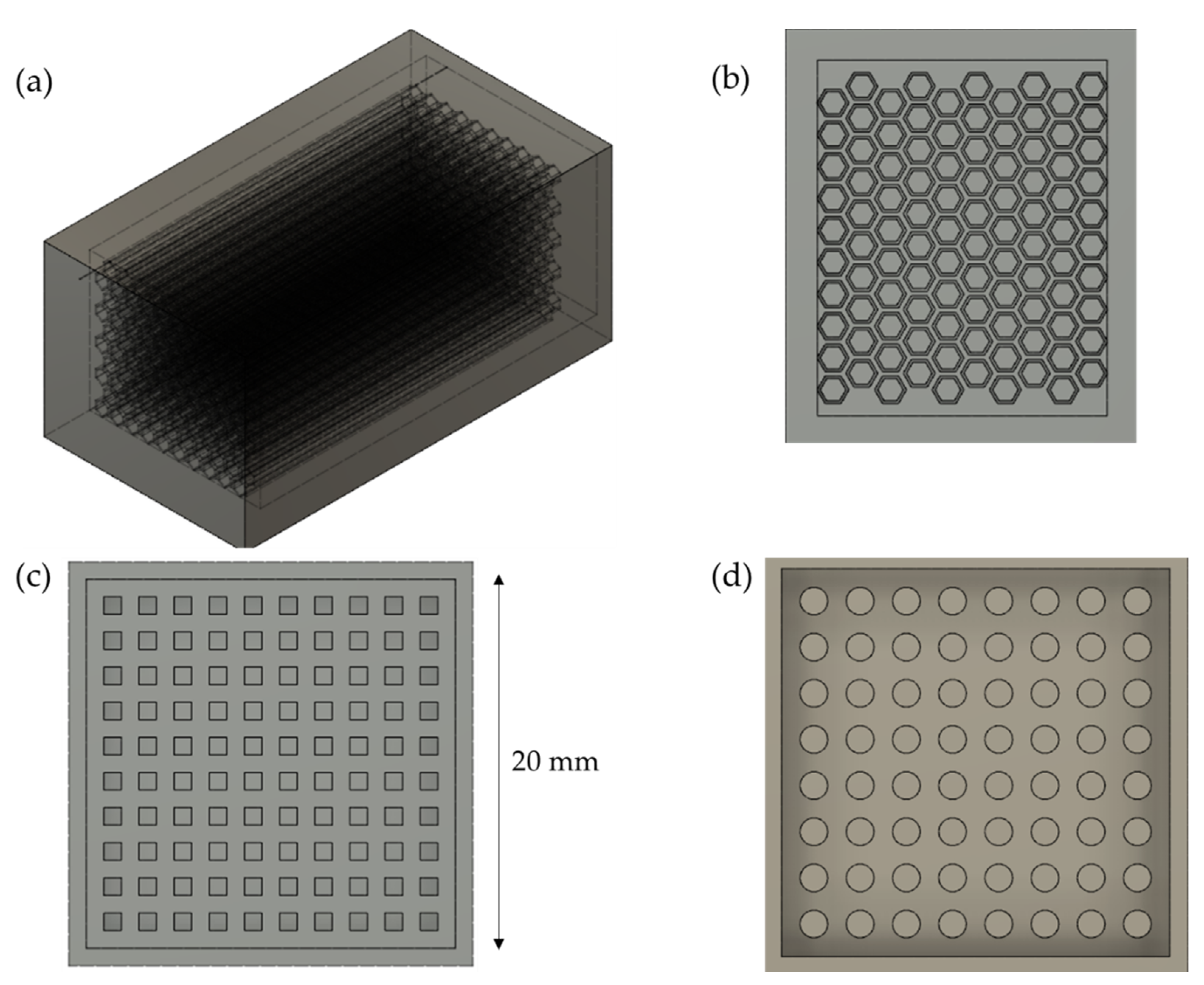
Figure 1a, the first attempt at designing the mold is represented. This type of object leads to prismatic holes of different shapes at their base. The holes are to be filled with a syringe, as their sizes are too small to allow the liquid to flow freely inside them if the liquid is simply poured onto it. After gelation, the prismatic rods are connected via a rectangular base, which is formed at the top of the object, filling the gap between the extremities of the prismatic shapes and the extremity of the object. After attempting to print stick design 1, two problems appeared: (i) the distance between two hexagons (80 μm) was slightly too fine for the printer, and (ii) printing thin walls vertically over a large height (12 mm) leads to misprints. Indeed, warping causes the position of the object to shift slightly during the course of printing, so that thin walls are not perfectly vertical. The object is then unusable. Stick designs 2 and 3 solve that problem by increasing the distance between the geometric objects, making the printing process easier, less sensitive to warping, and more mechanically solid. Both designs print correctly and reliably. Of course, they have the disadvantage of leaving less space for the carbon object, use more plastic, and are longer to print. However, the carbon objects resulting from this design have a decisive drawback: because of the very large aspect ratio of the square or circular prisms, the rods are loosely fixed on the base and break easily. The resulting object is too delicate and cannot be used in practical applications. Furthermore, even for smaller aspect ratios, the process of filling the mold with a sol is not straightforward, as surface tension prevents the liquid from flowing freely.
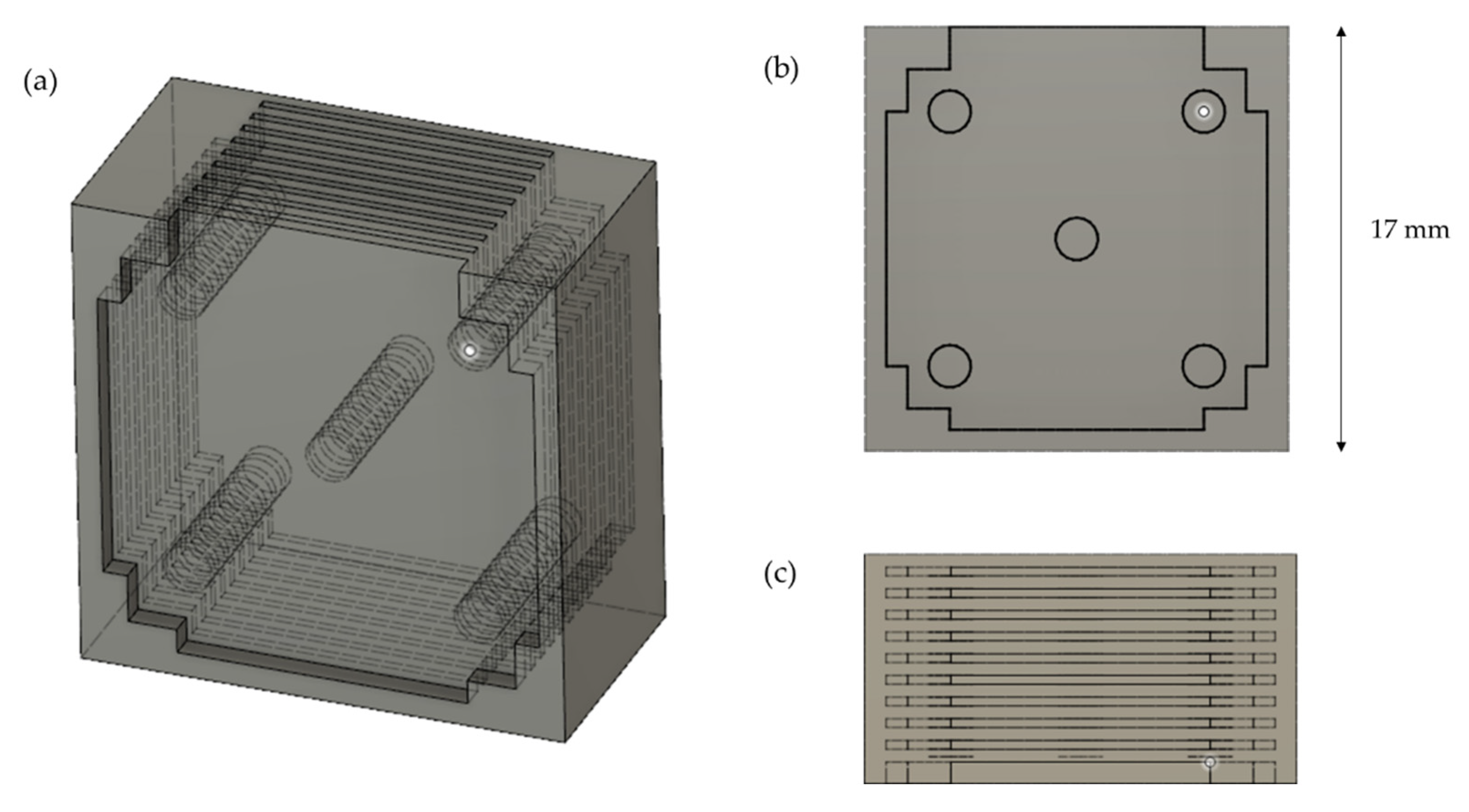
The second attempt to form a mold is indicated in Figure 2a. In this case, the liquid is injected into the interstices between the plates and fills the holes perpendicular to the plates. Once again, a syringe is used to inject the liquid into the mold. The structure perpendicular to the plates holds the object together after gelation and confers it some mechanical strength. Thus, mechanical weakness should no longer be an issue with this design. This design is printed from bottom to top, as indicated in Figure 2. Despite the thinness of the plates, the object prints well. The holes are small enough so that no bridging is needed during the printing process. However, the plates are thin and are easily displaced during the filling process. Additionally, when heated, the plastic becomes even weaker mechanically. As a result, the plates undergo displacements perpendicular to themselves, giving irregular results. Additionally, the holes do not seem to be completely filled with liquid after injection, probably due to the surface tension at play at that moment.
Comparing the stick design and the plate design, it is apparent that either one can be improved to yield satisfactory results. 
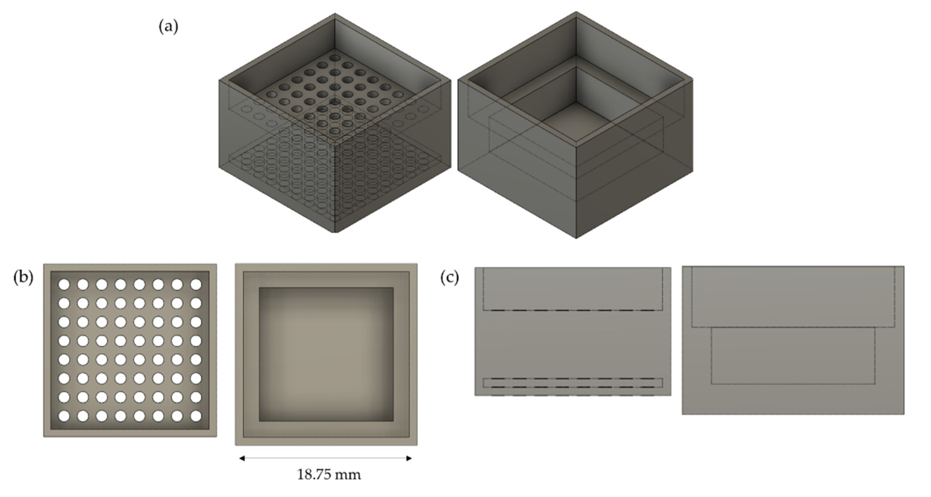
Figure 3a is an attempt at correcting the main flaw of the stick design, which is mechanical weakness of the resulting carbon. That is carried out by (i) limiting the aspect ratio of the sticks by limiting their height to 10 mm and (ii) adding a support underneath the sticks. This is carried out by printing two pieces, and by inserting the piece on the left (mold) of Figure 3a into the piece on the right (support) of Figure 3a. After that, the sol is introduced using a syringe, through one hole of the mold and into the empty part of the support, until it fills the mold up to the edge. This proved successful at creating sounder structures after the curing part, even though the result is not satisfactory yet. The first reason is that the liquid on top of the mold evaporates during the curing process, leading to unwanted modifications in the composition of the material. Moreover, the link between the sticks and the support is weak, so that sticks can easily be broken by weak lateral forces.
In 
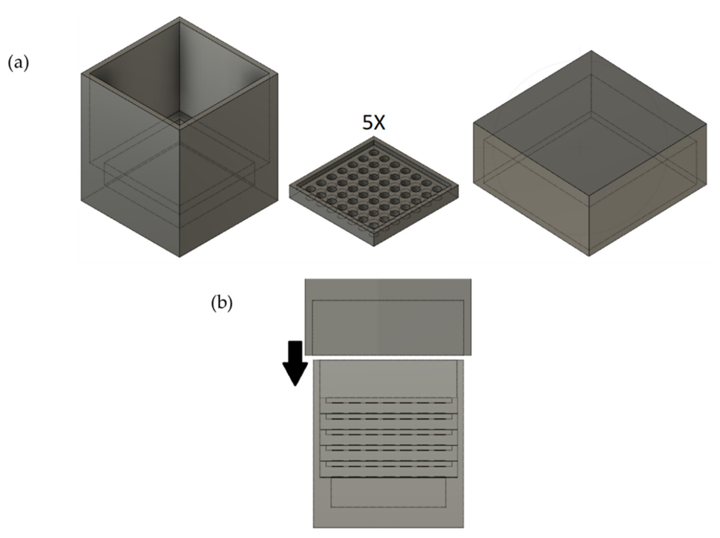
Figure 4a, a cap is added to the design to prevent evaporation of the sol during the curing phase. The sticks are also reinforced by introducing plates at intermediate levels along the height of the design. This modification allows the design to be much more stiff, for the reasonable price of increasing the time of assembly of the different parts. After injection, and after the cap is slid along, the assembly is airtight: it can be turned upside down and shaken without any liquid being spilled. However, during the curing phase, the liquid can penetrate the hollow plastic, as shown by veins appearing in the support. A small amount of liquid can leak out of the assembly that way, even though the assembly stays sealed all along the process. To prevent any loss by evaporation, the molds are placed in an airtight container with a sol of the same composition at the bottom, able to freely evaporate. In the end, this design proved satisfactory. The molds were printed with different hole diameters, as indicated in Table 6.

3.3. Determination of Ideal Parameters of the 3D Printer

As mentioned earlier, default parameters were first used in an attempt to print the selected design, and were varied in a trial-and-error approach. Of course, designing the mold and optimizing these parameters were carried out concurrently, but they are presented in two separate sections for clarity.
Let us first briefly describe and name a few parameters that were varied.
  • Layer height (h): The height of each layer but the first. Thicker layers are printed quicker but result in coarser, less accurate renditions of the design.
  • First layer height (h0): the first layer is sometimes thicker than the other layers to increase adhesion to the bed while printing.
  • Fill density (Fd): Only a fraction of the infill is printed in order to save material and time. The fill density, expressed in %, is the value of this fraction.
  • Presence of a brim: a brim is a detachable part printed next to the object’s first layer to increase its adhesion to the bed.
  • Extrusion multiplier (E): this empirical parameter multiplies the default flow of plastic by a certain value, helping with the quality of the final print.
  • Extruder temperature (TE) and extruder temperature for the first layer (TE0): One of the most important parameters, dependent on the printer, the plastic, the setup, and the environment. A suboptimal extruder temperature can lead to various problems, such as defects in the material and clogging of the extruder.
  • Bed temperature (TB) and bed temperature for the first layer (TB0): Also an important parameter, especially for poorly adhering ABS. It must be carefully chosen to control shrinking and warping phenomena.
  • Nozzle diameter: Using a smaller nozzle leads to slower but more precise prints.
Let us start with the determination of extruder and bed temperatures. The default parameters are the following: TE = TE0 = 255 °C; TB = 110 °C; and TB0 = 100 °C. Alongside the other standard parameters, this leads to warping, i.e., the first layer detaching from the bed after it shrinks. This occurs after printing around 10 layers. Several measures can be taken against this. First, TE can be reduced so that the temperature difference between the material and its surroundings is decreased. After several trials, it was determined that TE = TE0 = 245 °C was the lowest value that could be chosen without increasing ABS’s viscosity too much (which causes excessive use of force or even clogging in the extruder). However, this 10 °C decrease in TE is insufficient. An additional solution was found by decreasing TB0: as the first layer shrinks quicker, it is not as probable that it detaches after the layers above it shrink as well.
However, TB0 cannot be too low; otherwise, the adhesion between the first layer and the bed decreases at the initial stage of printing, so that the extruder head drags the piece it is printing, while it is printing it. A good compromise was found by selecting TB0 = 90 °C. TB must be kept higher (110 °C). The combination of these temperature changes is now sufficient to prevent warping, despite the printed piece not being perfect: the first layers shrink more than the rest of the piece. Luckily, it is of no consequence for the mold if the bottom of the printed material is thick enough, which is the case here. Alongside temperature, the extrusion factor E was varied to decrease warping. The values 0.95, 0.98, 1, 1.02, and 1.05 were tested with various combinations of extrusion and bed temperatures. The general empirical result is that decreasing E decreases warping phenomena, but it leads to imperfect results in the final material, with holes appearing near the bottom of the piece even for E = 0:98. Increasing E has no positive effect and leads to over-extrusion, with rough exterior surfaces and irregular patterns. Thus, the default value E = 1 was kept.
As for the layer heights h and h0, there are several possible pre-sets proposed by the software. h ranges from 0.05 mm to 0.3 mm in those pre-sets, while h0 is always 0.2 mm. It was found that modifying h did not have a significant influence on the visual aspect of the printed piece for h ≤ 0.15 mm. Thus, h = 0.15 mm was chosen to maximize printing speed. For values of h higher than this, the smoothness of the piece decreased, which was also visible for the carbon material produced from the corresponding piece. Modifying h0 (from 0.1 mm to 0.3 mm) had no visible influence, either positive or negative, so that h0 = 0.2 mm was kept.
Finally, the fill density Fd was tested at both pre-set values, i.e., 0.15 and 0.2. The lower value produced satisfactory results less reliably, with adhesion and warping problems seemingly more frequent. Increasing the value above 0.2 was attempted, but led to nothing except increasing the printing time and using more material for similar results.

3.4. Method of Removal of the Mold

This paragraph references the attempts at removing the mold, i.e., at separating the carbon from the plastic, as described in Section 2.5.
(i)
Pyrolyzing the mold leads to a high quantity of exhaust gas so that the pyrolysis oven must be carefully cleaned after the operation.
While this is obviously a surmountable problem, the quality of the final carbon monolith also suffers from this operation: several monoliths were completely shattered after pyrolysis. Finally, previous literature about carbon xerogel properties might not apply if the pyrolysis step is carried out while the material is in contact with plastic, instead of being exposed to inert gas. For these reasons, removing the plastic before the pyrolysis step is necessary.
(ii)
When the mold is dissolved by immersing it repeatedly in the solvent, stirring plays a key role. Indeed, the weaker the agitation, the less efficient the dissolution of the plastic. However, another phenomenon must be taken into account: dissolved ABS strongly settles at the bottom, forming a thick, sticky paste. When using no agitation, disposing of the ABS–acetone mix is particularly hard, as the half-dissolved mold sticks to the bottom of the container, surrounded by sticky paste. Stronger agitations partially solve this problem, but sometimes cause the carbon–mold assembly to break or to move. Thus, a good compromise is to use mild agitation (around 20 RPM). This was found satisfactory to keep the assembly from sticking to the bottom of the container, while not destroying or altering it. An even better solution is to use a metallic net: this way, the sample is held above the bottom of the container. This means that the sample is in contact with clearer solvent (as the dissolved plastic settles to the bottom). Furthermore, the assembly can be easily and safely pulled from the solution by using the net. After the ensuing pyrolysis step, the material did not exhibit major defects, although a few small holes were visible on the surface.
(iii)
Now that the agitation conditions are selected, one can wonder what quantity of solvent is needed to fully remove the mold in these conditions. After experimenting, no definitive quantity could be determined. Indeed, even after 10 cycles of dissolving the plastic, it was still found in small quantities on the carbon material when carefully examined. Perfect removal of the plastic is thus probably too optimistic.
Intermediate attempts were made where the dissolution cycles were continued until the liquid was not opaque any more after 24 h in contact with the mold. This normally happened after three cycles, but a fourth cycle could be added with sonication.
The visual analysis of the carbon material after the pyrolysis step is the same as in the previous case. The leftover plastic after three to four dissolution cycles does not apparently influence this step. Thus, it is more economical to choose this way of doing over the previous one, with several liters of acetone saved for each sample. 
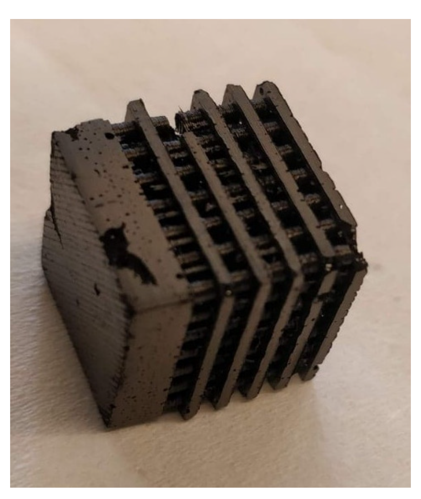
Figure 5 represents the carbon xerogel obtained with the optimized parameters of both 3D printing and mold removal by solvent dissolution.

4. Conclusions

In this work, 3D printing is used to tailor carbon xerogel to specific shapes. Indeed, plastic molds are printed, in which precursor solutions of carbon xerogel are gelled. This work aimed to find the best plastic materials for the mold and optimize the shape and printing of the mold.
To reach these goals, different steps were carried out: (i) selection of the best plastic following multiple criteria such as temperature resistance, compatibility with the carbon xerogel synthesis, the possibility to dissolve the plastic with liquid, cost, and mechanical resistance; then, (ii) different configurations were printed and used to mold carbon xerogels to see if good-quality xerogels could be obtained; finally, (iii) the best method to remove to mold was determined.
Finally, ABS was selected as the best plastic material. The best mold configuration allows the production of up to 64 carbon cylinders in one mold. The 3D-printing parameters were optimized to produce the mold with good quality in a reasonable time. The use of acetone allows the removal of the mold keeping the properties of carbon xerogels.

Author Contributions

Conceptualization, methodology, investigation, analysis and writing, C.W., S.D.L., A.F.L. and J.G.M.; writing—original draft preparation, C.W. and J.G.M.; supervision, funding acquisition and project administration, S.D.L. and J.G.M. All the authors corrected the paper before submission and during the revision process. All authors have read and agreed to the published version of the manuscript.

Funding

This research received no external funding.

Data Availability Statement

The raw/processed data required to reproduce these findings cannot be shared at this time as the data also form part of an ongoing study.

Acknowledgments

J.G.M. and S.D.L. thank the F.R.S.-FNRS for their Postdoctoral Researcher position and Research Director position, respectively.

Conflicts of Interest

The authors declare no conflict of interest.

References

  1. Páez, C.A.; Contreras, M.S.; Léonard, A.; Blacher, S.; Olivera-Fuentes, C.G.; Pirard, J.P.; Job, N. Effect of CO2 Activation of Carbon Xerogels on the Adsorption of Methylene Blue. Adsorption 2012, 18, 199–211. [Google Scholar] [CrossRef]
  2. Karaca, S.; Gürses, A.; Açikyildiz, M.; Ejder (Korucu), M. Adsorption of Cationic Dye from Aqueous Solutions by Activated Carbon. Microporous Mesoporous Mater. 2008, 115, 376–382. [Google Scholar] [CrossRef]
  3. Yu, J.X.; Li, B.H.; Sun, X.M.; Yuan, J.; Chi, R.-A. Polymer Modified Biomass of Baker’s Yeast for Enhancement Adsorption of Methylene Blue, Rhodamine B and Basic Magenta. J. Hazard. Mater. 2009, 168, 1147–1154. [Google Scholar] [CrossRef] [PubMed]
  4. Ip, A.W.M.; Barford, J.P.; McKay, G. A Comparative Study on the Kinetics and Mechanisms of Removal of Reactive Black 5 by Adsorption onto Activated Carbons and Bone Char. Chem. Eng. J. 2010, 157, 434–442. [Google Scholar] [CrossRef]
  5. Job, N.; Pirard, R.; Marien, J.; Pirard, J.P. Porous Carbon Xerogels with Texture Tailored by PH Control during Sol-Gel Process. Carbon 2004, 42, 619–628. [Google Scholar] [CrossRef]
  6. Job, N.; Théry, A.; Pirard, R.; Marien, J.; Kocon, L.; Rouzaud, J.N.; Béguin, F.; Pirard, J.P. Carbon Aerogels, Cryogels and Xerogels: Influence of the Drying Method on the Textural Properties of Porous Carbon Materials. Carbon 2005, 43, 2481–2494. [Google Scholar] [CrossRef]
  7. Job, N.; Maillard, F.; Chatenet, M.; Gommes, C.J.; Lambert, S.; Hermans, S.; Regalbuto, J.R.; Pirard, J.-P. Synthesis and Characterization of Highly Loaded Pt/Carbon Xerogel Catalysts Prepared by the Strong Electrostatic Adsorption Method. Stud. Surf. Sci. Catal. 2010, 175, 169–176. [Google Scholar]
  8. Redwood, B.; Schöffer, F.; Garret, B. The 3D Printing Handbook: Technologies, Design and Applications; 3D Hubs B.V.: Amsterdam, The Netherlands, 2017. [Google Scholar]
  9. Li, H.; Zhang, Y.; Tai, Y.; Zhu, X.; Qi, X.; Zhou, L.; Li, Z.; Lan, H. Flexible Transparent Electromagnetic Interference Shielding Films with Silver Mesh Fabricated Using Electric-Field-Driven Microscale 3D Printing. Opt. Laser Technol. 2022, 148, 107717. [Google Scholar] [CrossRef]
  10. Li, H.; Li, Z.; Li, N.; Zhu, X.; Zhang, Y.F.; Sun, L.; Wang, R.; Zhang, J.; Yang, Z.; Yi, H.; et al. 3D Printed High Performance Silver Mesh for Transparent Glass Heaters through Liquid Sacrificial Substrate Electric-Field-Driven Jet. Small 2022, 18, 2107811. [Google Scholar] [CrossRef]
  11. Khan, S.B.; Irfan, S.; Lam, S.S.; Sun, X.; Chen, S. 3D Printed Nanofiltration Membrane Technology for Waste Water Distillation. J. Water Process Eng. 2022, 49, 102958. [Google Scholar] [CrossRef]
  12. Li, Z.; Li, H.; Zhu, X.; Peng, Z.; Zhang, G.; Yang, J.; Wang, F.; Zhang, Y.F.; Sun, L.; Wang, R.; et al. Directly Printed Embedded Metal Mesh for Flexible Transparent Electrode via Liquid Substrate Electric-Field-Driven Jet. Adv. Sci. 2022, 9, 2105331. [Google Scholar] [CrossRef] [PubMed]
  13. Piedboeuf, M.L.C.; Léonard, A.F.; Traina, K.; Job, N. Influence of the Textural Parameters of Resorcinol-Formaldehyde Dry Polymers and Carbon Xerogels on Particle Sizes upon Mechanical Milling. Colloids Surf. A Physicochem. Eng. Asp. 2015, 471, 124–132. [Google Scholar] [CrossRef]
  14. Piedboeuf, M.L.C.; Léonard, A.F.; Reichenauer, G.; Balzer, C.; Job, N. How Do the Micropores of Carbon Xerogels Influence Their Electrochemical Behavior as Anodes for Lithium-Ion Batteries? Microporous Mesoporous Mater. 2019, 275, 278–287. [Google Scholar] [CrossRef]
  15. Piedboeuf, M.L.C.; Job, N.; Aqil, A.; Busby, Y.; Fierro, V.; Celzard, A.; Detrembleur, C.; Léonard, A.F. Understanding the Influence of Surface Oxygen Groups on the Electrochemical Behavior of Porous Carbons as Anodes for Lithium-Ion Batteries. ACS Appl. Mater. Interfaces 2020, 12, 36054–36065. [Google Scholar] [CrossRef] [PubMed]
  16. Brostow, W.; Chiu, R.; Kalogeras, I.M.; Vassilikou-Dova, A. Prediction of Glass Transition Temperatures: Binary Blends and Copolymers. Mater. Lett. 2008, 62, 3152–3155. [Google Scholar] [CrossRef]
  17. Available online: https://www.simplify3d.com/support/materials-guide/nylon/ (accessed on 4 August 2022).
  18. Kamthai, S.; Magaraphan, R. Thermal and Mechanical Properties of Polylactic Acid (PLA) and Bagasse Carboxymethyl Cellulose (CMCB) Composite by Adding Isosorbide Diesters. AIP Conf. Proc. 2015, 1664, 060006. [Google Scholar]
  19. Available online: http://www.plasticmoulding.ca/polymers/polypropylene.htm (accessed on 4 August 2022).
  20. Available online: https://www.marlinwire.com/blog/7-need-to-know-polypropylene-material-properties (accessed on 4 August 2022).
  21. Romanova, N.; Shafigullin, L.; Gabdrakhmanov, A.; Buyatova, S. Thermal Properties of Products Based on ABS/PC. MATEC Web Conf. 2019, 298, 00016. [Google Scholar] [CrossRef]
  22. Mao, Z.; Zhang, J. Toughening Effect of CPE on ASA/SAN Binary Blends at Different Temperatures. J. Appl. Polym. Sci. 2016, 133, 20. [Google Scholar] [CrossRef]
  23. Dupaix, R.B.; Boyce, M.C. Finite Strain Behavior of Poly(Ethylene Terephthalate) (PET) and Poly(Ethylene Terephthalate)-Glycol (PETG). Polymer 2005, 46, 4827–4838. [Google Scholar] [CrossRef]
  24. Solarski, S.; Ferreira, M.; Devaux, E. Characterization of the Thermal Properties of PLA Fibers by Modulated Differential Scanning Calorimetry. Polymer 2005, 46, 11187–11192. [Google Scholar] [CrossRef]
  25. Hummel, S.R.; Hossain, K.; Hayes, G.T. Biaxial Stress Relaxation of High Impact Polystyrene (HIPS) Above the Glass Transition Temperature. Polym. Eng. Sci. 2001, 41, 566–574. [Google Scholar] [CrossRef]
  26. Yang, H.; Lai, M.; Liu, W.; Sun, C.; Liu, J. Morphology and Thermal and Mechanical Properties of PBT/HIPS and PBT/HIPS-G-GMA Blends. J. Appl. Polym. Sci. 2002, 85, 2600–2608. [Google Scholar] [CrossRef]
  27. Alcock, B.; Cabrera, N.O.; Barkoula, N.M.; Reynolds, C.T.; Govaert, L.E.; Peijs, T. The Effect of Temperature and Strain Rate on the Mechanical Properties of Highly Oriented Polypropylene Tapes and All-Polypropylene Composites. Compos. Sci. Technol. 2007, 67, 2061–2070. [Google Scholar] [CrossRef]
  28. Kelco Chemical Compatibility Chart Abs. Available online: https://www.kelco.com.au/wp-content/uploads/2009/02/abs-chemical-compatibility-guide.pdf (accessed on 5 August 2022).
  29. Heikkinen, I.T.S.; Kauppinen, C.; Liu, Z.; Asikainen, S.M.; Spoljaric, S.; Seppälä, J.V.; Savin, H.; Pearce, J.M. Chemical Compatibility of Fused Filament Fabrication-Based 3-D Printed Components with Solutions Commonly Used in Semiconductor Wet Processing. Addit. Manuf. 2018, 23, 99–107. [Google Scholar] [CrossRef] [Green Version]
  30. Available online: https://www.simplify3d.com/support/materials-guide/hips/ (accessed on 4 August 2022).
  31. Available online: https://www.osti.gov/servlets/purl/4970 (accessed on 4 August 2022).
  32. Chen, Y.; Li, J.; Lu, J.; Ding, M.; Chen, Y. Synthesis and Properties of Poly(Vinyl Alcohol) Hydrogels with High Strength and Toughness. Polym. Test. 2022, 108, 107516. [Google Scholar] [CrossRef]
  33. Available online: https://www.calpaclab.com/polypropylene-chemical-compatibility-chart/ (accessed on 4 August 2022).
  34. Available online: https://rigid.ink/blogs/news/acetone-vapor-smoothing (accessed on 4 August 2022).
  35. Boborodea, A.; O’Donohue, S. Characterization of Polypropylene in Dibutoxymethane by High-Temperature Gel Permeation Chromatography with Triple Detection. Int. J. Polym. Anal. Charact. 2015, 20, 724–732. [Google Scholar] [CrossRef]
  36. Cheruthazhekatt, S.; Robertson, D.D.; Brand, M.; van Reenen, A.; Pasch, H. Solution Crystallization and Dissolution of Polyolefins as Monitored by a Unique Analytical Tool: Solution Crystallization Analysis by Laser Light Scattering. Anal. Chem. 2013, 85, 7019–7023. [Google Scholar] [CrossRef]
  37. Available online: https://www.simplify3d.com/support/materials-guide/abs/ (accessed on 4 August 2022).
  38. Available online: http://xahax.com/subory/Spec_ABS.pdf (accessed on 4 August 2022).
  39. Available online: https://dielectricmfg.com/knowledge-base/abs/ (accessed on 4 August 2022).
  40. Available online: https://www.simplify3d.com/support/materials-guide/asa/ (accessed on 4 August 2022).
  41. Available online: https://omnexus.specialchem.com/polymer-properties/properties/coefficient-of-linear-thermal-expansion (accessed on 4 August 2022).
  42. Available online: https://designerdata.nl/materials/plastics/thermo-plastics/acrylonitrile---styrene---acrylester (accessed on 4 August 2022).
  43. Available online: https://dielectricmfg.com/knowledge-base/petg/ (accessed on 4 August 2022).
  44. Available online: https://polymerdatabase.com/Commercial%20Polymers/PS2.html (accessed on 4 August 2022).
  45. Available online: https://www.simplify3d.com/support/materials-guide/polypropylene/ (accessed on 4 August 2022).
  46. Available online: https://www.engineeringtoolbox.com/linear-expansion-coefficients-d_95.html (accessed on 4 August 2022).
  47. Available online: https://designerdata.nl/materials/plastics/thermo-plastics/polypropylene-(cop.) (accessed on 4 August 2022).
Figure 1. Stick design. (a) Stick design: 3D view. The object is 20 mm × 20 mm × 10 mm. The holes’ diameter is 2 mm. The plates are 0.25mm-thick and are separated by 0.25 mm. (b) Stick design 1: top view. Inside circumradius: 400 μm, outside circumradius: 500 μm. Distance between two adjacent hexagons: 80 μm. (c) Stick design 2: top view. Side: 500 μm, distance between two adjacent squares: 500 μm. (d) Stick design 3: top view. Diameter: 750 μm, distance between two adjacent circles: 500 μm.
Processes 10 01979 g001
Figure 2. Plate design. (a) Plate design: 3D view. The overall dimensions of the object are 17 mm × 17 mm × 14 mm. (b) Plate design: front view. The xy-positions of the holes (ϕ = 4 mm) are indicated. (c) Plate design: top view. The holes go through all the plates so that the carbon object will be a single body. The empty space between two consecutive plates is 0.4 mm.
Processes 10 01979 g002
Figure 3. Supported stick design. (a) Supported stick design: 3D view. The object on the left (mold) is inserted into the object on the right (support). The space (tolerance) between both parts is 0.25 mm. (b) Supported stick design: top view. The holes have a diameter ϕ = 1.5 mm. The bottom part of the support is a square of side 18.75 mm. (c) Supported stick design: side view. The bottom part of the support has a depth of 6.5 mm; the holes in the mold are 10mm-deep, and the vertical gap between the holes and the edge of the mold is 5mm-high.
Processes 10 01979 g003
Figure 4. Supported plate–stick mixed design. (a) Supported plate–stick mixed design. The objects in the middle (molds) are inserted into the object on the left (support) and covered by the object on the right (cap) after injection of sol. The space (tolerance) between a mold and the support is 0.25 mm; the tolerance between the cap and the support is also 0.25 mm. (b) Side view of the overall assembly, with the cap ready to slide along the support–mold assembly. The stick-shaped parts between two adjacent plates are 2mm-long while the plates are 1mm-thick. The empty spaces below and above the plate–stick combination are both 5mm-deep. Other dimensions are identical to the supported stick design.
Processes 10 01979 g004
Figure 5. Best carbon xerogel obtained with the optimized parameters of both 3D printing and mold removal by solvent dissolution.
Processes 10 01979 g005
Table 1. Glass transition temperatures of pre-selected polymers.
PolymerTg (°C)Source
ABS105[21]
ASA113[22]
PETG80[23]
PLA<67[24]
HIPS97[25,26]
PVA80[16]
PP- a[27]
a: irrelevant.
Table 2. Chemical resistance of pre-selected polymers according to literature.
PolymerResistance to WaterResistance to FormaldehydeSource
ABSExcellentExcellent[28]
ASAExcellentUnknown[29]
PETGExcellentExcellent[23]
HIPSExcellentUnknown[30]
PVASoluble- a[31,32]
PPExcellentExcellent[33]
a: irrelevant.
Table 3. Cost, printability, and relevant mechanical properties of polymers.
PolymerCost (EUR /kg)PrintabilityFrequent ProblemsCoefficient of Thermal Expansion (K−1)Young Modulus (MPa)
ABS26.74Medium–goodHeavy warping, dimensional inaccuracies [37]1.01 × 10⁻⁴ [38]~2000 [39]
ASA41.89MediumHeavy warping, dangerous fumes [40]~8.5 × 10⁻⁵ [41]2200 [42]
PETG44.33Very goodOozing8 × 10−5 [41]~ 2050 [43]
HIPS32.60Medium–goodWarping, poor bed adhesion [30]~9 × 10⁻⁵ [44]~2000 [44]
PP46.64PoorHeavy warping, poor adhesion, hygroscopic [45]~8 × 10⁻⁵ [46]1325 [47]
Table 4. Cost and health/environmental impact of selected solvents. The target plastics can be dissolved by the solvent on the same line, as checked in the laboratory.
SolventCost (EUR /L)EcotoxicityHealth ImpactTarget Plastic(s)
Acetone25.9LowLowABS, ASA
Ethyl acetate24.85LowLowABS
Dichloromethane18.3MediumHazardousABS, ASA
Trichloromethane51.6MediumHazardousASA
Nitrobenzene127.5HazardousHazardousASA
d-limonene176.8LowMediumHIPS
Table 5. Summary of advantages and disadvantages of possible plastics for 3D printing selection. Subjectively judged using the following scale: ++/+/−/X, where ++ is ideal, + is good, − is a minor drawback, and X is grounds for rejection. Empty cells correspond to plastics that were rejected before judging the corresponding criterion.
PlasticTemperature ResistanceChemical ResistanceAbility to DissolvedMechanical Properties aCost bHazardousness b
ABS+++++++++
ASA++++++++
PETG++X
PLAX
HIPS++++++++
PVAX
PP+++
a: including printability, b: including both the plastic and its solvent.
Table 6. Characteristics of the different samples produced from the supported plate–stick mixed design (Figure 4a).
SampleNumber of SticksDiameter of Stick (mm)Lateral Space between Adjacent Sticks (mm)
25 s2531
36 s362.331
49 s491.861
64 s641.51
Publisher’s Note: MDPI stays neutral with regard to jurisdictional claims in published maps and institutional affiliations.

