
Improving Mechanical Oscillator Cooling in a Double-Coupled Cavity Optomechanical System with an Optical Parametric Amplifier

Abstract
:1. Introduction
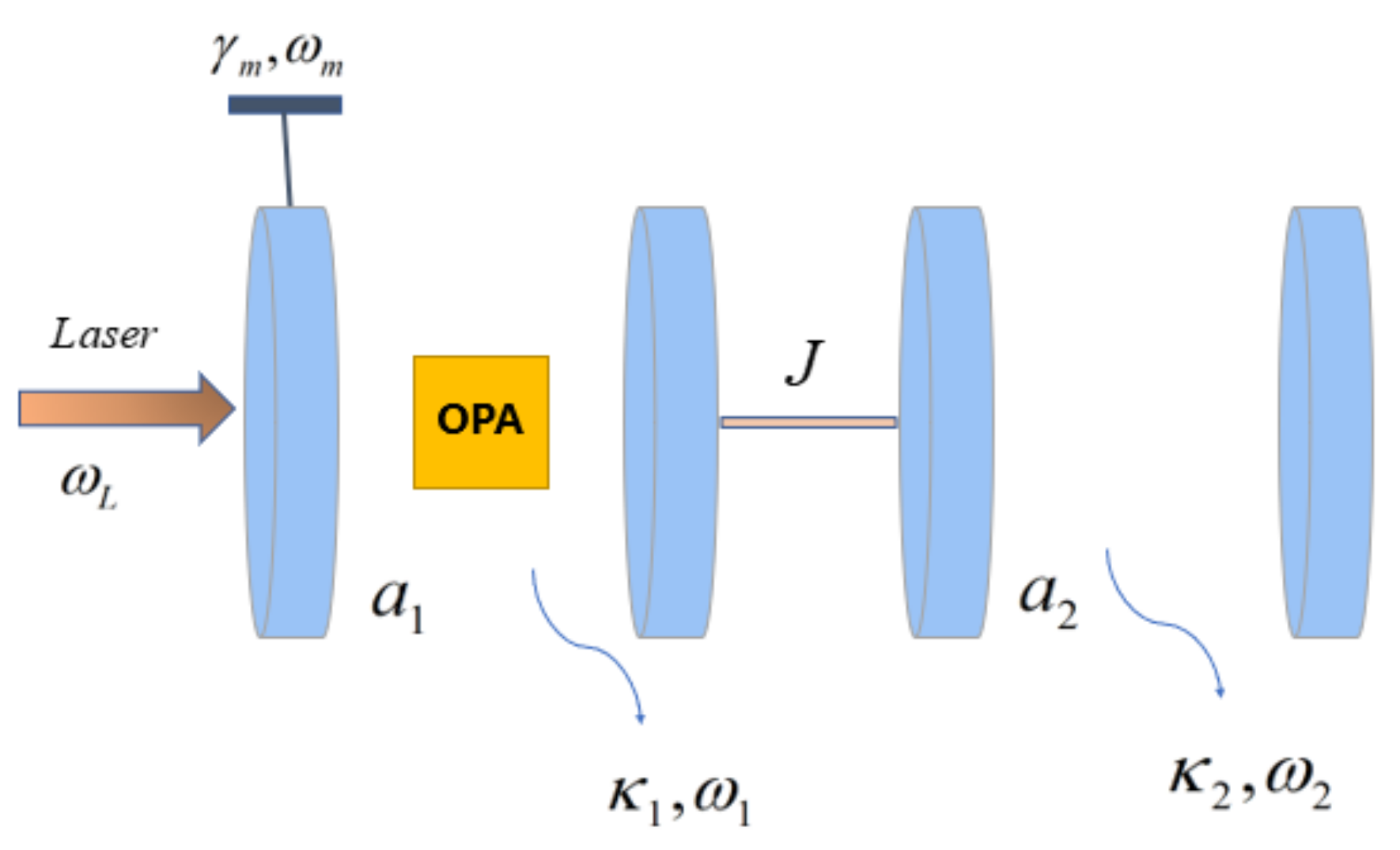
2. Model
3. Radiation Pressure and Quantum Fluctuations
4. Results and Discussions
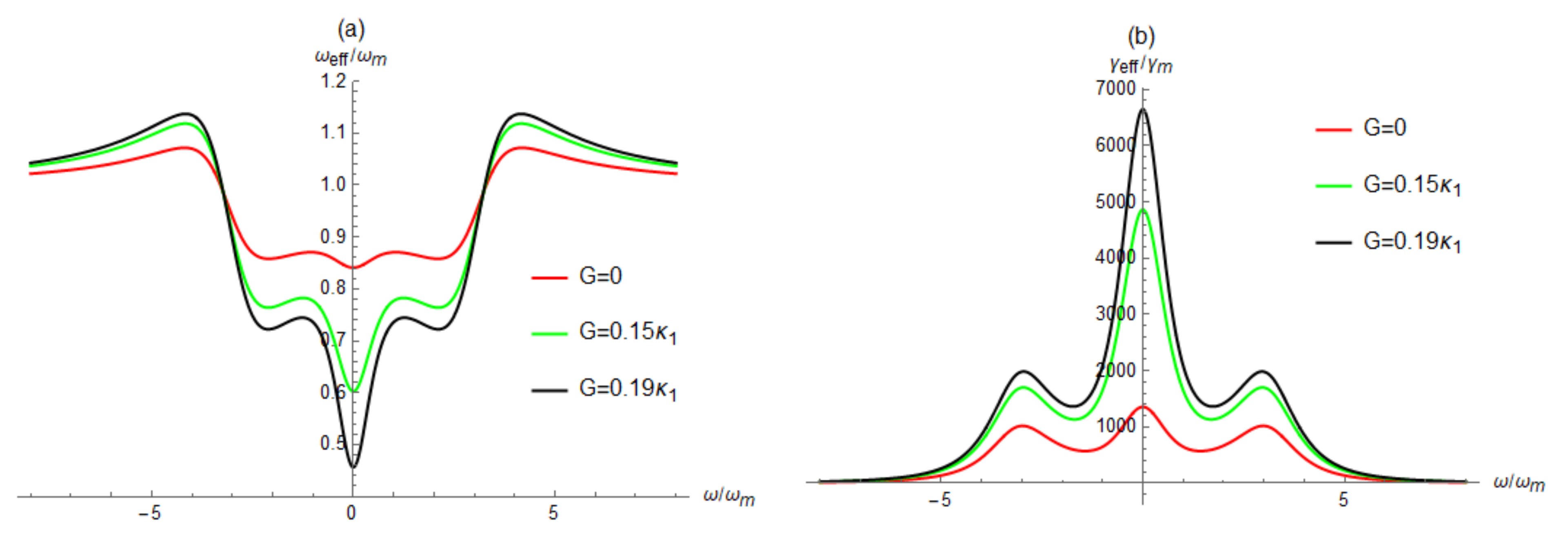
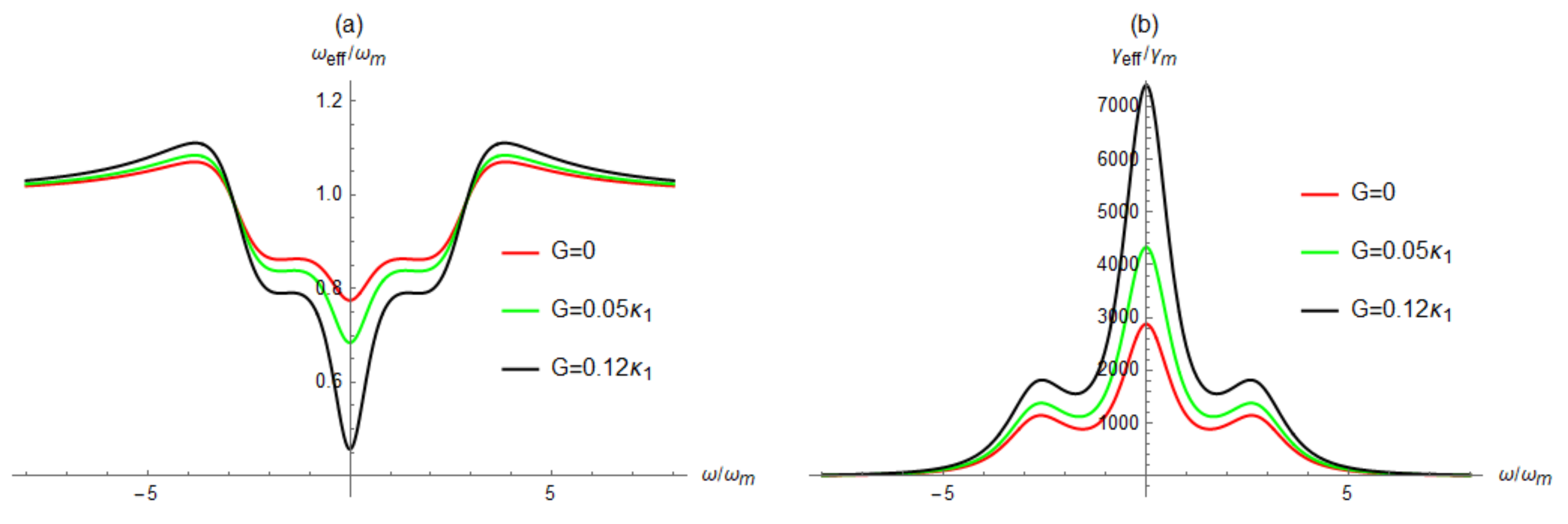
4.1. Effective Resonance Frequency and Effective Damping Rate of Mechanical Oscillator
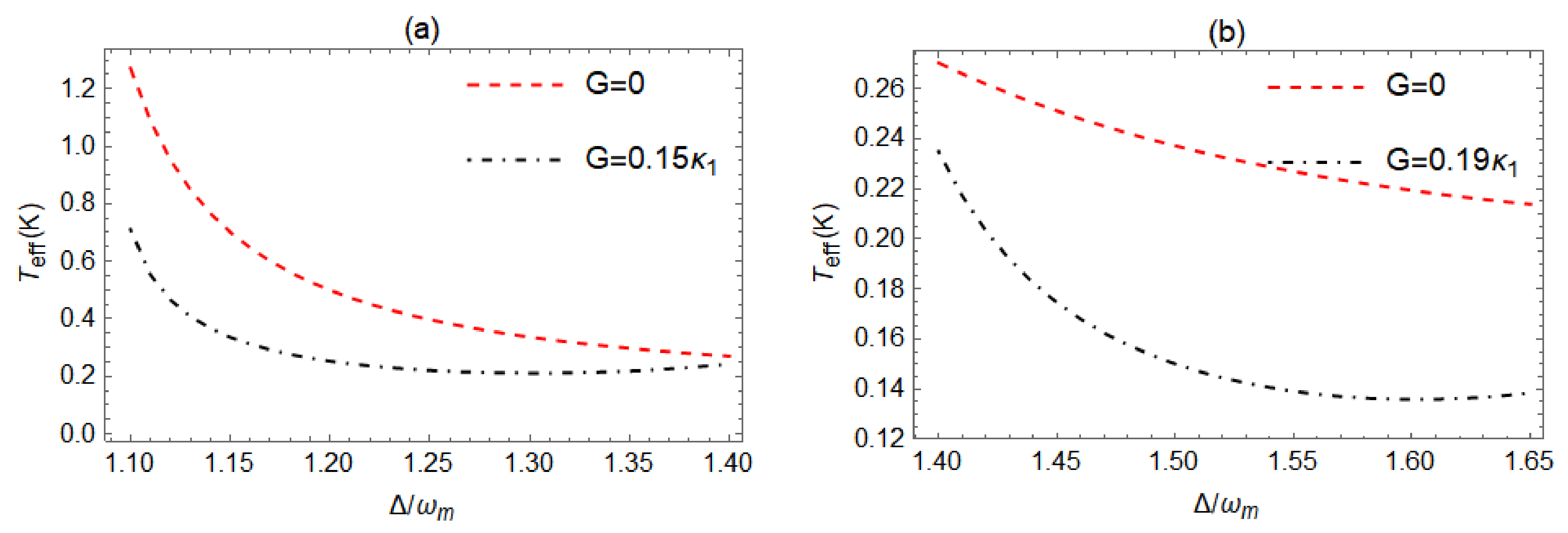
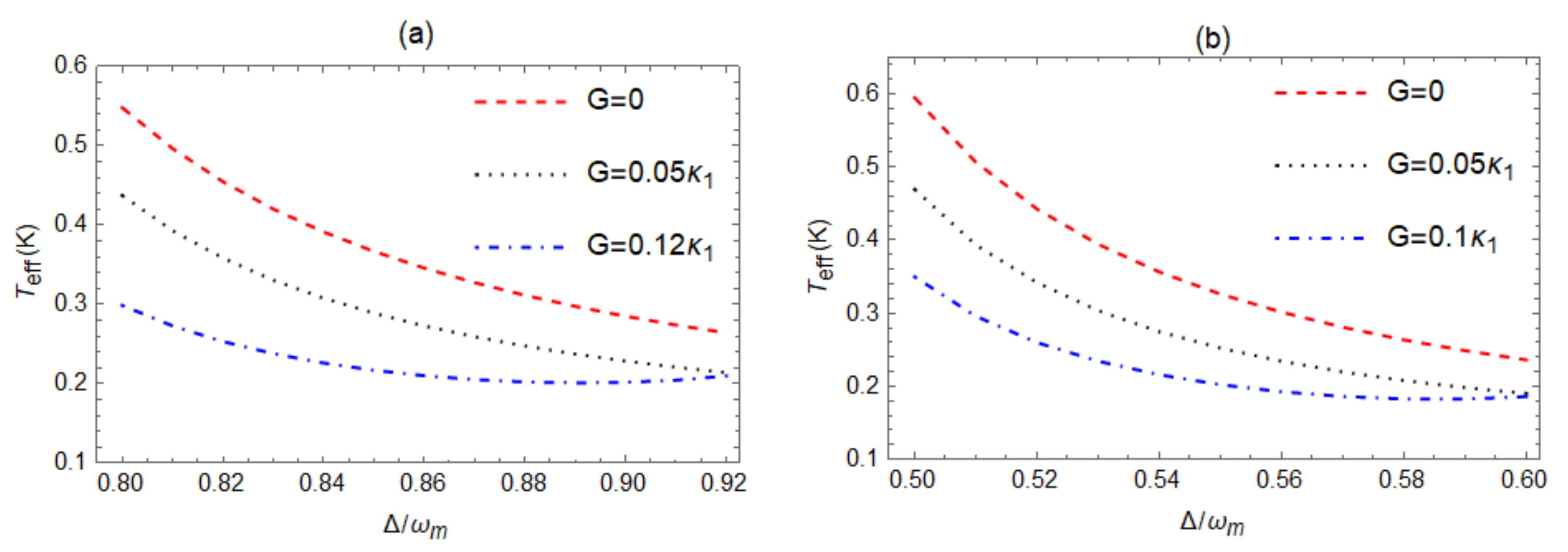
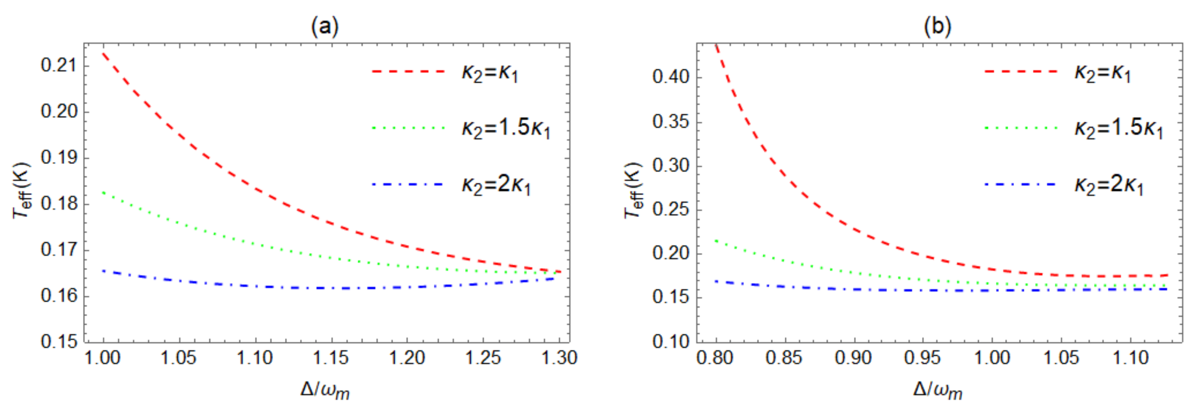
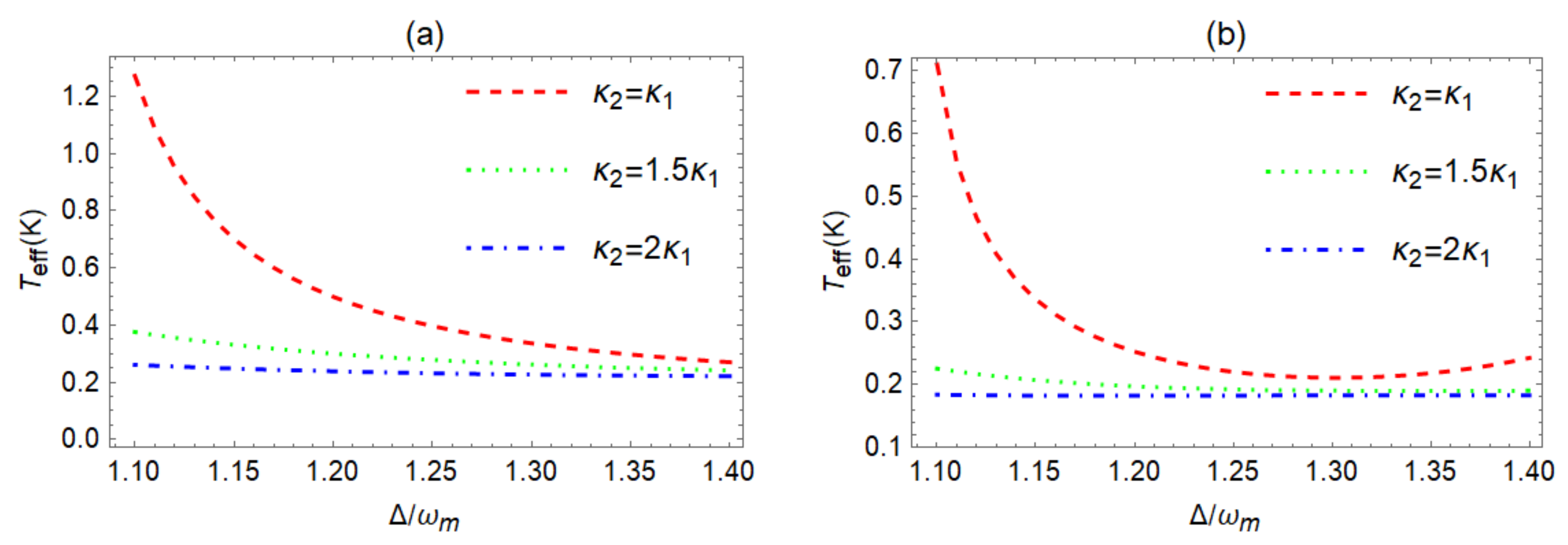
4.2. Cooling the Mechanical Oscillator
5. Conclusions
Author Contributions
Funding
Data Availability Statement
Conflicts of Interest
References
- Aspelmeyer, M.; Kippenberg, T.J.; Marquardt, F. Cavity optomechanics. Rev. Mod. Phys. 2014, 86, 1391–1452. [Google Scholar] [CrossRef]
- Kippenberg, T.J.; Vahala, K.J. Cavity optomechanics: Back-action at the mesoscale. Science 2008, 321, 1172–1176. [Google Scholar] [CrossRef] [PubMed]
- Sawadsky, A.; Kaufer, H.; Nia, R.M.; Tarabrin, S.P.; Khalili, F.Y.; Hammerer, K.; Schnabel, R. Observation of generalized optomechanical coupling and cooling on cavity resonance. Phys. Rev. Lett. 2015, 114, 043601. [Google Scholar] [CrossRef] [PubMed]
- Cleland, A.N.; Geller, M.R. Superconducting qubit storage and entanglement with nanomechanical resonators. Phys. Rev. Lett. 2004, 93, 070501. [Google Scholar] [CrossRef] [PubMed]
- Kotler, S.; Peterson, A.G.; Shojaee, E.; Lecocq, F.; Cicak, K.; Kwiatkowski, A.; Geller, S.; Glancy, S.; Knill, E.; Simmonds, W.R.; et al. Direct observation of deterministic macroscopic entanglement. Science 2021, 372, 622. [Google Scholar] [CrossRef]
- Tetard, L.; Passian, A.; Venmar, K.T.; Lynch, R.M.; Voy, B.H.; Shekhawat, G.; Dravid, V.P.; Thundat, T. Imaging nanoparticles in cells by nanomechanical holography. Nat. Nanotechnol. 2008, 3, 501–505. [Google Scholar] [CrossRef]
- Clerk, A.A.; Marquardt, F.; Jacobs, K. Back-action evasion and squeezing of a mechanical resonator using a cavity detector. New J. Phys. 2008, 10, 095010. [Google Scholar] [CrossRef]
- Wollman, E.E.; Lei, C.U.; Weinstein, A.J.; Suh, J.; Kronwald, A.; Marquardt, F.; Clerk, A.A.; Schwab, K.C. Quantum squeezing of motion in a mechanical resonator. Science 2015, 349, 952–955. [Google Scholar] [CrossRef]
- LaHaye, M.D.; Buu, O.; Camarota, B.; Schwab, K.C. Approaching the quantum limit of a nanomechanical resonator. Science 2004, 304, 74–77. [Google Scholar] [CrossRef]
- Zheng, S.B.; Guo, G.C. Efficient scheme for two-atom entanglement and quantum information processing in cavity QED. Phys. Rev. Lett. 2000, 85, 2392–2395. [Google Scholar] [CrossRef]
- Bassi, A.; Ippoliti, E.; Adler, S.L. Towards quantum superpositions of a mirror: An exact open systems analysis. Phys. Rev. Lett. 2005, 94, 030401. [Google Scholar] [CrossRef]
- Zeng, W.; Nie, W.J.; Li, L.; Chen, A.X. Ground-state cooling of a mechanical oscillator in a hybrid optomechanical system including an atomic ensemble. Sci. Rep. 2017, 7, 17258. [Google Scholar] [CrossRef] [PubMed]
- Chen, X.; Liu, Y.C.; Peng, P.; Zhi, Y.Y.; Xiao, Y.F. Cooling of macroscopic mechanical resonators in hybrid atom-optomechanical systems. Phys. Rev. A 2015, 92, 033841. [Google Scholar] [CrossRef]
- Chan, J.; Alegre, T.; Safavi-Naeini, A.H.; Hill, J.T.; Krause, A.; Groblacher, S.; Aspelmeyer, M.; Painter, O. Laser cooling of a nanomechanical oscillator into its quantum ground state. Nature 2011, 478, 89. [Google Scholar] [CrossRef] [PubMed]
- Liu, Y.C.; Hu, Y.W.; Wei, W.C.; Xiao, Y.F. Review of cavity optomechanical cooling. Chin. Phys. B 2014, 22, 114213. [Google Scholar] [CrossRef]
- Gigan, S.; Böhm, H.R.; Paternostro, M.; Blaser, F.; Langer, G.; Hertzberg, J.B.; Schwab, K.C.; Bäuerle, D.; Aspelmeyer, M.; Zeilinger, A. Self-cooling of a micromirror by radiation pressure. Nature 2006, 444, 67–70. [Google Scholar] [CrossRef]
- Dantan, A.; Genes, C.; Vitali, D.; Pinard, M. Self-cooling of a movable mirror to the ground state using radiation pressure. Phys. Rev. A 2008, 77, 011804. [Google Scholar] [CrossRef]
- Groblacher, S.; Gigan, S.; Bohm, H.R.; Zeilinger, A.; Aspelmeyer, M. Radiation-pressure self-cooling of a micromirror in a cryogenic environment. Europhys. Lett. 2008, 81, 54003. [Google Scholar] [CrossRef]
- Barzanjeh, S.; Naderi, M.H.; Soltanolkotabi, M. Back-action ground-state cooling of a micromechanical membrane via intensity-dependent interaction. Phys. Rev. A 2011, 84, 023803. [Google Scholar] [CrossRef]
- Arcizet, O.; Cohadon, P.F.; Briant, T.; Pinard, M.; Heidmann, A. Radiation-pressure cooling and optomechanical instability of a micromirror. Nature 2006, 444, 71–74. [Google Scholar] [CrossRef] [PubMed]
- Schliesser, A.; Del’Haye, P.; Nooshi, N.; Vahala, K.J.; Kippenberg, T.J. Radiation pressure cooling of a micromechanical oscillator using dynamical backaction. Phys. Rev. Lett. 2006, 97, 243905. [Google Scholar] [CrossRef]
- Asjad, M.; Abari, N.E.; Zippilli, S.; Vitali, D. Optomechanical cooling with intracavity squeezed light. Opt. Express 2019, 27, 32427–32444. [Google Scholar] [CrossRef]
- Mancini, S.; Vitali, D.; Tombesi, P. Optomechanical cooling of a macroscopic oscillator by homodyne feedback. Phys. Rev. Lett. 1998, 80, 688. [Google Scholar] [CrossRef]
- Arcizet, O.; Cohadon, P.F.; Briant, T.; Pinard, M.; Heidmann, A.; Mackowski, J.-M.; Michel, C.; Pinard, L.; Français, O.; Rousseau, L. High-sensitivity optical monitoring of a micromechanical resonator with a quantum-limited optomechanical sensor. Phys. Rev. Lett. 2006, 97, 133601. [Google Scholar] [CrossRef]
- Poggio, M.; Degen, C.L.; Mamin, H.J.; Rugar, D. Feedback cooling of a cantilever′s fundamental mode below 5 mK. Phys. Rev. Lett. 2007, 99, 017201. [Google Scholar] [CrossRef] [PubMed]
- Rossi, M.; Mason, D.; Chen, J.; Tsaturyan, Y.; Schliesser, A. Measurement-based quantum control of mechanical motion. Nature 2018, 563, 53. [Google Scholar] [CrossRef] [PubMed]
- Corbitt, T.; Wipf, C.; Bodiya, T.; Ottaway, D.; Sigg, D.; Smith, N.; Whitcomb, S.; Mavalvala, N. Optical dilution and feedback cooling of a gram-scale oscillator to 6.9 mK. Phys. Rev. Lett. 2007, 99, 160801. [Google Scholar] [CrossRef]
- Genes, C.; Vitali, D.; Tombesi, P.; Gigan, S.; Aspelmeyer, M. Ground-state cooling of a micromechanical oscillator: Comparing cold damping and cavity-assisted cooling schemes. Phys. Rev. A 2008, 79, 039903. [Google Scholar] [CrossRef]
- Wilson-Rae, I.; Nooshi, N.; Zwerger, W.; Kippenberg, T.J. Theory of ground state cooling of a mechanical oscillator using dynamical backaction. Phys. Rev. Lett. 2007, 99, 093901. [Google Scholar] [CrossRef] [PubMed]
- Marquardt, F.; Chen, J.P.; Clerk, A.A.; Girvin, S.M. Quantum theory of cavity-assisted sideband cooling of mechanical motion. Phys. Rev. Lett. 2007, 99, 093902. [Google Scholar] [CrossRef] [PubMed]
- Guo, Y.J.; Li, K.; Nie, W.J.; Li, Y. Electromagnetically-induced-transparency-like ground-state cooling in a double-cavity optomechanical system. Phys. Rev. A 2014, 90, 053841. [Google Scholar] [CrossRef]
- Liu, Y.C.; Xiao, Y.F.; Luan, X.S.; Gong, Q.H.; Wong, C.W. Coupled cavities for motional ground-state cooling and strong optomechanical coupling. Phys. Rev. A 2015, 91, 033818. [Google Scholar] [CrossRef]
- Ye, X.Q.; Huang, S.M.; Deng, L.; Chen, A.X. Improving the stochastic feedback cooling of a mechanical oscillator using a degenerate parametric amplifier. Photonics 2022, 9, 264. [Google Scholar] [CrossRef]
- Huang, S.M.; Agarwal, G.S. Enhancement of cavity cooling of a micromechanical mirror using parametric interactions. Phys. Rev. A 2009, 79, 013821. [Google Scholar] [CrossRef]
- Huang, S.M.; Chen, A.X. Improving the cooling of a mechanical oscillator in a dissipative optomechanical system with an optical parametric amplifier. Phys. Rev. A 2018, 98, 063818. [Google Scholar] [CrossRef]
- Lau, H.K.; Clerk, A.A. Ground-state cooling and high-fidelity quantum transduction via parametric driven bad-cavity optomechanics. Phys. Rev. Lett. 2020, 124, 103602. [Google Scholar] [CrossRef] [PubMed]
- Gardiner, C.W.; Zoller, P. Quantum Noise; Springer: Berlin/Heidelberg, Germany, 1991; Available online: https://link.springer.com/book/9783540665717 (accessed on 1 December 2020).
- Giovannetti, V.; Vitali, D. Phase-noise measurement in a cavity with a movable mirror undergoing quantum Brownian motion. Phys. Rev. A 2001, 63, 023812. [Google Scholar] [CrossRef]
- Dejesus, E.X.; Kaufman, C. Routh-Hurwitz criterion in the examination of eigenvalues of a system of nonlinear ordinary differential equations. Phys. Rev. A 1987, 35, 5288. [Google Scholar] [CrossRef]
- Cohadon, P.F.; Heidmann, A.; Pinard, M. Cooling of a mirror by radiation pressure. Phys. Rev. Lett. 1999, 83, 3174. [Google Scholar] [CrossRef]


Disclaimer/Publisher’s Note: The statements, opinions and data contained in all publications are solely those of the individual author(s) and contributor(s) and not of MDPI and/or the editor(s). MDPI and/or the editor(s) disclaim responsibility for any injury to people or property resulting from any ideas, methods, instructions or products referred to in the content. |
© 2023 by the authors. Licensee MDPI, Basel, Switzerland. This article is an open access article distributed under the terms and conditions of the Creative Commons Attribution (CC BY) license (https://creativecommons.org/licenses/by/4.0/).
Share and Cite
Pan, P.; Chen, A.; Deng, L. Improving Mechanical Oscillator Cooling in a Double-Coupled Cavity Optomechanical System with an Optical Parametric Amplifier. Mathematics 2023, 11, 2218. https://doi.org/10.3390/math11092218
Pan P, Chen A, Deng L. Improving Mechanical Oscillator Cooling in a Double-Coupled Cavity Optomechanical System with an Optical Parametric Amplifier. Mathematics. 2023; 11(9):2218. https://doi.org/10.3390/math11092218
Chicago/Turabian StylePan, Peipei, Aixi Chen, and Li Deng. 2023. "Improving Mechanical Oscillator Cooling in a Double-Coupled Cavity Optomechanical System with an Optical Parametric Amplifier" Mathematics 11, no. 9: 2218. https://doi.org/10.3390/math11092218