3.1. Secondary Flow of Two-Phase Flow
Gorse et al. [
15] studied the airflow characteristics in a vented bearing chamber using a 3D Laser Doppler Anemometry (LDA) system, and proposed the criterion for the transition between the rotational speed drive mode (RSDM) and the sealing air driven mode (SADM) by the velocity ratio (
), which is defined as follows:
where
is the rotational speed of the shaft,
is the air inlet velocity;
is the Reynolds number of the rotor, and
is the Reynolds number of air. For
4.2, it is the rotational speed driving mode with twin vortices in the chamber. For
4.2, it is the sealed air drive mode with only a single vortex.
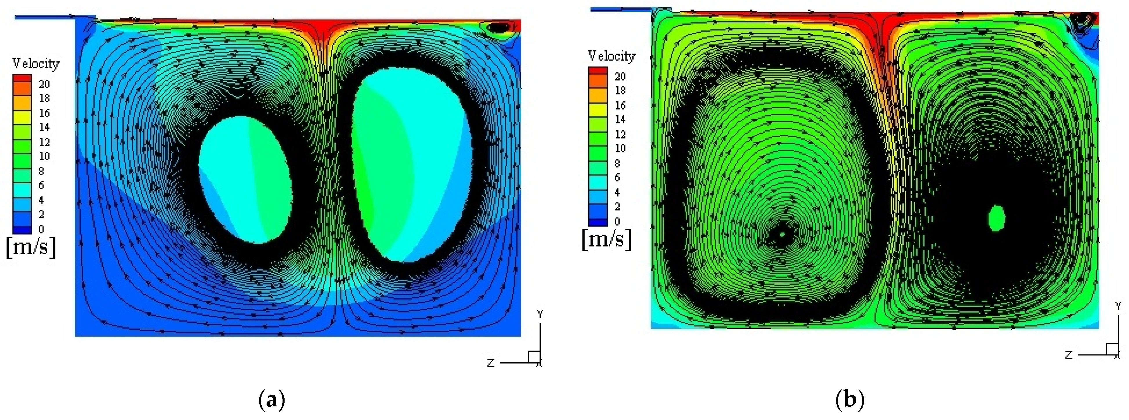
Figure 6 shows the secondary flow field at 10,000 rpm in the 90° cross section. It can be seen that there exists a transition of twin vortices to a single vortex for the unsteady process in the ventless bearing chamber under the aspect ratio of 0.712. At 0.027 s, there are twin hollow vortices with similar sizes and opposite directions, the velocity decreases gradually from the vortex center to the outside except at the inlet, and the velocity near the rotor gradually decreases from the center to both sides and the radial direction. The circulations of twin vortices collide at 1/2b in the axial direction. At this point, the actual vorticity value obtained by selecting a vorticity level of 0.05 is 4670.6 s
−1.
Figure 6b shows that the vortex of the air inlet side begins to disperse, the vortex core becomes larger, the vortex intensity decreases, and the vortex intensity at the oil inlet side increases. The average vorticity value in the bearing chamber is 4889.2 s
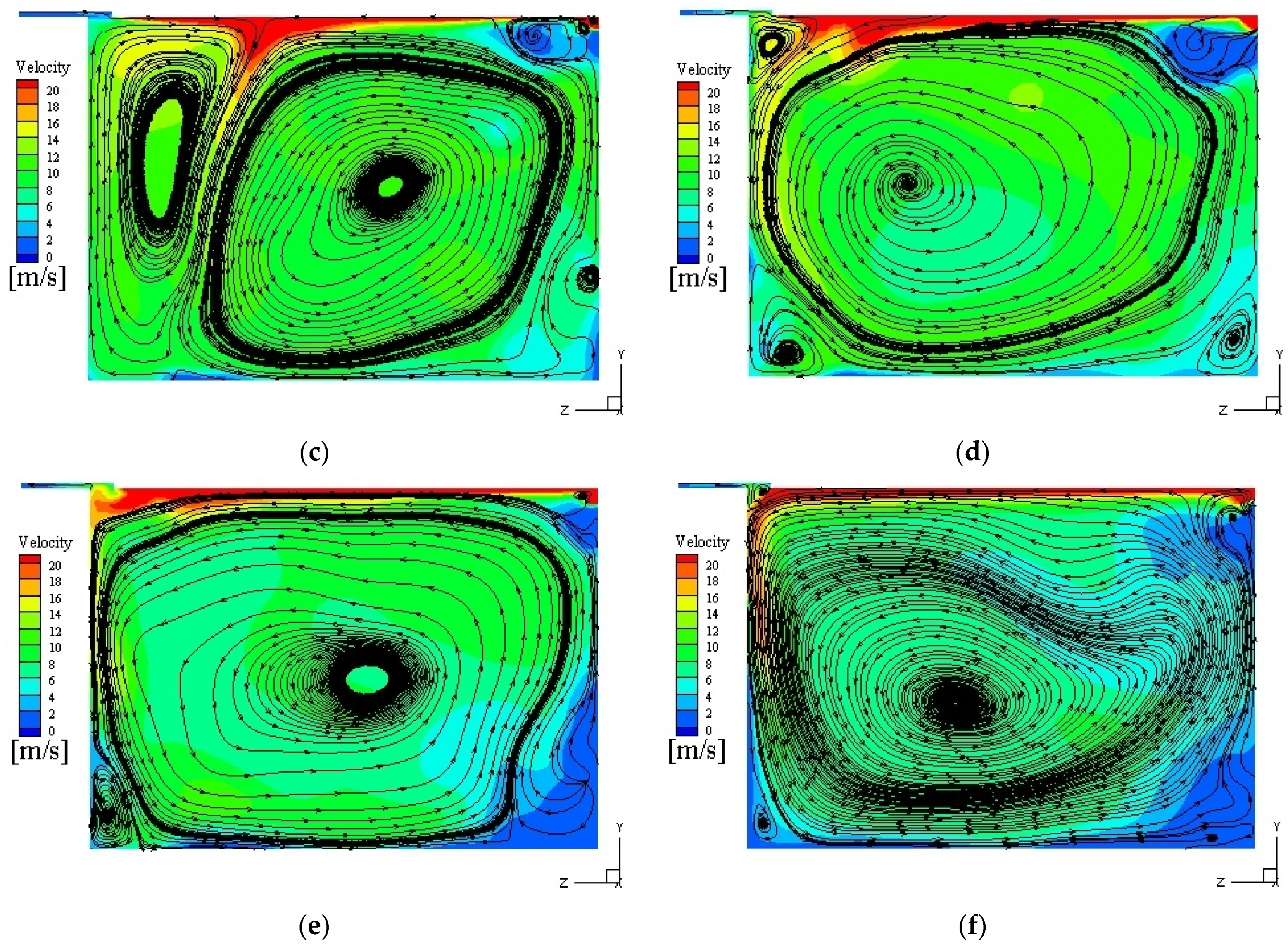
−1. At 0.363 s, the vortex of the oil inlet side gradually merges with the vortex of the air inlet side, and the vortex core shifts to a higher velocity region. The motion of vortices is related to the dominant role of the rotor shear force, which is consistent with the evolution of the rotational speed driving mode into transition mode (TM) in the literature [
15]. Then, the twin vortices merge into a single vortex with the vortex core at the air inlet side, and there are several low-velocity eddies at the corner of the chamber (
Figure 6d). At 0.528 s, the small eddies in the corner are swallowed up by a single vortex. Finally, the vortex core is located in the center of the chamber, and the motion of oil/gas two-phase in the bearing chamber tends to be stable (
Figure 6f). In this state, the tangential velocity direction of the vortex is consistent with the oil inlet direction, which is defined as the lubricating oil drive mode (ODM). The numerical simulation results of Singh et al. [
16] at 10,000 rpm and an air flow rate of 10 g/s also show a similar result.
Gorse et al. [
15] characterized the drive mode using the ratio of rotational speed to air velocity. However, the influence of oil flow on the drive mode cannot be ignored due to the simultaneous existence of oil/gas two-phase in the chamber. Therefore, the modified Reynolds number involving the gas/oil two-phase is adopted according to the literature [
17], which is shown as follows:
where
is the Reynolds number of lubricating oil,
is the average velocity of oil/gas two-phase flow;
Dh is the hydraulic diameter of chamber, and
υ is the kinematic viscosity;
is the mass flow of air;
is the average dynamic viscosity of air at the average temperature of bearing chamber;
is the volume flow of oil; and
is the average kinematic viscosity of oil at the average temperature of the bearing chamber.
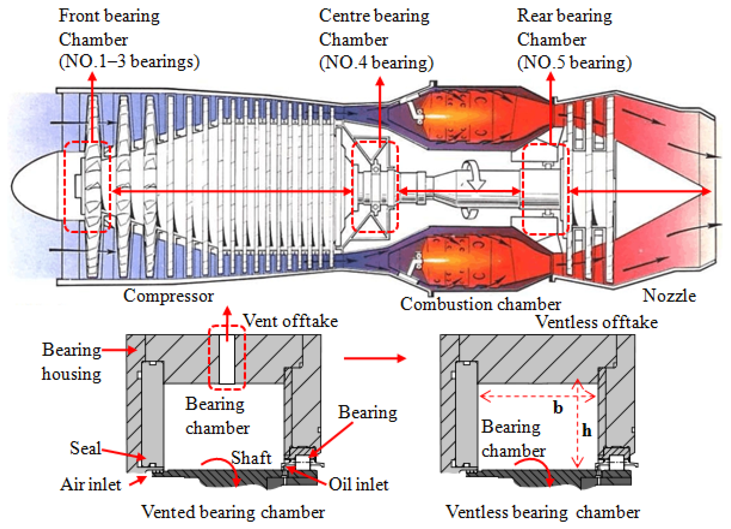
b is the chamber axial length, and
h is the chamber radial height.
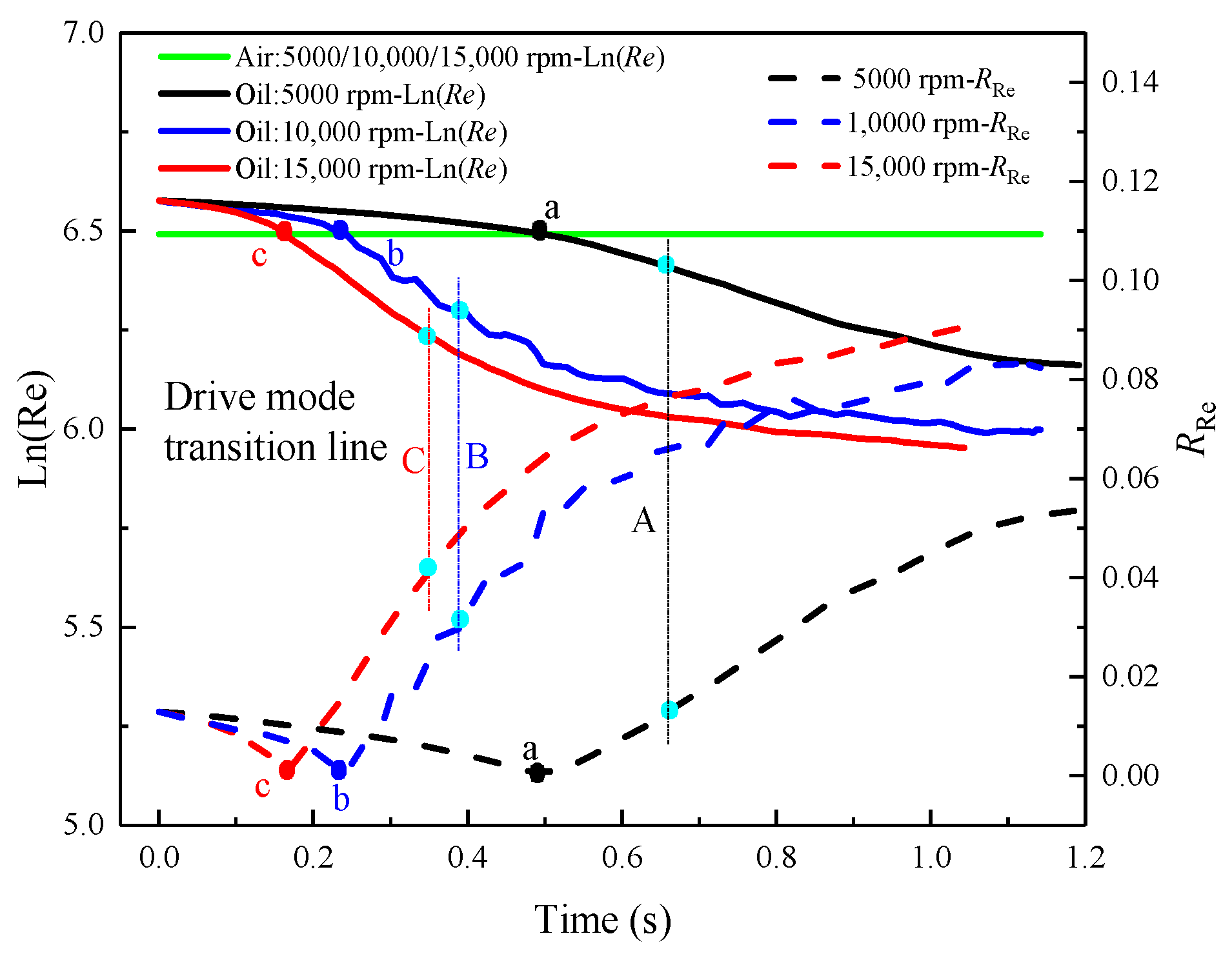
The evolution of the Reynolds number over time is shown in
Figure 7. It can be seen from
Figure 7 that the oil Reynolds number decreases over time and then levels off under the aspect ratio of 0.712. At the initial stage, the viscosity of lubricating oil after heat transfer is small and the Reynolds number is large due to the high temperature of the chamber. The flow of oil/gas two-phase is mainly affected by the rotor speed, which is called the rotational speed driving mode [
15]. Thus, the Reynolds numbers of air and oil are equal for three rotor speeds owing to the shear force of the rotor. Moreover, the variation range of the natural log-Reynolds number of oil is symmetrically up and down based on the natural log-Reynolds number of air before the driving mode transition points (A, B, and C). Then, the natural log-Reynolds number of oil decreases over time after points A, B, and C. The viscosity of oil increases with decreasing average temperature in the chamber. Therefore, it is more susceptible to the impact of the rotor shear force compared with air and forms a single vortex dominated by lubricating oil. Here, the Reynolds ratio of two phases can be used as the criterion of the driving mode, which is as follows:
The dotted line in
Figure 7 shows the Reynolds ratio (
) over time under the aspect ratio of 0.712. At 5000 rpm, 0
0.01373 and 0.01373
are the rotational speed driving mode and the lubricating oil drive mode, respectively. At 10,000 rpm, 0
0.02963 is the rotational speed driving mode, and 0.02963
is the lubricating oil drive mode. At 15,000 rpm, 0
0.03965 is the rotational speed driving mode, and 0.03965
is the lubricating oil drive mode.
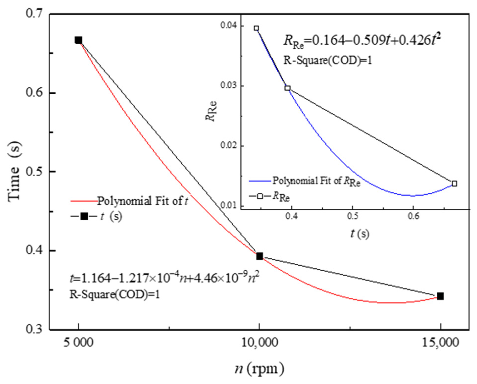
As shown in
Figure 7, the higher the rotational speed is, the higher the
is, and the shorter the time reaches the mode transition point. However, it is not convenient to use
as a criterion of the driving mode transition since it varies with the rotor speed. As shown in
Figure 8, the correlation between rotor speeds (
n) and
is proposed according to the simulation results, which is as follows:
Meanwhile, time (
t) and
obtained at different speeds are also fitted as follows:
Substituting Equation (21) into Equation (22), the correlation equation can be obtained as follows:
Table 2 shows the comparison between the simulated results and the calculated values of Equation (23), and it can be seen that the error is small. Thus, the driving mode criterion of the ventless bearing chamber at 5000 rpm ≤
n ≤ 15,000 rpm is as follows:
is the rotational speed driving mode with twin vortices and is the lubricating oil drive mode with a single vortex.
3.2. Three-Dimensional Flow Characteristics of Oil/Gas Two-Phase
The density of streamlines in the three-dimensional flow field within the same benchmark can reflect the velocity of air and lubricating oil at this moment. The fluid velocity in the dense area is large, and vice versa. At the same time, according to the turbulence intensity in the ventless bearing chamber, the intensity of the developed turbulence and the disturbance in the oil/gas two-phase flow in the bearing chamber can be characterized. At different times, when the turbulence intensity of oil/gas two-phase is small, there is a small trend of turbulence development. Because the Reynolds number of oil/gas in the chamber is inversely proportional to the turbulence intensity, compared with the viscous force, the inertia force has a larger effect, and the trend of turbulence developing in the flow field decreases, and the degree of disturbance of oil/gas two-phase reaches a larger value. For the turbulence intensity (
I) of oil/gas two-phase in the bearing chamber, the formula is as follows:
The turbulence intensity (
I) is defined as the ratio of the root-mean-square of the velocity fluctuations (
) to the mean flow velocity of oil/gas two-phase (
), and
is the Reynolds number of oil/gas two-phase flow under the hydraulic diameter in the bearing chamber. The turbulence intensity is determined by calculating the Reynolds number of the hydraulic diameter in the bearing chamber. The Reynolds number can be calculated as follows:
where,
is the average density of the oil/gas two-phase in the bearing chamber, and
is the average dynamic viscosity of the oil/gas two-phase. The three-dimensional flow of oil/gas two-phase in the ventless bearing chamber is characterized by the velocity value and turbulence intensity.
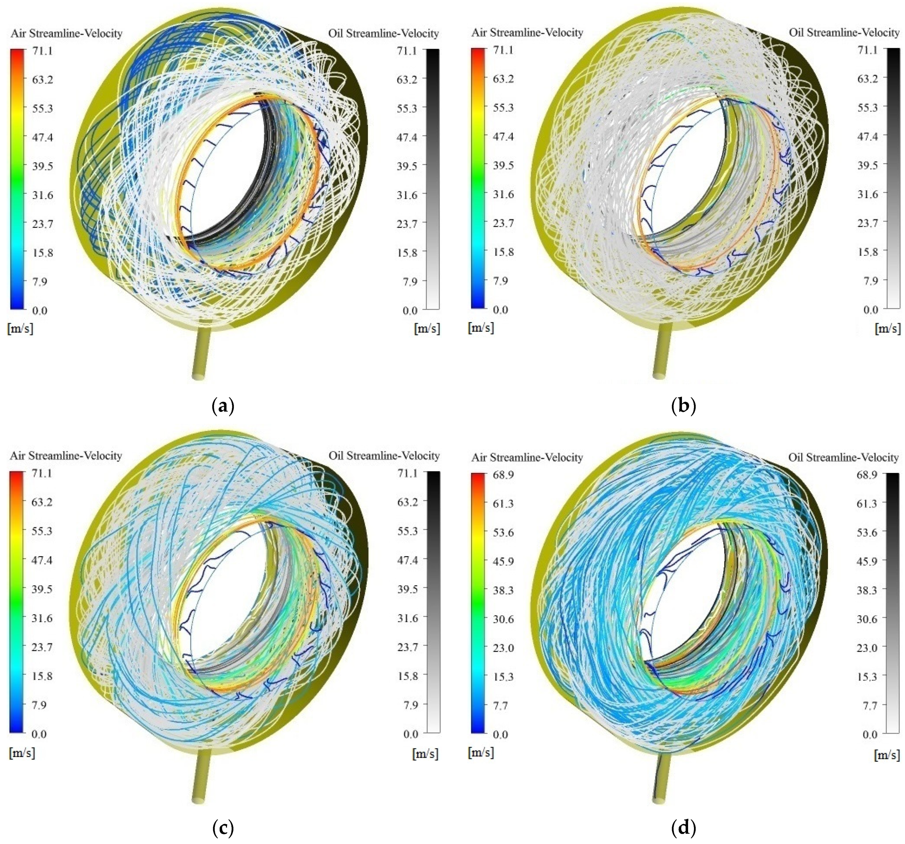
Figure 9 shows the shows the oil/gas streamlines of the rotational speed driving mode at 10,000 rpm. Twenty-five equidistant streamlines at the interface between the air inlet and oil inlet are selected, respectively, where the colored lines are the air streamlines and the gray lines are the oil streamlines. These are the streamlines of the oil/gas two-phase in the unsteady process, and also represent the evolution of the twin-vortex circulations in the three-dimensional chamber. As it can be seen, when the aspect ratio of the bearing chamber is 0.712, oil and air have low velocities at 0.056 s, and the streamlines of oil and air are interleaved with each other. The velocity of oil/gas two-phase is 5.08 m/s by monitoring the velocity change of oil/gas two-phase, and the turbulence intensity of the flow in the chamber is 8.69%. The actual vorticity value at the same vorticity level can indicate the vortex intensity in the flow field. At this point, the actual value of vorticity obtained by selecting a vorticity level of 0.05 is 4708.8 s
−1.Then, the oil gradually dominates and fills the whole bearing chamber at 0.198 s, while the air streamline is almost non-existent in the chamber and only serves as a sealing role, and the pitch of the twin-vortex circulations decreases. The streamlines of oil/gas two-phase become dense, the average velocity of oil/gas two-phase increases to 10.70 m/s, the turbulence intensity of the flow in the chamber is 7.89%, and the average value of vortex in the bearing chamber is 4889.2 s
−1. The vorticity value and the intensity of the vortex increases. In addition, the air streamlines become more in the chamber and the oil/gas velocities reach a maximum under the disturbance at 0.213 s and 11.13 m/s. The streamlines are the densest. At this point, the turbulence intensity of oil/gas two-phase flow in the ventless bearing chamber reaches the minimum value, which is 7.86%. In the unsteady process, the trend of turbulence development decreases from large to small, and the resistance of turbulence development increases. At this moment, the disturbance in the bearing chamber reaches the maximum and the value of vorticity reaches the maximum of 4966.5 s
−1. Then, the value of vorticity begins to decrease. At 0.303 s, the air streamlines increase in the chamber and are comparable to oil streamlines. At this time, the velocity of oil/gas two-phase decreases to 10.29 m/s, and the turbulence intensity in the chamber gradually increases to 7.87%. The pitch of the twin-vortex circulations in opposite spiral directions gradually increases, and the average value of vorticity in the bearing chamber is 4925.4 s
−1, reducing the vortex intensity. This is because the increase of air and lubricating oil retention increases the pressure in the chamber and reduces the velocity of the oil/gas two-phase, and the scrambled air streamlines appear on the air inlet side to prevent the leakage of lubricating oil from the air inlet to the other parts of the engine [
18].
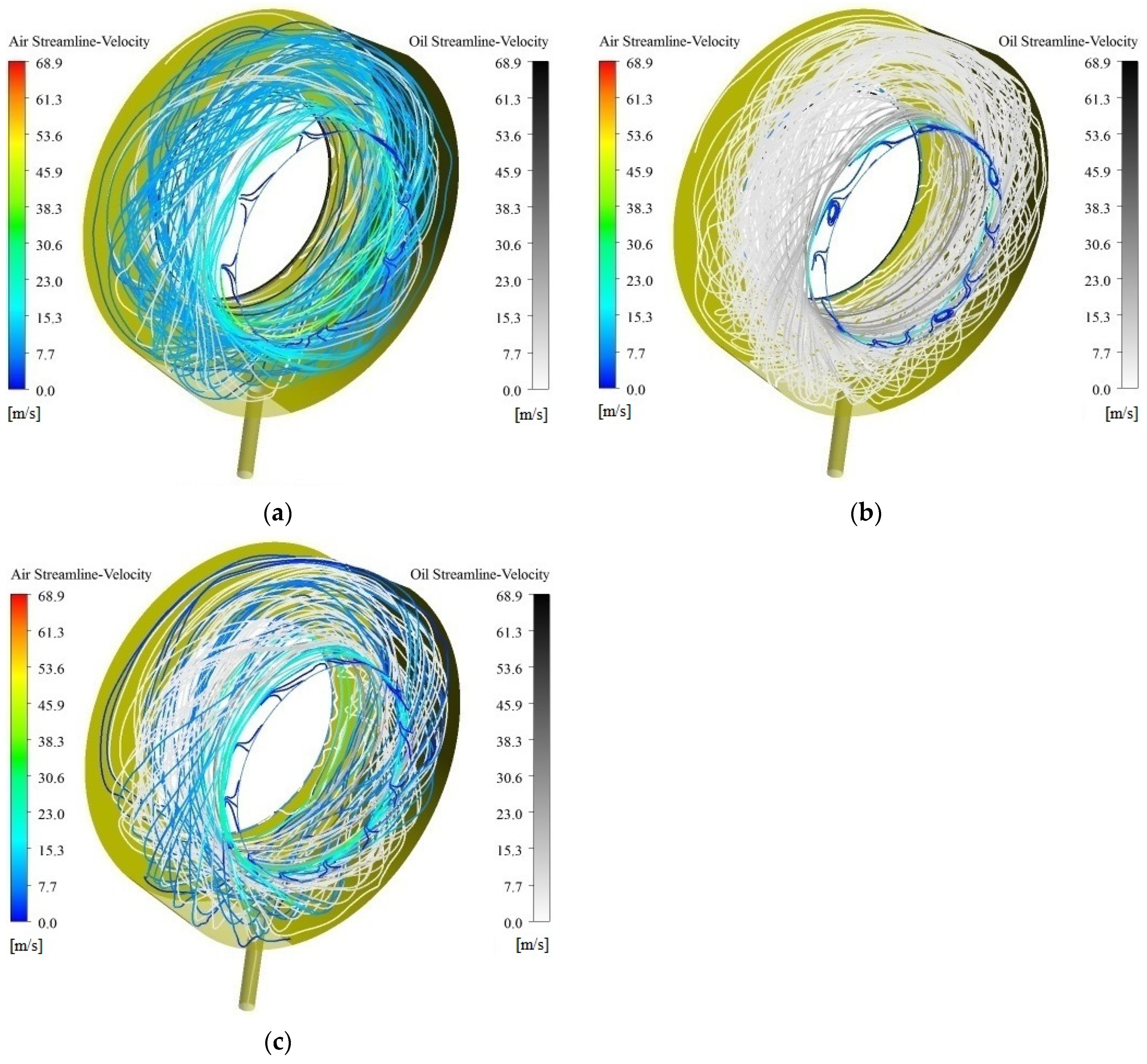
Figure 10 shows the oil/gas streamlines of the oil driving mode at 10,000 rpm under the aspect ratio of 0.712. The streamlines of the oil/gas two-phase flow decrease in the chamber, and there are almost no streamlines at the angle between the two sides, and a single vortex is formed in
Figure 10a. At this point, the average velocity of the oil/gas two-phase in the bearing chamber is 9.03 m/s, which further decreases, and the turbulence intensity of the oil/gas two-phase is 7.93%, indicating an increasing trend of turbulence development. Combined with the single vortex in
Figure 6d, there are small eddies at the four corners of chamber, and the tangential velocity of small eddies is low, which is not conducive to heat transfer. This shows that the flow characteristics of the oil/gas two-phase are the key factor for heat transfer between lubricating oil and the outer wall [
13,
19,
20]. At 0.588 s, air streamlines disappear, and the oil streamlines dominate the circumferential motion in the bearing chamber. At this time, the average velocity of the oil/gas two-phase in the bearing chamber is 6.9 m/s, and the turbulence intensity of the oil/gas two-phase is 8.12%. The trend of turbulence development further increases. Then, air and lubricating oil streamlines are mixed and the motion of oil/gas two-phase flow in the bearing chamber tend to be stable at 1.137 s, the average velocity of oil/gas two-phase in the bearing chamber is basically maintained at 5.7 m/s, and the turbulence intensity also reaches a constant value, basically at 8.2%. The average value of the vorticity in the bearing chamber is 4868.5 s
−1.
For the unsteady flow process at 5000 rpm and 15,000 rpm under the aspect ratio of 0.712, the process is basically consistent with 10,000 rpm, but the higher the speed, the shorter the time for the oil/gas two-phase to reach the mode transition point (twin vortices and a single vortex). The velocity of oil/gas two-phase and the turbulence intensity of oil/gas two-phase in the bearing chamber also changes. The higher the rotational speed is, the greater the value of the average velocity of oil/gas two-phase is in the bearing chamber, while the value of the turbulence intensity is relatively small. At 5000 rpm and 15,000 rpm, the average velocity of oil/gas two-phase reaches maximum values at 0.492 s and 0.162 s, which are 5.78 m/s and 15.96 m/s respectively. Meanwhile, there are increasingly dense streamlines of oil/gas two-phase in the bearing chamber. At 0.667 s and 0.342 s, the phenomenon of twin vortices changes to a single vortex at 5000 rpm and 15,000 rpm respectively, and the speed at this time is 5.22 m/s and 12.67 m/s, respectively. At high speeds, the number of streamlines of oil/as two-phase in the chamber at 10,000 rpm and 15,000 rpm decreases and then increases in the unsteady process, while 5000 rpm basically remains unchanged, which may be related to the change of pressure in the chamber. At 1.192 s of 5000 rpm and at 1.003 s of 15,000 rpm, the velocity is reduced to 3.47 m/s and 8.6 m/s respectively, and the turbulence intensity is 8.87% and 7.83% respectively, which gradually tends to be a steady state with running time. In the flow process of oil/gas two-phase, with increasing rotor speed, the streamlines at the included angle around the bearing chamber decrease. This is due to the shear force on the rotor wall, which leads to the tangential velocity of the oil and gas two phases increasing, and the radial velocity and axial velocity components being small. As a result, the turbulence intensity decreases when the rotational speed increases, the streamlines near the shaft wall are dense, and the streamlines move close to the rotor wall. The higher the rotational speed is, the more obvious this phenomenon is. Apart from the above factors, the increase in rotational speed leads to an increase in oil film thickness on the outer wall and the accumulation of lubricating oil in the chamber [
3], which reduces the flow volume of oil/gas two-phase.
3.3. Average Pressure and Velocity of Oil/Gas Two-Phase
In the transformation of driving mode, the average velocity and the average pressure values of oil/gas two-phase obviously change.
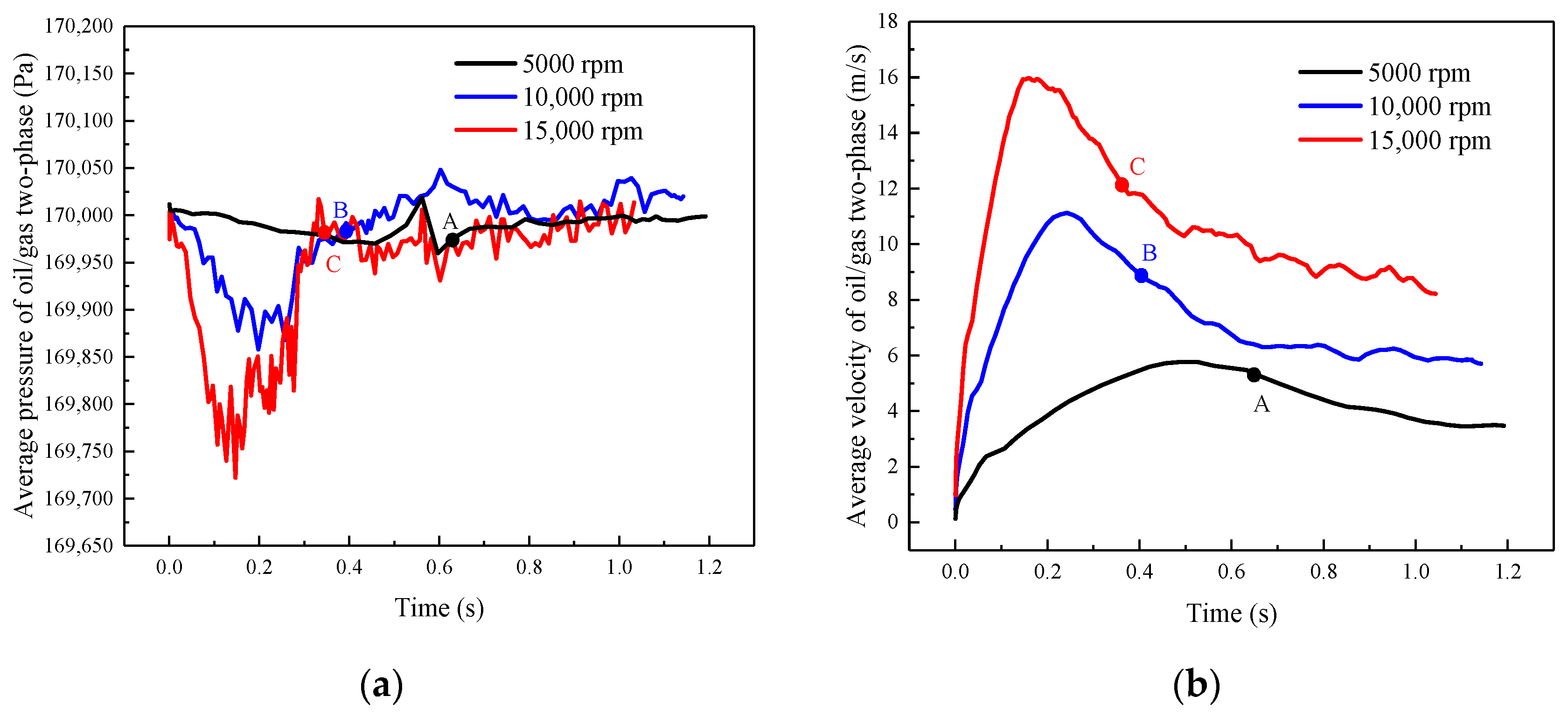
Figure 11 shows the relationship between average pressure (a) and average velocity (b) of oil/gas two-phase at different rotor speeds.
As shown in
Figure 11a, the average pressure of oil/gas two-phase under the aspect ratio of 0.712 at different rotor speeds first decreases and then increases before the points of a single vortex (A, B, and C), and finally tends to be stable. The average pressure of 15,000 rpm drops sooner and the decrease magnitudes are greater than 5000 rpm and 10,000 rpm, with the lowest value being 169.72 kPa at 0.147 s. The lowest values of 5000 rpm and 10,000 rpm are 169.98 kPa at 0.492 s and 169.86 kPa at 0.198 s, respectively. Since the oil and air flow into the bearing chamber at high-pressure values from the narrow oil inlet and air inlet, respectively, the volume of the two phases then expands, resulting in a decrease in the average pressure. After reaching the lowest value, the average pressure begins to increase owing to the retention of lubricating oil in the bearing chamber and tends to be stable after the single vortex point (A, B, and C), fluctuating at approximately 170 kPa, which may be the reason for the alternating phenomenon of the existence and disappearance of air streamlines in the chamber.
As shown in
Figure 11b, the average velocity under the aspect ratio of 0.712 first increases, then decreases and finally tends to be stable at different rotational speeds. The maximum velocities of 15,000 rpm and 10,000 rpm are 15.96 m/s and 11.13 m/s at 0.162 s and 0.213 s respectively, while the maximum velocity of 5000 rpm is 5.78 m/s at 0.492 s. However, because of the compressibility of air, the change of average velocity in the chamber lags behind the change in the average pressure. The lower the rotor speed is, the more moderate the changes of pressure and velocity in chamber are, indicating that the flow of air/oil tends to be stable faster at low speed.
3.4. Radial and Axial Flow of Oil/Gas Two-Phase
Figure 12 shows the axial variation of average velocity of oil/gas two-phase on the 0.07 m radius section at 10,000 rpm. The radius is 0.07 m, and it is close to the rotor wall under the aspect ratio of 0.712. As time goes on, the region with relatively large velocity of oil/gas two-phase at the section tends to the air inlet side. As shown in
Figure 12, the average velocity presents asymmetrical distribution of high in the middle and low on both sides at time ranges from 0.027 to 0.198 s, which is consistent with the distribution of the twin vortices in
Figure 6b. At the beginning, the velocity of the oil/gas is larger at 1/2b in the axial direction. The peak of velocity shifts to the air inlet side over time and gradually forms a single vortex, which is consistent with the evolution from the rotational speed driving mode to the oil driving mode. The peak of the velocity also firstly increases, then decreases, and then stabilizes. After reaching 0.393 s, the peak is at the inlet side, and the motion of oil/gas two-phase in the bearing chamber is integrated into a single vortex circulation.
Figure 13 shows the variation of the oil/gas average velocity at 45° cross section for different rotor speeds along with the aspect ratio of the bearing chamber. The velocity distribution is similar at different rotational speeds under the aspect ratio of 0.712, which can be partitioned into three zones: a severe drop zone from the inner wall of the rotor to
A1 (0~0.003), a steady zone from
A1 to
A2 (0.03~0.667), and a fast drop zone from
A2 to the outer wall of the chamber (0.667~0.712). Here, the average velocity of the oil/gas two-phase close to the inner wall of the rotor is large in the severe drop zone, and the velocity decreases sharply with the increasing radius. The thickness layer of the severe drop zone is small, mainly close to the rotor wall, and the cross-sectional area of the thickness layer accounts for 4.25% of the cross-sectional area. The average velocity in the steady zone is basically unchanged. This is mainly the flow domain of the vortex, where the oil/gas two-phase moves circumferentially in the form of a single-vortex circulation, spirally, with a large range, accounting for 89.36% of the cross-sectional areas. In the fast drop zone, the average velocity near the outer wall drops to zero under the action of the outerwall shear force, and this velocity change layer accounts for 6.39%.
3.5. Flow Characteristics of Lubricating Oil
Figure 14 shows the evolution of the oil distribution (
α = 0.25) and velocity fields at 10,000 rpm. As shown in
Figure 14, the oil is sprayed at an incident angle of 45° at 0.243 s, and some larger oil drops fall off and are thrown to the outer wall under the shear force on the rotor wall at 0.448 s. Then, the number of oil drops on the outer wall increases with the decrease of the oil drop volume, resulting in a gradually uniform circumferential distribution at 0.648 s, accompanied by a small amount of lubricating oil flowing out of the scavenging offtake at the bottom of the bearing chamber. The volume of oil drops becomes larger and the contact area with the outer wall increases with the accumulation of oil. Large drops gather at the bottom of the chamber since the shear force cannot offset the effect of gravity at 0.847 s. When the time is 1.057 s, the aggregation area is mainly located in the circumferential range of 135~180°. At
t = 1.142 s, an increasing number of oil drops adhere to the top of the outer wall and gradually stretch, showing a trend of forming an oil film. However, the tangential velocity of oil is small, and it is difficult to form a uniform oil film due to the influence of gravity.
The distributions of lubricating oil are mainly affected by the rotor shear force and oil phase gravity [
21,
22].
Figure 15 shows the distributions (
α = 0.25) and velocity fields of oil at different rotational speeds in the steady state. The oil drops mostly appear in blocks for 5000 rpm. There is a significant slipping of oil on the sidewall of oil inlet, and a large amount of lubricating oil accumulates at the bottom of the chamber in the circumferential range of 165~225°, with a symmetrical distribution, indicating that gravity plays a leading role. At 10,000 rpm, oil drops in the chamber are large in number and small in volume, and most of them are attached to the outer wall in flat spheres. The accumulation area at the bottom shifts circumferentially along the outer wall under the action of shear force. At 15,000 rpm, the oil drops are thrown to the outer wall at high velocity under the action of shear force, and the impact of airflow vertically entering the bearing chamber accentuates the oil drop ruptures. Therefore, a large number of thin-sheet oil drops are formed on the outer wall, the circumferential distributions of oil are more uniform, and the accumulation area at the bottom of the chamber disappears.
The Weber (
We) number is an important dimensionless parameter to characterize the droplet shape and is the ratio of inertia force to the surface tension. For oil drops in the bearing chamber, the
We is as follows:
where,
ug is the average velocity at the interface of oil/gas; and
σg is the surface tension coefficient of oil/gas.
Figure 16 shows the contour of the Weber number (
α = 0.25) at different rotor speeds in the steady state. The Weber number near the rotor is greater than 1, indicating that the inertia force is greater than the surface tension, and oil drops break soon after entering the bearing chamber. For 5000 rpm, the Weber number near the outlet of the bearing chamber is small, showing that the volume of oil drops is larger and that accumulation occurs. The Weber number on the outer wall of the chamber decreases with increasing rotor speed, and the oil forms a uniform oil film. The number of Weber at the corner of the outer wall of the bearing chamber is small, and lubricating oil easily accumulates. Attention should be given to oil deterioration or coked oil caused by poor heat transfer at this position [
13]. The circumferential distribution of oil becomes more uniform with the increasing rotor speed under the aspect ratio of 0.712. Therefore, the increase of speed is beneficial to the heat transfer of the bearing chamber [
23].


