Article

On the Feasibility of a Launcher-Deployable High-Altitude Airship: Effects of Design Constraints in an Optimal Sizing Framework

by
Carlo E.D. Riboldi
*,†,
Alberto Rolando
*,† and
Gregory Regazzoni
Dipartimento di Scienze e Tecnologie Aerospaziali, Politecnico di Milano, Via La Masa 34, 20156 Milan, Italy
*
Authors to whom correspondence should be addressed.
These authors contributed equally to this work.
Aerospace 2022, 9(4), 210; https://doi.org/10.3390/aerospace9040210
Submission received: 1 March 2022 / Revised: 25 March 2022 / Accepted: 7 April 2022 / Published: 11 April 2022
(This article belongs to the Special Issue Mission Analysis and Design of Lighter-than-Air Flying Vehicles)

Abstract

:
When ground observation or signal relaying in the vicinity of an unfriendly operative scenario are of interest, such as for military actions or disaster relief, high-altitude airships (HAA) offer some technical benefits. Featuring a milder cost and higher deployment flexibility with respect to lower-Earth orbit satellites, these platforms, often baptized as high-altitude pseudo-satellites (HAPS), operate sufficiently far from the ground to provide better imaging coverage and farther-reaching signal relaying than standard low-flying systems, such as aircraft or helicopters. Despite the atmospheric conditions in the higher atmosphere, they offer stable airstreams and highly-predictable solar energy density, thus ideally giving the chance of smooth operation for a prolonged period of time. The design of airships for the task is often conditioned by the need to go through the lower layers of the atmosphere, featuring less predictable and often unstable aerodynamics, during the climb to the target altitude. With the aim of simultaneously largely increasing the ease and quickness of platform deployment, removing most of the design constraints for the HAPS induced by the crossing of the lower atmosphere, and thus allowing for the design of a machine best suited to matching optimal performance at altitude, the deployment of the HAA by means of a missile is an interesting concept. However, since the HAA platform should take the role of a launcher payload, the feasibility of the mission is subject to a careful negotiation of specification, such that the ensuing overall weight of the airship is as low as possible. A preliminary design technique for high-altitude airships is therefore introduced initially, customized to some features typical to missile-assisted deployment, but with the potential for broader applications. The proposed procedure bends itself to the inclusion in an optimal framework, with the aim of seeking a design solution automatically. A validation of the adopted models and assumptions on existing HAPS is proposed first. The design of the airship is then carried out in a parameterized fashion, highlighting the impact of operative and technological constraints on the resulting sizing solutions. This allows for the marking of the boundaries of the space of design solutions for a launcher-deployable airship.

1. Introduction

Following the massive introduction of satellites to support the needs of imagery and signal relay missions, for commercial, humanitarian, and military purposes, platforms which feature a greater flexibility and meet the requirements for a lower-budget and quicker deployment have been in the scope of research [1,2].
The so-called high altitude pseudo-satellite (HAPS) concept, i.e., a flying craft stationed in the higher layers of the atmosphere where aerodynamic flight is still possible, typically between 18 and 25 km from the ground, can be managed by using very different crafts [3]. The high altitude allows one to take advantage of the good stability and predictability of airstreams [4], and the lower distance from the ground allows for operation with comparatively less sophisticated imagery and signal relay plants, while retaining or even surpassing the quality of the output of space satellites (for instance, a better absolute image resolution may be achieved with a lower-budget zoom lens). Furthermore, the more intense solar radiation at higher altitudes in the atmosphere allows solar power harvesting to be a very significant—even primary—contributor to the power balance of the flying craft, similarly to space platforms [5].
Since payload is at a premium when reaching an altitude that high, HAPS platforms are typically unmanned. Engineered realizations based on a winged configuration have been tested [6,7,8]. As it is known, winged aircraft require relative airspeed to remain airborne, and this creates the need for engines and the energy to feed them for the duration of the flight. This in turns limits the weight onboard which can be used for payload. Furthermore, the need for aircraft to keep moving constrains their ability to carry out fixed-point observation. Combined with limited—despite significant—endurance at the current technological level, this makes winged configurations largely sub-optimal for signal relay in support of disaster relief missions or continued fixed-point surveillance for military tasks.
Conversely, high-altitude airships (HAA) offer the advantage of a different method to counter weight, i.e., aerostatic force, which allows for a strong reduction in the power required for propulsion, thus enabling a comparatively larger payload weight for the same take-off weight [7,9]. Furthermore, provided they can face the airstream at altitude, HAA can be employed for fixed-point flight with good accuracy. A major shortcoming of every flying craft destined for station-keeping missions at higher altitudes (such as HAPS) is constituted by the need to go through more unstable and more dense layers of the atmosphere while flying towards the destination level [8,10]. To tackle this issue, missile-assisted deployment is an interesting alternative. However, the latter finds its more straightforward application when an HAA is considered being deployed at altitude, thanks to the ability to make the airship very compact when not inflated, thus making its size compatible with the typical size of candidate high-atmospheric missiles. Clearly, the adoption of a compact missile launcher for the deployment also adds to the quick response capability of the overall system, which is in good agreement with the typical requirements of disaster relief missions.
The chance to take the airship to the intended deployment altitude does impose a strict constraint, especially on weight, because the HAA has to be considered primarily as the payload of a missile. Consequently, the HAA needs to be conceived from preliminary sizing as a weight-minimal (i.e., weight-optimal) system. When the chosen missile is lighter, typically for the reason of increased transportability, that means a lower cost and increased ease of deployment. Furthermore, the constraint on the weight of the airship to be put onboard is more stringent.
Building on this concept, in this work the chance to cover a HAPS mission by means of a missile-deployed HAA is analyzed, with the aim of assessing its feasibility. With this goal, a focus has been put on a detailed preliminary design procedure of an airship for high-altitude operation. Besides the advantages of the low turbulence and good predictability of airstreams in the higher layers of the atmosphere, the high solar power harvesting opportunities, and the lack of any constraints due to the autonomous climb to the stationing altitude, comes the need to minimize weight and make it compatible with the payload of the lightest (i.e., cheapest and most easily transportable) low-atmospheric missiles.
The concept of a missile-assisted deployment of an HAA has been proposed in [11], showing its general validity, but making use of simplified models for energy balance and mass characterization without analyzing the effects of technology constraints on airship sizing.
Despite considerable efforts in the setup of design procedures for airships, leading to some consolidated approaches [12], in the current literature it is often pointed out that existing methodologies rarely allow a high degree of automation in the design process [13,14,15]. Furthermore, when analyzing the design of HAA, it is more generally treated as autonomously deployable (as opposed to launcher-deployable); the existing literature invariably makes use of strong assumptions and approximations on the environment and especially on the modeling of the wind and solar power radiation, both during ascent and at altitude [16,17,18,19,20]. When this is not crucial for the ascent phase, which in the concept of interest here is not faced by the airship itself (but by the missile instead), the effect of the choice of the stationing altitude, geographical position, and time of the year is extremely relevant for the resulting characteristics of the airship, including its weight, and this can potentially either allow or jeopardize the feasibility of the entire mission. Similarly, the geometry of the envelope and the technological features of the airship (including properties of materials) have been studied as sub-problems [21,22]. However, they were never thoroughly integrated into a complete design loop. Specifically, the weight was not looked at as a hard constraint and conclusions were not made on the feasibility of a launch-assisted deployment at altitude.
Therefore, despite previous research that is capable of providing useful direction, a comparative analysis of the feasibility of a launch-deployed HAA that gives a detailed description of the included realization technologies and of the environment at altitude needed for accurate predictions is still missing.
In this work, a complete preliminary sizing methodology is introduced first. This is based on two conceptual steps. In the first, a guess sizing is carried out based on the models described in the text, fed by a set of assigned variables, which need to be first guessed by the user. In a second step, the outcome of the sizing should be verified with respect to a set of major constraints. Thanks to the structure and information workflow envisaged in this procedure, the sizing loop can be fully automated and cast as the core of an optimization algorithm targeting the minimum weight of the airship. This has been considered as a natural choice, considering the entire HAA needs to fit in a missile and be lifted by its boosters. In an optimal approach, starting from a guess of a set of variable parameters, a sizing is carried out by running the loop, enabling the computation of the overall mass of the system (optimization target) and of the constraint violation, so that a new iteration can be started accordingly. The process is repeated until convergence to an optimal solution which satisfies all constraints.
The sizing loop has been validated in terms of the models and logic adopted, making use of the data of an existing HAA [14], accounting for the specifications of the chosen test bed with non-substantial amendments to the sizing procedure.
To the aim of understanding the effect of a negotiation of specifications on the feasibility of the missile-assisted deployment, the optimal sizing methodology has been employed to carry out the preliminary sizing of an HAA for a HAPS mission, in four selected test cases featuring very different geographical locations. This analysis highlights strong trends and dependencies, underlining the relevance of the choice of some of the design parameters, including the stationing altitude in combination with the geographical position. In particular, a strong effect on overall weight can be observed in some test cases. To better investigate mission feasibility, further analyses have been carried out, investigating the result of a choice of the technological parameters involved in the sizing. These show that a suitable combination of realistic technological choices enables advantages on overall weight, allowing for the fitting of the airship as a payload on a missile. However, other combinations of environmental conditions and technological choices do not bear feasible results, thus showing the paramount importance of the proposed systematic, critical approach to the analysis of design specifications.

2. Preliminary Sizing of a High-Altitude Airship: Introductory Concepts and Models for Design

A procedure for the preliminary sizing of a high-altitude airship (HAA) making use of solar power can be based on the simultaneous satisfaction of feasibility criteria, quantitatively defined according to three major drivers:
1.
Buoyancy-weight balance. The buoyant lift force generated by the lifting gas enclosed in the envelope has to be equal to the weight of all elements making the airship, including payload.
2.
Energy balance. The energy that is collected over the mission from the solar array has to be equal or higher than the total electrical energy required for the mission by the airship’s own systems and for operating the on-board payload.
3.
Limit stress compliance. The ultimate stress of the envelope material should not exceed the estimated limit load acting on it, amplified by a safety factor.
Similar to the case of fixed-wing aircraft, preliminary sizing is an iterative process, invariably requiring a starting guess.
The latter can be identified starting from a mission goal, identified in carrying an assumed payload (e.g., a sensor suite), which needs to work over an assigned time schedule. This produces a core component of the weight and energy/power requirements to be satisfied for the mission. Furthermore, the altitude (or altitude range) acceptable for the stationing of the airship will be similarly the result of the payload choice.
Further assumptions in the first guess involve the general arrangement of the airship envelope and a starting geometrical sizing. For an HAA based on solar cells, this step corresponds also to the definition of the surface of solar arrays. Merged with the time schedule, geographical location on Earth, and target altitude (or altitude range), this directly allows for the estimation of the ideal captured solar radiation. Combining geometrical information and mission schedule requirements—the latter especially with the aim of estimating the inside/outside pressure gradient, thus allowing for the assessment of the required thickness of the envelope material—the weight break-down of the entire airship can be computed. This allows for the estimation of the overall energy and power requirements. In turn, the first guess sizing allows for the triggering of the iterative procedure mentioned above, where criteria corresponding to the three drivers just introduced need to be simultaneously verified for an acceptable sizing.
Before going into detail concerning the sizing procedure just outlined, it should be pointed out that, in order to allow the quick definition of the preliminary sizing of an HAA, an automated, optimally oriented approach has been envisaged. Therefore, all considerations in the setup of the design loop have been formulated so as to avoid the need for human intervention in running the process. If on the one hand this may cut short some speculations, thus excluding some area in the space of design solutions a priori, on the other it also allows one to carry out sizing computations more quickly, so as to allow for the performance of sensitivity studies, understanding the effect of a change in the design specifications on the resulting characteristics of the airship.

2.1. Envelope Lofting

One of the first steps in the sizing of the airship is the definition of its geometric characteristics. The geometry of an airship bears a direct influence on all aspects governing its operation. Firstly, the power consumption is directly related to the experienced drag and thus to both the size and shape of the envelope, while solar power capture is affected by the shape of the envelope and the layout of the solar array laid on it, which determines the actual amount of incident radiation that is captured and converted into electric energy. Secondly, the buoyant lift force is a function of the envelope volume and is therefore affected by envelope geometry. Finally, the overall mass is the result of a number of contributions, with numerical values bound to the geometry and size of the airship.

2.1.1. Analytic Geometry of the Envelope

Considering HAA designed for a high-altitude pseudo-satellite (HAPS) mission, keeping the airship in a fixed position with respect to the ground, in the face of reasonably slow-varying (albeit intense) headwind, is performed by adopting an axial-symmetric geometry. As a matter of fact, for that type of mission the envelope geometry is typically based on a solid of revolution. In mathematical terms, these geometries can be assigned based on different modeling approaches [6,16,19,23]. In this work, in consideration of the applications which will be later presented (see Section 4), the low-drag bi-ellipsoidal shape designed by the NPL [19] is adopted, consisting of two semi-ellipsoids jointed at the maximum thickness longitudinal location. For this analytic geometry the envelope is completely defined by the overall length of the envelope L and its fineness ratio F R = L 2 b , with b minor semi-axis of the ellipsoid. However, it should be remarked that whatever the mathematical modeling, once the geometry of a solid of revolution is assigned, the corresponding features required for aerostatic, power capture, and structural integrity computations can be uniquely evaluated—namely, the fineness ratio F R , envelope volume V e n v and area A e n v of external surface, area of lateral projection A s i d e , and position of the buoyancy center BC .

2.1.2. Geometry of Solar Cells

In order to assess the solar power and energy capture, the relative positioning of solar cells with respect to the local radiation, as well as the absolute size of the panels, are needed inputs. Considering the seasonal change in the direction of sun radiation, as well as a specific positioning of the HAA at a lower or higher latitude, the problem of the positioning of solar cells arrays on the envelope surface—i.e., where to lay them—may not be solved with an always-valid solution. In other words, whether putting solar cells on top of the envelope or to the sides (i.e., the most commonly adopted solutions) would be an optimal choice that cannot be determined in general a priori. Therefore, a set of analytic quantities to define the coverage of the envelope with solar cells is introduced, keeping a further set of variables to be assigned in the sizing procedure. In a later section, it will be shown how to select the corresponding values, according to optimal criteria. It is assumed that the area covered with solar cells is always symmetric with respect to the vertical plane of symmetry of the airship. Furthermore, a set of two azimuthal ( θ i n , θ o u t ) and two longitudinal ( x l e , x t e ) coordinates uniquely defines the portion of the envelope surface covered by cells. Clearly, as mentioned, an area obtained by symmetry with respect to the vertical plane will also be correspondingly covered by cells. This is illustrated in Figure 1 for an example geometry.
Since the shape—in particular, the curvature—of the envelope may yield significant differences in the power-capturing ability of one portion or another of the overall surface of the envelope associated to solar cells, the latter is discretized according to the curved paving model [19,22], based on a suitable number of azimuthal and longitudinal elements. This should significantly increase the accuracy of the prediction of the capturing potential, with respect to more coarse methods [6,16,19,23].

2.2. Power Balance

Energy depletion on board the HAA can be imputed to three major power sinks, namely motion—or fixed-point keeping in the presence of wind—payload operation, and other plants (such as computers, sensors, actuators, etc.).

2.2.1. Power Required for Station Keeping

Concerning motion, for an HAA performing a HAPS mission it is typically desirable to stay in a near-fixed position with respect to a point on the ground, in spite of the airstream present at altitude in the stratosphere. In case this requirement is not strict, an optimal energetic strategy can be envisaged, where the airship moves upstream during the day, profiting from the higher solar power available, and drifts downstream during the night. This typically allows for the optimization of the battery mass required for energy storage and reduces the overall weight [2,24]. However, if precise positioning is at a premium, that can be ensured by a proper sizing of the batteries. This more stringent scenario is considered herein. For station keeping, the thrust F T produced by the propulsion system should balance the aerodynamic drag. Therefore, it is associated with the propulsive power P p r o p that can be computed according to Equation (1)
P p r o p = F T v = 1 2 ρ v 2 V e n v 2 / 3 C D ,
where v is the relative airspeed of the airstream with respect to the airship, ρ the density of air at altitude, V e n v the volume of the envelope, and C D the drag coefficient of the airship [12]. To estimate the latter, lumped parameter methods can be deployed, expressing its dependence on the actual geometry as a function of a few integral parameters, such as the fineness ratio [25,26], or it can be estimated with numerical codes, based on a discretization of the hull shape. The axial-symmetric envelope can be considered aligned with the airstream, thus working at a null angle of attack with respect to it. Considering a null dynamic lift component, the value of the lift coefficient is correspondingly null, and the drag coefficient value C D needed for the computation is just one value (i.e., that for a null angle of attack), instead of a function.
Considering a null relative motion of the airship with respect to the ground, the relative airspeed v in Equation (1) can be estimated based on that of the airstream only. The latter is computed in this research according to the Horizontal Wind Model (HWM) [4,27], where the components of the airstream average velocity vector are assigned up to an altitude of 500 km as a function of geographic location (coordinates), altitude, day of the year, solar local time, and geomagnetic activity.
The power supply designed for the propulsion actually needed is obtained accounting for power losses, namely due to the electric motor (typically including an electronic controller), gearbox, and propeller. Electric motors come as a natural choice with respect to fuel-burning units, allowing for an increased mechanical and plant simplicity (e.g., no fuel system is required), higher energy efficiency [28], and the chance to reload the corresponding energy storage, thanks to solar power harvesting. The elements of the power train just introduced are represented, respectively, by the efficiencies η m , η g , and η p , which in turn produce the power required for propulsion P r e q , p r o p in Equation (2)
P r e q , p r o p = P p r o p η m η g η p .

2.2.2. Power Required for Utilities

As pointed out, other power utilities onboard include the payload, associated to a power P p l , and further electrical systems, associated to P o t h e r . These can be modeled in a power balance by means of the nominal power required for their use, divided by corresponding efficiency factors η p l and η o t h e r , yielding the total power required, Equation (3)
P r e q = P r e q , p r o p + P p l η p l + P o t h e r η o t h e r .

2.2.3. Solar Power Harvesting

The power input to the system comes from the solar cells, geometrically described according to the assumptions in Section 2.1. In order to numerically compute the power input, it is first necessary to compute power capture. Considering the peculiarities of a HAPS station-keeping mission, where the attitude of the airship in 3D spaces can be considered constant with null pitch and roll, the only variable associated to a change is yaw ψ . The latter will be such to keep the airship aligned with the stratospheric airstream at altitude, and will be proportional to the local wind direction, an output of the HWM model [4,27] for a specific location.
With the attitude of the airship assigned with respect to the irradiation direction, for an assigned solar cell spacial geometry, the relative incidence and tilt angles of each discretized component on the assumed solar cells area can be computed. This can be cast as input to an irradiation model—the SMARTS model has been adopted in this research [5,29,30]—to obtain the spectral global irradiance E g and the corresponding broadband value I g on a component of a solar cell surface. Further inputs required by the SMARTS model include geographical inputs (altitude and zenith angle of the location) and time of the year (for eccentricity correction of extraterrestrial radiation).
The power coming from the i-th discretized component of a solar cell can be analytically expressed as in Equation (4),
P s c , i = η M P P T η p a c k η s c , i A i I g , i ,
where η M P P T is the efficiency of the maximum power point tracker (MPPT), η s c , i is the photoelectric conversion efficiency of the cell, A i is the effective area exposed to solar radiation for the i-th discretized cell, and I g , i the broadband irradiance previously introduced, evaluated for the i-th discretized component of the solar array. The further efficiency η p a c k appearing in Equation (4) represents the power decrease due to the wiring between adjoining cells [6].
The photoelectric conversion efficiency η s c , i depends on technological parameters, reflecting the technology of the solar cell, and environmental parameters. In this work, several technologies have been investigated, including CIGS, a-Si, and CdTe [31,32,33]. For each technology, nominal η s c values can be obtained, which need to be corrected on account of a few environmental parameters. The latter include:
1.
Temperature: η s c is typically linearly influenced by the temperature of the panel, and the coefficients of the linear function are specific to the technology of the cell [34,35,36]. The computation of the temperature of the panel can be carried out based on models, such as NOCT [31,34] or HOMER [36]. The latter has been adopted in this research, bearing the actual temperature of the panel based on the assumption of a steady-state equilibrium between the solar energy absorbed by the module on one hand and the electrical output plus the heat transfer to the surroundings on the other.
2.
Radiation spectrum: generally a weak dependence for top-tier solar cells technologies, it can be however simply taken into account according to the model presented in [37], where the pressure-corrected air mass is considered as an input.
3.
Radiation intensity: the actual intensity of the radiation I g affects photoelectric efficiency and may result in changes of the order of some percent units on its value. This dependence, featuring an optimum for a specific radiation intensity, is technology-specific, and can be modeled according to the model presented in [37], suitably tuned based on the specific technology in use.
Once all components P s c , i have been computed, considering the overall discretized solar cells area, the total value of captured power can be obtained through a direct sum over i, yielding
P s c = i P s c , i .

2.3. Structural Integrity

Since HAA are of interest, the assumption is to design the airship as a super-pressure system, meaning that the pressure differential between the lifting gas and atmospheric air is left free to change, according to daily temperature cycles of the lifting gas, in turn resulting from the cyclic change of the exposure to solar radiation. Therefore, the airship is designed so that at operating altitude and at night, i.e., when the coldest internal temperature occurs and the lifting gas is most contracted, the gas fills the whole envelope, also providing a pressure differential sufficient for preserving shape and envelope rigidity. Conversely, the maximum design internal pressure can be estimated from the maximum expected super heat.
In order to compute the stress on the envelope, three geometric parameters, namely the airship length L, fineness ratio F R , and envelope volume V e n v , and two environmental specifications, namely the operational altitude z and the maximum wind speed v, are required.
Stress computations on the envelope bear as a primary output a minimum and maximum pressure differential.

2.3.1. Minimum Pressure Differential

The minimum pressure differential is obtained in order to simultaneously satisfy three design objectives, namely:
1.
Nose caving. A criterion for granting a sufficient rigidity of the envelope, to avoid nose caving while station keeping in an airstream, is based on the evaluation of the dynamic pressure of the airstream, assuming it turns into a static pressure in the vicinity of the nose cone (ideally on its tip). A maximum airstream speed v max that the airship will encounter over its entire mission is introduced, and a safety factor of up to s N C = 50% [12] is typically adopted, thus yielding for this criterion [12,17,38]
Δ P n o s e - c a v i n g = s N C 1 2 ρ v max 2 .
It should be remarked that the choice of v max cannot be known precisely a priori, so a conservative estimation based on the available experience is assumed.
2.
Extreme aerodynamic bending. In order to ensure a sufficient rigidity all along the airship envelope, in the presence of aerodynamic loads pushing the ship from the sides, a minimum Δ P b e n d i n g can be obtained from an empirical relationship, accounting for the contributions of aerodynamics-induced bending and thrust. The former (aerodynamics-induced) can be obtained from the following relationship [12,17,39]
Δ M l a t = 0.02155 1 + ( F R 4 ) 0.5492 L 0.02 0.5 ρ u g v g V e n v L 0.25 ,
where u g is a gust speed, assigned as u g = 25 ft/s when v g is taken as the design maximum level flight airspeed (i.e., v g = v max ) or u g = 35 ft/s when v g is instead taken as the design airspeed for maximum gust intensity, defined as the minimum between 35 kt and 0.65 v . All calculations in this work have been performed in both cases, selecting the most demanding outcome.
The contribution due to thrust can be included directly in the model expressing the minimum pressure differential, yielding the overall side-load pressure differential threshold
Δ P s i d e - l o a d = 2 M l a t + F T b π b 3 ,
where F T is thrust and b is the top radius in the envelope geometry. It should be remarked that the value obtained from Equation (8) is a conservative estimation, since the pressure difference may be reduced by a dynamic suction effect, as well as a hydrostatic effect due to the difference in the density of the lifting gas and surrounding air [17,39]. Such corrections are typically mild however, and Equation (8) captures most of the actual value according to this criterion.
3.
Envelope shape consistency at the bottom. As a result of the vertical pressure gradient in the atmosphere, especially for larger airships, a vertical gradient of the pressure difference between the inner and outer sides of the envelope may be experienced as well, yielding in particular a lower pressure differential at the bottom of the envelope. A requirement on the pressure differential according to this criterion comes in the form
Δ P h y d r o s t a t i c + Δ P c o n s i s t e n c y 0 ρ + ρ l g g b + Δ P c o n s i s t e n c y 0 ,
where g is gravitational acceleration, ρ is the density of air, and ρ l g is the density of the lifting gas. The density of the lifting gas can be expressed as a function of the temperature, therefore yielding the following explicit expression for Δ P c o n s i s t e n c y ,
Δ P c o n s i s t e n c y = s C ρ k l g R l g + 1 k l g R a P T min g 0 b 1 k l g R l g + 1 k l g R a 1 T min g 0 b ,
where R l g and R a are gas kinematic constants of the lifting gas and air, respectively, k l g is the purity ratio of the lifting gas, and T min the minimum temperature expected along the temperature cycle considered for the design. Finally, s C is a safety factor.
The actual minimum pressure differential can be computed taking the most stringent outcome of the three criteria just introduced (Equations (6), (8) and (10)), thus yielding
Δ P min = max Δ P n o s e - c a v i n g , Δ P s i d e - l o a d , Δ P c o n s i s t e n c y .

2.3.2. Maximum Pressure Differential and Breaking Stress

Concerning the maximum pressure differential, since the volume of the envelope is fixed, as the temperature of the lifting gas varies throughout the day, its density cannot change. Therefore, the static pressure of the lifting gas varies proportionally to its temperature. The maximum expected differential pressure across the envelope skin can be predicted based on a reasonable assumption of the maximum super heat experienced by the lifting gas, while the airship operates at altitude. Several experimental studies have investigated a prediction for the super-heat maximum temperature [1,40,41,42,43,44,45]. In consideration of the HAA mission, a conservative (i.e., high) change of temperature of +50 K is hypothesized. Accordingly, the maximum pressure differential can be computed based on Equation (12),
Δ P max = T max T min P + Δ P min P ,
where P is the atmospheric pressure at altitude and T max and T min the maximum and minimum temperatures encountered over the time frame of the mission. From Equation (12), a corresponding tensile stress can be computed, translating the pressure differential Δ P max into a circumferential stress component (called hoop stress) and a longitudinal one, acting on the envelope skin. This is achieved through the following models [39]:
σ h o o p , max = Δ P max + C p 1 2 ρ v max 2 + ρ ρ l g g 0 b b , σ l o n g , max = Δ P max + C p 1 2 ρ v g 2 ρ ρ l g g 0 b b 2 + 2 M l a t + F T b 2 π b 2 ,
where C p is the pressure coefficient, which can be estimated based on basic aerodynamic prediction models [17].
The top value among the two in Equation (13) should be taken into account to yield the constraining value in the sizing process, properly modulated with a safety factor s σ . In analytic terms,
σ b r k = s σ max σ h o o p , max , σ l o n g , max ,
where σ b r k is the breaking stress computed based on the sizing. This quantity shall be verified in the sizing process with respect to the actual ultimate stress of the assumed material for the envelope, σ e n v .

2.4. Estimation of Mass Components

The estimation of the mass of the components of the airship can be carried out considering the following breakdown,
M = M p l + M e n v + M f i n s + M c u r t + M m + M p + M s c + M M P P T + M b a t + M l g + M t a n k + M g o n ,
where the components are, respectively, those pertaining to the payload, the envelope, fins and curtain suspensions, the motors and propellers, the solar cells, MPPT and batteries, those of the lifting gas and corresponding tank, and that of the gondola. Ballonets are not included since they are not considered in the current design, which calls for a fixed-altitude HAA, which does not need to go through atmospheric layers during deployment. Considering the concept of an HAA of interest here, to be deployed at altitude making use of a missile launcher, the estimation of the components in Equation (15) allows for the definition of the overall mass to be stored on board the launcher. Historical regressions and first-principle relationships allow one to carry out the computation of each component, and they have been selected according to the mission of interest in this research. They will be listed in the following paragraphs.

2.4.1. Envelope, Curtain Suspension, and Fins

The density of the material composing the envelope and fins has been hypothesized to be identical, i.e., ρ e n v = ρ f i n s [6,17,21]. The value of the material specific density is a function of the technology of the fabric, and it is related to the tensile strength to be supported. Multiple layers of the same material produce an increase in the top stress supported, at the price of a higher density. The relationship between density and ultimate stress is linear [12]. The stress to be supported can be computed according to the points outlined in Section 2.3. The corresponding surface density is obtained from the relationship [6,17,21]
ρ e n v = k 1 σ g + k 2 ,
where k 1 and k 2 are typical to a material, and σ can be computed based on Equation (13). Clearly, the mass of the envelope can be computed as
M e n v = s e n v ρ e n v A e n v ,
where s e n v is a safety factor.
The size of the fin is typically a function of the volume of the airship. The historical regression method proposed in [6] is adopted in this research. It considers the relationship between the total fin area and airship volume of a number of existing airships, to establish a ratio of fin-area-to-airship-volume, which comes out as R f a = 0.0121 m−1. This method has been compared with the outcome of the volume coefficient approach [12], finding a good accordance for envelope volumes ranging between 5000 m3 and 40,000 m3, when the distance between the airship center of gravity and the quarter chord of the vertical/horizontal tail mean aerodynamic chord is assumed to be between 30% and 40% of the length of the airship. Hence, the mass of the fins can be predicted as
M f i n = k f i n ρ f i n A f i n = k f i n ρ f i n R f a V e n v ,
where k f i n is a factor which accounts for the internal reinforcements (cover tape, internal structure tape, spar fabric curtains, etc.) and the increase of mass due to manufacturing. According to the literature [6,17,19,21], a factor of k f i n = 2, a fairly conservative assumption, can be assumed for the inflatable fins of the HAA design of interest in this work.
Finally, the mass of the curtain load suspension system is given once again by the product between the fabric area density and the area of the curtain, which is estimated according to the method suggested for non-rigid airships in [12]. The curtain surface can be assumed equal to 20% of the envelope side projected area A s i d e , already introduced as a geometric specification for an assigned envelope geometry. Considering as usual a safety factor k c u r t = 1.06 [12], to account for assembly joints, the mass of the suspension system is written as
M c u r t = k c u r t ρ c u r t A c u r t = 0.2 k c u r t ρ c u r t A s i d e .
As previously observed, no ballonets are envisaged for deployment on the HAA of interest here. Most notable examples of HAA for HAPS missions actually do not make use of this system [46,47].

2.4.2. Motor and Propeller

A natural choice for HAA, which benefit from the high level of irradiance typical to the higher layers of the atmosphere, a purely electrical motor plant is assumed for the mission. The relationship between the power and weight of electric motors in the range of interest for aeronautical applications has been investigated in previous research [48,49]. The relationship between the two quantities can be assumed linear. In order to estimate the weight of the electric motor, the value of the maximum required power is therefore needed. This can be computed as
P m o t o r , max = 1 2 ρ v max 3 V e n v 2 / 3 C D η g η p .
Correspondingly, the weight of the electric motor is
M m = P m o t o r , max d m + c m ,
where coefficients d m , c m can be obtained from the literature or by proper regression of a pertinent motor database [49]. A similar approach has been adopted for the weight of the propeller, since a linear relationship exists between the logarithm of maximum propeller power and propeller mass. This is analytically modeled through coefficient w p . Therefore,
M p = P m o t o r , max w p .
Both the motor and propeller weights can be increased through multiplication by a factor w m > 1 to account for engine mounting.

2.4.3. Solar Cells, MPPT, and Batteries

The estimation of the weight of the solar cells, and of the MPPT required for cells operation, can be simply carried out introducing a mass density for the former and a mass-to-power ratio for the latter. Consequently, for solar cells a mass of
M s c = ρ s c A s c w s c ,
where ρ s c is the surface mass density of the cells and w s c a correction factor taking into account collectors, grid network, and other electronic and auxiliary components [17,21,50]. For the MPPT, the top power value associated to any of the cells P s c , max is the driver for the corresponding mass. A mass-to-power ratio w M P P T is introduced [50], such that
M M P P T = w M P P T P s c , max .
Concerning the batteries, these are required primarily to store a sufficient amount of energy for nighttime operations of the HAA, taking into account the need to feed the system in peak power conditions. An accurate computation in this sense is typically not carried out in airship design, leading to fairly inaccurate predictions of the energy storage mass. In the present work, an accurate closed-cycle model for the 24-h energy balance of the airship is proposed. According to this model, the required energy storage Q for continuous operation of the system is given by the integral in Equation (25)
Q = 0 24 h ω d n s p w r P r e q P s c η d s c h η t r η s w d t ,
where it is assumed that one will compute the maximum energy which should be stored in the batteries by computing an integral over a day of operations of the difference between the power captured by the solar cells and the power required by the system for work. The term ω d n is a binary factor with the function of distinguishing between time instants when the solar array output is sufficient to power the airship from those when it is not; therefore, the contribution of the energy storage system is needed to feed the airship plants. Furthermore, s p w r is a safety factor to slightly upscale the whole power system, making it able to cope with peaks in power demand or uncertainties, due for instance to lower-than-expected power generation, unpredictably excessive airstream speeds, or an airship orientation misaligned with respect to the stream direction. A value of s p w r = 1.1 is assumed [12]. The terms which appear in the denominator in Equation (25) are the discharge efficiency η d s c h of the energy storage system and the transmission and power switch/step efficiencies, η t r and η s w , respectively, which account for the line losses downstream of the system.
Based on Equation (25), the mass of the energy storage system can be predicted by simultaneously taking into account two competing sizing drivers, namely the need to store the amount of electrical energy required for nighttime operation and the need to satisfy any power demand of the platform, meaning that the peak discharge power must be greater than or equal to the maximum power requirement. This way of reasoning, already applied to the field of electrically-propelled fixed-wing aircraft [48,49,51], can be put in analytic terms as per Equation (26)
M b a t = max Q η d o d q b a t , ω d n s p w r P r e q P s c p d s c h
where η d o d is the depth-of-discharge or the fraction of actual discharge capability relative to the overall capacity of the energy storage system, and q b a t and p d s c h are, respectively, the specific energy and the specific discharge power of the battery.
Having defined the required mass of the batteries, or in general of the energy storage system, in order to collect sufficient energy for continuous operation, the closed-cycle model for the 24-h energy balance of the airship can now be completed, by also evaluating the surplus energy available for storage during daytime. Not all the excess power produced by the solar array is taken into account for the energy balance, but consistently with the concepts just introduced, the actual maximum continuous charge rate of the system is considered. Stated another way, if the power production of the solar array presents a peak that exceeds the charge rate of the system, the latter will limit the energy actually added to the system. As a result, the surplus energy effectively available for storage is given by Equation (27),
Q e x c = 0 24 h min 1 ω d n P s c s p w r P r e q η d s c h η t r η s w , M b a t p c h d t ,
where p c h is the battery specific charging power.

2.4.4. Gondola

The mass of the gondola, which is the part of the airship mainly devoted to the storage of the payload, batteries, and in general all subsystems required for control, navigation, and operation, can be put into a relationship with the corresponding masses, as per Equation (28),
M g o n = s g o n w g o n M p l + M b a t
where the sensitivity w g o n = 0.15 is introduced [12]. In addition, a safety factor s g o n is included in order to oversize the gondola and take into account a possible increase of mass due to ancillary components, such as pipelines, wires, and cables, as well as attachments of the gondola to the hull. By default, a 20% increase is considered; thus, a s g o n = 1.2 is assumed [12].
It may be pointed out that, with respect to the existing literature, recent research on multi-functional materials [52], and in particular structural batteries, allows one to envisage an at least partial fusion between the gondola structure and the energy storage system. This would be especially interesting in this specific application, since the loads that are to be carried by the gondola should be lower than on the fuselage of aircraft of comparable weight, and they are expected to be generally quasi-steady and highly predictable in the specific application of an HAA. What advantages the inclusion of this technology would bear on the mass of the airship has to be assessed. This investigation has been left to a future development of the present work.

2.4.5. Lifting Gas and Tank

The lifting gas typically adopted on board airships is either helium or hydrogen. The evaluation of the actual mass of the lifting gas onboard is made straightforward by the knowledge of the volume required for inflation V e n v and of the density of the lifting gas ρ l g , which is determined as a function of temperature, similar to Equation (10). Consequently, the following definition can be applied
M l g = ρ l g V e n v .
Since the airship is intended to be lifted to the stationing altitude by means of a missile, a set of pressurized tanks capable of storing the entire mass of the lifting gas M l g up to the stationing altitude, where the HAA will be inflated and released, needs to be taken into account in the missile payload mass. A model for defining the corresponding mass M t a n k has been taken from the consolidated design practice of hydrogen fuel cells, which need to similarly store relevant masses of hydrogen inside a tank, usually facing volume constraints (fuel cells are currently mostly adopted in transport vehicles) [53,54]. The gravimetric index K t a n k can be defined as
K t a n k = M l g M t a n k + M l g ,
and is a technological parameter typical to the chosen gas. The value of K t a n k for the lightest gases (hydrogen, helium) is unfavorable, ranging between 4.2% and 5.8%, thus implying a significant mass of the tank for storing a very limited mass of gas [53,54]. However, according to Equation (30), it is possible to find an explicit definition of M t a n k . Therefore,
M t a n k = s t a n k K t a n k 1 1 M l g .
A correction factor s t a n k is added especially to take into account the presence of a residual lifting gas in the tank, due to the decrease in the pressure differential while the tank is emptied to inflate the airship envelope, leading to equalization and to the usually incomplete expulsion of the lifting gas from the tank.

3. Sizing Algorithm: An Optimal Approach

As outlined in the introduction (Section 1), based on the estimation models presented in the previous Section 2, it is now possible to envisage the complete structure of a sizing loop. As stated when introducing models correlating sizing parameters to one another, special attention has been devoted to the formulation of the sizing problem so as to allow an automatic search of an optimal solution, driven by a general requirement on the minimization of a cost function, while granting the satisfaction of a set of suitable constraints.

3.1. Iteration Workflow

The workflow of the sizing process is introduced in Figure 2. Correspondingly, the flow along a single sizing loop, to be ideally performed in the seek for the optimum of a certain merit function, can be retraced schematically. In the figure, cyan blocks refer to data which need to be guessed or assigned, blue blocks to quantities computed based on the models presented in Section 2, and purple blocks to relevant sizing outputs. The latter are the result of a sizing loop. Based on them, the double-circled pink block to the bottom of the figure ideally represents the comparison of the output of a sizing loop with respect to constraints. This and the chosen objective function (in the present case, total mass) produce an adjustment of the geometry and allow one to run a further iteration (see Section 3.2).
A set of quantities related to the mission (Mission parameters block in Figure 2) need to be assigned as constant, i.e., non-negotiable, parameters:
1.
Mass and power adsorbed by the payload, M p l and P p l .
2.
Geographical location, in terms of latitude λ , longitude ϕ , and stationing altitude z.
3.
Solar dates for the mission.
The geographical coordinates and the solar dates (points 2 and 3) are the required input for the evaluation of the intensity and direction of the solar radiation at altitude, which is a major input to compute the irradiance I g , and therefore power capture, through the model introduced in Equation (4). The computation of the solar radiation at altitude can be performed based on standard models and is not explicitly covered in this work [29]. In a similar fashion, given the geographical position of the airship and its altitude, an estimation of the airstream speed v and direction β w can be obtained from standard models for the higher levels of the atmosphere [4,27]. These computations are represented by the block Environmental conditions in Figure 2.
Further environmental parameters which are required for some of the later computations are the atmospheric pressure and temperature, which depend on the global positioning and solar date. The average density of air ρ and the maximum and minimum temperature T min and T max expected during the mission are environmental characteristics and do not depend on the actual sizing of the airship.
In order to assign the geometry, a set of parameters is needed. These are specified in the block Geometry parameters in Figure 2. As stated in Section 2.1, in this work a bi-ellipsoidal solid of revolution has been adopted, bearing a description of the envelope geometry by means of its length L and fineness ratio F R . With the geometry completely assigned, it is possible to compute the corresponding envelope volume and areas V e n v , A e n v , and A s i d e , as well as the position of the buoyancy center BC (block Envelope geometry in Figure 2). As mentioned, the parameters chosen for assigning the envelope geometry may be different from those chosen in this work, according to an alternative modeling choice in terms of analytic geometry (for instance, more suitable to model a specific shape of the envelope, as is the case for teardrop designs). However, for an assigned geometry, the corresponding values just listed (as well as the fineness ratio, in case it is not a specification as in the present case) can be always computed.
In order to complete the assignment of the geometry, the parameters describing the extension of solar cells on the corresponding portion of the surface of the envelope are also required. As explained in Section 2.1, this is equal to assigning four further scalar quantities, namely θ i n , θ o u t , x t e , and x l e (block Cells geometry in Figure 2).
Once the geometry of the envelope and cells has been assigned, and the atmospheric environment is quantitatively described, it is possible to compute the power captured and to complete the evaluation of the power needed. In mathematical terms, this translates into computing the power captured by the solar cells P s c (block Available power & energy) and the power required P r e q for keeping the airship in place in the airstream (block Required propulsion power), running the payload, and possibly any other subsystem onboard requiring a power expenditure (all components are included in the block Required power in Figure 2).
The quantities defined in the process of evaluating power balance allow for the triggering of the computation of the mass of several components in the design. Further required inputs for this step include technological features of the cells, battery, envelope, and lifting gas (block Properties of materials in Figure 2). With knowledge of the power captured and needed, it is possible to compute the instantaneous difference between the two, according to the schedule of the mission, i.e., how long it is going to last, and when it will take place in the solar calendar. This is an input to the computation of battery mass M b a t (Equation (26)). Similarly, when computing the power required for propulsion, the main input is obtained to compute the power of the motors, and therefore to size up the mass of the motors M m and propeller M p r o p (Equations (21) and (22)). The mass of the solar cells M s c is obtained directly from the assignment of their extension, and similarly the mass of the MPPT, M M P P T , can be computed from the power captured. These computations are included in block Energy-related mass in Figure 2.
The acquired knowledge of thrust F T , as well as the definition of the environment, including the minimum and maximum expected temperatures and pressures, allows for the computation of the stress the envelope needs to sustain itself (Equation (13), block Envelope stress). This in turn allows for the completion of the computation of mass M e n v , and similarly of those of the fin and of the suspension system, M f i n and M c u r t (Equations (17)–(19); all computations are included in block Envelope-related mass).
Finally, the mass of the gondola M g o n and of the lifting gas and tank, M l g and M t a n k , can be computed based on the corresponding geometrical assignments, as explained in Section 2.4.5.
Table 1 summarizes the fixed technological parameters which are required for computing the mass components. The corresponding numerical values reported therein refer to the reference sizing example presented in Section 4.2. It should be remarked that the super-cold and super-hot temperature changes are such that T min = T + Δ T c o l d and T max = T + Δ T h o t , i.e., they should be added to the average atmospheric temperature at altitude.

3.2. Optimal Approach

The workflow described in the previous section can be adopted to run an optimal sizing problem, where the target of the optimization is that of minimizing the overall mass of the system. This is especially relevant for the intended mission profile of the HAA under study, since the entire airship should constitute the payload of a missile.
In analytic terms, the optimal problem can be formulated as
min p M s . t . c , b
where M has been defined in Equation (15), optimization parameters p are expressed by
p = L , F R , x l e , x t e , θ i n , θ o u t
and the sets of constraints and bounds, c and b , are defined as follows,
c : M a i r s h i p ρ e n v V e n v 0 Q Q e x c 0 x t e L + 2 0 x l e x t e 0 θ i n θ o u t 0 F R F R max 0 F R + F R min 0 , b : L min L L max x l e , min x l e L max x t e , min x t e L max 0 θ i n π 0 θ o u t π .
The first two inequality constraints in c are non-linear with respect to the optimization parameters and require a minimum lifting action from envelope buoyancy and a minimum energy storage capacity from the batteries. As can be noticed from Equation (34), the mass that needs to be sustained by the airship at altitude is not that of the entire system M. The latter is of course targeted in the optimization since it is the payload of the missile launcher. However, it is hypothesized that the tanks of the lifting gas are left on the launcher following inflation, thus reducing the required lifting force by a due amount. Actually, as will be clear from the results, that reduction in the lifting requirement from M to M a i r s h i p —where the latter is the mass of the HAA, without the tanks—is rather dramatic, since the mass of the tanks M t a n k is one of the primary components of the overall mass of the system in the presented study cases.
The other constraints in c (Equation (34)) are linear in the parameters and enforce consistency between different geometric variables defining the shape of the airship, consistency between longitudinal coordinates of the solar array segments and length of the airship, consistency between leading edge and trailing edge coordinates as well as inner and outer central angles of the same segment, and finally consistency between the longitudinal and angular coordinates of different segments, so as to avoid overlapping. The fineness ratio is constrained between values F R min and F R max , chosen so as to avoid unrealistic geometries. Similarly, the bounds on the optimization variables in set b help to prevent unrealistic sizing solutions.
The continuity and regular shape of the merit function and constraining equations in Equation (32) make the optimal problem ideally trackable by means of a gradient-based algorithm. This was adopted with largely satisfactory results (both in terms of optimum resolution and machine-time) working on the test cases presented in the next sections.

4. Application Results

4.1. Validation of the Sizing Loop

Before launching the sizing algorithm within the body of an optimization, thus letting it search autonomously for a design solution, it is worth testing the models and assumptions which constitute one iteration of the sizing procedure on the data of an existing airship. The comparison between the actual sizing and the outcome of the design loop may support the validity of the latter for obtaining results in real field applications.
The test case chosen for this validation is the HiSentinel80. That was a single-use, non-rigid, fixed volume, single chamber airship, with inflatable tail fins and a recoverable equipment pod [13]. It was 199 ft (60.6 m) long and featured a 45.5 ft (13.9 m) diameter, for a total gas volume of 6846 m3, and its envelope was made of a lightweight Vectran® based material, including Nylon as the gas barrier [13,46]. The non-gaseous mass of the airship without payload was 1068 lbs (484.4 kg), while the helium mass was 212 lbs (96.3 kg) [46]. It was designed to operate at 65,000 ft (19,812 m) at an average cruise speed of 18 kts (9.3 m/s) and for a mission duration up to 24-h [13,
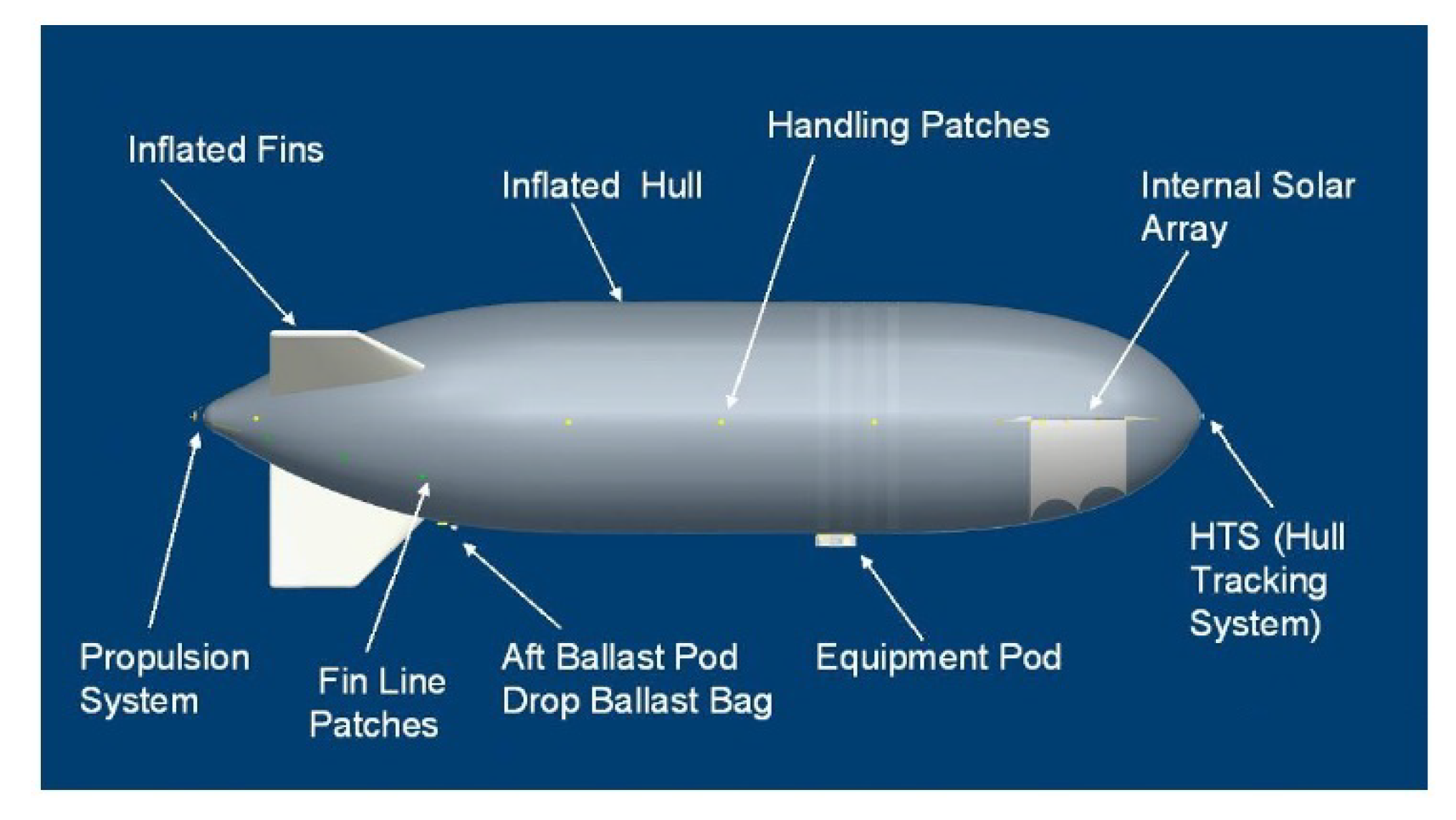
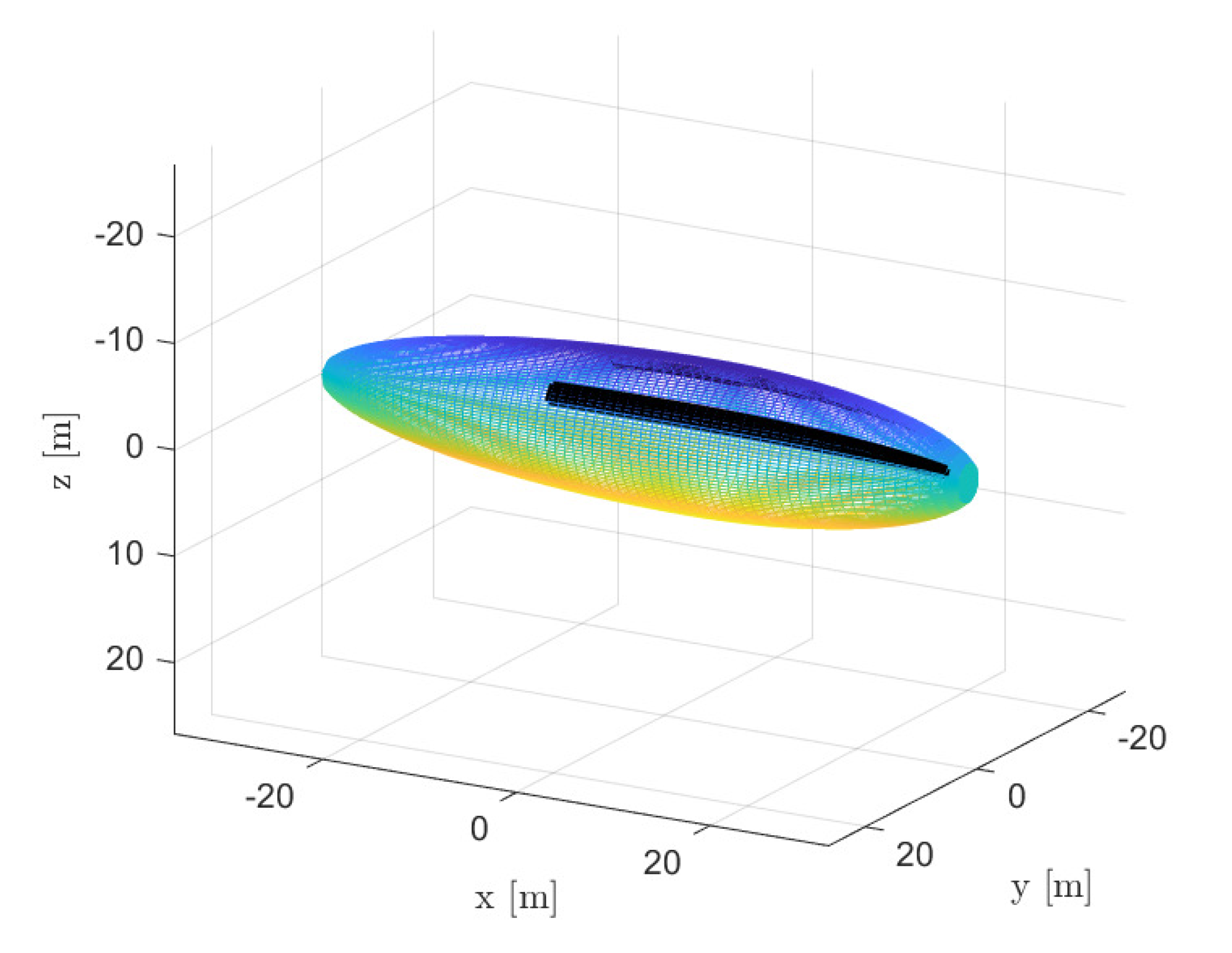
46]. Power was supplied by batteries supplemented by a non-pointed 1.2 kW thin-film, flexible photovoltaic array, mounted inside the hull near the nose (70% light transmission through the envelope). It was mounted as such to reach a horizontal configuration once at altitude, as depicted in Figure 3 [13,46]. Propulsion was provided by one tail-mounted electric-motor-driven propeller [13], and a minimum differential pressure exceeding 150 Pa was required across the envelope to eliminate buckling in the conical section at the propulsion strut ends [46].
Worst case loading of the hull was expected to occur during the day at a temperature close to 0 °C [46], while minimum helium temperatures in the order of 200 K were expected at nighttime [55].
The HiSentinel80 mission payload was housed in an insulated, cuboid container with dimensions 23-23-30 in. Passive heating and active, electrical heating maintained internal temperature when the payload was not powered. Otherwise, power dissipated by the payload during operation maintained the internal temperature. The payload housed a repeater, an Iridium transceiver, a high-resolution camera system, data storage, a high data rate transceiver, a GPS, an environmental monitoring package, a computer stack, and a power management and control subsystem, resulting in a payload mass of 86.2 lbs (39.1 kg) and a required power of 50 W [13,46].
Mission specifications for the design of the HiSentinel80 considered for the validation of the methodology are listed in Table 2. The location is assumed to be Page, Arizona, where the launch of the flight test performed on 10 November 2010 took place, and winter solstice is considered, as it is the most critical day of the year concerning solar energy harvesting. The airship had no ballonets.
Due to the lack of information on the HiSentinel80 concerning the technological part, as well as some specific features of this airship, assumptions were made in some cases, slightly modifying the procedure shown in the previous sections, justified a posteriori by the good results of the validation. In order to obtain a good agreement with the shape of the HiSentinel80 shown in Figure 3, a shape with a cylindrical mid-section is considered, instead of a bi-ellipsoid one. A specific value of prescribed minimum pressure differential has been taken into account, required to prevent buckling, an issue inherent to the HiSentinel80, thus substituting the computation of the corresponding threshold value. Concerning the envelope material, since it is a light-weight Vectran® based fabric, its sizing is performed considering the model derived by Carichner and Nicolai for Vectran® laminate [12]. Finally, further amendments pertain to the technological parameters of batteries and solar array. On account of the relatively older age of the airship, a low specific energy value of q b a t = 200 Wh/kg is considered for the batteries. Concerning the solar array, it is assumed that a-Si cells were employed, similar to other airships with a similar mission [15]. Consistently, proper values of area density and efficiency are assumed based on product data-sheets. Furthermore, in order to take into account the increase in mass due to the internal solar array assembly, which allows its horizontal deployment during ascent, also a higher value of the multiplicative factor w s c is assumed. The parameters modified with respect to the values in Table 1 for the purpose of validation are listed in Table 3.
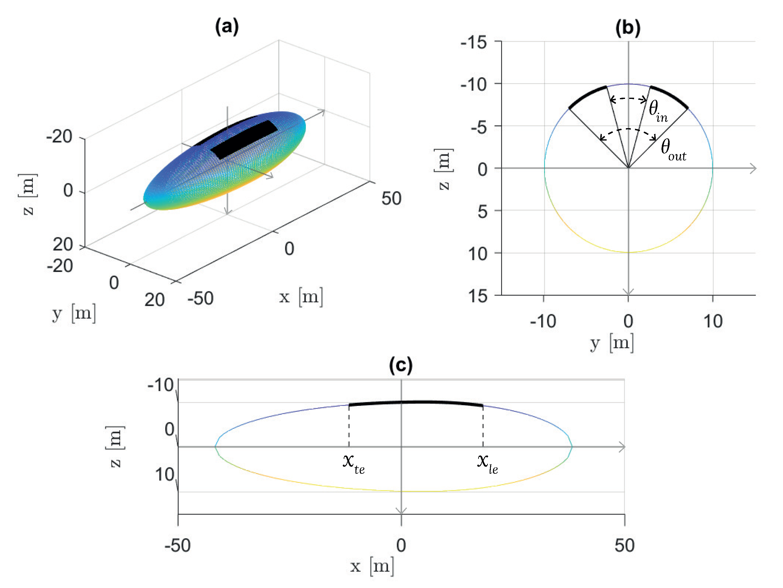
Concerning geometrical sizing, the length and fineness ratio of the HiSentinel80 are known, but the remaining information is not. Assuming, as stated, a geometry more resembling the actual one, proper values for the semi-axes of the rear and front semi-ellipsoids are then determined with a trial and error approach, with the goal of obtaining an envelope volume sufficiently close to the real one. Concerning the solar array, since it is not located on the hull surface as typically done in stratospheric airships, slight modifications are required with respect to the normal sizing methodology. The solar array arrangement can be modeled more simply as a single horizontal, rectangular array inside the hull. Consequently, θ i n and θ o u t are not assigned, and the solar array layout can be defined by the two longitudinal coordinates x l e and x t e , plus a half-width Δ y . Since the array is horizontal, its actual location inside the hull is not relevant to the incident solar radiation and power production calculations, so proper values for the three geometrical parameters are determined based on the required solar array area, which is known, and again considering the goal to obtain a good agreement with Figure 3. Indeed, knowing that the solar array has a nominal power of 1.2 kW, once efficiencies are assumed, the area of the solar cells array can be determined. A value of η s c = 8 % is assumed, and an area A s c = 15.002 m2 is obtained here, which corresponds with the actual value ( A s c = 15 m2). Values considered for the parameters defining the geometry of the airship and the arrangement of the solar array are listed in Table 4 (where a 1 and a 2 represent the characteristic dimensions of the envelope section), and the resulting layout considered for the validation is shown in Figure 4.
It is worth making a few more comments about some differences in how validation is here performed, with respect to the sizing loop introduced in Section 3.1.
Firstly, it is assumed that the system is sized in order to operate on a specific day and location, without satisfying the 24-h energy balance, that is, without respecting the constraint that the surplus energy generated by the solar array during daytime is sufficient to recharge batteries for nighttime operation, as required for more-than-one-day missions. In fact, since the HiSentinel80 is designed for a mission duration of up to one day, the need for battery recharge is not considered, and it is assumed that the system is sized such that the batteries, starting from a fully charged state, together with the solar array, can power the airship for 24 h.
Secondly, the wind speed profile is not computed from models, but an average cruise speed of 18 kts, reported by references for this specific airship, is considered to compute the required propulsive power. It was however verified that this airstream speed value is close to the prediction of the adopted HWM model. Next, in order to take into account the fact that the solar array is located inside the hull and only 70% of the radiation is transmitted through it, after the broadband global radiation is computed as explained in this work, its value is multiplied by a 0.7 safety factor.
A comparison between the known details about the HiSentinel80 design and the predictions produced by the sizing methodology is shown in Table 5.
In Table 5, M s o l i d is the total mass of the airship without gases, and M H e is the mass of helium onboard.
Despite the many uncertainties in the technological parameters, coped with by making reasonable assumptions and in some cases taking values from airships with a comparable mission, the results obtained confirm the reliability of the sizing approach and of the specific models which have been adopted.

4.2. Optimal Sizing and Parameter Analysis

The optimal approach introduced in Section 3.2 has been applied to a sizing scenario where an assigned HAPS mission payload of M p l = 10 kg, with a consumed power of P p l = 100 W, needs to be positioned and operated for one year at a fixed altitude of z = 20 km.
To better show how the automatic procedure can be exploited, four sizing problems have been solved, where the geographical position is chosen corresponding to four different locations, namely Pontianak (Indonesia), Port-au-Prince (Haiti), Houston (Texas), and L’Aquila (Italy), stricken by natural disasters over the last two decades. The corresponding coordinates vary significantly, as shown in Table 6.
Two remarks concern the settings of the sizing problem solved here.
The first is about the day of the year specified in the table. The sizing of a HAPS should be such to sustain operations over an unlimited time frame. This would require in principle the analysis of power balance over the intended time frame, taking into account the worst conditions of solar energy harvesting, due to seasonal change in irradiance especially at higher latitudes, combined with the worst wind intensity, which produces a higher power needed to keep the airship in position. In order to save on machine time, instead of analyzing the performance over the entire yearly calendar, the worst day is selected based on the worst (most intense) wind condition, which is typically the effect producing the more intense effect on sizing. A posteriori, the so-obtained sizing is checked on the day with the lowest overall solar power harvesting, in order to make sure that that sizing allows for the satisfaction of the power balance also in that case. If the latter turns out to require more than the one initially hypothesized, the representative day for the sizing is changed correspondingly. However, it should be noted that this way of proceeding is not substantial—it is of course possible to simply extend the time frame of the analysis from one day to one full year, without the need to do any crosschecks, at the price of some increase in the required machine time.
The second remark in Table 6 concerns the choice of the maximum airstream speed for station keeping v max which is chosen equal for all the sizing problems at hand, similarly to the stationing altitude. Specifically, the value chosen for speed is very conservative considering all four locations. This choice was made to allow a fairer comparison among the scenarios, which will be analyzed next.

4.2.1. Optimal Sizing at 20 km Stationing Altitude in a Single Location—Pontianak, Indonesia

In this paragraph, the complete sizing for the case of Pontianak will be shown, whereas in the next a summary and comparison of the results for all four considered geographical locations will be proposed.
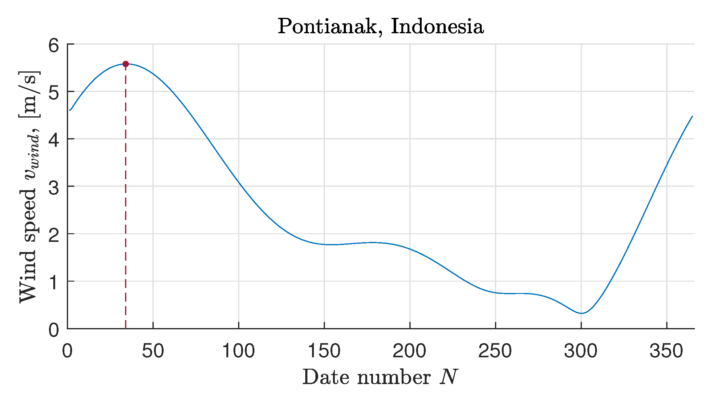
The first location, Pontianak, Indonesia, is located very close to the equator. The most critical day on which the design of the system is performed is identified according to the procedure illustrated in the previous paragraph. Figure 5 shows how wind speed varies throughout the year at 20 km altitude above Pontianak. Based on this annual wind profile, 3 February is initially selected as the day of the year that most requires the design.
The resulting sizing solution, however, proves to be incapable of meeting the 24-h energy demand on 26 January, when the energy available for storage is 2.37% less than what is required. Thus, 26 January is selected as a new design date. The definitive mission specifications for the design of the HAPS platform to operate continuously year-round at 20 km altitude above Pontianak have been reported in Table 6.
The values of the design variables output by the optimization algorithm are reported in
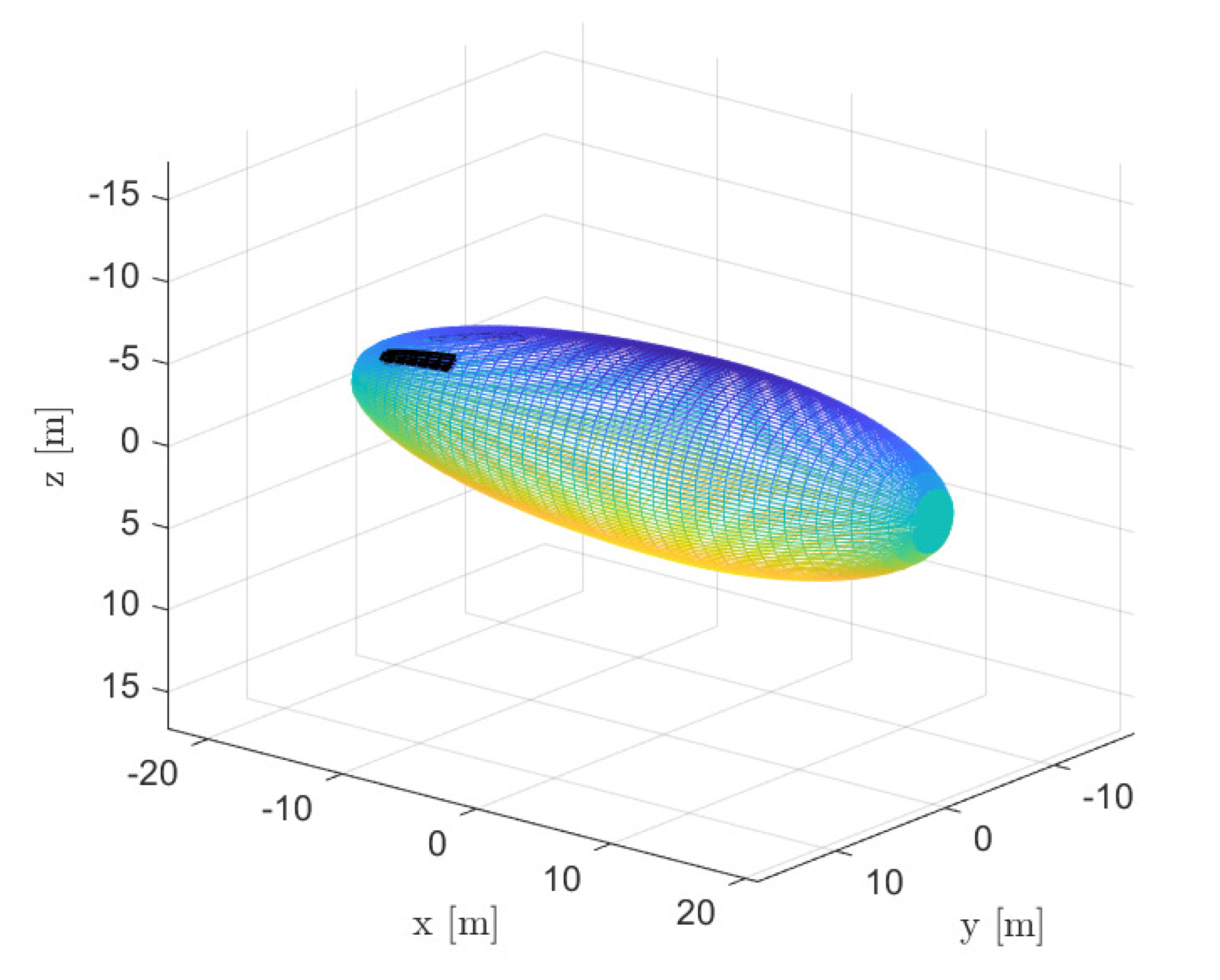
 Table 7, whereas Figure 6 shows the layout of the corresponding optimal design for the airship.
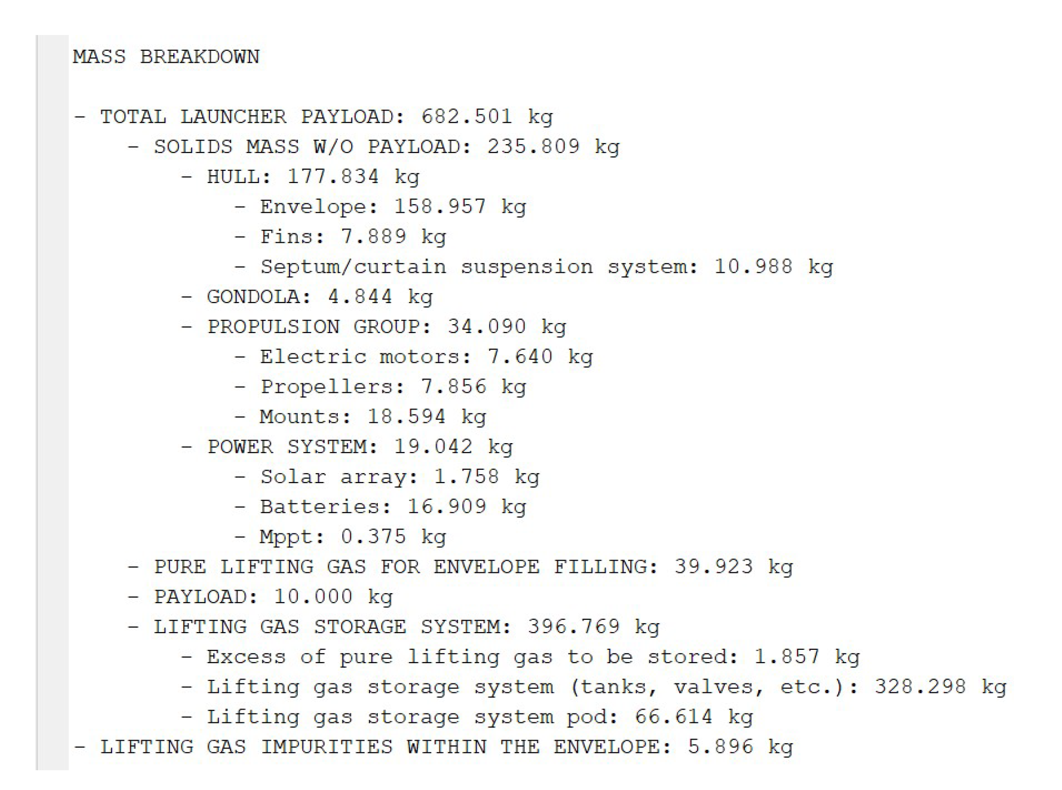
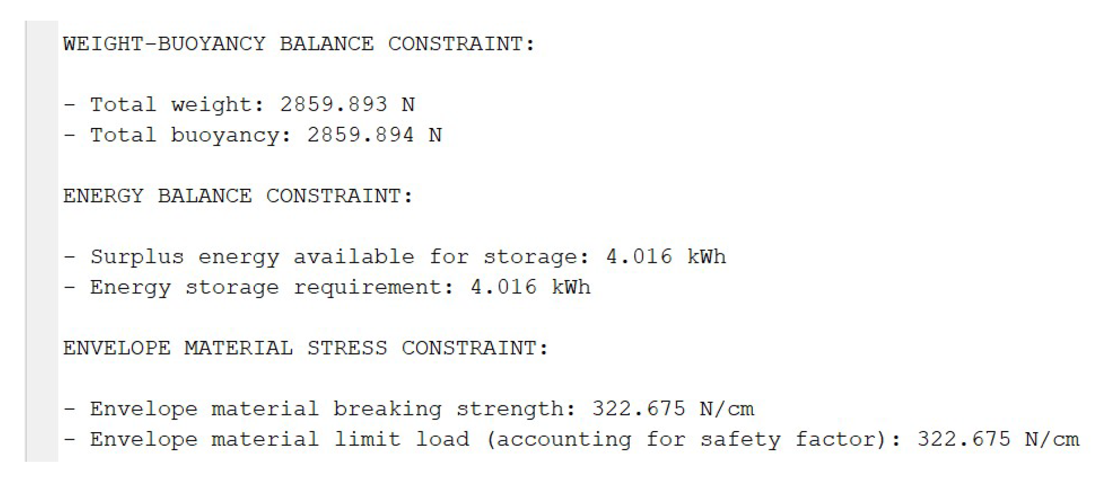
The details of the optimal solution and its components, as output by an implementation of the optimal design algorithm, are presented in Figure 7 and Figure 8, which provide, respectively, the mass breakdown and the constraints evaluation obtained from the methodology.
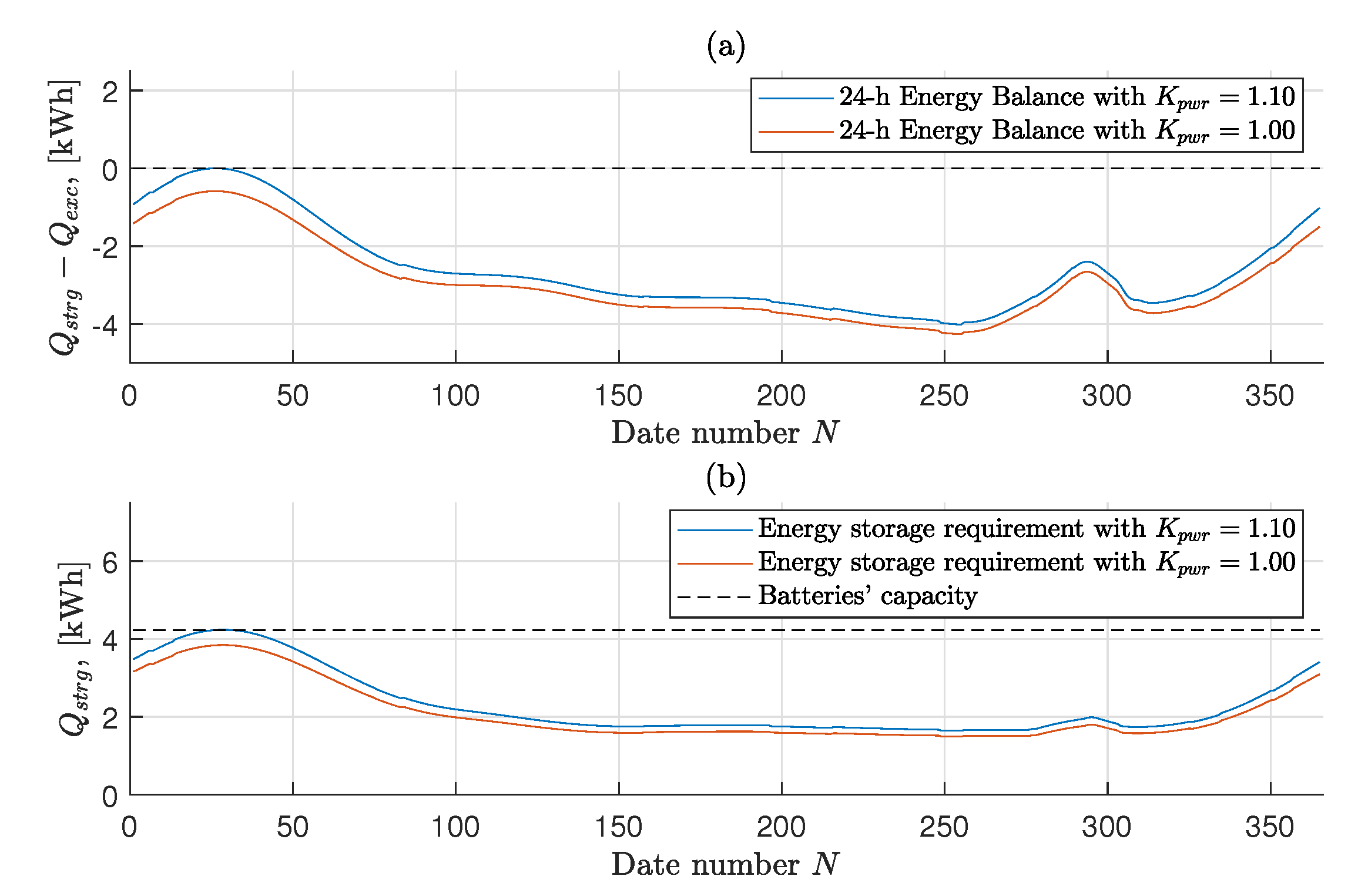
Finally, Figure 9 shows the feasibility of the obtained solution for year-round operation, reporting both the evaluation of the 24-h energy balance and the required battery capacity throughout the year. In particular, having selected January 26 as the date for the design, the 24-h energy balance is strictly satisfied on every day of the year even considering a 10% increase in power consumption assumed in the design for safety ( s p w r = 1.1 ). Concerning the energy storage requirement, instead, a maximum additional 0.19% mass of batteries is still required on 29 January. However, considering the actual power consumption predicted by the methodology ( s p w r = 1.0 ) instead of that increased with a 10% margin adopted as mentioned, the capacity of batteries is also sufficient for every day of the year, and a good margin is maintained even on 29 January.

4.2.2. Comparison of Optimal Sizing Results for Different Geographical Locations at 20 km Altitude

The main parameters output by the optimization process for the four case studies just introduced above (Section 4.2) are reported in Table 8.
The influence of the specific stratospheric environment over the different geographical locations on airship sizing is evident from Table 8. Required propulsion power increases with the third power of the wind speed, increasing the need to store energy to ensure continuous operation. This results in an increase of the energy storage system mass, as well as that of the solar array. Furthermore, power consumption is also dependent on the geometrical size of the airship. Increasing airship volume provides increased lift, required to balance the increased weight of the overall system. However, the increased size induces an increase in power required, due to the larger drag of the airship. This in turn increases the mass of the airship again. Because of this connection between airship size, lifting capacity, and power production and consumption, converging to a feasible solution with a sizing such to generate the required lift and capable of producing and storing enough energy suggests an iterative process, in which alterations in mass or power consumption can translate into large changes in airship size. This stands in support of the choice of an automatic solver in the search for a sizing solution.
The coupling of the required and available power with the environment makes the sizing dependent on both where and when it is to be flown. Hence, the extremely low wind speed in Pontianak, combined with the fact that, lying on the equator, the number of daylight hours is practically unchanged throughout the year, result in a system with a size and weight which are smaller compared to those resulting for other locations—even by an order of magnitude comparing the cases of Port-au-Prince and L’Aquila.
Airstream speed, in particular, is a main driver of the sizing. Actually, the system designed for operation above Port-au-Prince, where wind speeds are the highest at 20 km altitude, is characterized by the largest size and energy storage requirement, and consequently also by the highest total mass, as well as the highest mass of many components. Similarly, the maximum wind speed at 20 km altitude above L’Aquila is higher than above Houston, and consequently the system designed for the former location features a higher power consumption and larger size and mass.
However, where the difference in maximum wind speed are comparable, the increase in overall mass between L’Aquila and Houston is much larger compared to that between Port-au-Prince and L’Aquila. The reason, which can be understood by looking at the energy storage requirements, lies in the critical conditions that drove the design in the three cases. On the one hand, at 20 km altitude Port-au-Prince and Houston have their critical day of the year in summer, when there are more daylight hours and thus the energy storage requirement is made less stringent by the shorter time for which the solar array is not capturing power. The opposite scenario is encountered in L’Aquila, where the most critical day at 20 km altitude occurs in the middle of the winter, when less than 10 daylight hours are available, and thus the energy storage requirement is more stringent. This difference is also reflected by the required area and mass of the solar array. Despite the lower energy storage requirement, the optimal solution for operation above L’Aquila is characterized by a larger solar array than the one designed to operate above Port-au-Prince. In fact, due to the fewer daylight hours on the critical design date, in the former case the energy for night operation must be collected in a shorter time, meaning that a higher output power from the solar array, and hence a larger solar cell surface, are required.
Broadly speaking, it should be observed that for locations such as Port-au-Prince and L’Aquila, and to a lesser extent Houston, a system with a large mass is required to carry a payload which is relatively limited in both mass and power consumption. This would practically result in the unfeasibility of a missile-deployed HAPS concept in such locations, at the considered altitude and with the adopted baseline technologies. This is due to the inability of such a heavy system to fit into any small enough missile that would allow the ease of transport and handling and the fast deployment required to meet the time responsiveness goal underlying the proposed concept. By carefully analyzing the weight distribution among the various components listed in Table 8, where envelope and batteries are the major contributors to the mass of the airship (except in the Pontianak case, in which the energy storage requirement is minimal), what actually contributes most to the excessive weight of the system is not the airship itself but rather the lifting gas storage system, which due to the low gravimetric capacity of state-of-the-art tanks takes a portion around 58% of the total weight of the airship, and therefore of the missile payload.
A further consideration applies, which supports the use of an automatic approach to the sizing, considering the trade-off between length and fineness ratio to obtain the volume required for the airship in order to balance its own weight. In fact, such volume can be obtained either with a combination of increased length and fineness ratio, or, on the contrary, with a combination of reduced length and fineness ratio. A number of aspects relevant to airship design and operation are influenced by its geometry, meaning that manually selecting such combination would require taking into account several different considerations. For instance, volume and area of the airship do not vary in the same way for changing length and fineness ratio, but the more the shape deviates from the spherical one, the larger the surface area of the hull becomes. Then, the volumetric drag coefficient depends on the shape of the airship, and specifically it is a function of the fineness ratio, with an optimal value depending on the operational Reynolds number range of the airship. In addition, the stress acting on the envelope skin is influenced by the shape of the hull, both the hoop and the longitudinal stresses being influenced by the diameter and the fineness ratio. Finally, a higher length or a larger diameter may be needed to place the solar array such that it is better radiated by sunlight.
The optimization algorithm can conveniently manage all these conflicting factors and determine the optimal layout depending on the required size of the airship, the specific conditions in which it should operate, and the characteristics of the components employed (strength-to-weight ratio of the envelope material, efficiency of the solar array, etc.), resulting in different combinations of length and fineness ratio defining the geometry of the platform in different case studies.

4.3. Studying the Effect of Stationing Altitude

The purpose of this section is to show how the selection of an appropriate operational altitude can considerably influence the sizing and design of the HAA and specifically grant the potential feasibility of the missile-deployed HAPS concept, for the reasons bound to the missile payload outlined in the final remarks of Section 4.2.2. The goal of the proposed analysis is not to determine the optimal altitude at which the airship should be flown over a certain location, i.e., the stationing altitude is not considered as a further optimization parameter, but it is treated as a parameter to investigate how sensitive the design is to it.
The approach presented here is based on a model trying to predict the relative drag acting on the airship, as a function of airstream speed and air density only. Actually, Equation (35) is used here, inspired by [6],
P r e l = v w i n d 3 ρ 2 / 3
where the relative drag has been multiplied by the airstream speed v w i n d , since the required propulsive power is assumed to be the quantity to be minimized in order to effectively reduce the size and weight of the airship. For a given location, Equation (35) is used to build a three-dimensional surface representing the relative propulsive power P r e l required for station keeping as a function of both altitude and day of the year. This way, for each altitude the most critical day of the year can be identified based on this relative propulsive power only. The altitude at which the relative propulsive power on the worst day is the smallest can be assumed as the most suitable for airship operation in that geographical location.
Clearly, the stationing altitude obtained with this method will be sub-optimal due to a number of reasons. Firstly, Equation (35) provides just an estimate, which obviously cannot capture all aspects that influence the power requirement of the airship. Furthermore, as in the previous section, airstream speed and thus relative propulsive power are evaluated at a given time (midnight), which might result in an underestimation of the top value adopted for sizing. Finally, airstream speed and related propulsive power are not the only aspects relevant to the operation of the airship.
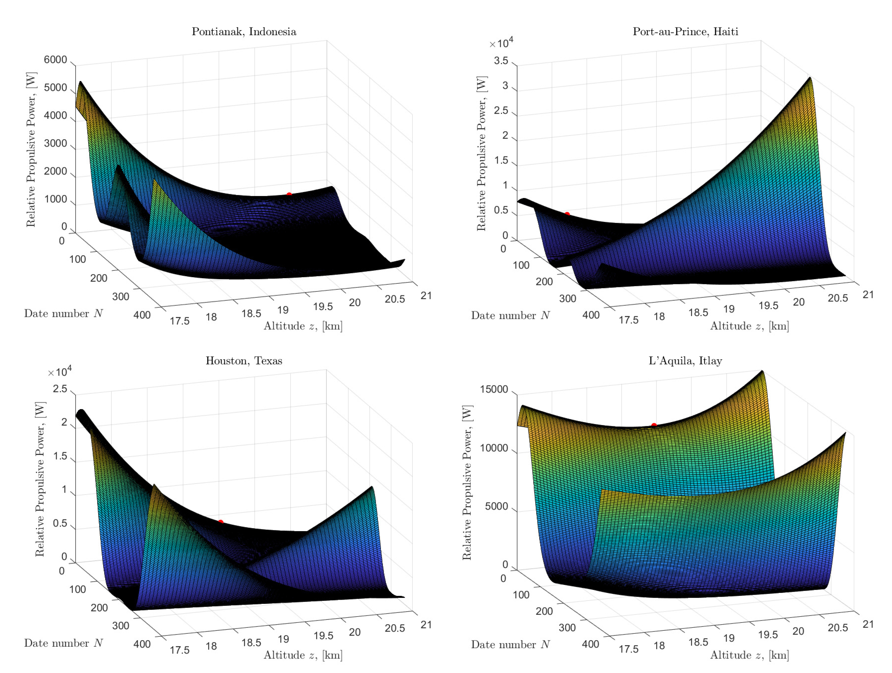
The plots in Figure 10 show the three-dimensional surfaces obtained for the four considered locations, representing the relative propulsive power required for station keeping evaluated at midnight of each day of the year, for altitudes between 17.5 km and 21 km. Pontianak and L’Aquila are characterized by a specific time of the year, namely winter, in which wind speed and thus relative propulsive power are higher compared to the rest of the year. The most advisable altitude for the operation of the airship is on the lowest point of the only ridge on the surface (marked by a red dot on the plots). Conversely, Port-au-Prince and Houston are characterized by a higher variability of the airstream speed with altitude throughout the year, resulting in two distinct ridges, one in winter, which decreases with altitude, and the other in summer, which instead increases with altitude. The most convenient altitude for year-round operation is where the two ridges are equally high (marked again by a red dot on the winter ridge only).
The stationing altitude suggested for Pontianak and L’Aquila is, respectively, 20.38 km and 19.41 km, but in both cases the slope of the ridge for altitudes around the minimum is small, meaning there is no significant difference in considering these values or a 20 km altitude as previously assumed. On the contrary, for Port-au-Prince and Houston, for which the most convenient altitudes resulting from the considered approach are 18.06 km and 19.46 km, respectively, due to the considerable slope of the two ridges, i.e., the sensitivity of required propulsive power with altitude, a significant difference between the new altitude instead of the 20 km previously assumed shall be encountered.

Re-Design for a Different Altitude, Port-au-Prince Case

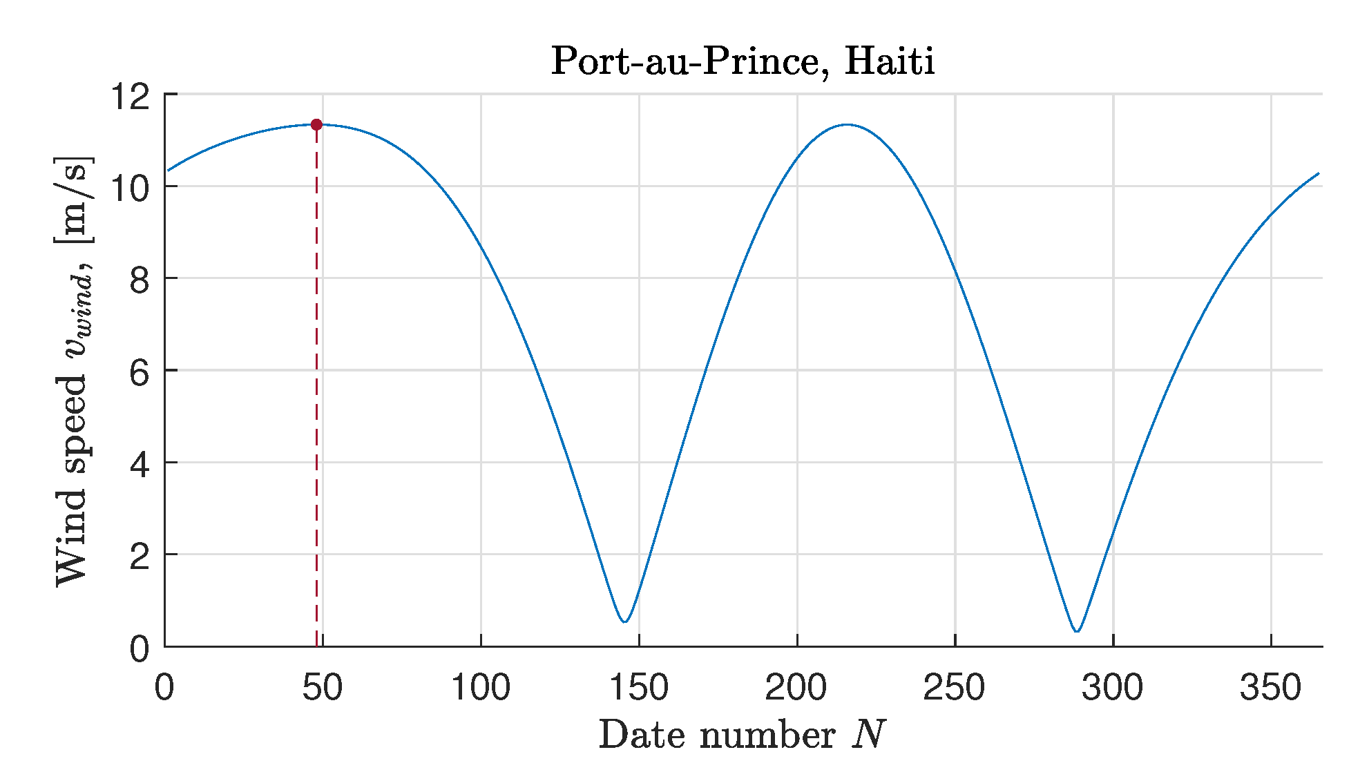
Considering the case of Port-au-Prince as an example, in order to assess the convenience of the estimated 18.06 km stationing altitude compared to the 20 km previously considered, the design of the system has been re-performed for such location, changing only the operating altitude and design day. Concerning the most critical day for the design, the date corresponding to the red dot in Figure 10, namely February 17, is selected as a first guess. The annual wind profile at the new fixed altitude of 18.06 km above Port-au-Prince is shown in Figure 11. This can be extracted from Figure 10 in correspondence to the considered altitude.
The selection of the design date is refined with the same approach previously explained (Section 4.2). With the optimal solution resulting from the design performed on 17 February, both a maximum 12.67% violation of the 24-h energy balance and a maximum 18.53% additional energy storage requirement occur on 5 August. Therefore, the design of the HAPS platform for continuous operation throughout the year at 18.06 km altitude above Port-au-Prince is repeated considering this new date, resulting in a set of mission specifications reported in Table 9.
The optimal layout resulting from the design methodology is given in Table 10 and Figure 12.
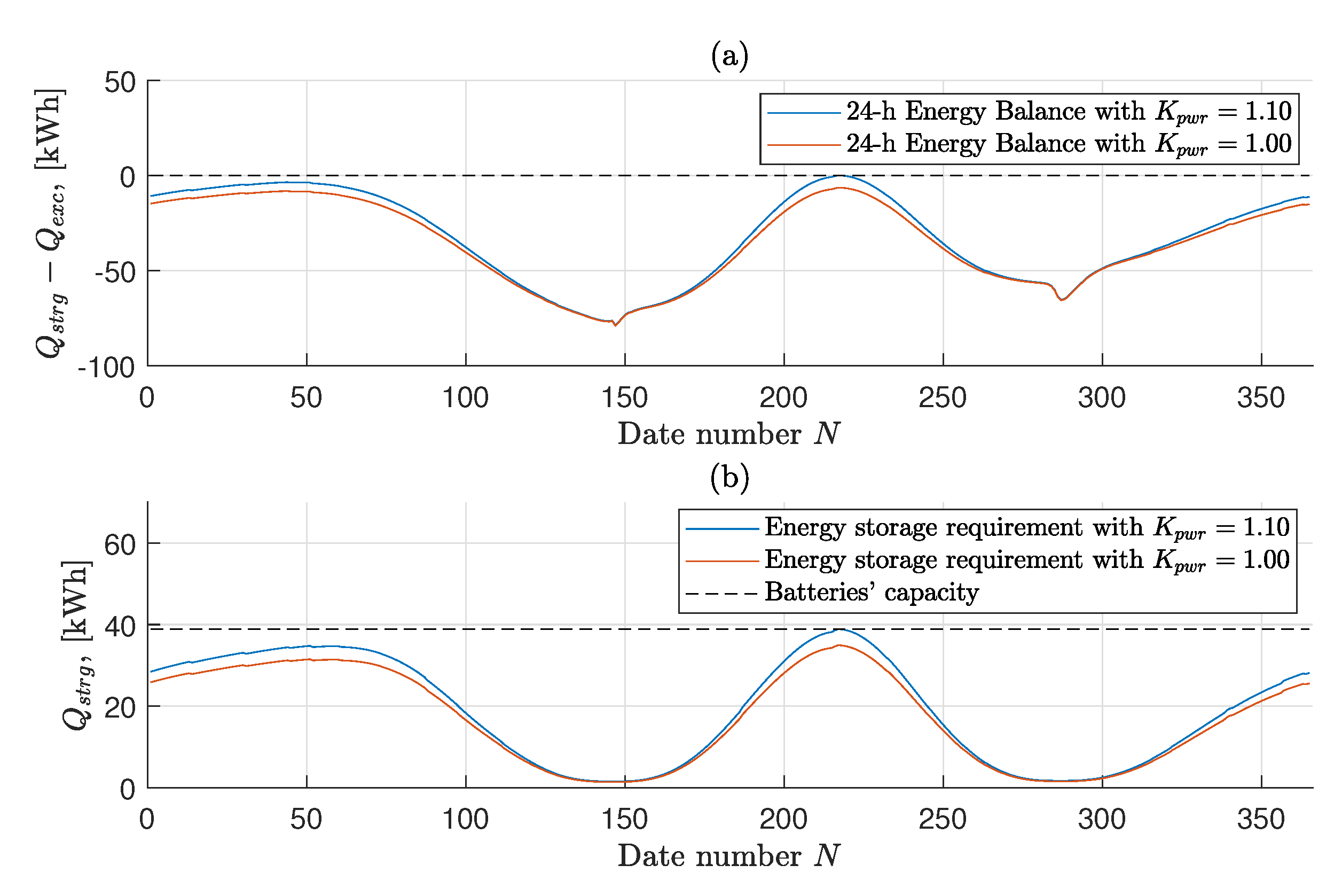
The feasibility of the designed optimal solution is assessed by means of Figure 13, where it is possible to visually check the fulfillment of the 24-h energy balance and the required energy storage throughout the year. The capacity of the batteries resulting from the design is sufficient, even considering a 10% margin over power consumption. Concerning the 24-h energy balance instead, the only violation occurs on the same day for which the design has been conducted, falling within the constraint tolerance of the optimization algorithm.
Finally, a comparison between the optimal solutions obtained for year-round operation at 20 and 18.06 km altitudes above Port-au-Prince is reported in Table 11.
The advantage of reducing the operating altitude of the HAPS platform is evident from Table 11. The significant reduction of the maximum wind speed that the airship is expected to face when it is sized for the new altitude, together with the increase in air density (that appears at the denominator in Equation (35)), and that allows a given amount of lift to be generated with a smaller volume), leads to a substantial decrease in power consumption, and therefore energy harvesting and storage requirement, as well as in the size of the airship. As a result, the mass of the batteries and all power system components are greatly reduced and similarly is the mass of all other components onboard. The final result is a dramatic 82.88% reduction in HAPS size and a 76.79% reduction in its total mass. Considered as the payload for a missile responsible for positioning the HAPS at altitude, the new values constitute a feasible solution, according to the technology and size of existing launchers.

4.4. Effects of Technology on Optimal Sizing

In this section, the potential of some technological advancements on the outcome of the optimal design phase is analyzed. In particular, understanding whether such technological advances may ensure the feasibility of the missile-launched HAPS, by reducing its overall weight, is of interest here. The case study of L’Aquila is taken into account in this section, since according to the result of the sizing previously presented, a missile deployment is hardly feasible in that case. Each change investigated in the HAPS baseline design is introduced individually, in order to ease the evaluation of its specific impact. In addition, the effect of combining first only some, and finally all changes, is investigated.
In the following, a list of the combinations of alterations to the technological settings for HAPS optimal design is presented. Firstly, potential advancements in the three main key technologies for an HAA—namely envelope material, batteries, and photovoltaic film—are taken into account. Furthermore, some alternatives concerning the safety factors used for structural sizing, as well as lifting gas properties, are explored.
1.
Case #1: envelope’s laminated material with higher strength-to-weight ratio. In particular, the relationship provided by Carichner and Nicolai for Dyneema® laminate is employed instead of that for Vectran® [12]. More in general, the resulting lower value of surface density for a given minimum required breaking strength could also refer to a material with a different load-bearing component, such as Zylon®, which is characterized by a strength-to-weight ratio very similar to that of Dyneema®.
2.
Case #2: batteries with higher gravimetric energy density. A specific energy of the batteries of q b a t = 400 Wh/kg can be considered a target within reach for a number of commercial and non-commercial available technologies, such as Li-ion with silicon nanowire anode (Amprius), Li-metal (SionPower, SolidEnergy), and Li-S (Oxis), once issues related to safety, instability, and limited cycle life are completely solved.
3.
Case #3: thin photovoltaic film with higher conversion efficiency. Based on the constantly increasing performance of best-research laboratory solar cells, η s c = 17% is considered a reasonable target for efficiency, already achieved by MiaSolé thin-film CIGS solar cells on a stainless steel substrate.
4.
Case #4: simultaneous application of Cases #1, #2, and #3.
5.
Case #5: lower safety factor over the maximum expected loads for sizing of the envelope skin material. A lower safety factor than that prescribed in FAA Airship Design Criteria for non-rigid airships may probably be used for an unmanned system, where mass and size minimization are a priority. A safety factor s σ = 3 , higher than that used in the design of the HiSentinel80, is considered.
6.
Case #6: hydrogen instead of helium as lifting gas. Safety concerns related to the flammability of hydrogen when mixed with air could take second place in an unmanned system. Hence, using hydrogen, lighter and cheaper than helium, is an interesting choice to explore.
7.
Case #7: simultaneous application of Cases #5 and #6.
8.
Case #8: simultaneous application of Cases #4 and #7.
Mission specifications are the same in all cases and are reported in Table 6. The actual feasibility for year-round operation of the solution resulting from the optimization process is then assessed as usual, and a confirmation is obtained in each case, meaning that 9 January actually remains the most critical day for the sizing of the airship and its power system, even when the considered modifications are introduced.
Table 12, Table 13, Table 14 and Table 15 summarize the values taken by the optimal design variables and the output of the optimization process when the eight alternatives listed above are considered, comparing the obtained values with those of the baseline, labeled as #0.
Concerning technological advancements, as expected, improvements in the envelope material and energy storage system characteristics have the greatest impact on the size and weight of the system. In fact, they allow a considerable lightening of the two corresponding components that contribute the most to the airship mass. On the contrary, improving the conversion efficiency (or, more in general, the output power-to-weight ratio) of the solar array is not so effective in enhancing the sizing of a stratospheric airship, due to the small fraction of total weight it takes. Altogether, the three considered technological advancements, all based on developments that are absolutely within reach, would make it possible to reduce the size and weight of the system by 76.11%, resulting in a payload for the missile weighing 1584 kg against the 6629 kg of the baseline design solution.
In addition, the proposed design improvements also have the potential to allow a significant enhancement of the system and contribute to its feasibility. In particular, lowering the envelope material sizing requirement by reducing the safety factor, while still retaining a sizable 66% margin over the maximum expected in-flight loads, is another effective method of lightening the airship envelope, leading to an overall gain in size and weight of the system. On the other hand, filling the envelope with hydrogen instead of helium would allow to more than halve the required mass of lifting gas—thanks to the lower density of hydrogen and the reduction in size following the reduced lift requirement—and consequently to reduce the weight of the system.
Jointly, the three assumed technological advancements and these two changes in the design of the platform would lead to a 85.40% reduction in airship size and a 84.70% lightening of the missile total payload, from 6629 kg to only 1014 kg. Multiple combinations of advancements could be used to achieve the same or even better results, and improvements could also be assumed for other components (gondola material, efficiencies, and power-to-weight ratios of other power-train components) or other design aspects (shape and resulting drag coefficient model, more optimistic predictions of temperature, and hence pressure variations inside the envelope). In particular, considering the dramatic influence of the lifting gas storage system on the overall weight, assuming an even only slightly better gravimetric capacity of high-pressure tanks would greatly contribute to its reduction. However, the obtained results, based on reliable and attainable assumptions only, represent the proof of the potential to obtain, by means of a fair level of improvement, a system with a size and weight small enough to enable the missile-deployed HAPS concept, even for year-round operation within a high wind area such as that at 20 km altitude in the test case of L’Aquila.

5. Conclusions

The aim of the present work was that of investigating the feasibility of the concept of a launcher-deployable high altitude airship (HAA) for a high-altitude pseudo-satellite (HAPS) mission. This mission puts the weight of the entire HAA at a premium, since it should be intended as the payload of a missile launcher. In order to perform such analysis, the limited fidelity of environmental models for the wind and solar radiation at altitude typically adopted for preliminary sizing is not sufficient. Therefore, high-fidelity modeling of the environment, and of the interaction with a specific shape of the envelope and of solar arrays, has been taken into account.
The first-principle or semi-empirical models required to obtain a sizing, starting from mission requirements, have been introduced and implemented in an optimal framework, where the loop is iterated in the search for a design solution with the minimum achievable take-off mass while simultaneously capable of verifying a set of constraints.
The sizing procedure has been validated in the case of an existing airship, showing a very good agreement with a real field test case.
The sizing methodology has been used intensively to carry out a parameter analysis in four testing scenarios, corresponding to largely different geographical locations, and hence to different atmospheric and radiation conditions. In this phase, stationing altitude has been assigned equal to all analysis conditions. The complete energy balance of the mission over a yearly time frame has been considered, accounting for changing values of radiation and wind over a one year period, as well as on a daily basis. The results have shown a significant difference in the optimal sizing in the respective geographical cases, highlighting a generally strong dependence on the choice of the coordinates of deployment on the resulting HAA weight-optimal sizing. Where generally this allows one to carry out the deployment of the airship at altitude by means of a missile, the outcome of the comparative analysis shows that there exist critical conditions (i.e., critical sets of requirements) that jeopardize the adoption of the corresponding design solutions as payloads of a missile launcher.
Concurrently, further parameter analysis has been carried out, again computing sizing solutions through the methodology introduced in this work, to ascertain whether mission specifications, such as the stationing altitude, or technological parameters, including qualities of the materials, may be tuned to bear a satisfying design solution, i.e., an optimal solution satisfying mission requirements, and to be possibly loaded on a missile to be employed for deployment. The results of this parameter analysis have shown that such a solution indeed exists, with a proper choice of the mission and technological parameters. However, the relationship between technological assumptions and environmental conditions for a specific mission strongly influences the feasibility of a missile-deployable HAA for HAPS missions.
Future development of the present work will include the analysis of further technologies in the design process, including technologies for energy storage, in particular structural batteries, as well as altogether different power-trains, such as hydrogen-based fuel cells. These may further increase the efficiency in the usage of the masses on board, thus potentially allowing for more payload to be included in the airship design.

Author Contributions

C.E.D.R. and A.R. synthesized and structured the outcomes of the research, composing the present article. G.R. contributed to the refinement of the formulation and carried out the quantitative analyses. All authors participated equally in the development of the body of the work, contributing discussions and critical comments to the methodology and results. All authors have read and agreed to the published version of the manuscript.

Funding

This research received no external funding.

Informed Consent Statement

Not applicable.

Conflicts of Interest

The authors declare no conflict of interest.

References

  1. Chu, A.; Blackmore, M.; Oholendt, R.G.; Welch, J.V.; Baird, G.; Cadogan, D.P.; Scarborough, S.E. A Novel Concept for Stratospheric Communications and Surveillance: Star Light. In Proceedings of the AIAA Baloon Systems Conference, Williamsburg, VA, USA, 21–24 May 2007. [Google Scholar] [CrossRef]
  2. Miller, S.H.; Fesen, R.; Hillenbrand, L.; Rhodes, J.; Baird, G.; Blake, G.; Booth, J.; Carlile, D.E.; Duren, R.; Edworthy, F.G.; et al. Airships: A New Horizon for Science; Technical Report; Keck Institute for Space Studies: Pasadena, CA, USA, 2014. [Google Scholar]
  3. Romeo, G.; Frulla, G.; Cestino, E. Design of a high-altitude long-endurance solar-powered unmanned air vehicle for multi-payload and operations. J. Aerosp. Eng. 2007, 221, 199–216. [Google Scholar] [CrossRef] [Green Version]
  4. Drob, D.P.; Emmert, J.T.; Crowley, G.; Picone, J.; Shepherd, G.G.; Skinner, W.; Hays, P.; Niciejewski, R.J.; Larsen, M.; She, C.Y.; et al. An empirical model of the Earth’s horizontal wind fields: HWM07. J. Geophys. Res. Space Phys. 2008, 113, A12304. [Google Scholar] [CrossRef]
  5. Gueymard, C. SMARTS2, a Simple Model of the Atmospheric Radiative Transfer of Sunshine: Algorithms and Performance Assessment; Technical Report FSEC-PF-270-95; Florida Solar Energy Center: Cocoa, FL, USA, 1995. [Google Scholar]
  6. Colozza, A. Initial Feasibility Assessment of a High Altitude Long Endurance Airship; Technical Report NASA/CR–2003-212724; Analex Corp.: Brooks Park, OH, USA, 2003. [Google Scholar]
  7. Gonzalo, J.; López, D.; Domínguez, D.; García, A.; Escapa, A. On the capabilities and limitations of high altitude pseudo-satellites. Prog. Aerosp. Sci. 2018, 98, 37–56. [Google Scholar] [CrossRef]
  8. d’Oliveira, F.A.; de Melo, F.C.L.; Devezas, T.C. High-Altitude Platforms—Present Situation and Technology Trends. J. Aerosp. Technol. Manag. 2016, 8, 249–262. [Google Scholar] [CrossRef]
  9. Everaerts, J.; Lewyckyj, N.; Fransaer, D. Pegasus: Design of a Stratospheric Long Endurance UAV System for Remote Sensing. In Proceedings of the 20th Congress of the International Society for Photogrammetry and Remote Sensing (ISPRS), Istanbul, Turkey, 12–23 July 2004; Vito, Flemish Institute for Technological Research: Mol, Belgium, 2004. [Google Scholar]
  10. Baraniello, V.R.; Persechino, G.; Borsa, R. Tools for the Conceptual Design of a Stratospheric Hybrid Platform; SAE Technical Paper; SAE: Warrendale, PA, USA, 2020. [Google Scholar] [CrossRef]
  11. Jenkins, J.E.; Samsundar, J.; Neradka, V.F. A Design Methodology for Optimal Power Generation in High Altitude Airships Using Genetic Algorithms. In Proceedings of the 3rd International Energy Conversion Engineering Conference, San Francisco, CA, USA, 15–18 August 2005. [Google Scholar] [CrossRef]
  12. Carichner, G.E.; Nicolai, L.M. Fundamentals of Aircraft and Airship Design; AIAA Education Series; American Institute of Aeronautics and Astronautics, Inc.: Reston, VA, USA, 2013. [Google Scholar]
  13. Lobner, P. HiSentinel Stratospheric Airships; Technical Report; Lyncean Group of San Diego: Point Loma, CA, USA, 2020. [Google Scholar]
  14. Lobner, P. DARPA Integrated Sensor is Structure (ISIS) Airship; Technical Report; Lyncean Group of San Diego: Point Loma, CA, USA, 2020. [Google Scholar]
  15. Lobner, P. Lockheed Martin HALE-D; Technical Report; Lyncean Group of San Diego: Point Loma, CA, USA, 2020. [Google Scholar]
  16. Wang, Q.; Chen, J.; Fu, G.; Duan, D.; Zhao, H. A methodology for optimisation design and analysis of stratosphere airship. Aeronaut. J. 2009, 113, 533–540. [Google Scholar] [CrossRef]
  17. Liang, H.; Zhu, M.; Guo, X.; Zheng, Z. Conceptual Design Optimization of High Altitude Airship in Concurrent Subspace Optimization. In Proceedings of the 50th AIAA Aerospace Sciences Meeting including the New Horizons Forum and Aerospace Exposition, Nashville, TN, USA, 9–12 January 2012. [Google Scholar] [CrossRef]
  18. Chen, Q.; Zhu, M.; Sun, K. Analysis to Effects on Conceptual Parameters of Stratospheric Airship with Specified Factors. J. Comput. 2011, 6, 1055–1062. [Google Scholar] [CrossRef] [Green Version]
  19. Yang, X.; Liu, D. Conceptual Design of Stratospheric Airships Focusing on Energy Balance. J. Aerosp. Eng. 2018, 31, 04017094. [Google Scholar] [CrossRef]
  20. Zhang, L.; Zhu, W.; Du, H.; Lv, M. Multidisciplinary design of high altitude airship based on solar energy optimization. Aerosp. Sci. Technol. 2021, 110, 106440. [Google Scholar] [CrossRef]
  21. Pant, R.; Shaik, S. Conceptual Design, Initial Sizing and Sensitivity Analyses of a High Altitude Airship using revised Volumetric Drag. In Proceedings of the 57th Israel Annual Conference on Aerospace Sciences, Tel Aviv-Haifa, Israel, 15–16 March 2017. [Google Scholar]
  22. Li, J.; Lv, M.; Sun, K. Optimum area of solar array for stratospheric solar-powered airship. J. Aerosp. Eng. 2016, 231, 2654–2665. [Google Scholar] [CrossRef]
  23. Wang, Q.B.; Chen, J.A.; Fu, G.Y.; Duan, D.P. An approach for shape optimization of stratosphere airships based on multidisciplinary design optimization. J. Zhejiang Univ.-A 2009, 10, 1609–1616. [Google Scholar] [CrossRef]
  24. Yang, X.; Liu, D. Renewable power system simulation and endurance analysis for stratospheric airships. Renew. Energy 2017, 113, 1070–1076. [Google Scholar] [CrossRef]
  25. Hoerner, S.F. Fluid-Dynamic Drag; Hoerner Fluid Dynamics: Bakersfield, CA, USA, 1965. [Google Scholar]
  26. Jones, S.P.; DeLaurier, J.D. Aerodynamic estimation techniques for aerostats and airships. J. Aircr. 1982, 20, 120–126. [Google Scholar] [CrossRef]
  27. Drob, D.P.; Emmert, J.T.; Meriwether, J.W.; Makela, J.J.; Doornbos, E.; Conde, M.; Hernandez, G.; Noto, J.; Zawdie, K.A.; McDonald, S.E.; et al. An update to the Horizontal Wind Model (HWM): The quiet time thermosphere. Earth Space Sci. 2015, 2, 301–319. [Google Scholar] [CrossRef]
  28. Riboldi, C.E.D.; Trainelli, L.; Rolando, A.; Mariani, L. Predicting the effect of electric and hybrid electric aviation on acoustic pollution. Noise Mapp. 2020, 7, 35–36. [Google Scholar] [CrossRef]
  29. Gueymard, C.A. SMARTS Code, Version 2.9.5 for Windows, User’s Manual; Technical Report; Solar Consulting Services: Colebrook, NH, USA, 2005. [Google Scholar]
  30. SMARTS: Simple Model of the Atmospheric Radiative Transfer of Sunshine. Available online: www.nrel.gov/grid/solar-resource/smarts.html (accessed on 1 December 2021).
  31. Schopferer, S.; Liersch, C.; Brizon, M.; Froese, S. Evaluating the Energy Balance of High Altitude Platforms at Early Design Stages. In Proceedings of the 2016 International Conference on Unmanned Aircraft Systems (ICUAS), Arlington, VA, USA, 7–10 June 2016; pp. 170–177. [Google Scholar] [CrossRef]
  32. Bücher, K. Site dependence of the energy collection of PV modules. Sol. Energy Mater. Sol. Cells 1997, 47, 85–94. [Google Scholar] [CrossRef]
  33. Micheli, L.; Caballero, J.A.; Fernandez, E.F.; Smestad, G.P.; Nofuentes, G.; Mallick, T.K.; Almonacid, F. Correlating Photovoltaic Soiling Losses to Waveband and Single-Value Transmittance Measurements. Energy 2019, 180, 376–386. [Google Scholar] [CrossRef] [Green Version]
  34. Brizon, M. Solar Energy Generation Model for High Altitude Long Endurance Platforms; Technical Report; KTH—Royal Institute of Technology: Stockholm, Sweden, 2015. [Google Scholar]
  35. Fesharaki, V.J.; Dehghani, M.; Fesharaki, J.J.; Tavasoli, H. The Effect of Temperature on Photovoltaic Cell Efficiency. In Proceedings of the 1st International Conference on Emerging Trends in Energy Conservation (ETEC), Tehran, Iran, 20–21 November 2011. [Google Scholar]
  36. How HOMER Calculates the PV Cell Temperature. Available online: https://www.homerenergy.com/products/pro/docs/latest/how_homer_calculates_the_pv_cell_temperature.html (accessed on 1 December 2021).
  37. Keidel, B. Auslegung und Simulation von Hochfliegenden, Dauerhaft Stationierbaren Solardrohnen. Ph.D. Thesis, Lehrstuhl für Flugmechanik und Flugregelung Technische Universität München, Munich, Germany, 2000. [Google Scholar]
  38. Gawale, A.; Raina, A.; Pant, R.; Jahagirdar, Y. Design, Fabrication and Operation of Remotely Controlled Airships in India. In Proceedings of the 26th Congress of International Council of the Aeronautical Sciences (ICAS), Anchorage, AK, USA, 14–19 September 2008. [Google Scholar] [CrossRef]
  39. Khoury, G.A. Airship Technology; Cambridge Aerospace Series; Cambridge University Press: Cambridge, UK, 2012. [Google Scholar]
  40. Wu, J.; Fang, X.; Wang, Z.; Hou, Z.; Ma, Z.; Zhang, H.; Dai, Q.; Xu, Y. Thermal modeling of stratospheric airships. Prog. Aerosp. Sci. 2015, 75, 26–37. [Google Scholar] [CrossRef]
  41. Zheng, W.; Zhou, Q.; Li, Z.; Zhang, X.; Liu, Y.; Li, M. Performance analysis of a novel stratospheric airship concept based on gas-liquid phase change. Appl. Therm. Eng. 2019, 159, 113748. [Google Scholar] [CrossRef]
  42. Liu, Q.; Yang, Y.; Cui, Y.; Cai, J. Thermal performance of stratospheric airship with photovoltaic array. Adv. Space Res. 2017, 59, 1486–1501. [Google Scholar] [CrossRef]
  43. Shi, H.; Geng, S.; Qian, X. Thermodynamics analysis of a stratospheric airship with hovering capability. Appl. Therm. Eng. 2019, 146, 600–607. [Google Scholar] [CrossRef]
  44. Dai, Q.; Fang, X.; Li, X.; Tian, L. Performance simulation of high altitude scientific balloons. Adv. Space Res. 2012, 49, 1045–1052. [Google Scholar] [CrossRef]
  45. Zhang, T.; Geng, S.; Mu, X.; Chen, J.; Wang, J.; Wu, Z. Thermal Characteristics of a Stratospheric Airship with Natural Convection and External Forced Convection. Int. J. Aerosp. Eng. 2019, 2019, 4368046. [Google Scholar] [CrossRef] [Green Version]
  46. Smith, S.; Fortenberry, M.; Lee, M.; Judy, R. HiSentinel80: Flight of a High Altitude Airship. In Proceedings of the 11th AIAA Aviation Technology, Integration, and Operations (ATIO) Conference, Virginia Beach, VA, USA, 20–22 September 2011. [Google Scholar] [CrossRef]
  47. ISISPACE S-Band Transceiver. Available online: www.satcatalog.com/component/s-band-transceiver/ (accessed on 1 December 2021).
  48. Riboldi, C.E.D.; Gualdoni, F. An integrated approach to the preliminary weight sizing of small electric aircraft. Aerosp. Sci. Technol. 2016, 58, 134–149. [Google Scholar] [CrossRef]
  49. Riboldi, C.E.D. An optimal approach to the preliminary design of small hybrid-electric aircraft. Aerosp. Sci. Technol. 2018, 81, 14–31. [Google Scholar] [CrossRef]
  50. Noth, A. Design of Solar Powered Airplanes for Continuous Flight. Ph.D. Thesis, ETH Zürich, Zürich, Switzerland, 2008. [Google Scholar] [CrossRef]
  51. Riboldi, C.E.D. Energy-optimal off-design power management of hybrid-electric aircraft. Aerosp. Sci. Technol. 2019, 95, 105507. [Google Scholar] [CrossRef]
  52. Riboldi, C.E.D.; Trainelli, L.; Biondani, F. Structural batteries in aviation: A preliminary sizing methodology. J. Aerosp. Eng. 2020, 3, 040200311–040200315. [Google Scholar] [CrossRef]
  53. Barral, K.; Barthélémy, H. Hydrogen High Pressure Tanks Storages: Overview and New Trends Due to H2 Energy Specifications and Constraints; Technical Report INIS-FR–6812; IAEA: Vienna, Austria, 2006. [Google Scholar]
  54. Rivard, E.; Trudeau, M.; Zaghib, K. Hydrogen Storage for Mobility: A Review. Materials 2019, 12, 1973. [Google Scholar] [CrossRef] [Green Version]
  55. Smith, I.S. HiSentinel & Stratospheric Airship Design Sensitivity. In Proceedings of the Keck Institute for Space Studies (KISS) Workshop, Pasadena, CA, USA, 30 April–3 May 2013. [Google Scholar]
Figure 1. Modeling approach for the geometry of solar cells. (a) 3-D view. (b) y-z plane view. (c) x-z plane view.
Aerospace 09 00210 g001
Figure 2. Workflow of the sizing loop and optimization logic.
Aerospace 09 00210 g002
Figure 3. HiSentinel80 airframe configuration [46].
Aerospace 09 00210 g003
Figure 4. HiSentinel80 modeled geometry, considered for validation.
Aerospace 09 00210 g004
Figure 5. Airstream speed over the year at a 20 km altitude above Pontianak, Indonesia (0°1 14 S, 109°20 29 E). Values measured at midnight.
Aerospace 09 00210 g005
Figure 6. HAPS optimal layout for operation at 20 km altitude above Pontianak, Indonesia.
Aerospace 09 00210 g006
Figure 7. Mass breakdown of the HAPS optimal design for operation at 20 km altitude above Pontianak, Indonesia.
Aerospace 09 00210 g007
Figure 8. Constraints check for HAPS optimal design for operation at 20 km altitude above Pontianak, Indonesia.
Aerospace 09 00210 g008
Figure 9. Energy balance evaluation (a) and energy storage requirement (b) for operation throughout the year at 20 km altitude above Pontianak, Indonesia.
Aerospace 09 00210 g009
Figure 10. Three-dimensional surface representing the relative propulsive power required for station keeping on each day of the year (at midnight), at altitudes between 17.5 km and 21 km. (Top row): (left), Pontianak, (right), Port-au-Prince. (Bottom row): (left), Houston, (right), L’Aquila.
Aerospace 09 00210 g010
Figure 11. Yearly variability in airstream speed (evaluated at midnight of each day) at 18.059 km altitude above Port-au-Prince, Haiti (18°34 31 N, 72°17 41 W).
Aerospace 09 00210 g011
Figure 12. Optimal layout for operation at 18.06 km altitude above Port-au-Prince, Haiti.
Aerospace 09 00210 g012
Figure 13. Energy balance evaluation (a) and energy storage requirement (b) for operation throughout the year at 18.06 km altitude above Port-au-Prince, Haiti.
Aerospace 09 00210 g013
Table 1. Fixed parameters for a sizing loop and assumed values for computations in Section 4.2.
ParameterValueUnitDescription
k l g 0.98-Lifting gas purity.
s N C 1.5-Pressure differential safety factor for nose-caving.
Δ T c o l d 0[K]Super-cold temperature difference.
Δ T h o t 50[K]Super-hot temperature difference.
k 1 2.1 × 10 5 [1/m]Sensitivity of ρ e n v to stress.
k 2 0.14[kg/m2] ρ e n v constant in stress dependency.
s e n v 1.2-Factor for envelope mass increase.
σ e n v 900[N/cm]Tensile strength (tenacity) of the envelope material.
s σ 4-Breaking strength safety factor.
R f a 0.0121[m 1 ]Ratio of fin area to airship volume.
k f i n 2.0-Factor for fins mass increase.
k c u r t 1.06-Factor for curtain suspension system mass increase.
η p 0.80-Propeller efficiency.
η m 0.90-Electric motor efficiency.
η g 0.97-Gear transmission efficiency.
d m -[kg/W]Electric motor mass-to-power ratio (regression assumed with c m =  0).
w p 5 × 10 4 [kg/W]Propeller mass-to-power ratio.
w m 1.2-Engine mounts to propulsion group mass ratio.
η s c 0.13-Solar array conversion efficiency.
η p a c k 0.90-Solar array adjoining cells packing efficiency.
ρ s c 0.150[kg/m2]Solar array area density.
w s c 1.3-Multiplicative factor for solar array mass increase.
η M P P T 0.97-MPPT efficiency.
w M P P T 1/2368[kg/W]MPPT mass to maximum power ratio.
η c h 0.96-Energy storage system charge efficiency.
η d s c h 0.96-Energy storage system discharge efficiency.
η d o d 0.95-Energy storage system Depth-of-Discharge.
q b a t 250[W h/kg]Energy storage system specific energy.
p c h NaN[W/kg]Energy stor. syst. specific charge power (computed from q b a t here).
p d s c h NaN[W/kg]Energy stor. syst. specific discharge power (computed from q b a t here).
s p w r 1.1-Power requirement safety factor.
η t r 0.98-Transmission efficiency in/out the energy storage system.
η s w 0.90-Power switch/step efficiency in/out the energy storage system.
w g o n 0.15-Gondola to payload mass ratio.
s g o n 1.2-Gondola mass safety factor.
K t a n k 1 18-Inverse of lifting gas storage system specific capacity.
s t a n k 1.1-Tank mass safety factor.
Table 2. Parameters for the sizing tool validation on the HiSentinel80.
ParameterValueUnit
z19.812[km]
Δ z 0[km]
ϕ 36.9142[°]
λ 111.4600 [°]
Date21 December-
M p l 39.1[kg]
P p l 50[W]
v max 13.38[m/s]
Table 3. Parameters assigned specifically for the validation on the HiSentinel80.
ParameterValueUnitComment
Δ P 150[Pa]for stress computation, assigned, not computed
Δ T c o l d 15 [K]wrt. temperature at altitude
Δ T h o t 70[K]wrt. temperature at altitude
q b a t 200[Wh/kg]
ρ s c 0.120[kg/m2]
η s c 0.08-
Table 4. HiSentinel80 assumed design parameters.
ParameterValueUnit
L60.65[m]
F R 4.374-
a 1 19.05[m]
a 2 26.94[m]
x l e 5.50[m]
x t e 10.00[m]
Δ y 1.67[m]
Table 5. Comparison between HiSentinel80 and methodology predictions.
ParameterHiSentinel80PredictionUnitError
V e n v 6846.026846.68[m3]0.01%
M-627.43[kg]-
M s o l i d 484.44480.88[kg] 0.73 %
M l g -107.45[kg]-
M H e 96.1693.62[kg] 2.64 %
Table 6. Mission design specifications for operations in the considered case studies.
ParameterPontianakPort-au-PrinceHoustonL’AquilaUnit
z20202020[km]
ϕ −0.020618.575429.749942.3540[°]
λ 109.3414−72.2947−95.358413.3920[°]
Date26 January5 August3 August19 January-
M p l 10101010[kg]
P p l 100100100100[W]
v max 30303030[m/s]
Table 7. Design variables defining the HAPS optimal layout for operation at 20 km altitude above Pontianak, Indonesia.
ParameterValueUnit
L48.84[m]
F R 3.667-
x l e 34.09[m]
x t e 40.04[m]
θ i n 1.331[rad]
θ o u t 1.697[rad]
Table 8. Comparison between HAPS optimal designs for operation at 20 km altitude above the four considered locations.
Param.UnitPontianakPort-au-PrinceHoustonL’Aquila
L[m]43.84128.5368.92117.42
F R -3.6675.1854.4225.158
x l e [m]34.092.002.0038.37
x t e [m]40.0488.2455.55104.59
θ i n [rad]1.3310.0002.1212.070
θ o u t [rad]1.6970.4622.4432.876
V e n v [m3]3280.04341,365.9708765.70731,858.069
A e n v [m2]1332.8737991.3022708.5746703.987
A s c [m2]9.014435.005118.360544.908
σ b r k [N/cm]322.675668.870420.618614.189
ρ e n v [kg/m2]0.0990.1560.1160.147
Q[kWh]4.016213.15926.544148.232
M[kg]682.5018607.2961823.9406628.923
M a i r s h i p [kg]291.6283677.840779.3572832.494
M t a n k [kg]396.7695003.8121060.3393853.694
M s o l i d [kg]235.8093090.002646.9102377.471
M e n v [kg]158.9571499.369375.4101185.444
M s c [kg]1.75884.82623.080106.257
M b a t [kg]16.909897.510111.764624.135
M p r o p [kg]34.090155.06160.377132.036
M g o n [kg]4.844163.35221.917114.144
M l g [kg]45.819577.838122.448445.023
Table 9. HAPS mission design specifications for operation at 18.06 km altitude above Port-au-Prince, Haiti.
ParameterValueUnit
z18.06[km]
ϕ 18.5754[°]
λ 72.2947 [°]
Date5 August-
M p l 10[kg]
P p l 100[W]
v max 30[m/s]
Table 10. Design variables defining the optimal sizing for operation at 18.06 km altitude above Port-au-Prince, Haiti.
ParameterValueUnit
L67.71[m]
F R 4.791-
x l e 2.00[m]
x t e 40.98[m]
θ i n 1.703[rad]
θ o u t 2.184[rad]
Table 11. Comparison between HAPS optimal designs for operation at 20 and 18.06 km altitudes above Port-au-Prince, Haiti.
ParameterUnit20 km18.059 kmReduction
L[m]128.5367.71-
F R -5.1854.791-
x l e [m]2.002.00-
x t e [m]88.2440.98-
θ i n [rad]0.0001.703-
θ o u t [rad]0.4622.184-
V e n v [m3]41,365.9707083.912 82.88 %
A e n v [m2]7991.3022406.371 69.89 %
A s c [m2]435.005117.567 72.98 %
σ b r k [N/cm]668.870517.170 22.68 %
ρ e n v [kg/m2]0.1560.131 16.03 %
Q[kWh]213.15936.938 82.67 %
M[kg]8607.2961998.161 76.79 %
M a i r s h i p [kg]3677.840853.801 76.79 %
M t a n k [kg]5003.8121161.621 76.79 %
M s o l i d [kg]3090.002709.657 77.03 %
M e n v [kg]1499.369379.407 74.70 %
M s c [kg]84.82622.926 72.97 %
M b a t [kg]897.510155.529 82.67 %
M p r o p [kg]155.06167.701 56.34 %
M g o n [kg]163.35229.795 81.76 %
M l g [kg]577.838134.144 76.79 %
Table 12. Effect of technological advancements and design improvements on optimal design for operation at 20 km altitude above L’Aquila, Italy (Part 1). For each case, the first column gives the absolute value of the parameter, while the second column gives the percent reduction compared to the baseline #0.
Param.Unit#0#1#2
L[m]117.4294.37-92.30-
F R -5.1585.334-4.870-
x l e [m]38.3730.31-29.52-
x t e [m]104.5984.71-81.81-
θ i n [rad]2.0702.063-2.046-
θ o u t [rad]2.8762.882-2.899-
V e n v [m3]31,858.0715,466.27 51.45 %17,355.40 45.52 %
A e n v [m2]6703.994183.52 37.60 %4394.96 34.44 %
A s c [m2]544.91352.23 35.36 %380.22 30.22 %
σ b r k [N/cm]614.19477.44 22.27 %511.38 16.74 %
ρ e n v [kg/m2]0.1470.088 40.14 %0.130 11.56 %
Q[kWh]148.2395.81 35.37 %103.37 30.26 %
M[kg]6628.923218.17 51.45 %3611.26 45.52 %
M a i r s h i p [kg]2832.491375.10 51.45 %1543.06 45.52 %
M t a n k [kg]3853.691870.87 51.45 %2099.39 45.52 %
M s o l i d [kg]2377.471149.06 51.67 %1290.63 45.71 %
M e n v [kg]1185.44443.67 62.57 %687.92 41.97 %
M s c [kg]106.2668.68 35.36 %74.14 30.22 %
M b a t [kg]624.13403.40 35.37 %272.03 56.42 %
M p r o p [kg]132.0484.24 36.20 %91.14 30.97 %
M g o n [kg]114.1474.41 34.80 %50.77 55.53 %
M l g [kg]445.02216.05 51.45 %242.44 45.52 %
Table 13. Effect of technological advancements and design improvements on optimal design for operation at 20 km altitude above L’Aquila, Italy (Part 2). For each case, the first column gives the absolute value of the parameter, while the second column gives the percent reduction compared to the baseline #0.
Param.Unit#0#3#4
L[m]117.42120.71-68.29-
F R -5.1585.510-4.680-
x l e [m]38.3733.88-24.37-
x t e [m]104.5975.86-52.73-
θ i n [rad]2.0702.068-1.959-
θ o u t [rad]2.8762.947-2.855-
V e n v [m3]31,858.0730,330.85 4.79 %7612.13 76.11 %
A e n v [m2]6703.996619.82 1.26 %2507.02 62.60 %
A s c [m2]544.91396.34 27.27 %175.07 67.87 %
σ b r k [N/cm]614.19591.09 3.76 %393.81 35.88 %
ρ e n v [kg/m2]0.1470.144 2.04 %0.078 46.94 %
Q[kWh]148.23143.41 3.25 %63.52 57.15 %
M[kg]6628.926311.14 4.79 %1583.91 76.11 %
M a i r s h i p [kg]2832.492696.71 4.79 %676.79 76.11 %
M t a n k [kg]3853.693668.95 4.79 %920.80 76.11 %
M s o l i d [kg]2377.472263.02 4.81 %560.46 76.43 %
M e n v [kg]1185.441140.36 3.80 %235.19 80.16 %
M s c [kg]106.2677.29 27.27 %34.14 67.87 %
M b a t [kg]624.13603.83 3.25 %167.15 73.22 %
M p r o p [kg]132.04127.64 3.33 %54.81 58.49 %
M g o n [kg]114.14110.49 3.20 %31.89 72.10 %
M l g [kg]445.02423.69 4.79 %106.33 76.11 %
Table 14. Effect of technological advancements and design improvements on optimal design for operation at 20 km altitude above L’Aquila, Italy (Part 3). For each case, the first column gives the absolute value of the parameter, while the second column gives the percent reduction compared to the baseline #0.
Param.Unit#0#5#6
L[m]117.42100.05-109.22-
F R -5.1585.020-5.478-
x l e [m]38.3732.23-27.10-
x t e [m]104.5988.99-81.72-
θ i n [rad]2.0702.056-1.309-
θ o u t [rad]2.8762.889-2.197-
V e n v [m3]31,858.0720,814.5234.66%22,734.6928.64%
A e n v [m2]6703.995006.3325.32%5452.5518.67%
A s c [m2]544.91422.7522.42%461.3915.33%
σ b r k [N/cm]614.19403.4034.32%538.2612.36%
ρ e n v [kg/m2]0.1470.11323.13%0.1358.16%
Q[kWh]148.23114.9622.44%120.5818.65%
M[kg]6628.924331.0234.66%4958.5125.20%
M a i r s h i p [kg]2832.491850.6134.66%2021.3328.64%
M t a n k [kg]3853.692517.8234.66%2978.0422.72%
M s o l i d [kg]2377.471549.8634.81%1830.8222.99%
M e n v [kg]1185.44676.8642.90%882.4025.56%
M s c [kg]106.2682.4422.42%89.9715.33%
M b a t [kg]624.13484.0622.44%507.7218.65%
M p r o p [kg]132.04101.7122.97%106.8319.09%
M g o n [kg]114.1488.9322.09%93.1918.36%
M l g [kg]445.02290.7634.66%180.5259.44%
Table 15. Effect of technological advancements and design improvements on optimal design for operation at 20 km altitude above L’Aquila, Italy (Part 4). For each case, the first column gives the absolute value of the parameter, while the second column gives the percent reduction compared to the baseline #0.
Param.Unit#0#7#8
L[m]117.4290.54-60.72-
F R -5.1585.001-5.020-
x l e [m]38.3728.92-20.96-
x t e [m]104.5980.60-53.31-
θ i n [rad]2.0702.050-2.107-
θ o u t [rad]2.8762.895-2.844-
V e n v [m3]31,858.0715,539.8751.22%4649.9185.40%
A e n v [m2]6703.994115.3838.61%1843.2672.50%
A s c [m2]544.91354.9334.86%129.7976.18%
σ b r k [N/cm]614.19366.5940.31%244.9060.13%
ρ e n v [kg/m2]0.1470.10727.21%0.06059.18%
Q[kWh]148.2396.5134.89%47.1668.19%
M[kg]6628.923389.3048.87%1014.1684.70%
M a i r s h i p [kg]2832.491381.6551.22%413.4285.40%
M t a n k [kg]3853.692035.5847.18%609.1084.19%
M s o l i d [kg]2377.471248.2647.50%366.5084.58%
M e n v [kg]1185.44526.4955.59%132.7488.80%
M s c [kg]106.2669.2134.86%25.3176.18%
M b a t [kg]624.13406.3434.89%124.1080.12%
M p r o p [kg]132.0484.8835.71%39.8969.79%
M g o n [kg]114.1474.9434.34%24.1478.85%
M l g [kg]445.02123.3972.27%36.9291.70%
Publisher’s Note: MDPI stays neutral with regard to jurisdictional claims in published maps and institutional affiliations.

