
Effect of Progressive Integration of On-Board Systems Design Discipline in an MDA Framework for Aircraft Design with Different Level of Systems Electrification


Abstract
:1. Introduction
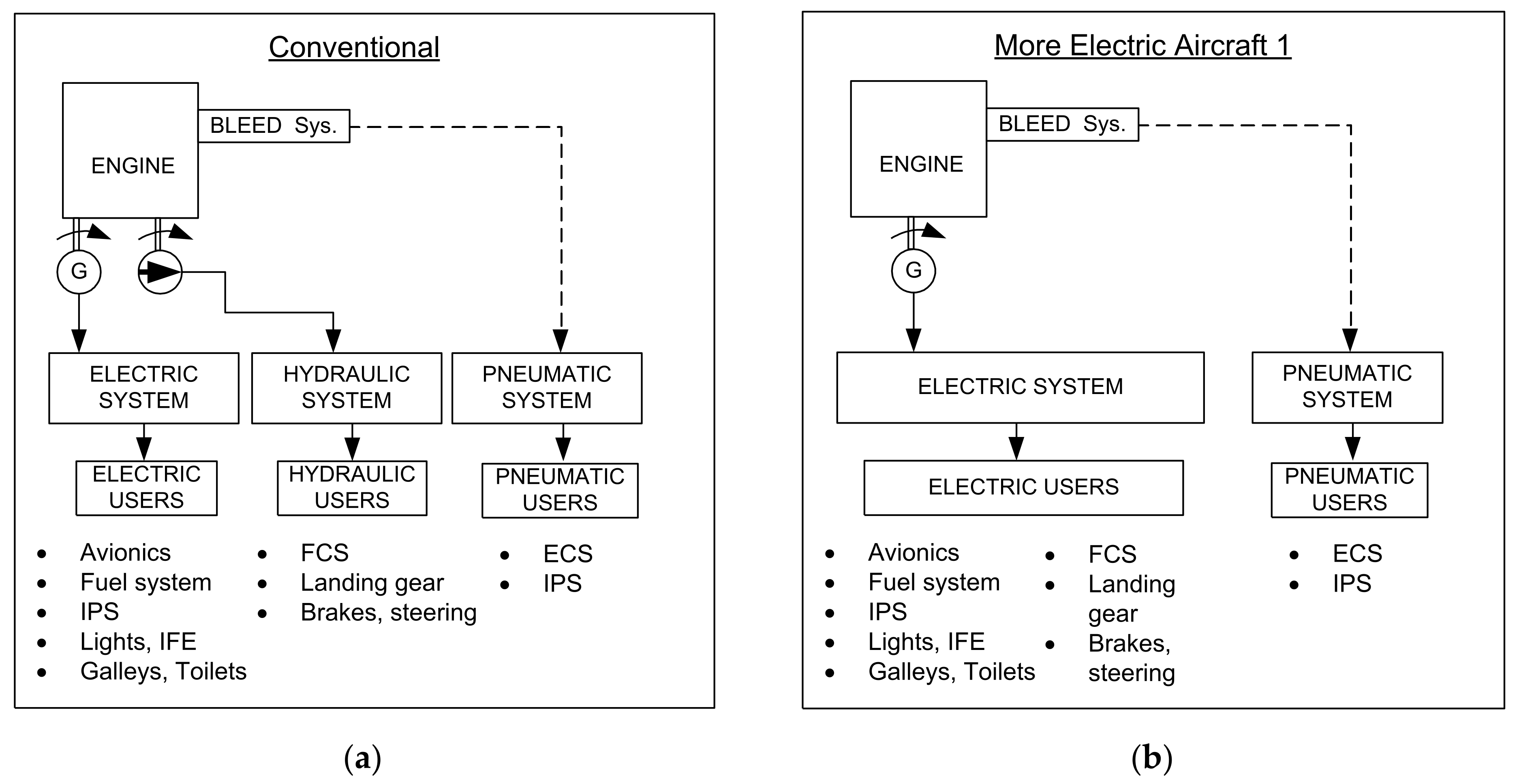
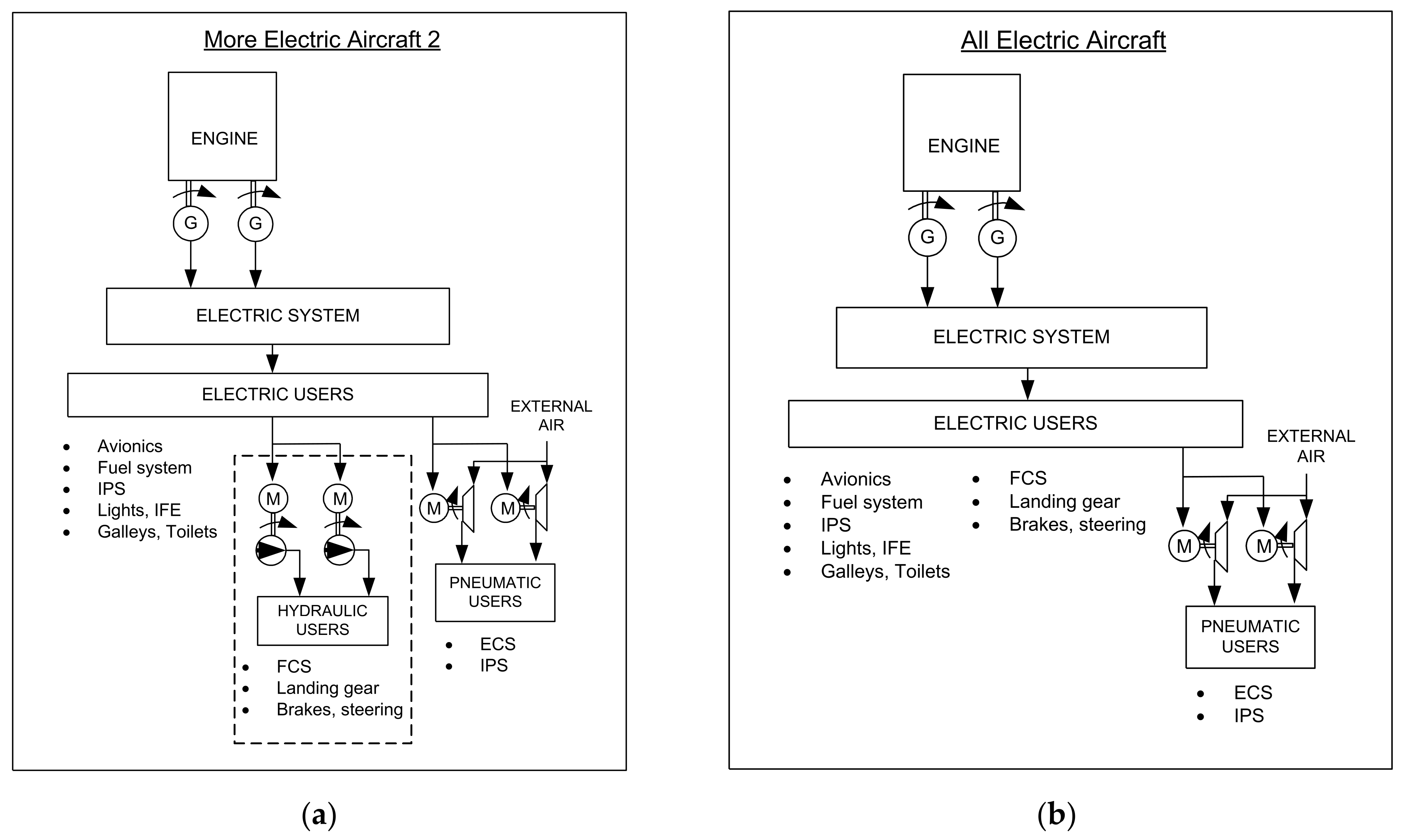
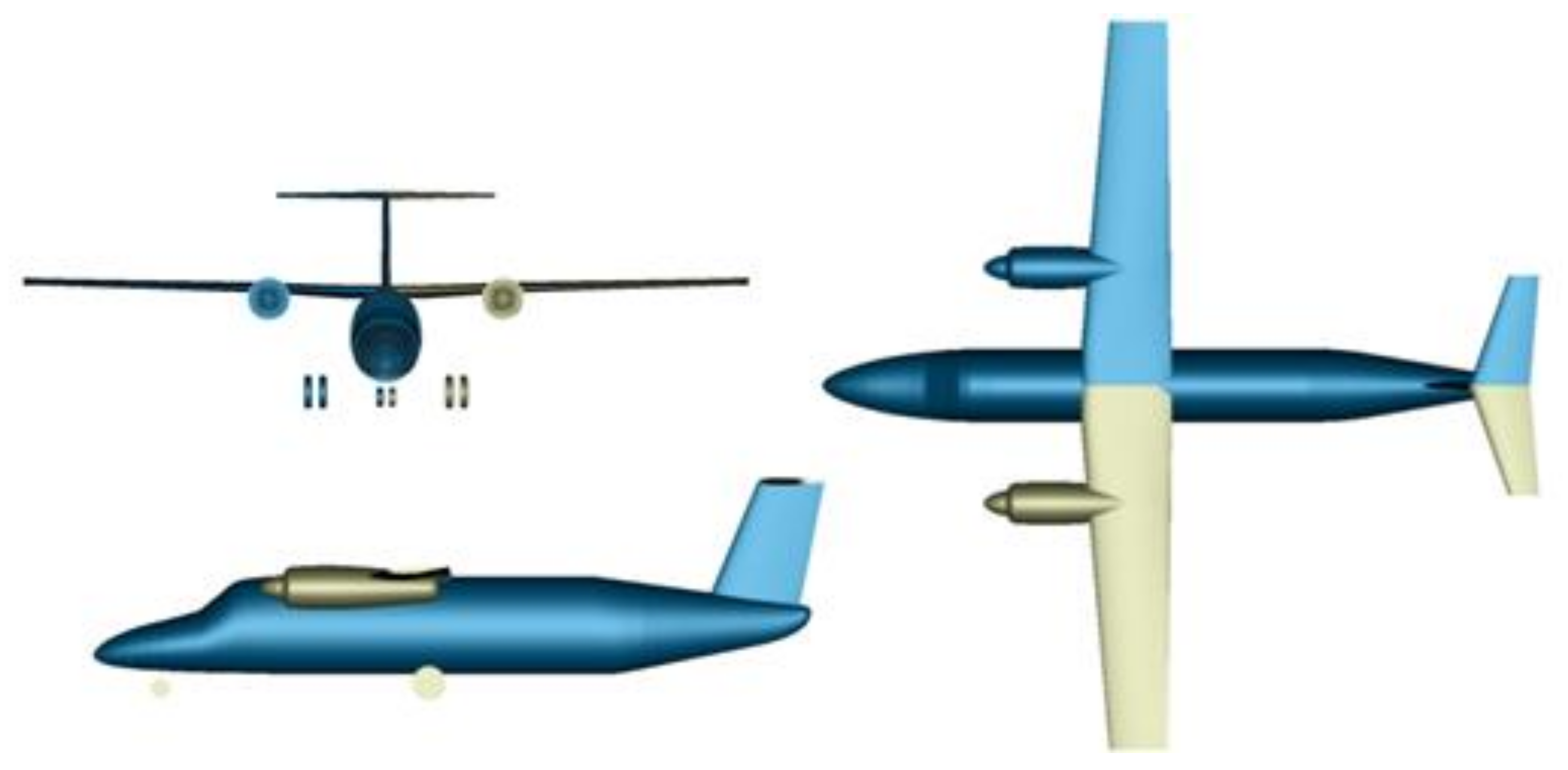
2. Reference Aircraft and OBS Architectures
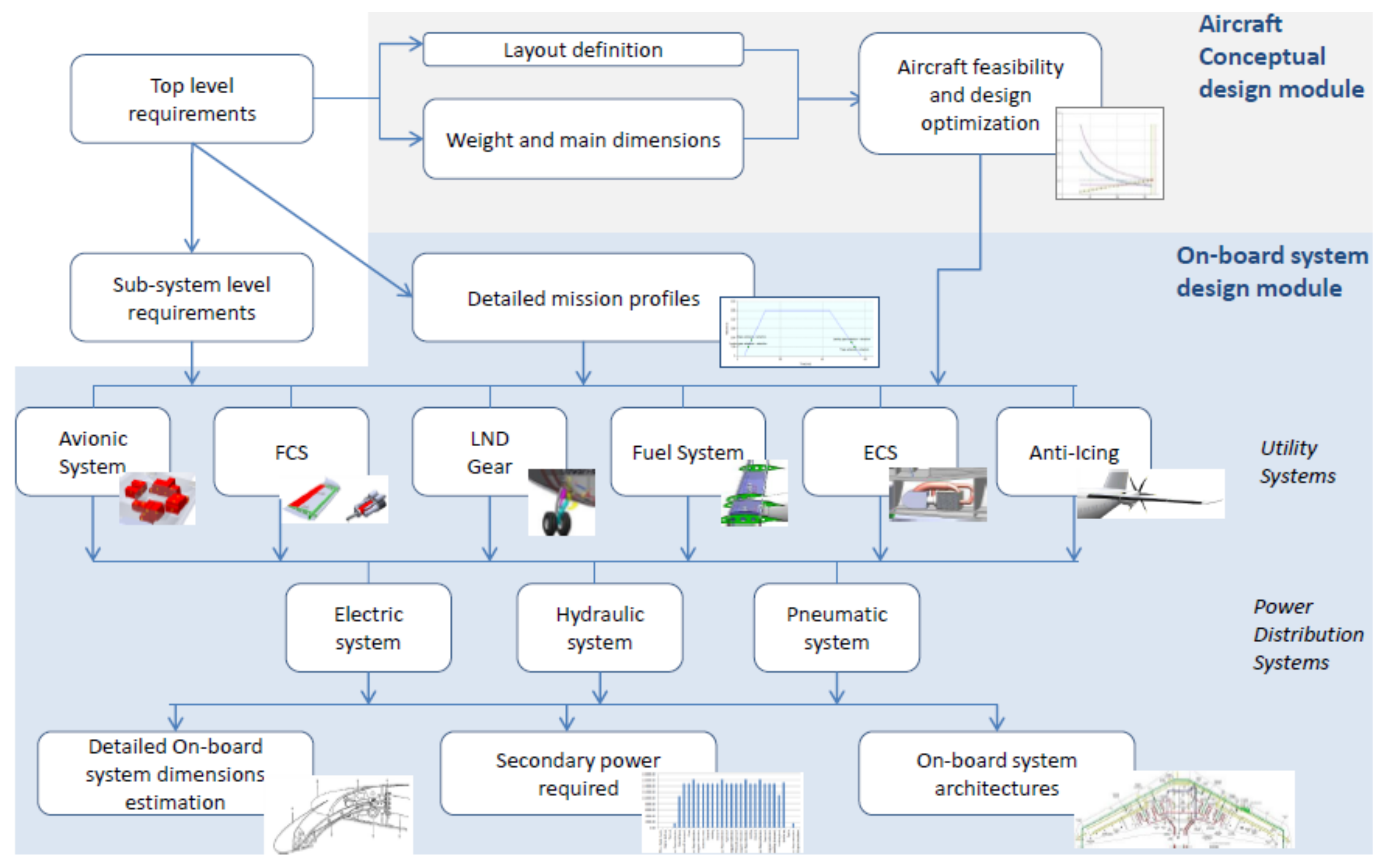
3. Implementation of the Design Workflows
3.1. Disciplinary Competences
3.1.1. OpenAD
3.1.2. ASTRID
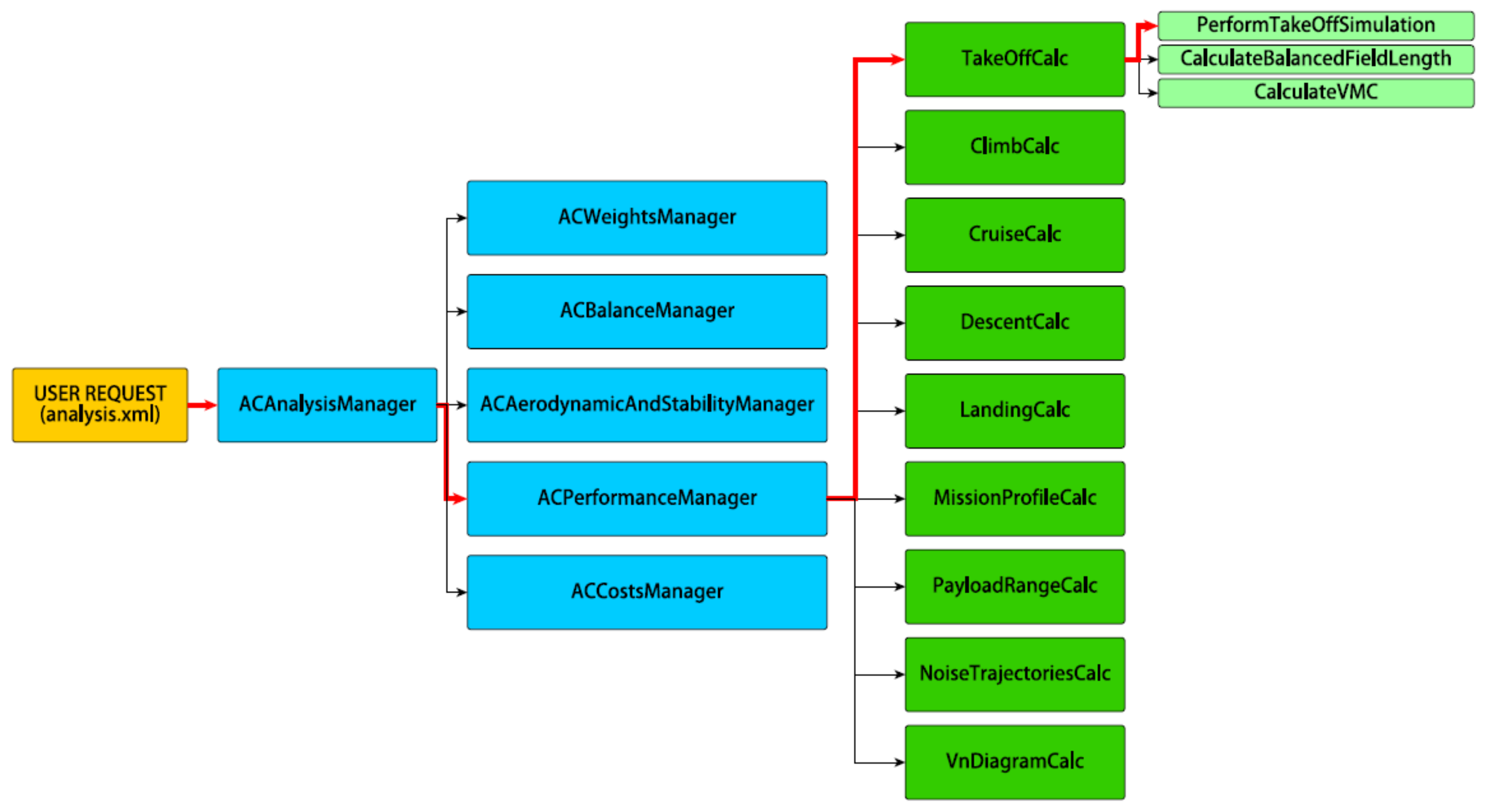
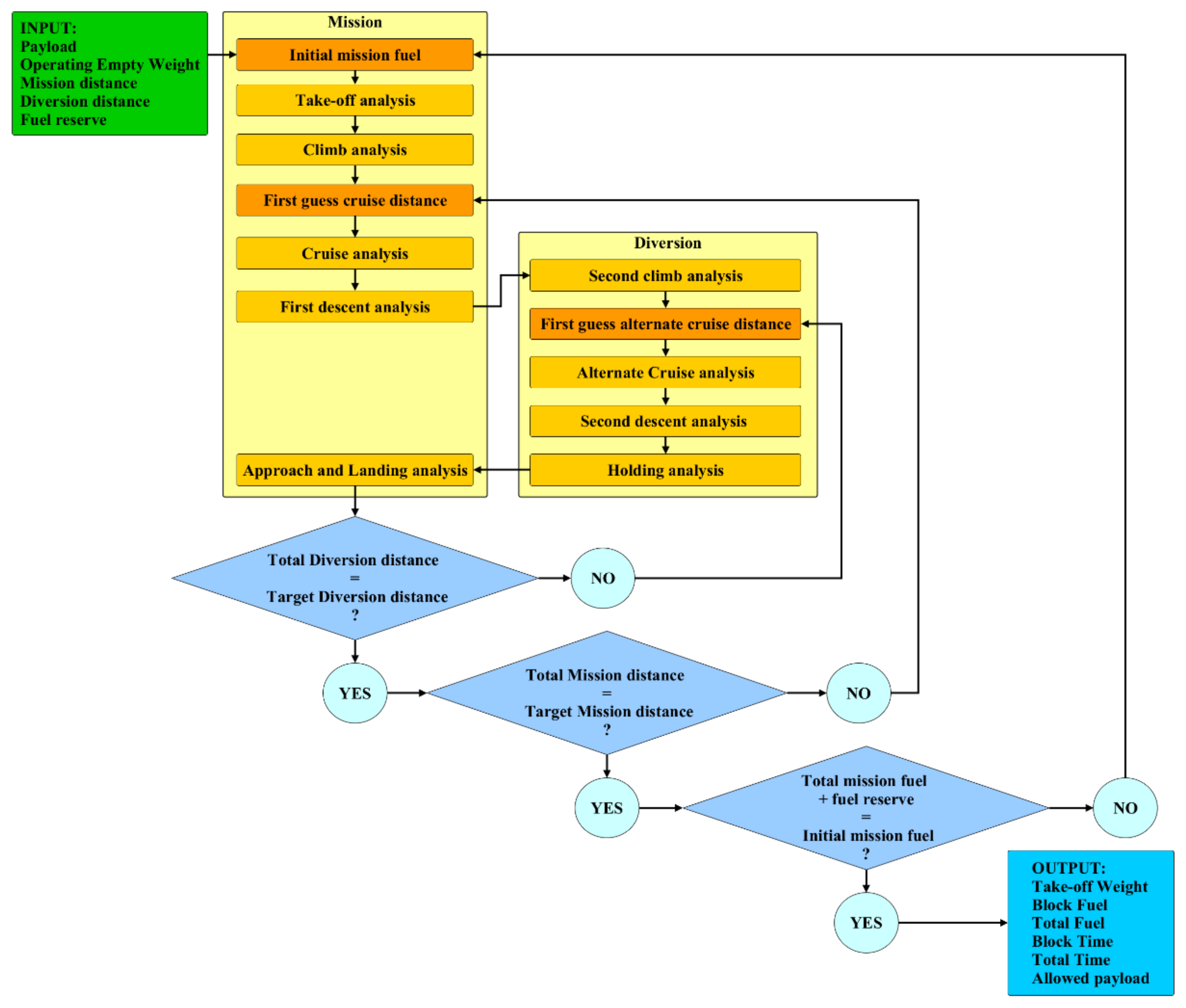
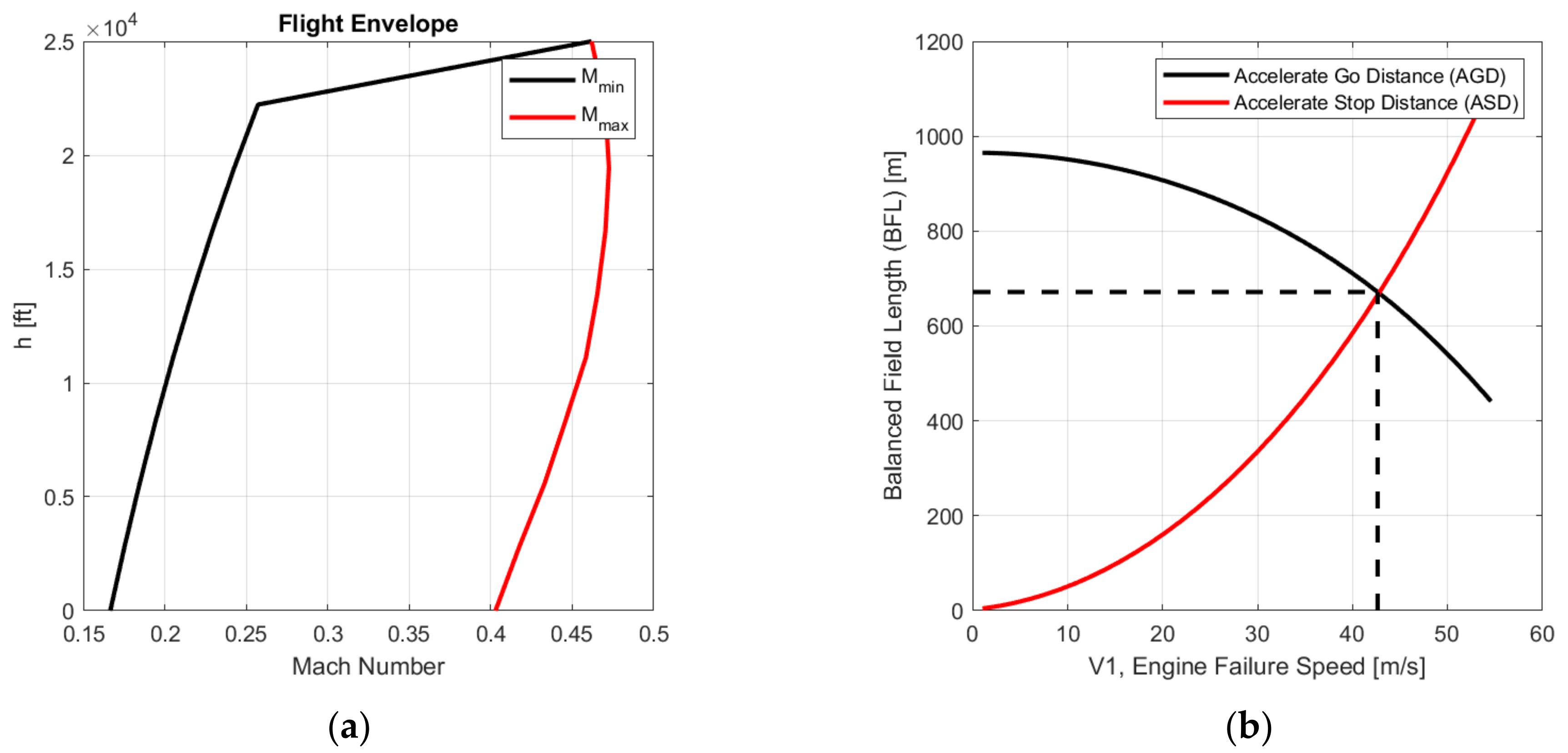
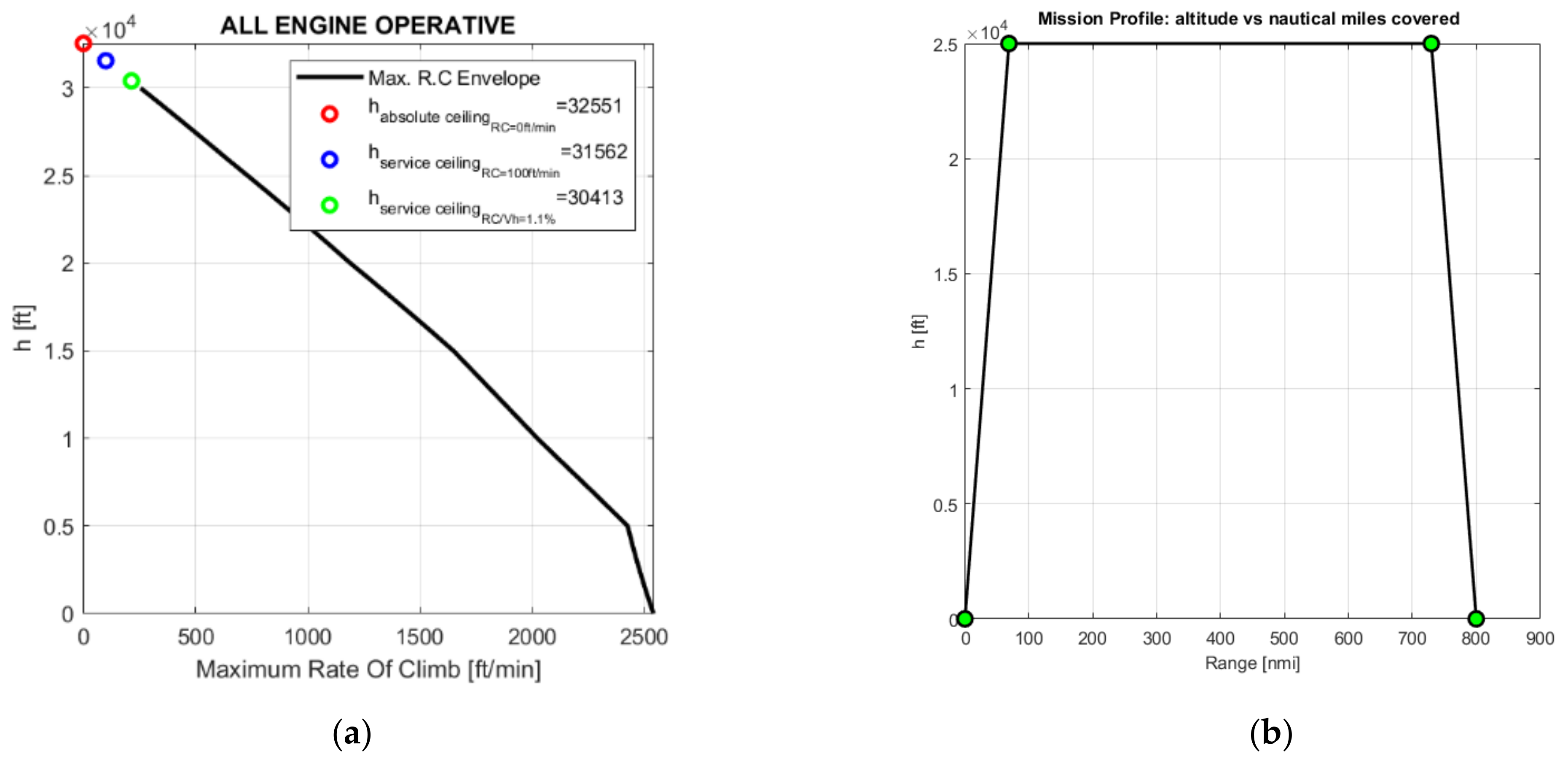
3.1.3. Performance
3.1.4. Engine
3.1.5. SFC Sensitivity
3.1.6. Aircraft Synthesis
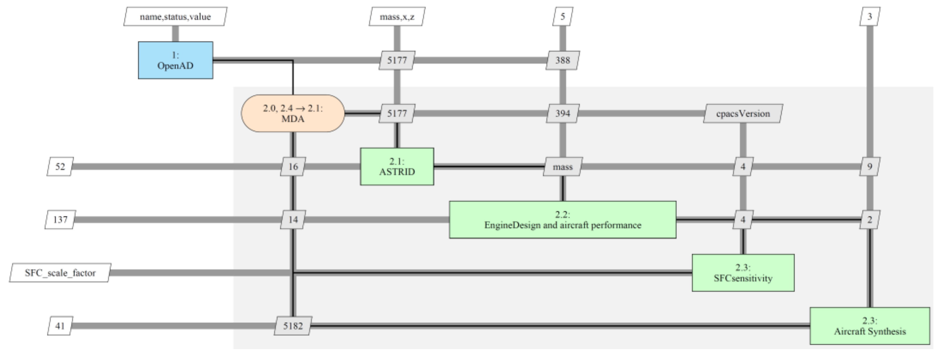
3.2. Analysis Workflow Definition
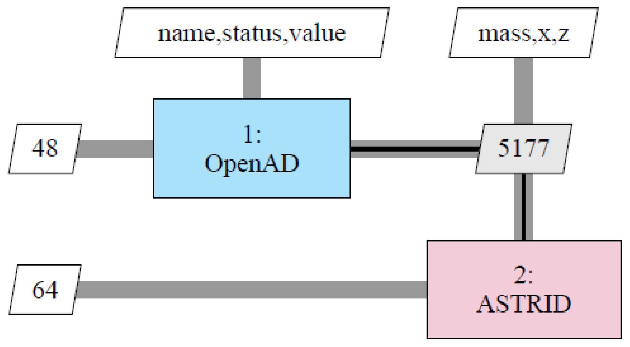
3.2.1. Workflow 1
3.2.2. Workflow 2
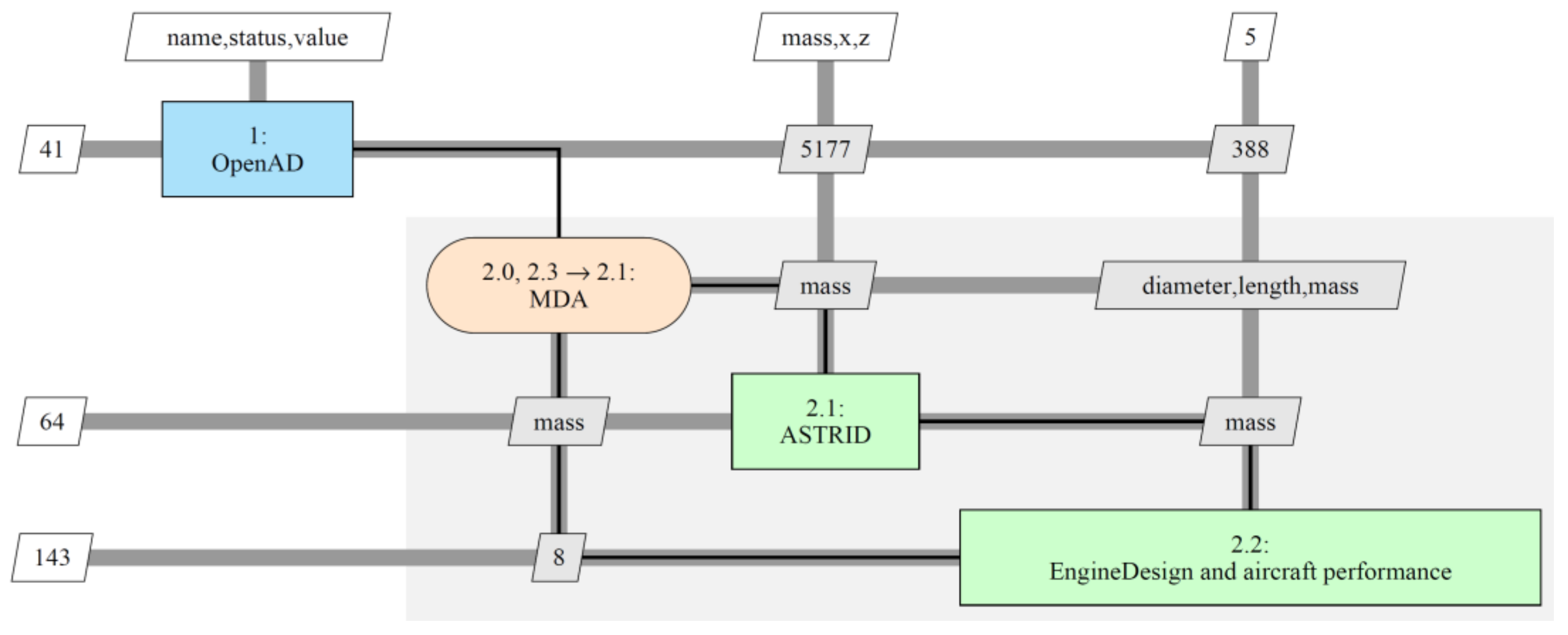
3.2.3. Workflow 3
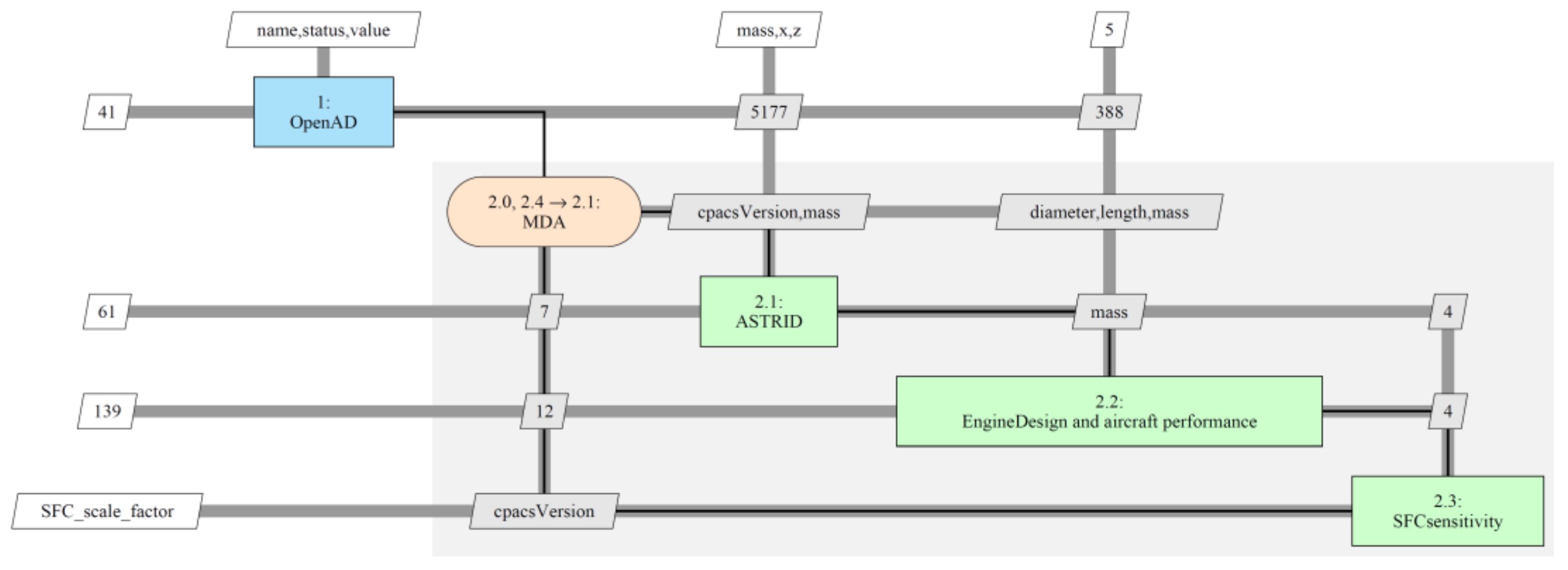
3.2.4. Workflow 4
4. Results and Discussions
4.1. Reference Aircraft
4.2. Workflow Comparisons
- The mass of the systems that do not participate in the electrification (e.g., avionics, furnishing, fire protection, oxygen, and lights) remain constant.
- The electrification of the actuation systems of the flaps and the landing gear slightly increases the mass of these systems due to the greater mass of the EHAs compared to the hydraulic actuators.
- An increase in the mass of the ECS and IPS can be noticed for the electrified architecture. This is mainly due to the use of additional components (i.e., electric motor compressors).
- The electrification only partially increases the EPGDS mass since the use of high voltage components partially dampens the increase in mass due to the use of more powerful components.
- The main advantage of the electrified architectures is given by the removal of the HPGDS and/or the PPGDS that always produces a reduction in the total systems mass.
- Finally, the OBS electrification always produces a beneficial effect in terms of mass reduction. MEA1 is the lightest architecture followed by the AEA and MEA2.

| Workflow n.1 | Workflow n.2 | Workflow n.3 | Workflow n.4 | |||||||||||||
|---|---|---|---|---|---|---|---|---|---|---|---|---|---|---|---|---|
| Masses (kg) | Conv | MEA1 | MEA2 | AEA | Conv | MEA1 | MEA2 | AEA | Conv | MEA1 | MEA2 | AEA | Conv | MEA1 | MEA2 | AEA |
| MTOM | 8630 | 8470 | 8564 | 8495 | 8633 | 8456 | 8563 | 8484 | 8619 | 8438 | 8530 | 8452 | 8620 | 8394 | 8511 | 8413 |
| ZFW | 7647 | 7486 | 7580 | 7511 | 7633 | 7464 | 7565 | 7491 | 7563 | 7391 | 7490 | 7416 | 7660 | 7454 | 7570 | 7482 |
| OEM | 5595 | 5434 | 5528 | 5459 | 5581 | 5413 | 5513 | 5439 | 5587 | 5415 | 5514 | 5440 | 5608 | 5402 | 5518 | 5430 |
| Airframe | n.a. | n.a. | n.a. | n.a. | n.a. | n.a. | n.a. | n.a. | n.a. | n.a. | n.a. | n.a. | 2356 | 2326 | 2342 | 2328 |
| M_FUEL | n.a. | n.a. | n.a. | n.a. | 1058 | 1049 | 1055 | 1050 | 1056 | 1046 | 1040 | 1036 | 1063 | 1042 | 1043 | 1033 |
| Operator items | 468 | 468 | 468 | 468 | 468 | 468 | 468 | 468 | 468 | 468 | 468 | 468 | 468 | 468 | 468 | 468 |
| Tot sys + Operator items | 2108 | 1948 | 2041 | 1973 | 2100 | 1930 | 2029 | 1956 | 2100 | 1930 | 2029 | 1956 | 2101 | 1927 | 2028 | 1953 |
| Avionics | 135 | 135 | 135 | 135 | 135 | 135 | 135 | 135 | 135 | 135 | 135 | 135 | 135 | 135 | 135 | 135 |
| FCS | 141 | 144 | 141 | 144 | 142 | 144 | 141 | 144 | 142 | 144 | 141 | 144 | 142 | 143 | 141 | 143 |
| IPS | 68 | 68 | 72 | 72 | 68 | 68 | 72 | 72 | 68 | 68 | 72 | 72 | 69 | 68 | 72 | 72 |
| ECS | 107 | 107 | 129 | 129 | 107 | 107 | 129 | 129 | 107 | 107 | 129 | 129 | 107 | 107 | 129 | 129 |
| Fuel systems | 55 | 55 | 55 | 55 | 40 | 40 | 39 | 39 | 40 | 40 | 39 | 39 | 40 | 40 | 40 | 39 |
| LNDG | 332 | 354 | 332 | 354 | 337 | 353 | 334 | 353 | 337 | 353 | 334 | 353 | 337 | 351 | 333 | 352 |
| Furnishing | 820 | 820 | 820 | 820 | 821 | 819 | 820 | 820 | 821 | 819 | 820 | 820 | 821 | 819 | 820 | 819 |
| Fire protection | 10 | 10 | 10 | 10 | 10 | 10 | 10 | 10 | 10 | 10 | 10 | 10 | 10 | 10 | 10 | 10 |
| Lights | 68 | 68 | 68 | 68 | 68 | 68 | 68 | 68 | 68 | 68 | 68 | 68 | 68 | 68 | 68 | 68 |
| Oxygen | 24 | 24 | 24 | 24 | 24 | 24 | 24 | 24 | 24 | 24 | 24 | 24 | 24 | 24 | 24 | 24 |
| Water Waste | 0 | 0 | 0 | 0 | 0 | 0 | 0 | 0 | 0 | 0 | 0 | 0 | 0 | 0 | 0 | 0 |
| APU | 0 | 0 | 0 | 0 | 0 | 0 | 0 | 0 | 0 | 0 | 0 | 0 | 0 | 0 | 0 | 0 |
| PPGDS | 56 | 56 | 0 | 0 | 56 | 56 | 0 | 0 | 56 | 56 | 0 | 0 | 56 | 56 | 0 | 0 |
| HPGDS | 99 | 0 | 94 | 0 | 99 | 0 | 94 | 0 | 99 | 0 | 94 | 0 | 99 | 0 | 94 | 0 |
| EPGDS | 194 | 107 | 163 | 163 | 194 | 107 | 163 | 163 | 194 | 107 | 163 | 163 | 194 | 107 | 163 | 163 |
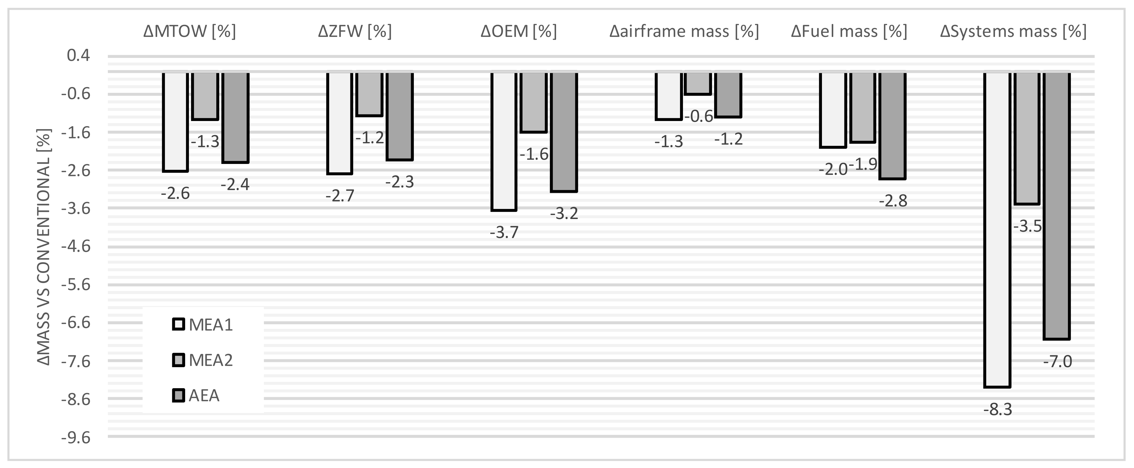
- Due to the complete removal of the HPGDS, the MEA1 and the AEA achieve a reduction in systems mass of about 8% and 7%, respectively;
- AEA architecture is able to reach the highest fuel mass saving (2.8%) due to the sum of two contributions: MTOM reduction due to OBS mass reduction and engine SFC enhancement due to the use of the bleedless technology. It is worth noting that MEA1 and MEA2 enable the same two contributions but separately. The reduction in fuel mass for MEA1 (2.0%) is only due to the lighter OBS, whereas for MEA2, the fuel reduction (1.9%) is mainly due to the use of bleedless technology. The effect of the two contributions on fuel saving is not linear and the overall effect cannot be represented by a simple sum of the individual contributions.
- Considering the mass distribution for this kind of aircraft, the mass saving obtained by electrifying the OBS is dampened for the other aircraft components (e.g., the airframe mass) and for the whole aircraft (e.g., OEM, MTOM, etc.). For example, the OBS mass saving of 8.3% achieved by MEA1 produced an MTOM reduction of 2.6%.
- Finally, considering the reduction in MTOM, the advantage obtained by adopting MEA1 and AEA architectures is similar. MEA2 is only able to achieve half of the mass saving of the other electrified OBS.

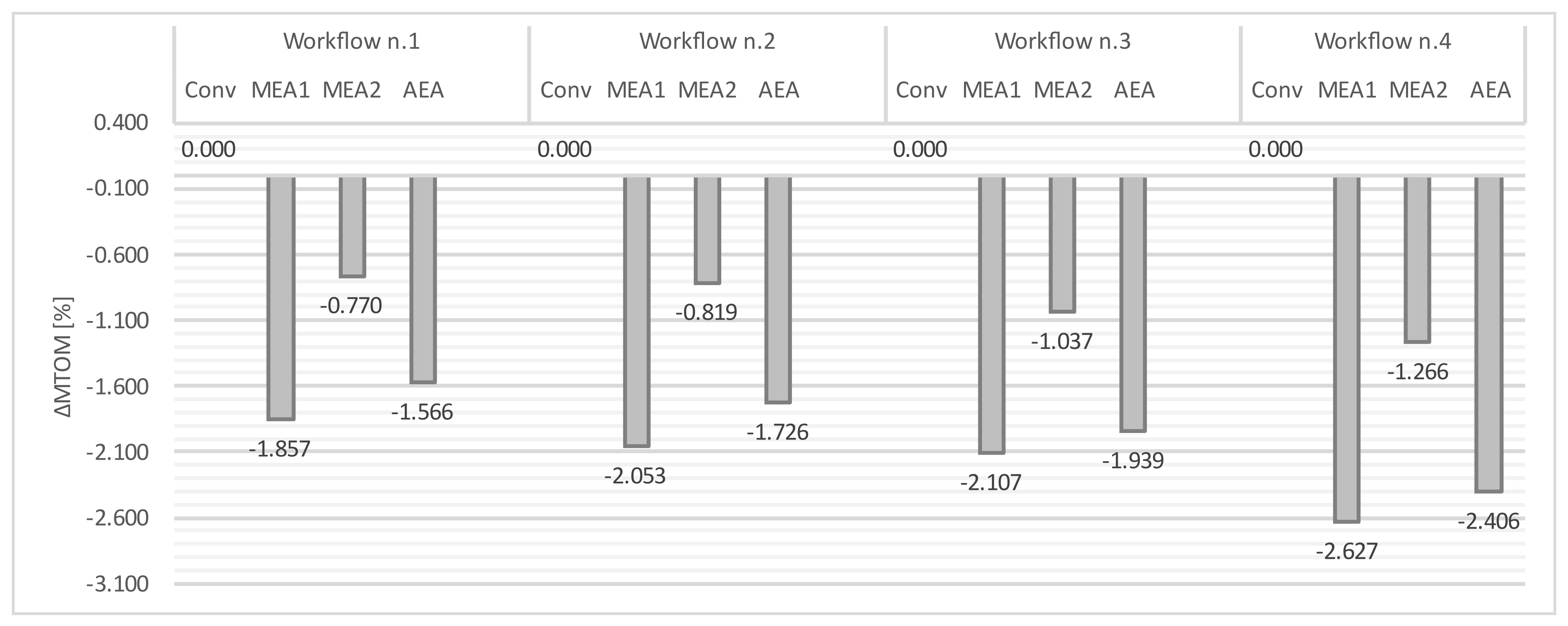
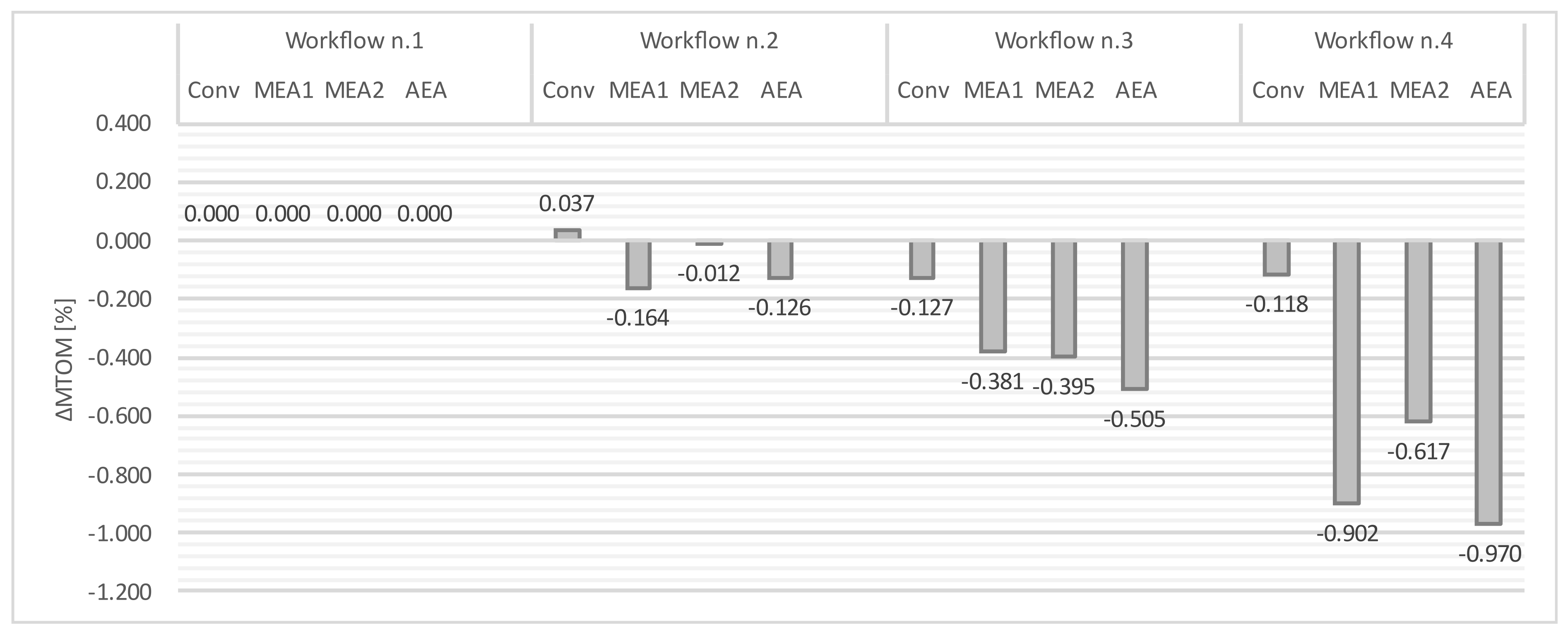
- Increasing the integration level, a variation of about 1% of MTOM can be observed when the results of workflow n.1 are compared with those of workflow n.4. A total of 1% of MTOM represents about 40% of the actual MTOM variation due to the different OBS architecture. This means that by using workflow n.1 an error of about 40% could be expected.
- For the conventional OBS architecture, the error is quite small when changing the integration level. It could be due to the assumptions considered in the other disciplinary tools that are already set for conventional systems. As a consequence, and looking at the variation for the other architectures, to correctly evaluate innovative systems, a workflow with a higher level of integration is necessary.
- Among the integrated disciplines, the SFC variation due to the OBS power offtakes represents an important improvement in the results, as shown in Figure 17 for workflow n.3. This is particularly true for the MEA2 architecture that in workflow n.2 produces the same effect as the conventional configuration.
- Finally, the aircraft redesign, discipline added in workflow n.4, is the greater contributor to the correct integration of the OBS design. The airframe and geometry redesign produce a notable effect on all the other disciplines involved (aircraft performance and engine design). This time, the enhancement added with workflow n.4 improves the results of the MEA1 and AEA architectures, that entail the greater mass reduction that can be correctly inherited by the other aircraft components by means of the aircraft synthesis.


5. Conclusions
Author Contributions
Funding
Acknowledgments
Conflicts of Interest
Abbreviations
| ACM | Air Cycle Machine |
| AEA | All Electric Aircraft |
| CAS | Calibrated Air Speed |
| ECS | Environmental Control System |
| EDP | Engine Driven Pump |
| EHA | Electro Hydrostatic Actuator |
| EPGDS | Electric Power Generation and Distribution System |
| FCS | Flight Control System |
| HPGDS | Hydraulic Power Generation and Distribution System |
| IPS | Ice Protection System |
| MDA | Multidisciplinary Design Analysis |
| MDAO | Multidisciplinary Design Analysis and Optimization |
| MEA | More Electric Aircraft |
| MTOM | Maximum Take Off Mass |
| OAD | Overall Aircraft Design |
| OBS | On-Board Systems |
| OEM | Operating Empty Mass |
| PPGDS | Pneumatic Power Generation and Distribution System |
| PPDU | Primary Power Distribution Unit |
| SFC | Specific Fuel Consumption |
| SPDU | Secondary Power Distribution Unit |
| TLARs | Top Level Aircraft Requirements |
| TOFL | Take Off Field Length |
| Level of electrification [−] | |
| Total electric power generated [W] | |
| Total non-propulsive power generated [W] |
References
- Cronin, M.J. All-Electric vs. Conventional Aircraft: The Production/Operational Aspects. J. Air. 1983, 20, 481–486. [Google Scholar] [CrossRef]
- Sinnet, M. 787 No-Bleed Systems: Saving Fuel and Enhancing Operational Efficiencies. Aero Q. 2007, 18, 6–11. [Google Scholar]
- Della Vecchia, P.; Stingo, L.; Nicolosi, F.; De Marco, A.; Cerino, G.; Ciampa, P.D.; Prakasha, P.S.; Fioriti, M.; Zhang, M.; Mirzoyan, A.; et al. Advanced turboprop multidisciplinary design and optimization within AGILE project. In Proceedings of the 2018 Aviation Technology, Integration, and Operations Conference, Atlanta, GA, USA, 25–29 June 2018; p. 3205. [Google Scholar]
- Jones, R.I. The more electric aircraft—assessing the benefits. J. Aero. Eng. 2002, 216, 259–269. [Google Scholar] [CrossRef]
- Fioriti, M.; Vercella, V.; Viola, N. Cost-Estimating Model for Aircraft Maintenance. AIAA J. Aircr. 2018, 55, 1564–1575. [Google Scholar] [CrossRef]
- Chiesa, S.; Fioriti, M. UAV logistic support definition. In Handbook of Unmanned Aerial Vehicles; Springer: Dordrecht, The Netherlands, 2015; pp. 2565–2600. [Google Scholar] [CrossRef]
- Raymer, D.P. Aircraft Design: A Conceptual Approach; AIAA Education Series: Washington, DC, USA, 1992. [Google Scholar]
- Roskam, J. Airplane Design, 2nd ed.; Roskam Aviation and Engineering DAR Corporation: Lawrence, KS, USA, 1989. [Google Scholar]
- Torenbeek, E. Synthesis of Subsonic Airplane Design, 1st ed.; Nijgh-Wolters-Noordhoff: Rotterdam, The Netherlands, 1976. [Google Scholar]
- Pires, R.M.M.; Lajux, V.; Fielding, J.P. Methodology for the Design and Evaluation of Wing Leading Edge and Trailing Edge Devices. In Proceedings of the International Congress of the Aeronautical Sciences, Hamburg, Germany, 3–8 September 2006. [Google Scholar]
- Sobieszczanski-Sobieski, J. Multidisciplinary Design Optimization: An Emerging New Engineering Discipline. In Advances in Structural Optimization; Springer: Dordrecht, The Netherlands, 1995; pp. 483–496. [Google Scholar]
- Werner-Westphal, C.; Heinze, W.; Horst, P. Multidisciplinary Integrated Preliminary Design Applied to Unconventional Aircraft Configuration. J. Air. 2008, 45, 581–590. [Google Scholar] [CrossRef]
- Allison, D.L.; Alyanak, E.J.; Shimmin, K. Aircraft system effects including propulsion and air cycle machine coupled interactions. In Proceedings of the 57th AIAA/ASCE/AHS/ASC Structures, Structural Dynamics, and Materials Conference, San Diego, CA, USA, 4–8 January 2016. [Google Scholar]
- Jeyaraj, A.K.; Tabesh, N.; Liscouet-Hanke, S. Connecting Model-based Systems Engineering and Multidisciplinary Design Analysis and Optimization for Aircraft System Architecting. In Proceedings of the 2021 Aviation ForumVirtual Event, Online, 2–6 August 2021. [Google Scholar]
- Chakraborty, I.; Mavris, D.N. Integrated Assessment of Aircraft and Novel Subsystem Architectures in Early Design. In Proceedings of the 54th AIAA Aerospace Sciences Meeting, San Diego, CA, USA, 4–8 January 2016. [Google Scholar]
- Ciampa, P.D.; Nagel, B.; La Rocca, G. A MBSE Approach to MDAO Systems for the Development of Complex Products. In Proceedings of the AIAA AVIATION 2020 FORUM, Virtual, Online, 15–19 June 2020. [Google Scholar]
- EASA. Certification Specifications for Normal, Utility, Aerobatic and Commuter Category Aeroplanes. CS-23 Initial Issue 2003, 3, 9. [Google Scholar]
- Fioriti, M.; Boggero, L.; Prakasha, P.; Mirzoyan, A.; Aigner, B.; Anisimov, K. Multidisciplinary aircraft integration within a collaborative and distributed design framework using the AGILE paradigm. Pro. Aer. Sci. 2020, 119, 100648. [Google Scholar] [CrossRef]
- Woehler, S.; Atanasov, G.; Silberhorn, D.; Fröhler, B.; Zill, T. Preliminary Aircraft Design within a Multidisciplinary and Multifidelity Design Environment. In Proceedings of the Aerospace Europe Conference, Bordeaux, France, 25–28 February 2020. [Google Scholar]
- Liersch, C.; Hepperle, M.A. A distributed toolbox for multidisciplinary preliminary aircraft design. CEAS Aer. J. 2011, 2, 57–68. [Google Scholar] [CrossRef]
- Zill, T.; Böhnke, D.; Nagel, B. Preliminary Aircraft Design in a Collaborative Multidisciplinary Design Environment. In Proceedings of the 11th AIAA Aviation Technology, Integration and Operations Conference, Virginia Beach, VA, USA, 20–22 September 2011. [Google Scholar]
- Torenbeek, E. Synthesis of Subsonic Airplane Design, 2nd ed.; Nijgh-Wolters-Noordhoff: Rotterdam, The Netherlands, 1984. [Google Scholar]
- Torenbeek, E. Advanced Aircraft Design, 1st ed.; Wiley Aerospace Series: Chichester, UK, 2013. [Google Scholar]
- Jenkinson, L.R.; Simpkin, P.; Rhodes, D. Civil Jet Aircraft Design; Hodder Headline Group: London, UK, 1999. [Google Scholar]
- Wells, D.P.; Horvath, B.L.; McCullers, L.A. The Flight Optimization System—Weights Estimation Method; NASA Langley Research Center: Hampton, VA, USA, 2017. [Google Scholar]
- Chiesa, S.; Fioriti, M.; Viola, N. Methodology for an integrated definition of a System and its Subsystems: The case-study of an Airplane and its Subsystems. In Systems Engineering-Practice and Theory; Cogan, B., Ed.; IntechOpen: London, UK, 2012; Available online: https://www.intechopen.com/chapters/32615 (accessed on 7 February 2022). [CrossRef] [Green Version]
- Nicolosi, F.; De Marco, A.; Attanasio, L.; Della Vecchia, P. Development of a Java-Based Framework for Aircraft Preliminary Design and Optimization. J. Aerosp. Inf. Syst 2016, 13, 234–242. [Google Scholar] [CrossRef] [Green Version]
- De Marco, A.; Trifari, V.; Nicolosi, F.; Ruocco, M. A simulation-based performance analysis tool for aircraft design workflows. Aerospace 2020, 7, 155. [Google Scholar] [CrossRef]
- Trifari, V.; Ruocco, M.; Cusati, V.; Nicolosi, F.; De Marco, A. Java Framework for Parametric Aircraft Design—Ground Performance. Aircr. Eng. Aerosp. Technol. 2017, 89, 599–608. [Google Scholar] [CrossRef] [Green Version]
- Trifari, V. Development of a Multi-Disciplinary Analysis and Optimization framework and applications for innovative efficient regional aircraft. Ph.D. Thesis, University of Naples Federico II, Naples, Italy, 2020. [Google Scholar]


| N. of passengers | 19 |
| Maximum Range | 1500 km |
| Speed | 0.45 M @ 7620 m |
| Operative Ceiling | 7620 m |
| TOFL | 800 m |
| MTOM | ≤8600 kg |
| Specifications | Value | Unit |
|---|---|---|
| N Pilots | 2 | - |
| N Pax | 19 | - |
| Mass per Pax | 93 | kg |
| Max Payload | 2052 | kg |
| Design Range | 1500 | km |
| Design Payload | 1976 | kg |
| Design Cruise Mach | 0.45 | - |
| sTOFL | 800 | m |
| Cruise Altitude | 7620 | m |
| Wing Loading | 265 | kg/m2 |
| Power/MTOM | 0.257 | kW/kg |
| MTOM | 8478 | kg |
| OEM | 5442 | kg |
| MZFW | 7495 | kg |
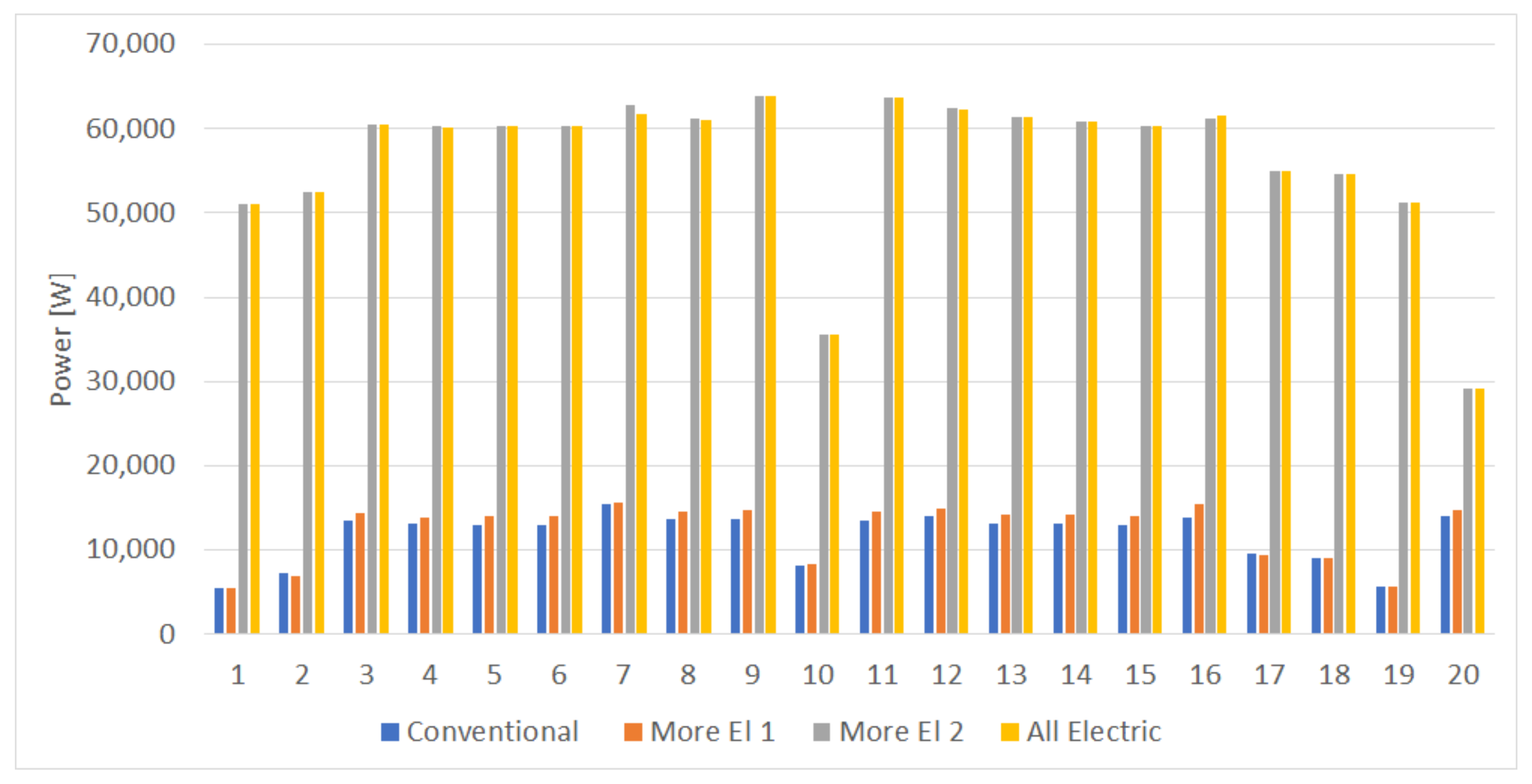
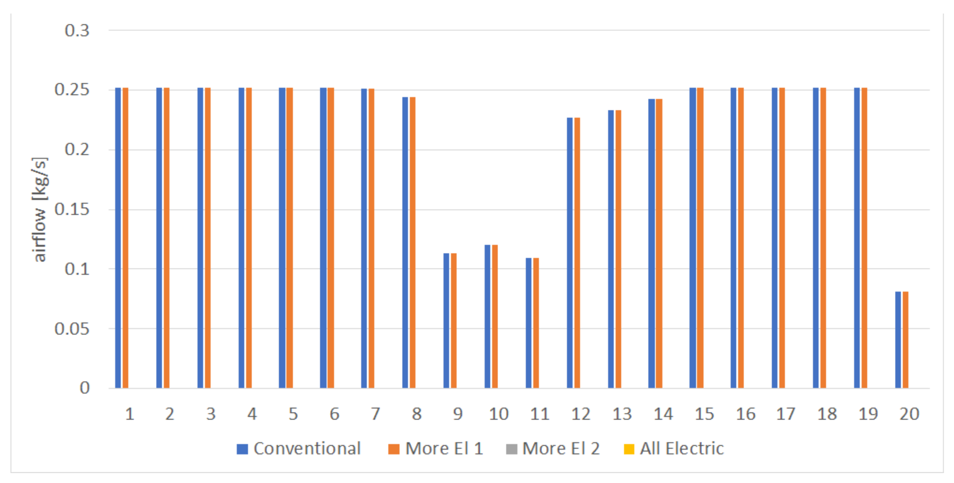
| Mechanical Power (W) | Pneumatic Airflow (kg/s) | ||||||||
|---|---|---|---|---|---|---|---|---|---|
| Mission Phase | Conv | MEA1 | MEA2 | AEA | Conv | MEA1 | MEA2 | AEA | |
| 1 | Pre—flight checks | 5410 | 5402 | 50,999 | 50,999 | 0.25 | 0.25 | 0 | 0 |
| 2 | Engine start-up | 7162 | 6886 | 52,482 | 52,482 | 0.25 | 0.25 | 0 | 0 |
| 3 | Taxi out | 13,415 | 14,336 | 60,564 | 60,513 | 0.25 | 0.25 | 0 | 0 |
| 4 | Taxi out—flaps down | 13,111 | 13,928 | 60,235 | 60,104 | 0.25 | 0.25 | 0 | 0 |
| 5 | Take off—run | 13,029 | 14,104 | 60,275 | 60,275 | 0.25 | 0.25 | 0 | 0 |
| 6 | Take off—manoeuvre | 13,029 | 14,104 | 60,263 | 60,263 | 0.25 | 0.25 | 0 | 0 |
| 7 | Take off—lnd gear up | 15,396 | 15,563 | 62,847 | 61,675 | 0.25 | 0.25 | 0 | 0 |
| 8 | Take off—flaps up | 13,657 | 14,534 | 61,123 | 61,044 | 0.24 | 0.24 | 0 | 0 |
| 9 | Climb | 13,686 | 14,702 | 63,913 | 63,913 | 0.11 | 0.11 | 0 | 0 |
| 10 | Cruise | 8149 | 8254 | 35,479 | 35,479 | 0.12 | 0.12 | 0 | 0 |
| 11 | Descent | 13,544 | 14,530 | 63,692 | 63,692 | 0.11 | 0.11 | 0 | 0 |
| 12 | Descent—flaps down | 14,039 | 14,822 | 62,410 | 62,331 | 0.23 | 0.23 | 0 | 0 |
| 13 | Approach—lnd gear down | 13,142 | 14,221 | 61,389 | 61,389 | 0.23 | 0.23 | 0 | 0 |
| 14 | Approach | 13,139 | 14,217 | 60,847 | 60,847 | 0.24 | 0.24 | 0 | 0 |
| 15 | Landing—manoeuvre | 13,029 | 14,104 | 60,265 | 60,265 | 0.25 | 0.25 | 0 | 0 |
| 16 | Landing—run | 13,861 | 15,378 | 61,207 | 61,561 | 0.25 | 0.25 | 0 | 0 |
| 17 | Taxi in—flaps up | 9539 | 9323 | 55,050 | 54,919 | 0.25 | 0.25 | 0 | 0 |
| 18 | Taxi in | 9020 | 9006 | 54,654 | 54,602 | 0.25 | 0.25 | 0 | 0 |
| 19 | Engine shutdown | 5631 | 5670 | 51,266 | 51,266 | 0.25 | 0.25 | 0 | 0 |
| 20 | Emergency | 14,001 | 14,783 | 29,157 | 29,077 | 0.08 | 0.08 | 0 | 0 |
Publisher’s Note: MDPI stays neutral with regard to jurisdictional claims in published maps and institutional affiliations. |
© 2022 by the authors. Licensee MDPI, Basel, Switzerland. This article is an open access article distributed under the terms and conditions of the Creative Commons Attribution (CC BY) license (https://creativecommons.org/licenses/by/4.0/).
Share and Cite
Fioriti, M.; Della Vecchia, P.; Donelli, G. Effect of Progressive Integration of On-Board Systems Design Discipline in an MDA Framework for Aircraft Design with Different Level of Systems Electrification. Aerospace 2022, 9, 161. https://doi.org/10.3390/aerospace9030161
Fioriti M, Della Vecchia P, Donelli G. Effect of Progressive Integration of On-Board Systems Design Discipline in an MDA Framework for Aircraft Design with Different Level of Systems Electrification. Aerospace. 2022; 9(3):161. https://doi.org/10.3390/aerospace9030161
Chicago/Turabian StyleFioriti, Marco, Pierluigi Della Vecchia, and Giuseppa Donelli. 2022. "Effect of Progressive Integration of On-Board Systems Design Discipline in an MDA Framework for Aircraft Design with Different Level of Systems Electrification" Aerospace 9, no. 3: 161. https://doi.org/10.3390/aerospace9030161